ECA 150 ipro B - Fan Maico - Free user manual and instructions
Find the device manual for free ECA 150 ipro B Maico in PDF.
| Product type | Extraction fan |
| Brand | Maico |
| Model | ECA 150 ipro B |
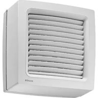
| Use | Air extraction for small rooms (bathrooms, toilets, storerooms, etc.) |
| Wall hole diameter | 150 mm (minimum), 170 mm recommended with WH 150 duct |
| Weight | 1.607 kg |
| Power supply | 230 V, 50 Hz |
| Extraction power | 2 levels: 200 m³/h (level 1) and 250 m³/h (level 2) in free blow |
| Motion detector | Range 5 m, horizontal angle 100°, vertical angle 82° |
| Timer operating time | Adjustable: 0, 8, 17 or 25 minutes |
| Control programs | 4 programs (comfort, need, economic, power) selectable via jumpers |
| Mounting type | Wall or ceiling |
| Electrical connection | Surface-mounted (AP) or flush-mounted (UP); cable 3 x 1.5 mm² |
| Protection rating | Fan: IP X5; switch/control: IP 00 |
| Fluid temperature | Max. +40 °C |
| Maintenance | Maintenance-free; regular cleaning with a dry cloth; protective cover washable with water |
| Safety | Motor thermal protection, automatic shutdown in case of overheating and restart after cooling |
| Spare parts | Electronic boards, covers, detectors (ref. SE ECA 150 ipro B E157.0145.0000) |
| Installation | Reserved for a qualified electrician in accordance with applicable standards |
Frequently Asked Questions - ECA 150 ipro B Maico
User questions about ECA 150 ipro B Maico
0 question about this device. Answer the ones you know or ask your own.
Ask a new question about this device
Download the instructions for your Fan in PDF format for free! Find your manual ECA 150 ipro B - Maico and take your electronic device back in hand. On this page are published all the documents necessary for the use of your device. ECA 150 ipro B by Maico.
USER MANUAL ECA 150 ipro B Maico
| 1 Electronic circuit boards [1.1] to [1.4] |
| 2 Housing with motor and impeller |
| 3 Cable grommet – flush-mounted connec-tion |
| 4 Cable grommet – surface-mounted con-necton |
| 5 Electronics cover [5.1] or [5.2] |
| 6 Internal grille or internal shutter |
| 6.1 Fixed internal grille |
| 6.2 Electric internal shutter (K-units) |
| 6.3 Thermo-bimetal (K-units) |
| 7 Cover [7.1] or [7.2] |
| 8 Designer cover |
| 9 Sensors |
| 9.1 Motion sensor (B, KB) |
| 9.2 Humidity sensor (H, KH, RCH, KRCH) |
| 10 LEDs for pos. [11] and [12] |
| 11 Setting button for start delay,teach-in button for RC and RCH units |
| 12 Setting button for overrun time/LED (RC units) |
| 13 Spring terminal |
| S1 Rating plate / ECA 150 ipro circuit dia-gram |
| S2.1/S2.2 Rating plate / ECA 150 ipro K circuit dia-gram |
Table of contents
1 Scope of delivery 22
2 Specialist installer qualifications 22
3 Intended use 22
4 Safety instructions 22
4.1 General safety instructions 22
4.2 Safety instructions regarding installation, operation, cleaning and maintenance 22
5 Product information 23
5.1 ECA 150 ipro, ECA 150 ipro K ......... 23
5.2 ECA 150 ipro VZC, ECA 150 ipro 24 KVZC
5.3 ECA 150 ipro B, ECA 150 ipro KB... 24
5.4 ECA 150 ipro H, ECA 150 ipro KH .. 24
5.5 ECA 150 ipro RC, ECA 150 ipro 25 KRC.
5.6 ECA 150 ipro RCH, ECA 150 ipro 25 KRCH
5.7 Unit versions 25
5.8 MAICOsmart system description.... 26
6 Technical data. 27
6.1 Ambient conditions 27
6.2 Technical data table 27
7 Preparation for installation 28
7.1 Wall 28
7.2 Ceiling 28
7.3 Duct 28
8 Installation and commissioning 28
8.1 Fan 28
8.2 Housing installation 29
8.3 Electrical connection 29
8.4 Operating programs 30
8.5 Final installation 30
8.6 Commissioning 31
8.7 Start delay and overrun time 32
9 Radio components 32
9.1 Procedure 32
9.2 Tips for teaching-in radio components 32
9.3 Program levels.. 33
9.4 Switching a receiver to teach-in 33 mode
9.5 Teaching-in transmitters 33
9.6 Deleting transmitters 34
9.7 Setting up the fan as a signal amplifier (Repeater) 34
10 Operation 35
11 Maintenance. 35
12 Cleaning 35
13 Fault rectification 36
14 Spare parts. 36
15 Dismantling 37
16 Environmentally responsible disposal. 37
Acknowledgements. 37
Wiring diagrams 59
Preface
Please read the instructions carefully before installing and using for the first time. Follow the instructions. Pass these instructions on to the owner for safekeeping.
1 Scope of delivery
Fan
Foam strip
- Installation and operating instructions
2 Specialist installer qualifications
Installation may only be carried out by trained specialists who have the necessary knowledge and experience in ventilation engineering. The unit must be connected in accordance with the national technical approval.
Only a qualified electrician is permitted to work on the electrics. You are deemed a qualified electrician if you are familiar with the relevant standards and guidelines, can competently and safely connect units to an electrical power supply in line with the Wiring diagrams and are able to recognise and avoid risks and dangers associated with electricity on the basis of your technical training and experience.
3 Intended use
The unit is used for extracting air from bathrooms, toilets, storage rooms, showrooms, cellars, offices, communal showers in clubhouses, fitness centres, changing rooms and similar rooms.
Operation is only permitted with:
- a fixed installation within buildings
- installation on walls or ceilings
- an air supply via shaft or duct
- electrical flush-mounted connections
Master-slave operation of RC units is only possible with similar kinds of ECA 150 ipro RC/RCH/KRC/KRCH units.
This unit is only intended for domestic use and similar purposes.
4 Safety instructions
4.1 General safety instructions
The unit must not be used in the following situations under any circumstances:
DANGER Risk of combustion/fire from flammable materials, liquids or gases in the vicinity of the unit.
Do not place any flammable materials, liquids or gases near the unit, which may ignite in the event of heat or sparks and catch fire.
DANGER Explosive gases and dust may ignite and cause serious explosions or fire. Never use fan unit in an explosive atmosphere (risk of explosion).
WARNING Risk from operating in single air extraction systems in accordance with DIN 18017-3.
Fan does not satisfy the DIN 18017-3 standard. Do not use fan in systems in accordance with DIN 18017-3.
WARNING Risk to health from chemicals or aggressive gases/vapours.
Chemicals or aggressive gases/vapours may harm health, especially if they are distributed throughout the rooms by the unit.
Never use unit to distribute chemicals or aggressive gases/vapours.
NOTICE Damage to unit due to grease and oil vapours from range hoods.
Grease and oil vapours from range hoods may contaminate the unit and air ducts and reduce efficiency.
Never use unit to convey these substances.
4.2 Safety instructions regarding installation, operation, cleaning and maintenance
DANGER Risks for children and people with reduced physical, sensory or mental capabilities or a lack of knowledge.
Unit may only be installed, commissioned, cleaned and maintained by persons who can safely recognise and avoid the risks associated with this work.
WARNING Risk of injury due to suction from unit and rotating impeller.
Hair, clothing, jewellery etc. may be pulled into the unit if you get too close to it.
During operation, always keep far enough away to prevent this from happening.
WARNING Risk of injury if foreign objects are inserted into the unit.
Do not insert any objects in the unit.
NOTICE A fan that is not installed correctly may result in non-intended operation or impermissible operation.
Operation is only permitted with a correct installation position (see TOP on unit), with mounted design cover and outer protective grille.
The fan may be operated only if the protection against accidental contact with the impeller is guaranteed to be in accordance with DIN EN ISO 13857.
WARNING Risk of injury and health risk in the event of changes or modifications or if components which are not permitted are used.
The unit may only be operated with original components. Changes and modifications to the units are not permitted and release the manufacturer from any guarantee obligations and liability, e. g. if the housing is drilled at a point which is not permitted.
WARNING Risk of injury when working at heights.
Use appropriate climbing aids (ladders).
Stability should be ensured, if necessary have the ladders steadied by a 2nd person.
Ensure that you are standing securely and cannot lose your balance and that there is no one under the unit.
DANGER Risk of death from carbon monoxide when operating with air-ventilated fireplaces.
The maximum permitted pressure difference per residential unit is 4Pa . The consent of a professional chimney sweep is needed in all cases.
Ensure sufficient supply air intake during operation with an air-ventilated fireplace.
DANGER Danger of electric shock when operating a fan which is damaged or not fully mounted.
Before taking off the electronics cover, shut down all supply circuits (switch off mains fuse), secure against being accidentally switched back on and position a visible warning sign.
Only operate the fan when it is completely installed.
Do not commission a damaged unit.
DANGER Danger if the relevant regulations for electrical installations are not observed.
Before installing the electrics, shut down all supply circuits, deactivate the mains fuse and secure it so it cannot be switched back on. Attach a warning sign in a clearly visible place.
Be sure to observe the relevant regulations for electrical installation; e.g. DIN EN 50110-1. In Germany, particularly observe VDE 0100, with the corresponding sections.
A mains isolation device with contact openings of at least 3mm at each pole is mandatory.
Only connect unit to permanently wired electrical installation and with NYM-O or NYM-J cables, depending on the unit type, 3 × 1.5 ~mm^2 or 5 × 1.5 ~mm^2 .
The unit may only be operated using the voltage and frequency shown on the rating plate.
Unit may be energized even when at a standstill and may be started up automatically by sensors, such as those for time delay or humidity etc.
The degree of protection stated on the rating plate is only guaranteed if installation is undertaken correctly and if the connecting cable is correctly guided through the cable grommet. The grommet must tightly seal the cable sheathing.
With protection class I, connect the PE conductor and check the connection.
CAUTION Exercise caution when hand-ling packaging materials.
Observe applicable safety and accident prevention regulations.
Store packaging material out of the reach of children (risk of suffocation due to swallowing).
5 Product information
5.1 ECA 150 ipro, ECA 150 ipro K
- Small room fans for extracting air from rooms.
- Standard model.
ECA 150 ipro with fixed internal grille. - ECA 150 ipro K with electrically operated internal shutter.
- Two power levels as standard.
- On/off with light switch or separate switch.
- Can be operated at two levels with a standard double reversing switch.
Further product features Unit versions [25].
5.2 ECA 150 ipro VZC, ECA 150 ipro KVZC
- Small room fans for extracting air from rooms.
- Model with adjustable start delay and overrun time.
- ECA 150 ipro VZC with fixed internal grille.
- ECA 150 ipro KVZC with electrically operated internal shutter.
- Two power levels as standard. Operation in either level 1 or level 2.
- On/off with light switch or separate switch.
Further product features Unit versions [25].
5.3 ECA 150 ipro B, ECA 150 ipro KB
- Small room fans for extracting air from rooms.
- Model with motion detector and overrun time. No start delay.
- ECA 150 ipro B with fixed internal grille.
- ECA 150 ipro KB with electrically operated internal shutter.
- Barrier-free product as the fan switches itself on and off via the motion sensor.
- Motion sensor range 5m , horizontal monitoring range 100^ , vertical monitoring range 82^ .
- Two power levels as standard. Operation in either level 1 or level 2.
Operation possible without switch. Can optionally also be switched via separate switch.
Further product features Unit versions [25].
5.4 ECA 150 ipro H, ECA 150 ipro KH
- Small room fans for extracting air from rooms.
- Model with humidity control (fully automatic), start delay and overrun time.
ECA 150 ipro H with fixed internal grille.
ECA 150 ipro KH with electrically operated internal shutter. - Barrier-free product as the fan switches itself on and off via the humidity sensor.
- Switch-on humidity does not have to be set. Fan monitors the room humidity.
- 2 performance levels as a standard feature. Fan extracts air automatically in level 1 or level 2, depending on the room humidity.
Operation possible without switch. Can optionally also be switched via separate switch.
Further product features Unit versions [25].
Automatic humidity function
Once the fan is installed, it adjusts to the room humidity prevailing at that time (relative humidity). This humidity value is saved as the first reference value. The reference value does not have to be specified manually.
If the relative humidity falls below the reference value during operation, the newly established reference value is saved. The lowest possible reference value is 48% relative humidity.
When the room humidity increases
- If the room humidity increases by 7% , the fan switches on automatically at power level 1 (200 m^3/h ).
- If the humidity increases even further, the unit switches to power level 2 (250 m³/h).
- If there are no further increases, the fan continues to run at power level 1 (200 m³/h) until the humidity again falls below the saved reference value.
When falling below the reference value
- H and KH: Overrun operation starts with the set overrun time. The current reference value is then saved.
- RCH and KRCH: No overrun operation.
Value does not fall below reference value for 1 hour
- H and KH: Overrun operation starts. Fan then switches off.
- RCH and KRCH: Fan switches off.
Operation using light and/or radio switch
- H and KH units can also be operated using the light switch. With "Light on", the set operating programme starts with the start delay Operating programs [30] The operating program takes priority over the automatic humidity function. After switching off, the unit continues to run until the remaining overrun time has passed. The automatic humidity function is then assigned maximum priority again and controls the unit as described above.
- Optionally, RCH/KRCH units can be operated in 2 levels using a radio switch. Switching through the DS RC or window contact is possible during humidity operating mode.
5.5 ECA 150 ipro RC, ECA 150 ipro KRC
- Small room fans for extracting air from rooms.
- Radio-controlled fan for the MAICOsmart exhaust air system.
- Model with radio receiver 868 MHz (EnOcean).
ECA 150 ipro RC with fixed internal grille. - ECA 150 ipro KRC with electrically operated internal shutter.
- On/off via optional DS RC radio switch or separate RLS RC room air control.
- Two-level operation with optional radio switch or separate room air control.
- Master-slave operation of the RC fans only possible in ECA 150 ipro RC, RCH, KRC and KRCH single-type systems (RLS RC room air control required). Combinations with ECA 100 ipro RC/RCH and ECA 100 RC not permissible.
Further product features Unit versions [25].
5.6 ECA 150 ipro RCH, ECA 150 ipro KRCH
- Small room fans for extracting air from rooms.
- Radio-controlled fan for the MAICOsmart exhaust air system.
- Model with 868 MHz (EnOcean) radio receiver and humidity control.
ECA 150 ipro RC with fixed internal grille.
ECA 150 ipro KRC with electrically operated internal shutter. - Barrier-free product as the fan switches itself on and off via the humidity sensor.
- Switch-on humidity does not have to be set. Fan monitors humidity curve. Automatic air extraction depending on room humidity, at level 1 or 2.
- Two-level operation with separate DS RC radio switch or separate RLS RC room air control, also during humidity operating mode.
- Master-slave operation of the RC fans only possible in ECA 150 ipro RC, RCH, KRC and KRCH single-type systems (RLS RC room air control required). Combinations with ECA 100 ipro RC/RCH and ECA 100 RC not permissible.
Further product features Unit versions [25].
5.7 Unit versions
| Unit versions of ECA 150 ipro ... | Start delays [sec.] | Over-run time [min.] | Mains cable [mm²] | 4 op-erat-ing pro-grams | speed con-trol-lable |
| Stand-ard | 5 x 1.5 | ● | |||
| VZC 0/5 | 0/90/120 | 0/8/17/25 | 5 x 1.5 | ● | |
| H 0/50/90 | 0/120* | 8/17/25** | 3 x 1.5*** | ■ | |
| B 0/8/17/ | 25 | 3 x 1.5*** | ● | ||
| RC 3 x 1.5 | |||||
| RCH 3 x 1.5 | |||||
| K 5 x 1.5 | ● | ||||
| KVZC 0/50/90/120 | 0/8/17/25 | 0/8/17/25 | 5 x 1.5 | ● | |
| KH 0/50/90/120* | 8/17/25** | 3 x 1.5*** | ■ | ■ | |
| KB 0/8/17/ | 25 | 3 x 1.5*** | ● | ||
| KRC 3 x 1.5 | |||||
| KRCH 3 x 1.5 |
Bold Indicates delivery status
- Standard equipment
With optional light switch - Start delay available when using an optional switch (e.g. light switch).
Overrun time of 0 min available when using an optional switch (e.g. light switch).
* When using additional switch 5 × 1.5 mm^2 .
5.8 MAICOsmart system description
MAICOsmart network with radio electronics
-
Receivers are ECA 150 ipro fans of the RC, RCH, KRC and KRCH unit models.
Transmitters are system components such as -
RLS RC room air controls
- DS RC radio switches
-
radio window contacts
ECA 150 ipro RC, RCH, KRC and KRCH -
All the ECA 150 ipro RC models can be combined with each other in the network.
-
ECA 150 ipro RCH and KRCH fans also have humidity control (fully automatic humidity control).
-
The MAICOsmart system can be operated with a radio switch and/or the RLS RC room air control:
-
The two power levels can be selected or the system can be switched off with a radio switch.
-
With the RLS RC room air control, the three system levels can be switched on manually ( table in chapter Operation [35]).
-
This function is deactivated ex works in order to guarantee continuous ventilation. If need be, this function can also be activated ( RLS RC room air control installation instructions).
The fan can also be switched on/off with radio window contacts (window open/closed). - During commissioning, the transmitters must be taught-in on the receivers (must be paired with each other).
Further radio components
DS RC radio switch (EnOcean switch)
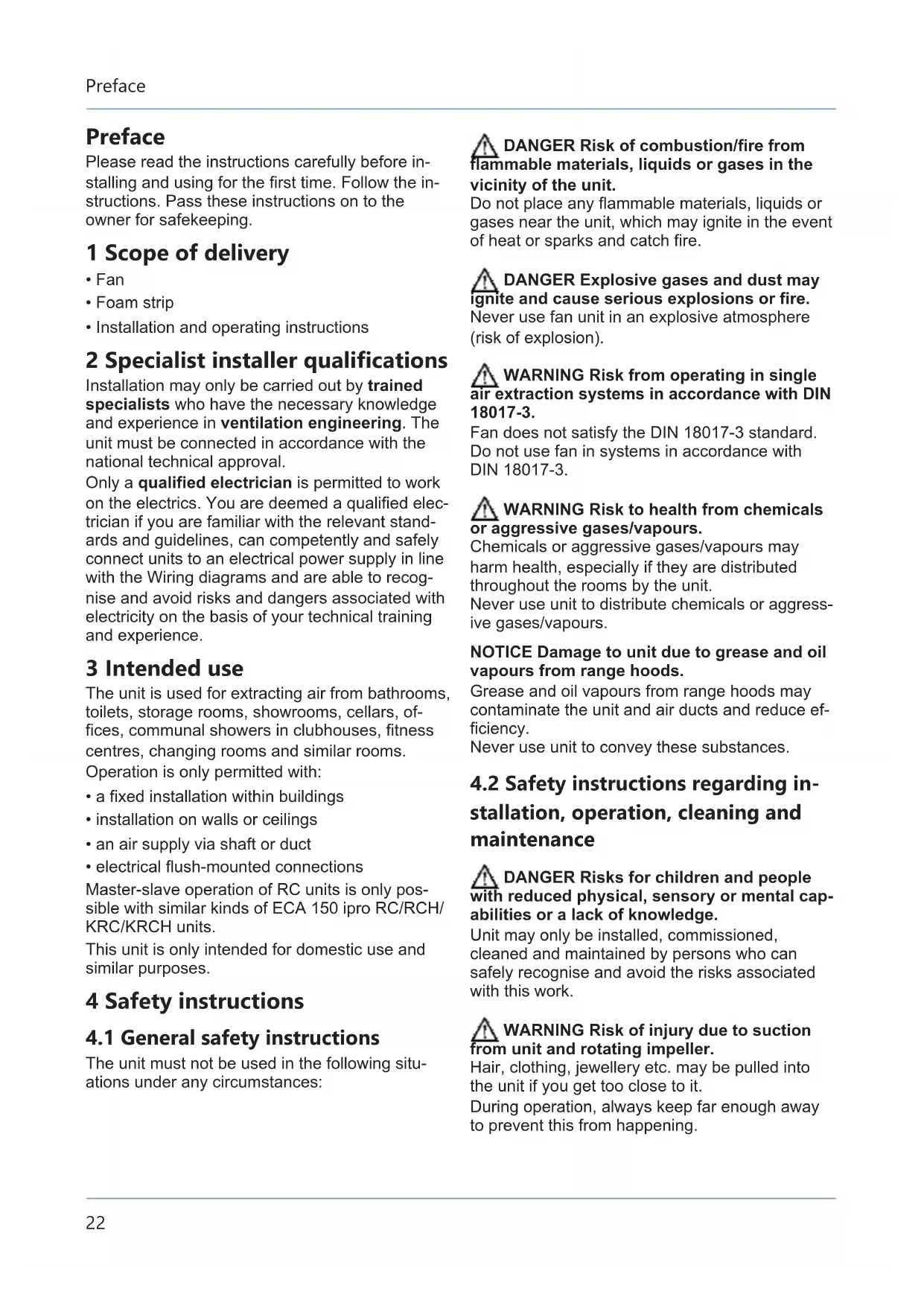
A: Fan with a radio switch in individual operation.
- Radio switch, (double rocker switch) for setting different fan power levels.
- Press the rocker switch to switch up or down one power level.
The left and right rocker switch have to be taught-in separately: Left rocker switch for on/off, right rocker switch to switch the ventilation level up and down.
Always teach in the radio switch for the fan that is located in the same room as the switch.
B: Fan with several radio switches in individual operation.
Function as described above. Up to 5 radio switches can be taught in per fan.
Radio switches in master/slave network
The ventilation system is operated according to the settings made on the RLS RC. However, every switching action made by radio switch has priority over the RLS RC setting.
-
If a radio switch is operated, the assigned fan switches to the manually selected power level.
After 30 minutes of the switch not being operated (timeout), the unit returns to the setting according to RLS RC. If the setting is changed on the RLS RC during the timeout, the assigned fan only reacts to this command once the timeout has elapsed. -
In the case of RCH/KRCH units, the automatic humidity function operates with priority. Switching through the DS RC or through a radio window contact is possible during humidity operating mode.
Radio window contact (EnOcean switch)
- Radio window contacts can be taught-in for each fan.
- The radio window contact sends the Window open or Window closed status to the assigned fan.
- The assigned fan switches off automatically if the window is opened.
- If you want the fan to continue to operate even when the window is open, it can be switched on with the assigned radio switch.
- The radio switch has priority over the radio window contact and/or the RLS RC.
- The fan switches off again after a timeout of approx. 30 minutes (if the window is still open) or back to the operation mode set on the RLS RC (if the window is closed).
- In the case of RCH/KRCH units, the automatic humidity function operates with priority. Switching through the DS RC or window contact is possible during humidity operation.
RLS RC room air control (EnOcean radio control)
For information about the RLS RC room air control, see separate installation instructions.
- The RLS RC room air control is a radio control for the manual operation of master and slave devices.
-
Two programs (P1/P2) with different power level combinations are available for operation.
The programme suitable for the application (P1 for small/P2 for large residential units, tables in chapter Operation [35]) is determined during commissioning.
The following appears in the RLS RC display: System level 0/Off without bar System level 1 with two bars System level 2 with 4 bars System level 3 with 6 bars
The time and temperature are also shown on the display. -
The holiday mode is equipped with interval operation. The on-off change takes place every 30 minutes for all fans (humidity protection). Radio commands from further radio network devices are ignored until holiday mode is switched off.
- Service menu for system settings.
6 Technical data
6.1 Ambient conditions
- Permissible maximum temperature of air medium +40^ .
- Sufficient supply air intake must be ensured during operation with air-ventilated fireplaces. The maximum permitted pressure difference per residential unit is 4Pa .
- Resistance to interference according to EN 55014-2 depending on pulse shape and energy component 1000 to 4000V . If operating with fluorescent tubes, extra interference suppression measures are needed (L or C components or RC modules, protection diodes, varistors) because these values may be exceeded.
- Storage: Store unit exclusively in a dry location (-20 to +50 °C).
6.2 Technical data table
| Rated voltage 230 V | |
| Power frequency 50 Hz | |
| Degree of protection ·Fan ·Switch, control | IP X5 IP 00 |
| Weight 1.607 kg |
Model B and KB (motion detector)
| Reach 5 m | |
| Coverage: • horizontal • vertical | 100° 82° |
Radio-controlled model RC, RCH, KRC, KRCH
| Radio components: Frequency range (in acc. with EN 300220-1) | 868.35 MHz |
| Operating distances in the building are dependent on the building materials used: ·RLS RC room air control / fan ·DS RC radio switch / | Up to: 30 m 30 m |
| fan • Fan / fan • Amplifier / fan | 30 m |
| 40 m |
For more technical data rating plate.
For characteristic curves www.maico-ventilatoren.com
7 Preparation for installation
7.1 Wall
Use mounting material suitable for base and of sufficient dimensions. Ensure sufficient supply air.
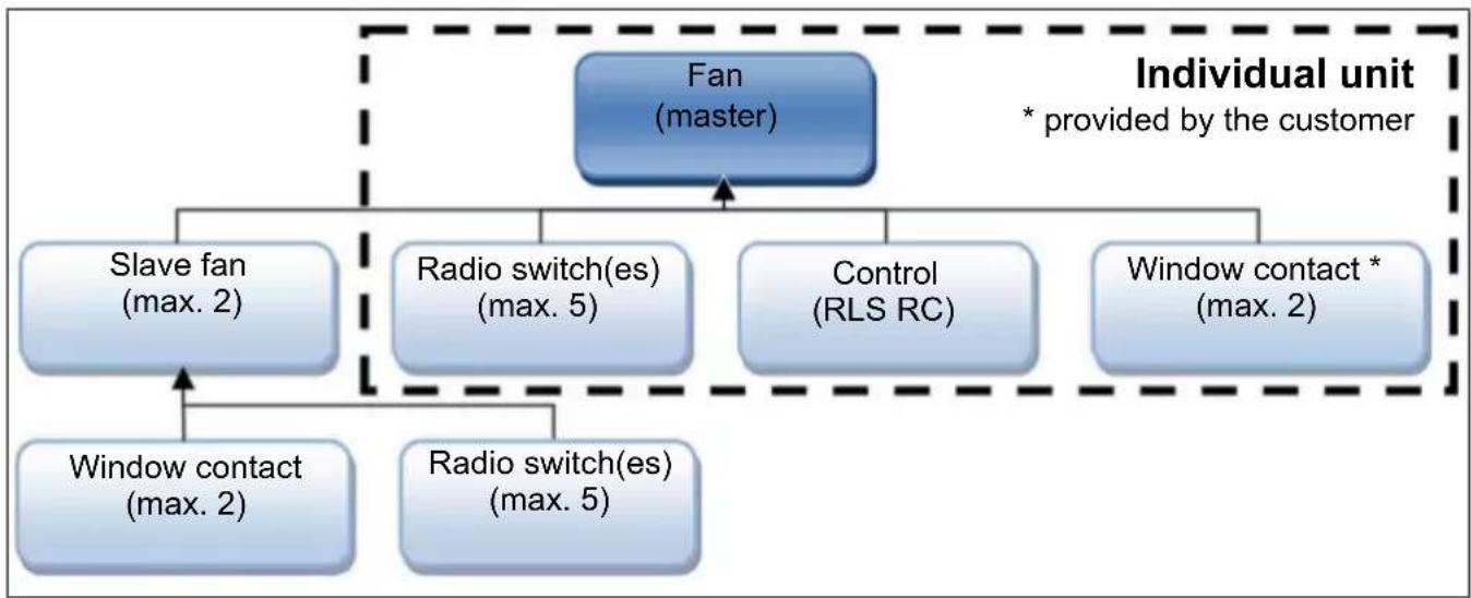
The prescribed minimum distances to the wall and the ceiling shown in the figure must be observed.
- Make sure the housing has a level base.
- Fit wall breakthrough or drill core hole: Minimum diameter, 150~mm
Recommendation: Fit WH 150 wall sleeve. Fit a wall breakthrough with a minimum diameter of 170~mm - Lay the power cable to the installation location (surface-mounted AP or flush-mounted UP), for distance dimensions see above.
7.2 Ceiling
- Perform installation preparations as described in Chapter Wall.
NOTICE Danger of short-circuits and damage to unit if condensation builds up in the fan housing.
Thermally insulate ventilation ducts properly. Allow for a condensation drain or condensate collector in the riser.
7.3 Duct
- Deburr edges on the inside of the duct.
- Perform installation preparations as described in Chapter Wall.
8 Installation and commissioning
8.1 Fan
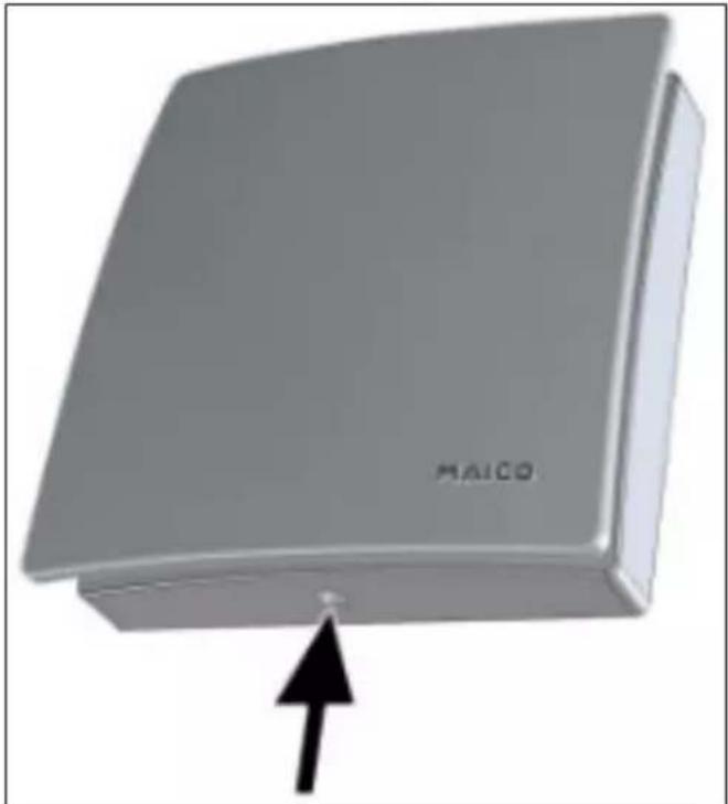
- Unpack unit and take off cover.
- To release the cover, push the catch upwards.
- Fit supplied foam strip centred in socket.
The foam strip must be fitted to the ECA 150 ipro H and KH, so that the units do not draw in any infiltration air from outside.
- For an electrical surface-mounted connection, drill the housing segment [2.1] ( following figure) (011mm)
8.2 Housing installation
NOTICE Damage to unit/functional problems in the event of rubbing impeller.
Do not fit flange sleeve either twisted or crushed.
Make sure that the surface is flat.
- Insert housing into wall breakthrough/wall sleeve (TOP).
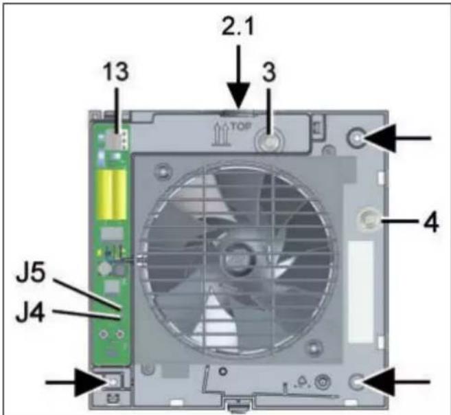
2.1 Housing segment - surface-mounted connection
3 Cable grommet - flush-mounted connection
4 Cable grommet - surface-mounted connection
13 Spring terminal
J4 Jumper J4
J5 Jumper J5
- Align housing horizontally and mark the 3 dowel holes arrows.
- Drill dowel holes with a of 6mm and insert dowels.
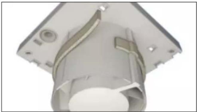
- Carefully press the upper cable grommet out of the housing and remove it. Alternatively, for electrical surface-mounted connection, leave the upper cable grommet in the housing and remove the side cable grommet from the housing.
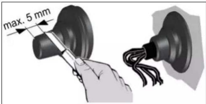
NOTICE Danger of short-circuits / damage to the unit. Water will penetrate if the power cable is incorrectly fed into the fan housing or if the cable grommet is not fitted correctly.
Cut off the cap of the cable grommet so that the cable grommet tightly encloses the power cable. Shorten the cap by a max. of 5 mm.
Fit cable grommet correctly, seal on site if required.
- Insert cable grommet into housing.
- Guide the power cable into the terminal compartment such that the cable grommet fits around the cable sheathing completely.
- Insert housing into wall breakthrough/wall sleeve and secure with 3 screws. Do not insert the housing such that it is twisted or crushed. Make sure you use mounting material which is sized for the purpose.
8.3 Electrical connection
NOTICE Risk of damage to unit in the event of short-circuits.
Insulate PE conductor and individual cable cores that are not required.
Do not touch electric components.
Master-slave operation of RC units is only possible with similar types of ECA 150 ipro RC/RCH/KRC/KRCH units.
- Only lay single cable cores in the fan. To do this, remove the power cable's sheathing in the terminal compartment. Strip single cable cores to 9 to 10mm
- Connect power cable to the spring terminal
The standard model of ECA 150 ipro can be operated in two levels with double switches. Without a double switch, the fan can be operated either at power level 1 or at power level 2 switching variants in chapter.
-
Check the position of the cable grommets. These must provide a good seal.
-
If necessary, connect a speed controller (STX 1,5).
The technology used in the phase angle controller may cause humming noises.
8.4 Operating programs
VZC, KVZC, B and KB: One of the 4 following operating programs can be set with jumpers J4 and J5.
- H and KH: One of the 4 following operating programs can be set with jumpers J4 and J5. The operating program can only be switched on with a switch (light switch). If this is switched on, it takes priority over the automatic humidity function.
- Program: Comfort (= ex works), Demand, Economy and Power.
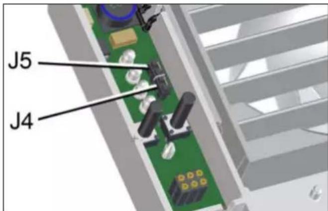
1. Set the desired operating program with jumpers J4 and J5.
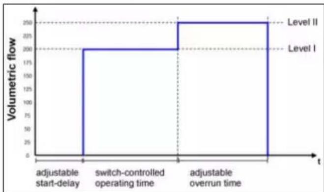
Comfort program
- Power level 1 during room use, power level 2 during overrun time.
J4 bridged, J5 bridged.
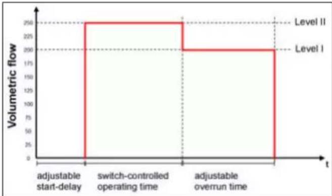
Demand-driven programme
- Power level 2 during room use, power level 1 during overrun time.
J4 open, J5 open
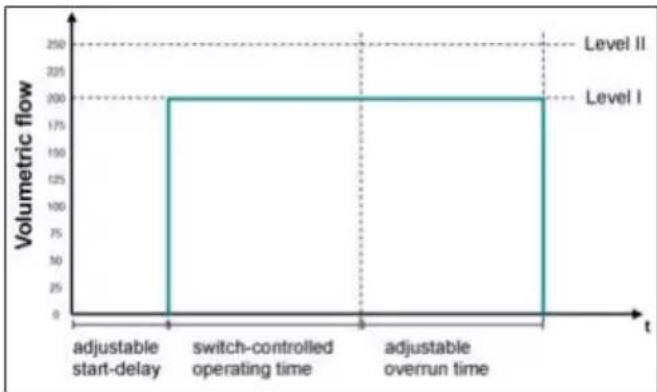
Economy program
- Power level 1 during operation and overrun time.
J4 open, J5 bridged
Power program
- Power level 2 during operation and overrun time.
J4 bridged, J5 open
8.5 Final installation
NOTICE Danger of short-circuits and damage to the unit. Humidity will penetrate if electronics cover is not fitted correctly.
Press electronics cover firmly onto housing such that it is sealed and flush all the way around.
When doing so, do not press setting buttons.
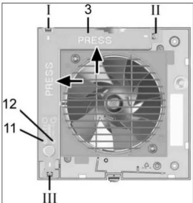
| 3 Electronics cover |
| 11 Setting button for start delay, teach-in button for RC and RCH units |
| 12 Setting button for overrun time/LED (RC units) |
| I-III Housing recesses I, II and III for locking tabs |
- Push the electronics cover onto the 3 locking tabs at the housing recesses I, II and III until the tabs engage. In addition, press the electronics cover firmly into the housing at the positions indicated by the word PRESS.
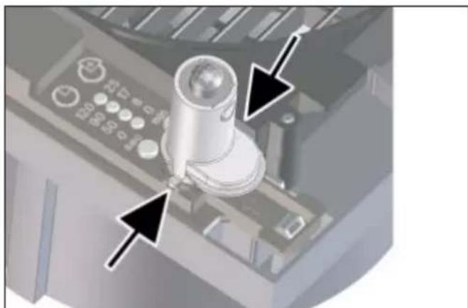
- For unit versions B, KB, H, KH, RCH and KRCH, insert the supplied sensor into the connector socket, in the correct position ( arrows).
H and KH: Do not touch/push on the membrane on the lower side of the sensor wall, otherwise it will be damaged.
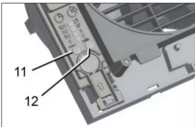
11 Setting button for start delay
12 Setting button for overrun time
- Use the setting keys to set the start delay and/ or overrun time Start delay and overrun time [32].
- On RC, KRC, RCH and KRCH fans, use the left setting button to teach in the radio components Tips for teaching-in radio components [32].
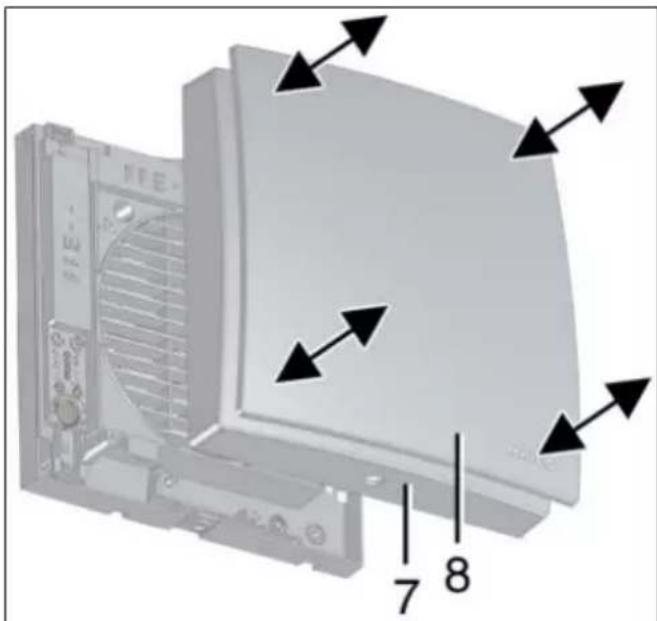
7 Housing cover
8 Designer cover
- Carefully press the housing cover with design cover onto the housing, until they snap into place.
8.6 Commissioning
- Switch the mains fuse on.
-
Run function test.
-
RC, KRC, RCH and KRCH: Teach in radio components Tips for teaching-in radio components [32].
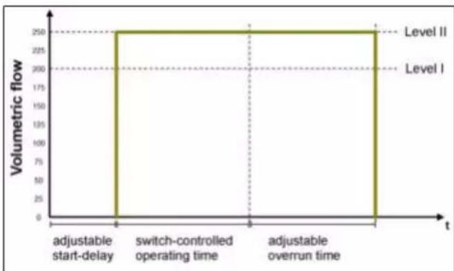
8.7 Start delay and overrun time
To adjust, remove the housing cover and then put it back on.
The first time the setting button is pressed, the currently set value is displayed. During operation the LEDs are off.
For delivery status Product information [23].
1. Carefully remove the housing cover with the design cover.
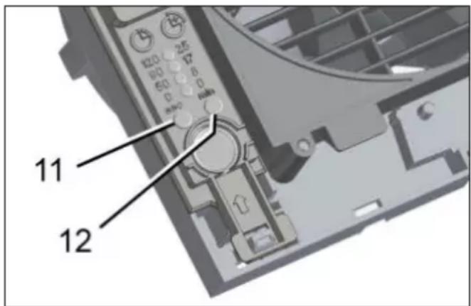
11 Setting button for start delay
12 Setting button for overrun time
Setting the start delay:
- Press the left setting button repeatedly, until the LED of the desired start delay time lights up. Wait until the LED flashes twice and goes out. The value is now saved.
With the H and KH variants, the start delay for the light switch can only be set when the light switch is on.
Setting overrun time:
- Press the right setting button repeatedly, until the LED of the desired overrun time lights up. Wait until the LED flashes twice and goes out. The value is now saved.
The settings take effect starting with the next switching process (sensor, light switch). - Carefully press the housing cover/design cover onto the housing, until they snap into place.
9 Radio components
9.1 Procedure
For information on the function and program levels MAICOsmart system description [26].
To teach in an RC fan, remove the housing cover and then reattach it Preparation for installation [28].
Operation with stand-alone fan
- On the fan, first teach-in the RLS RC room air control and then the radio switches and/or radio window contacts.
- Teach-in further system components.
- Perform function test with all system components.
Master/slave network
- First teach-in the pre-configured RLS RC room air control on the master fan.
- Then teach-in the radio switches, radio window contacts and further slave fans.
- Teach-in radio switches and radio window contacts on the slave fans (max. 2 fans).
- Carefully press the housing cover (incl. designer cover) onto the housing, until it engages with the safety catches.
- Perform function test with all system components.
9.2 Tips for teaching-in radio components
A fan automatically becomes a master if the master fan is set to receive mode and a teach-in telegram is received from a slave fan.
If a master fan is accidentally taught into a slave fan, the master assignment ceases to exist (master fan becomes a slave fan). This can result in having to re-enter all system components.
- A fan becomes a slave fan if it transmits a teach-in telegram to the master unit and the master unit confirms this telegram.
- If the RC master or slave fan receives a valid teach-in telegram from a radio component that has not yet been taught-in, the data is evaluated and stored.
-
If the radio component has already been taught-in, the teach-in telegram is deleted, that means that the teaching-in must be repeated.
-
If there is no reception within 60 seconds, the teaching-in is terminated and the LED on the fan switches off. The procedure must be repeated.
-
Teach-in telegrams from non-supported radio components are ignored.
9.3 Program levels
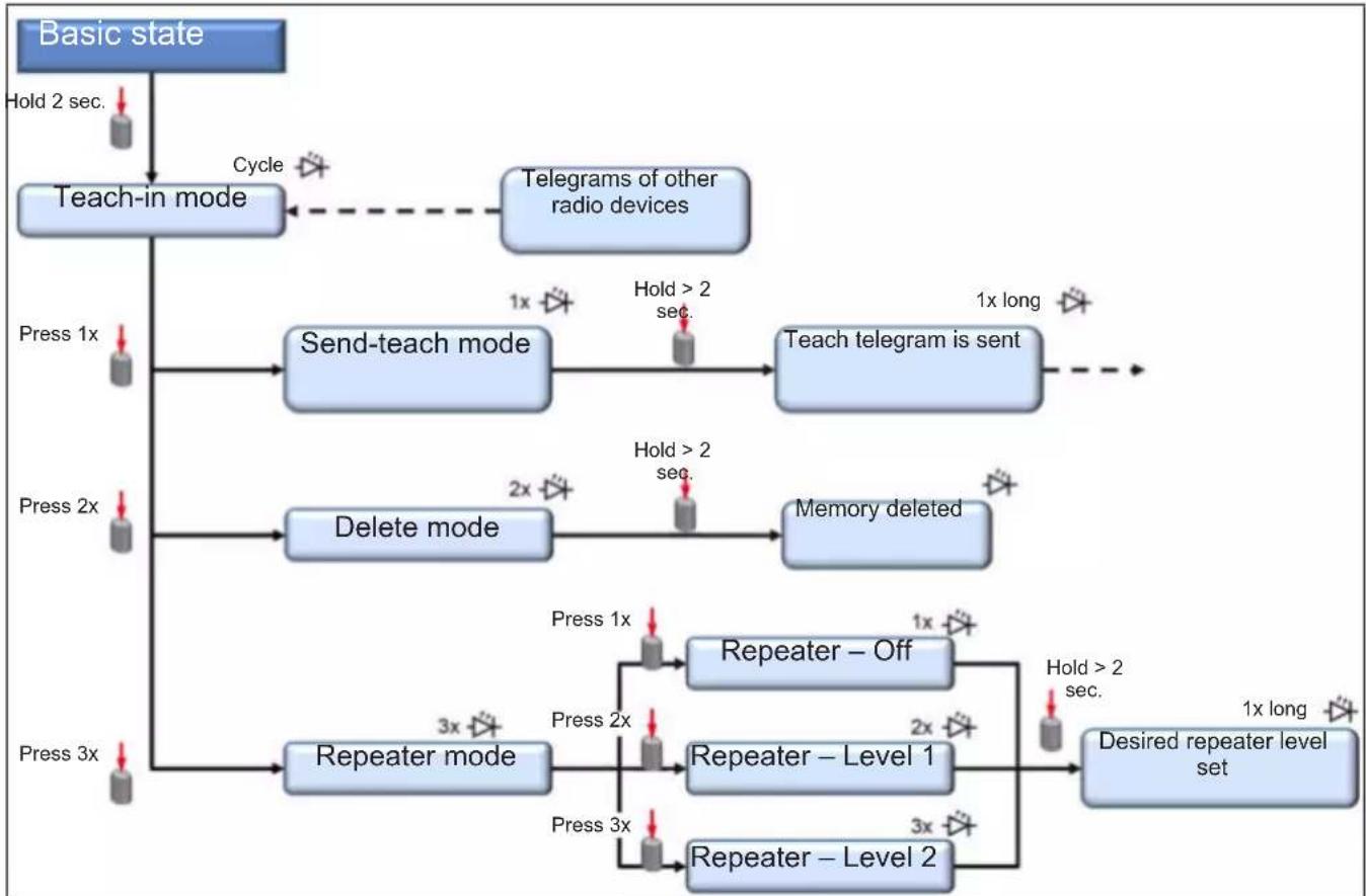
9.4 Switching a receiver to teach-in mode
- Press the teach-in button at least 2 seconds on the receiver fan.
The button LED flashes, teach-in mode is activated.
A teach-in telegram must now be received within 60 seconds. Otherwise, teach-in mode is exited.
9.5 Teaching-in transmitters
When a teach-in telegram is correctly received, the receiver's button's LED lights up for 1 second. The transmitter is now set up.
Teaching-in radio switches
In the case of double-rocket switches (DS RC), both rockers have to be taught-in separately (2 channels).
- Activate teach-in mode on the receiver fan.
LED flashes. Teach-in mode is activated.
- Press the radio switch's right-hand rocker switch 3 times within 2 seconds.
The teach-in telegram is sent. If teaching-in was successful, the LED lights up for approx. 1 second. If transfer was faulty, the button LED flashes briefly 3 times.
-
Reactivate teach-in mode on the receiver fan.
-
Press the radio switch's left-hand rocker switch 3 times within 2 seconds.
The teach-in telegram is sent. If teaching-in was successful, the LED lights up for approx. 1 second. If transfer was faulty, the button LED flashes briefly 3 times.
-
Reactivate teach-in mode on the receiver fan.
-
Press the right-hand rocker switch 3 times within 2 seconds.
The teach-in telegram is sent.
Teaching-in radio window contacts
- Activate teach-in mode on the receiver fan.
The LED flashes, teach-in mode is activated.
- Press the teach-in button on the radio window contact.
The teach-in telegram is sent. If teaching-in was successful, the LED lights up for approx. 1 second. If transfer was faulty, the button LED flashes briefly 3 times.
Teaching-in an RLS RC room air control
The teach-in button is on the rear side of the RLS RC.
- Activate teach-in mode on the receiver fan.
The LED flashes on the fan, the teach-in mode is activated. - Press the RLS RC teach-in button 3 times within 2 seconds.
The teach-in telegram is sent. If teaching-in is completed successfully, the radio icon in the display flashes briefly 3 times. The radio icon is then permanently visible in the display.
The LED on the receiver fan lights up for 1 second upon successful teach-in.
Teaching-in slave fan
- Activate teach-in mode on the master (receiver fan) and a fan that is not yet taught-in (planned slave).
The LED flashes, teach-in mode is activated. - Switch the slave fan to the send mode To do this, press the teach-in button on the slave fan once.
The LED on the slave lights up for a short time and then flashes briefly once. The slave fan is now in Send-learn mode. - Press the teach-in button on the slave fan (>1 second) until the LED on the slave fan lights up briefly once.
The teach-in telegram is sent. If teaching-in is completed successfully, the button LED lights up once for approx. 1.5 seconds. If transfer was faulty, the button LED flashes briefly 3 times. If the teach-in process fails the LED on the slave fan flashes briefly 3 times. The process has to be repeated.
9.6 Deleting transmitters
Deleting an individual transmitter
If there is a transmitter that is faulty or that can no longer be identified, it is possible that all transmitters must be deleted. System components then have to be taught-in again. (This is recommended if a transmitter was lost or is faulty.)
- In order to delete the required transmitter, the transmitter teach-in process (RLS RC, radio switch or window contact) has to be repeated previous chapter.
Deleting all transmitters
- Activate teach-in mode on the master fan (receiver).
The LED flashes, teach-in mode is activated. - Press the teach-in button briefly twice.
LED flashes briefly twice and then goes out. - Press the teach-in button on the slave fan (transmitter) for >1 second until the LED on the fan lights up briefly once.
All taught-in transmitters are deleted. The fan is again in its initial state.
9.7 Setting up the fan as a signal amplifier (Repeater)
The radio electronics in the fan can also be used as a signal amplifier. In this case, the fan that is set up this way works additionally as a signal amplifier. EnOcean telegrams are received and forwarded in parallel to the running application.
This can be necessary for example, with applications in single-family homes that are completely automated with EnOcean products.
Settings values
- Off
- Level 1 = Original telegrams are amplified
- Level 2 = Original telegrams and telegrams that have already been amplified are amplified
Setting up the fan as a signal amplifier
- Activate teach-in mode on the receiver (fan).
The LED flashes, teach-in mode is activated. - Press the teach-in button briefly three times.
The LED lights up briefly and then flashes briefly three times.
3. Press the teach-in button x times for repeater mode:
Repeater off: Push 1 time - LED flashes 1 time
Repeater Level 1: Push 2 times - LED flashes 2 times
Repeater Level 2: Push 3 times - LED flashes 3 times
- Press the teach-in button (≥ 5 seconds) until the LED on the fan lights up once for approx. 1 second.
The setting is saved.
10 Operation
ECA 150 ipro, ECA 150 ipro K
The unit is switched on and off, with a switch to be provided by the customer (double rocker switch for operation with 2 levels). With an on-off switch, operation is also possible either only in the high or only in the low power level (200m^3 /h or 250~m^3 /h)
ECA 150 ipro VZC, ECA 150 ipro KVZC
The unit is switched on and off with a switch to be provided by the customer. Operation then takes place with the set start delay and overrun time according to one of the 4 operating programmes (comfort, demand, economy or power programme). The power level sequence is defined in the respective operating programme.
ECA 150 ipro H, ECA 150 ipro KH
The unit is barrier-free and ventilates according to automatic humidity function with power level 1 or 2. At low humidity, the unit switches off completely. Alternatively, the unit can also be switched on and off with a switch to be provided by the customer (priority over the automatic humidity function). Operation then takes place with the set start delay and overrun time according to one of the 4 operating programmes (comfort, demand, economy or power programme). The power level sequence is defined in the respective operating programme.
ECA 150 ipro B, ECA 150 ipro KB
The unit is barrier-free and vents via automatic movement, according to one of the 4 operating programmes. If no movement is identified, it switches off completely after the set overrun time. Alternatively, the unit can also be switched on and off with a switch to be provided by the customer (priority over the automatic movement). Operation then takes place with the set overrun time (no start delay) according to one of the 4 op
erating programmes (comfort, demand, economy or power programme). The power level sequence is defined in the respective operating programme.
ECA 150 ipro RC, ECA 150 ipro KRC
The unit is switched on/off either at the RLS RC room air control, with the DS RC radio switch, or with a radio window contact to be supplied by the customer.
ECA 150 ipro RCH, ECA 150 ipro KRCH
The unit is barrier-free. Air extraction takes place according to the automatic humidity function. At low humidity levels, the unit switches into the power level activated before humidity operation.
RLS RC programme for ECA 150 ipro RC/KRC/ RCH/KRCH (single-type system)
RLS RC programme P1
Table 1:Programme P1
| System level | ||||
| 1 2 3 | 4 | |||
| Master Off | Power | level 1 | Power level 1 | Power level 2 |
| Slave(s) Off | Off Power | level 1 | Power level 1 | |
RLS RC programme P2
Table 2:Programme P2
| System level | ||||
| 1 2 3 | 4 | |||
| Master Off | Power | level 2 | Power level 1 | Power level 2 |
| Slave(s) Off | Off Power | level 1 | Power level 2 | |
Power level 1 = 200m^3 /h / Power level 2 = 250 m^3 /h (free outlet specifications)
11 Maintenance
The unit is maintenance-free.
12 Cleaning
Clean fan regularly, especially after it has not been used for a long time.
NOTICE Risk of damage to unit if incorrect cleaning agent is used.
Only clean the cover using water.
Do not use aggressive cleaning agents.
NOTICE Lamellae may break if cleaned incorrectly.
Be careful when cleaning them.
Do not open, close or bend the lamellae too much.
- Switch off mains fuse, secure against being accidentally switched back on and position a warning sign.
- Only use a dry cloth to clean the internal parts of the fan.
- If the cover is very dirty, carefully remove it and clean with water.
- Fit cover. Make sure that the 4 studs engage correctly in the cover Final installation [30].
- Switch on mains fuse, remove warning sign, carry out function test.
13 Fault rectification
Fault finding only by qualified electrician. Call on the services of a qualified electrician any time there is a fault. Repairs should only be carried out by a qualified electrician.
Switch off mains fuse, secure against being accidentally switched back on and position a warning sign.
Fault Cause, measures
| Fan does not switch on. | • Start delay approx (max. 120 seconds). Wait for start delay and reduce if necessary. • No mains voltage. Check whether the mains fuse has failed. Switch on if necessary. • Impeller is blocked. Should only be carried out by a trained specialist: Check impeller and clean if necessary. • Motor too hot. Motor's thermal overload protection switches the fan off. Wait until the motor has cooled down. Cool-down time can be up to 60 minutes. Unit switches back on automatically after cooling down. |
| Fan does not switch off. | • Overrun time (max. 25 min.). Wait for overrun time and reduce if necessary. |
| Lamellae do not open or close for K units. | • Lamellae very dirty or blocked. Clean lamellae. |
- Check whether there are any objects between the lamellae. If so, remove them.
- Check whether the wiring is correct according to the wiring diagram. Attach jumper between terminals 1 and 2.
14 Spare parts
Spare parts may only be sourced from and fitted by a specialist installer.
| Designation Article no. | |
| Circuit boards * | |
| PL ECA 150 ipro E101.14 | 1410.0000 |
| PL ECA 150 ipro K E101. | 1413.0000 |
| PL ECA 150 ipro VZC/H/B | E101.1411.0002 |
| PL ECA 150 ipro RC E101. | 1.1412.0001 |
| Electronics covers | |
| ABDE ECA 150 ipro 1 E059.1510.0001 | |
| ABDE ECA 150 ipro 2 E059.1510.9001 | |
| Covers | |
| ABD ECA 150 ipro E059. | 1502.9001 |
| Cover, complete for B variants | 0059.1502.9100 |
| Sensors | |
| SE ECA 150 ipro B E157. | .0145.0000 |
| SE ECA 150 ipro H E157. | .0146.0000 |
| Shutter frame | |
| KR ECA 150 ipro E059.1 | 503.9100 |
- Observe the following videos for replacing the circuit boards:
Replacement of circuit board PL ECA 150 ipro VZC/H/B/RC

Replacement of PL ECA 150 ipro and PL ECA 150 ipro K

In case of questions, please contact:
Spare parts can be ordered at www.shop.maicoventilatoren.com.

15 Dismantling
Dismantling only permitted by a qualified electrician.
- Remove covers.
- Remove the electronics cover.
- Remove power cable.
- Remove fan.
16 Environmentally responsible disposal
Old devices and electronic components may only be dismantled by specialists with elec
trical training. Proper disposal avoids detrimental impact on people and the environment and allows valuable raw materials to be reused with the least amount of environmental impact.
Do not dispose of the following components in household waste!
Old devices, wearing parts (e.g. air filter), defective components, electrical and electronic scrap, environmentally hazardous liquids/oils, etc. Dispose of them in an environmentally friendly manner and recycle them at the appropriate collection points ( Waste Management Act).
- Separate the components according to material groups.
- Dispose of packaging materials (cardboard, filling materials, plastics) via appropriate recycling systems or recycling centres.
- Observe the respective country-specific and local regulations.
Acknowledgements
Maico Elektroapparate-Fabrik GmbH. Translation of the original operating instructions. Misprints, errors and technical changes are reserved. The brands, brand names and protected trademarks that are referred to in this document refer to their owners or their products.
Speed adjustable with STX 1.5
Speed adjustable with STX 1.5
Speed adjustable with TRE...