AHD60PERI - Basket AYA - Free user manual and instructions
Find the device manual for free AHD60PERI AYA in PDF.

| Product type | Range hood |
| Brand | AYA |
| Model | AHD60PERI |
| Power supply | 220-240 V ~ 50/60 Hz |
| Motor power | 65 W |
| Lighting power | 2 x 2 W (total 4 W) |
| Total power | 69 W |
| Max airflow | 288,5 m³/h |
| Noise level | ≤ 64 dB |
| Dimensions (W x D x H) | 595 x 320 x 675-1055 mm |
| Minimum distance to cooking surface | 650 mm (electric) / 750 mm (gas) |
| Exhaust duct diameter | 150 mm |
| Exhaust mode | External extraction or recirculation (charcoal filter) |
| Grease filter | Metal, washable every month |
| Charcoal filter | Optional, replace at least once a year |
| Speeds | 3 speeds (Low, Medium, High) + Stop |
| Lighting | LED 2 W, average illuminance 137 lux |
| Energy efficiency index | 79,8 |
| Annual consumption | 41 kWh/year |
| Legal warranty | 2 years (conformity) |
| Spare parts availability period | 2 years |
Frequently Asked Questions - AHD60PERI AYA
User questions about AHD60PERI AYA
0 question about this device. Answer the ones you know or ask your own.
Ask a new question about this device
Download the instructions for your Basket in PDF format for free! Find your manual AHD60PERI - AYA and take your electronic device back in hand. On this page are published all the documents necessary for the use of your device. AHD60PERI by AYA.
USER MANUAL AHD60PERI AYA
MANUEL D'UTILISATION AHD60 PERI
FR
natural_image
Black industrial kitchen air conditioner unit with two recessed lighting fixtures (no visible text or symbols)HOTTE DECORATIVE
TABLE DES MATIERES
CONSIGNES DE SECURITE IMPORTANTES -1-
DESCRIPTION DE L'APPAREIL -10-
INSTRUCTIONS DU MONTAGE MURAL -12-
UTILISATION DE L'APPA REIL 17
NETTOYAGE ET ENTRETIEN
GUIDE DE DEPANNAGE
natural_image
Abstract icon of a person moving with arrows, enclosed in a circle (no text or symbols)LE TRI

FACILE
flowchart
graph LR
    A["Worker Icon"] --> B["LED"]
    B --> C["LED"]
    C --> D["Output"]
natural_image
Diagram of airflow around a mechanical structure with directional arrows indicating movement (no text or symbols)natural_image
Illustration of a hand holding a cable with an open electrical outlet, showing a right-hand rule (no text or symbols present)natural_image
Line drawing of a kitchen appliance mounted on a brick wall, with no visible text or symbolsnatural_image
Simple line drawing of a refrigerator with a hanging screen and arrow indicating motion (no text or symbols)natural_image
Simple line drawing of a rectangular box with a smaller 3D cube below, showing internal lines and arrows (no text or symbols)natural_image
Diagram of a brick wall with diagonal bracing and upward arrows indicating direction (no text or symbols)natural_image
Diagram of a mechanical or fluid system with directional arrows indicating flow or movement (no text or symbols)natural_image
Two-step diagram showing hand positioning of a flat object on a surface, with no text or symbols present.natural_image
Technical line drawing of a mechanical fan or motor assembly with no visible text or symbolsRemarque:
flowchart
graph TD
    A["①: Assembly Box"] --> B["②: Internal Component"]
    B --> C["③: Outlet of Plate"]
    C --> D["④: After relâcher, before/after relâchement"]
    D --> E["⑤: Final Assembly Box with FR-19 component"]
    E --> F["⑤: Outlet of Plate"]
natural_image
Symbol of a trash bin crossed with a diagonal line, no text or numbers presentnatural_image
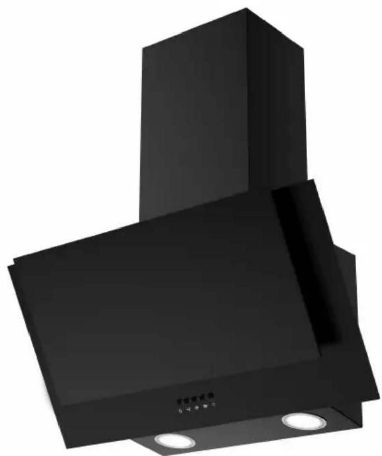
Black industrial chimney with two circular flamps, no visible text or symbols on the main structure.COOKER HOOD
TABLE OF CONTENTS
IMPORTANT SAFETY INSTRUCTIONS -1-
PARTS & DESCRIPTIONS -8-
WALL MOUNTING INSTALLATION -10-
OPERATION -15-
MAINTENANCE -16-
TROUBLE SHOOTING -18-
TECHNICAL SPECIFICATIONS -19-

THIS PRODUCT IS FOR HOUSEHOLD USE ONLY!
Please read these instructions carefully before the first use of this product and save this manual for your future reference.
Before using the appliance for the first time, remove all packaging and protective polythene film.
IMPORTANT SAFETY INSTRUCTIONS
When using electrical appliances, basic safety precaution should always be followed, including the following:
- These instructions are for your safety. Please read through them thoroughly prior to installation.
- This appliance has been designed for use as an exhausting (air evacuation to the outside) or filtering (indoor air re-cycling) hood.
- All installation work must be carried out by a competent person or qualified electrician.
- This appliance must be installed correctly by a
suitably qualified person, strictly following the manufacturer's instructions.
- WARNING: Accessible parts may become hot during use.
- Young children should be kept away. Care should be taken to avoid touching the appliance.
- The Manufacturer highly recommends that this appliance be kept out of the reach of babies and small children.
- This appliance can be used by children aged from 8 years and above and persons with reduced physical, sensory or mental capabilities or lack of experience and knowledge if they have been given supervision or instruction concerning use of the appliance in a safe way and understand the hazards involved. Children shall not play with the appliance. Cleaning and user maintenance shall not be made by children without supervision.
- Keep the appliance and its cord out of reach of children less than 8 years.
- Means for disconnection must be incorporated in the fixed wiring in accordance with the wiring rules. An all-pole disconnection switch having a contact separation of at least 3 mm in all poles should be connected in fixed wiring.
- Regularly check the power plug and power cord for damage. If the supply cord is damaged, it must be replaced by the manufacturer, its service agent or similarly qualified persons in order to avoid a hazard.
- Do not allow the electric cables to touch the hot parts of the appliance.
- Make sure that the power cord is not caught under or in the appliance and avoid damage to the power cable.
- Do not install the appliance outdoors in a damp place or in an area which may be prone to water leaks such as under or near a sink unit. In the event of a water leak allow the machine to dry naturally.
- Do not use flammable sprays in close vicinity to the appliance.
- Please dispose of the packing material carefully.
- Do not use flammable sprays in close vicinity to the appliance.
- We also recommend that great care be taken during use and cleaning. Read the cleaning and maintenance sections for
this appliance carefully.
- A steam cleaner is not to be used.
- The appliance is not intended to be operated by means of external timer or separated remote-control system.
Warning: Consult local regulations regarding fumes outlets. Do not connect the hood to a fume, ventilation or hot air duct. Confirm that room ventilation is appropriate with the local authorities.
Make sure the maximum air extraction flow rate for the appliances in the room does not exceed 4 Pa (0.04 mbar). The room must have adequate ventilation if an extractor hood is used simultaneously with appliances that run on gas or other fuels.
The air must not be discharged into a flue that is used for exhausting fumes from appliances burning gas or other fuels.
Regulations regarding air extraction must be complied with.
Warning: Before connecting the hood: switch off the electricity supply and check that the supplied voltage and frequency coincide with that indicated on the
appliance nameplate.
Warning: The hood may stop working during an electrostatic discharge (e.g. lightning). This involves no risk of damage. Switch off the electricity supply to the hood and reconnect after one minute.
- To avoid the risk of fire, clean the metal filter regularly and closely watch and regulate pans containing hot oil.
- Do not use the hood if it shows signs of damage or imperfection. Contact customer services.
- Flambe cooking must not be carried out underneath this appliance.
- When installing the appliance, make sure that the following distances between the top of cooker or hob and the lowest part of the cooker hood must be observed:
Gas hobs: 750mm.
Electric hobs: 650mm.
Warning There is a risk of electric shock and fire if cleaning is not carried out in accordance with the instructions.
Warning: For safety reason, please use only the same size of fixing or mounting screw which are recommended in this instruction manual.
Warning: Failure to install the screws or fixing device in accordance with these instructions may result in electrical hazards.
Electrical Shock Hazard
Only plug this unit into a properly earthed outlet. If in doubt seek advice from a suitably qualified engineer.
Failure to follow these instructions can result in death, fire, or electrical shock.
LAMP
The available lamps and the correspondence ILCOS D codes and lamp pictures:
Use type lamp (or use in alternative type lamp) DBR-2-H-68 (ILCOS D code in according to standard IEC 61231).
- Self-ballasted fluorescent reflector lamp - Integral induction type ballast
- Max wattage: 2W
- Voltage range: 220-240V\~ 50-60Hz
- Dimensions
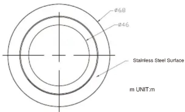
If the supply LED bulb is damaged, it must be replaced by the manufacturer, its service agent or similarly qualified persons in order to avoid a hazard.
flowchart
graph LR
    A["LED"] --> B["Worker Icon"]
    B --> C["LED"]
    C --> D["Square"]
This product contains a light source of energy efficiency class
PARTS & DESCRIPTIONS
| Part Diagram | Pieces | |
| Main Body | 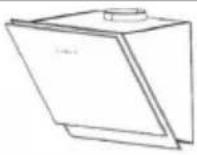 | 1 |
| Aluminium Duct |  | 1 |
| Cooker hood bracket | 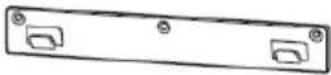 | 1 |
| Upper Chimney Bracket | 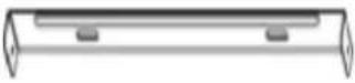 | 1 |
| Lower Chimney Bracket | 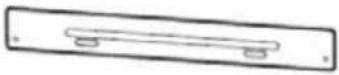 | 1 |
| Screw (4x30mm) | 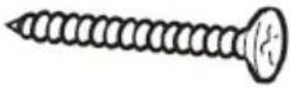 | 9 (2 for spare use) |
| Screw (4 x 8mm) | 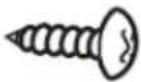 | 6 (2 for spare use) |
| Wall Plug | 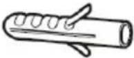 | 9 (2 for spare use) |
| Carbon Filter | 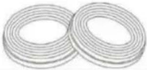 | 2 |
| Chimney | 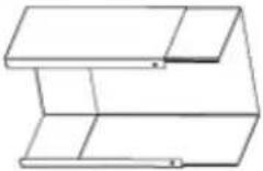 | 2 |
| Cable tie |  | 1 |
| aluminum tape | 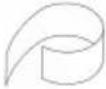 | 1 |
Installation drawing(Line Drawing)
MODEL: AHD60PERI
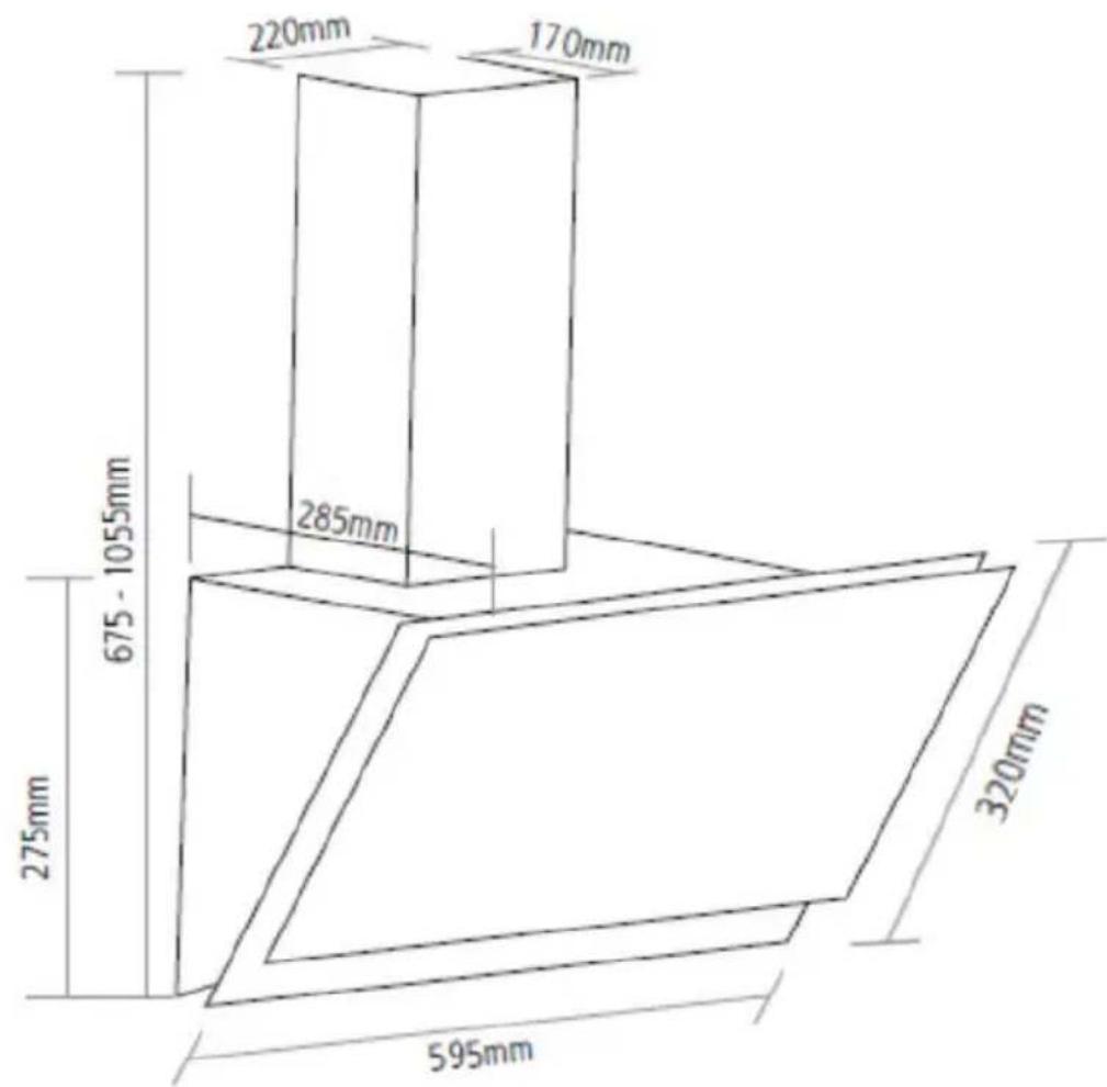
Prepare for installation:
- If you have an outlet to the outside, your cooker hood can be connected as below picture by means of an extraction duct (enamel, aluminum, flexible pipe or inflammable material with an interior
diameter of 150mm)
natural_image
Diagram of airflow around a mechanical structure with directional arrows indicating movement (no text or symbols)- Before installation, turn the unit off and unplug it from the outlet.
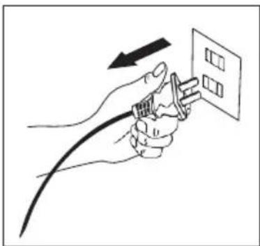
natural_image
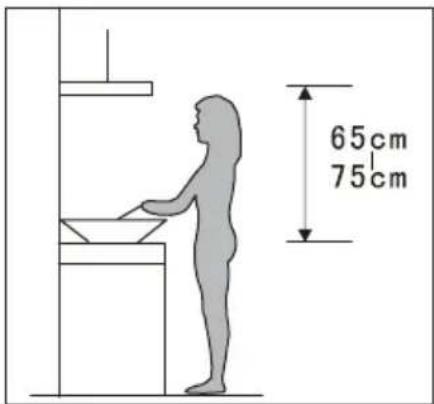
Illustration of hands connecting a cable to a wall-mounted panel with an arrow indicating direction (no text or symbols)- The cooker hood should be placed at a distance of 65\~75cm above the cooking plane for best effect.
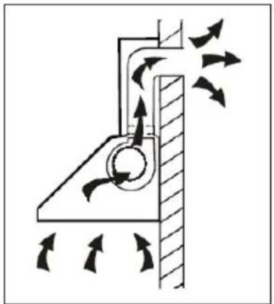
Installation (Vent outside):
Attention! Observe the warning in the instruction sheet concerning the operation of the appliance when air is discharged from the room.
When the range hood and appliance supplied with energy other than electricity are simultaneously in operation, the negative pressure in the room must be not exceed 4 Pa ( 4 × 10^-5 Bar)
- Drill 3 x 8mm holes to accommodate the bracket. Screw and tighten the bracket onto the wall with the screws & screw plugs provided.
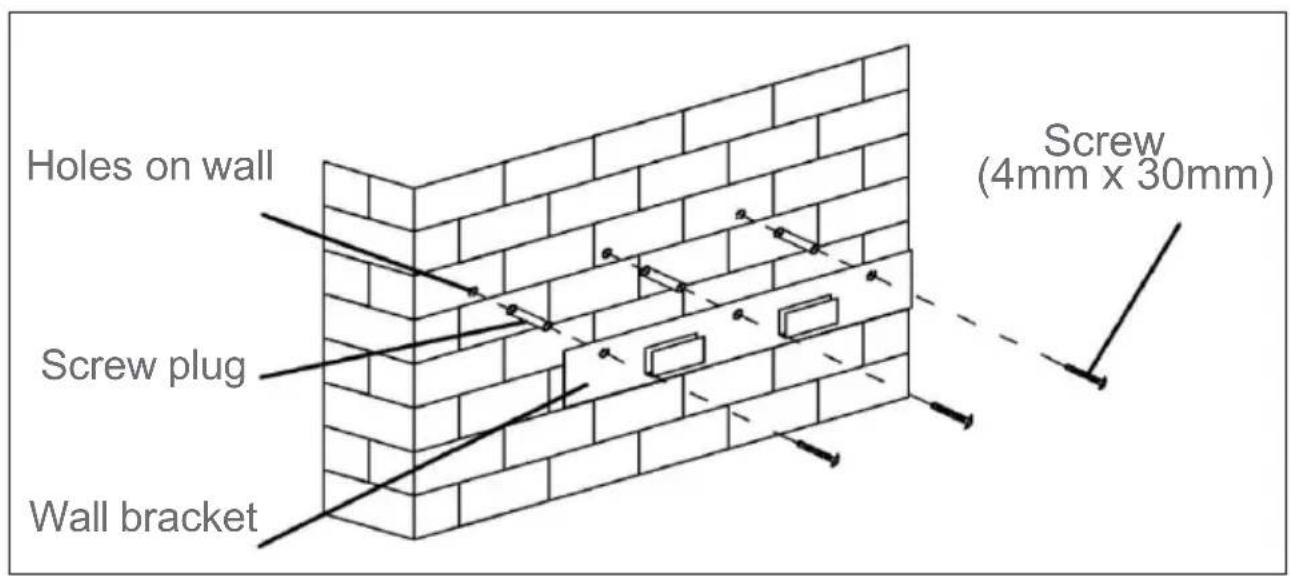
- Offer up the cooker hood and hang onto the wall bracket hook.

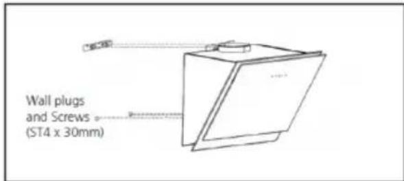
natural_image
Line drawing of a kitchen appliance mounted on a brick wall, with no text or symbols present.After hanging the hood on the bracket, remove the grease filters, mark 2 holes inside the hood for safety screws. After marking, remove the hood, drill two holes and insert 2 wall plugs and finally fix the safety screws with 2 screws (ST4x30mm).
- Place the plastic duct on the cooker hood.
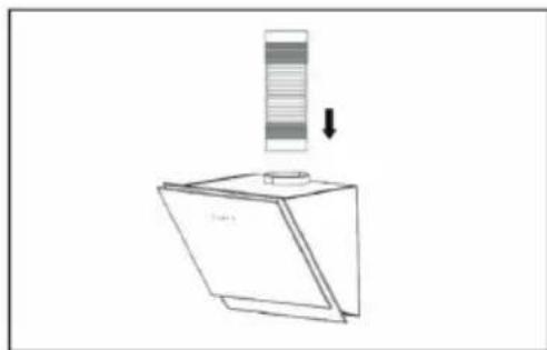
natural_image
Simple line drawing of a box with a vertical striped object above it and a downward arrow, no text or symbols present.provided with an adhesive tape&a plastic string to fix the aluminium pipe.
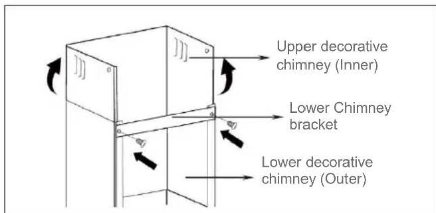
- The lower chimney bracket is used to fix the upper decorative chimney and lower decorative chimney.
Use 2pcs 4x8mm screws to attach lower chimney and lower chimney bracket together. Put the lower chimney on the cooker hood and mark the location of lower chimney bracket fixing holes on the wall.
Noted: Do not fasten screws too much, make sure upper decorative chimney can be telescopically adjusted after assembled.
EN-12
Put the chimney on the cooker hood. Fix the lower chimney bracket on the wall by 2 screws (4mm x30mm).
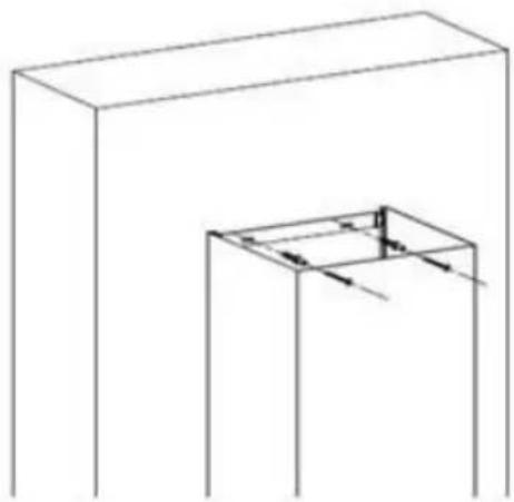
natural_image
Simple line drawing of a rectangular box with a smaller 3D cutout showing internal arrows (no text or symbols)Then pulling out the upper chimney upwards to the target height. Adjust to reach the height required.
Fix the upper chimney on the upper chimney bracket by 2 screws (4x8mm). Then fix the upper chimney bracket on the wall. Before fixing the bracket on the wall, you can decide the upper chimney bracket fixing holes for installation.
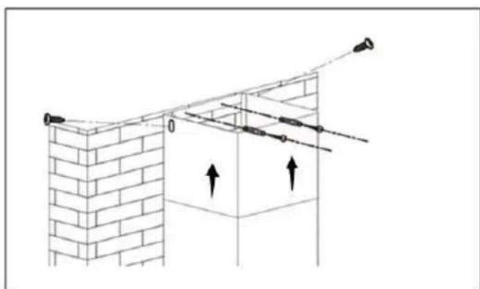
natural_image
Diagram of a brick wall with diagonal braces and upward arrows indicating direction (no text or symbols)Warning: For safety reason, please use only the same size of fixing or mounting screw which are recommended in this instruction manual.
Warning: Failure to install the screws or fixing device in accordance with these instructions may result in electrical hazards.
Installation (Vent inside)
If you do not have an outlet to the outside, exhaust pipe is not required and the installation is similar to the one show in section "Installation (Vent outside)".
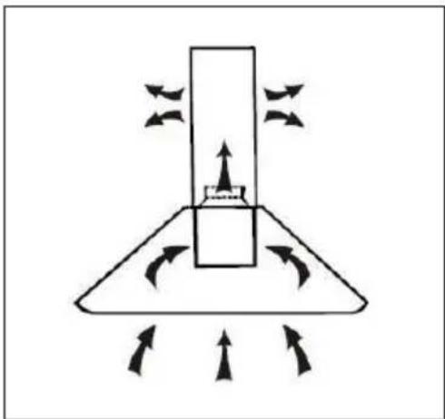
natural_image
Diagram of a mechanical or fluid system with directional arrows indicating flow or movement (no text or symbols)Activated carbon filter can be used to trap odors.
In order to install the activated carbon filter, the grease filter should be detached first. Press the lock and pull it downward.
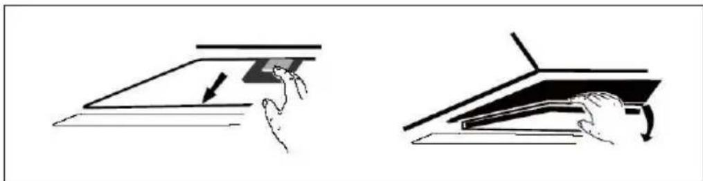
natural_image
Two-step diagram showing hand positioning and folding of a rectangular object, no text or symbols presentPlug the activated carbon filter into the unit and turn it in clockwise direction. Repeat the same on the other side.
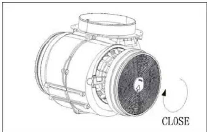
natural_image
Technical line drawing of an electric motor with a close button and fan blade (no text or symbols)NOTE:
oMake sure the filter is securely locked. Otherwise, it would loosen and cause dangerous.
oWhen activated carbon filter attached, the suction power will be lower.

It's used for turning on/off the fan.

Low Speed button
It's used for Ventilation on the kitchen. It is suitable for simmering and cooking which do not make much steam.

Medium Speed button
Airflow speed is ideally for ventilation in standard cooking operation.

High Speed button
When high density of smoke or steam produced, press high-speed button for highest effective ventilation.

Light button
Regarding the instructions for the replacement of the bulb, cleaning and maintenance of the appliance, please refer to below paragraphs of this manual.
Attention! Before cleaning switch the unit off and pull out the plug.
I. Regular Cleaning
Use a soft cloth moistened with hand-warm mildly soapy water or household cleaning detergent. Never use metal pads, chemical, abrasive material or stiff brush to clean the unit.
II. Monthly Cleaning for Grease Filter
ESSENTIAL: Clean the filter every month can prevent any risk of fire.
The filter collects grease, smoke and dust..... so the filter is directly affecting the efficiency of the cooker hood. If not cleaned, the grease residue (potential flammable) will saturate on the filter. Clean it with household cleaning detergent.
III. Annual Cleaning for Activated Carbon Filter
Apply SOLELY to unit that installed as a recirculation unit (not vented to the outside).
This filter traps odours and must be replaced at least once a year depending on how frequent the cooker hood used.
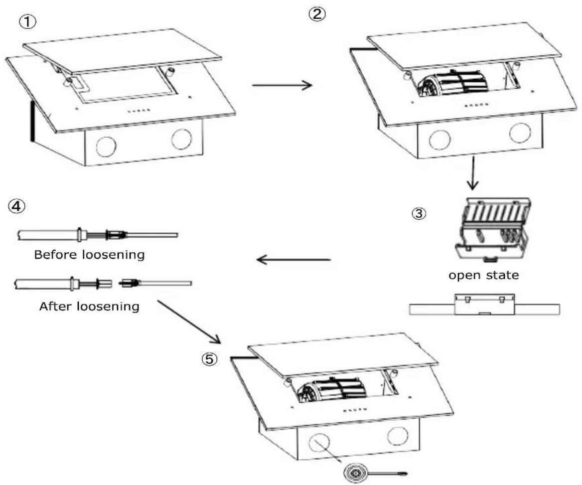
I.Bulb Replacement
Operated by professionals with the same specification lamps:
II.Open the decorative plate.
III. Take out the filter.
IV. Find the protective sleeve of the high pressure lamp connector in the case and open it.
V. Release the connection plug between the LED light and the high-voltage line.
VI.Push the LED light out of the cabinet to replace it.
ATTENTION: Make sure the bulb is completely cool before replacing it.
flowchart
graph TD
    A["①: Top-down device"] --> B["②: Top-down device with internal components"]
    B --> C["③: Open state with internal components"]
    C --> D["④: After loosening, first component is labeled 'Before loosening'"]
    D --> E["⑤: Bottom-down device with internal components on top"]
    E --> F["⑤: Right end with circular button"]
EN-17
| Fault | Cause | Solution |
| Light on, but fan does not work | The fan blade is jammed. | Switch of the unit and repair by qualified service personnel only. |
| The motor is damaged. | ||
| Both light and fan do not work | light bulb burn. | Replace the bulb with correct rating. |
| Power cord looses. | Plug in to the power supply again. | |
| Serious Vibration of the unit | The fan blade is damaged. | Switch of the unit and repair by qualified service personnel only. |
| The fan motor is not fixed tightly. | Switch of the unit and repair by qualified service personnel only. | |
| The unit is not hung properly on the bracket. | Take down the unit and check whether the bracket is in proper location. | |
| Suction performance not good | Too long distance between the unit and the cooking plane | Readjust the distance to 65-75cm |
| Model | AHD60PERI |
| Voltage / Frequency | 220-240V~ 50-60Hz |
| Rated motor input power | 65W |
| Illumination | ≤2X2W |
| Rated input power | 69W |
| Air flow | ≤288.5m3/h |
| Noise | ≤64dB |
| Symbol | Valeur | Unit | |
| Model identification | — | AHD60PERI | — |
| Annual Energy Consumption | AEC_hood | 41 | kWh/a |
| Time increase factor | f | 1.7 | — |
| Fluid Dynamic Efficiency | FDE_hood | 9.5 | — |
| Energy Efficiency Index | EEI_hood | 79.8 | — |
| Measured airflow rate at the best efficiency | Q_BEP | 168.8 | m3/h |
| Measured air pressure at best efficiency point | P_BEP | 124 | Pa |
| Maximum airflow | Q_max | 288.5 | m3/h |
| Measured electric power input at best efficiency point | W_BEP | 61.1 | W |
| Nominal power of the lighting system | W_L | 4 | W |
| Average illumination of the lighting system on the Cooking surface | Emiddle | 137 | lux |
| Measured power consumption on standby mode | P_S | — | W |
| Measured power consumption on off mode | P_O | 0 | W |
| Sound power level | L_WA | 64 | dB |
| Light Efficiency | LE_hood | 34.2 | Lux/w |
- The above table indicate the information for the cooker hood. The test result is done as per the relevant requirement of EU No 65/2014 and EU No 66 / 2014.
ENVIRONMENTAL PROTECTION:
natural_image
Symbol of a trash bin crossed with a diagonal line, representing no waste or elimination (no text or numbers present)European directive 2012/19/EU on Waste from Electrical and Electronic Equipment (WEEE), requires that used household appliances are not thrown into the normal municipal waste stream. Used appliances must be collected separately in order to optimize the rate of recovery and recycling of materials that compose them, and to reduce the impact on human health and on the environment. The crossed bin symbol is affixed to all the products to remind you of the obligations of separated collection.
We decline liability for any damage or accident derived from any use of this product which is not in conformity with the instructions contained in this booklet.
In accordance with Article L. 217 of the Consumer Code, your product benefits from a legal guarantee of of conformity of 2 years.
Duration of availability of spare parts: 2 years.
To contact our After-Sales Service, before going to your BUT store, call 09 78 97 97 97,
From Monday to Saturday from 8:00 am to 8:00 pm (local call price).