BBC 25/1 - Grass trimmer Bavaria - Free user manual and instructions
Find the device manual for free BBC 25/1 Bavaria in PDF.

User questions about BBC 25/1 Bavaria
0 question about this device. Answer the ones you know or ask your own.
Ask a new question about this device
Download the instructions for your Grass trimmer in PDF format for free! Find your manual BBC 25/1 - Bavaria and take your electronic device back in hand. On this page are published all the documents necessary for the use of your device. BBC 25/1 by Bavaria.
USER MANUAL BBC 25/1 Bavaria
GB Original operating instructions Petrol Power Scythe
natural_image
Pure diagram of a curved line with two arrows pointing downward, no text or symbols present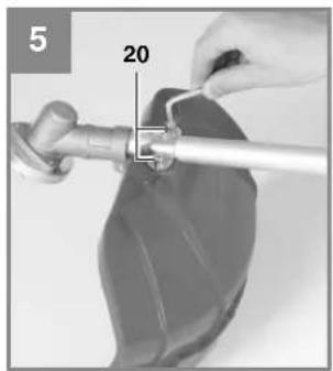
natural_image
Close-up of hands holding a tool with a numbered component (20), no visible text or symbols
text_image
6a 18 22232425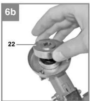
natural_image
Close-up of a hand holding a mechanical component with a circular housing and labeled part '22' (no text or symbols beyond label)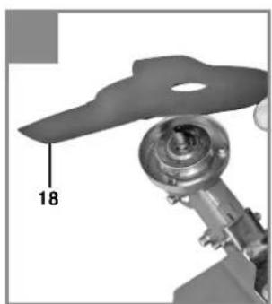
natural_image
Mechanical assembly diagram showing a component with a numbered label '18' pointing to a specific part (no readable text or symbols beyond the number)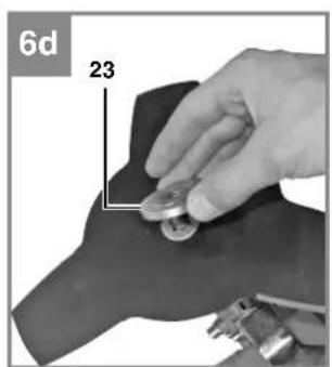
natural_image
Close-up of a hand holding two small round objects on a dark surface, with no visible text or symbols.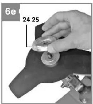
text_image
6e 24 25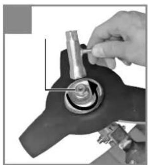
natural_image
Close-up of a hand using a tool to adjust or install a mechanical component (no visible text or symbols)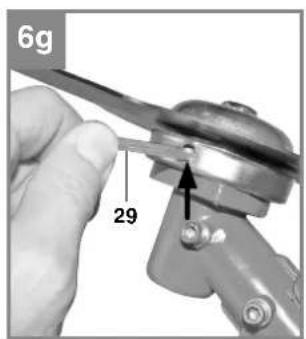
text_image
6g 29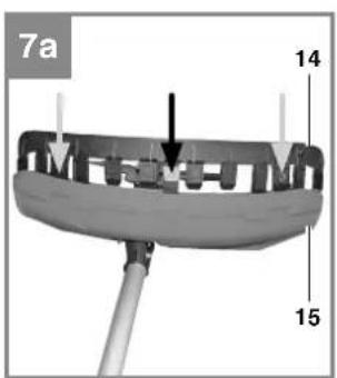
text_image
7a 14 15
text_image
7b 14 15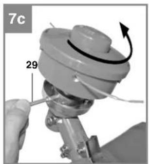
natural_image
Close-up of a mechanical component with a wrench and arrow indicating rotation (no text or symbols)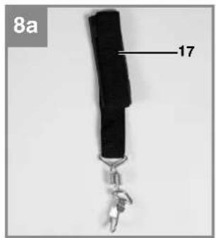
natural_image
Close-up of a black wrist strap with a keychain and labeled part '17' (no text or symbols on the object itself)
natural_image
Person tying a knot using a spring, no visible text or symbols
natural_image
Person holding a metal bar with a spring scale, no visible text or symbols
natural_image
Close-up of a person's belt adjusting a button, showing a black arrow indicating direction (no text or symbols)
natural_image
Close-up of a person's shoulder belt buckle being adjusted, with a hand adjusting the buckle (no visible text or symbols)
natural_image
Person wearing a dark uniform with a black safety harness, standing indoors (no visible text or symbols)
natural_image
Illustration of two workers spraying water with backpacks in a field (no text or symbols)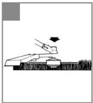
natural_image
Simple line drawing of a hand pressing down on a mechanical device (no text or symbols)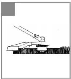
natural_image
Simple line drawing of a mechanical lever or lever assembly (no text or symbols)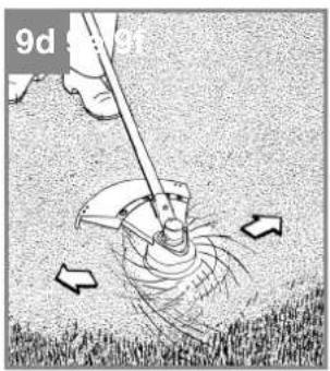
text_image
9d 5g 9f
natural_image
Diagram of a mechanical lever interacting with a surface, showing motion and pivot (no text or symbols)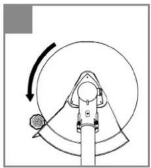
natural_image
Diagram of a mechanical device with rotating arm and curved components (no text or symbols)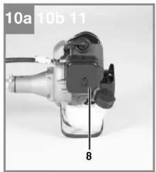
natural_image
Close-up of a mechanical device with labeled parts (8 and 10a, 10b, 11), no readable text or symbols beyond labels.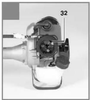
natural_image
Close-up of a mechanical device with labeled component '32' (no readable text or symbols beyond label)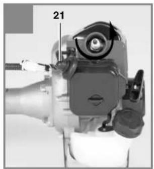
natural_image
Close-up of a mechanical device with a numbered label '21' pointing to a component (no readable text or symbols beyond the number)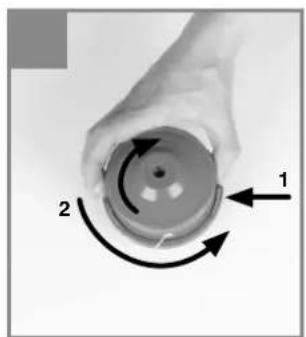
natural_image
Hand holding a circular mechanical component with two curved arrows labeled 1 and 2, indicating rotational motion (no text or symbols beyond labels)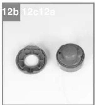
natural_image
Two mechanical bearing components, one circular and one rounded, shown against a plain background (no text or symbols visible)
natural_image
Close-up of hands assembling a mechanical bearing housing (no visible text or symbols)
natural_image
Close-up of hands holding a thin wire or plastic component, no visible text or symbols
natural_image
Close-up of hands holding a small mechanical component with a wire, no visible text or symbols
natural_image
Close-up of a dark mechanical component with a transparent dome and central hole, shown against a plain background (no text or symbols visible)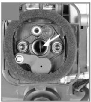
natural_image
Close-up of a mechanical component with no visible text or symbols
text_image
13b13a D C E14


D
Gefahr!
When using the equipment, a few safety precautions must be observed to avoid injuries and damage. Please read the complete operating instructions and safety regulations with due care. Keep this manual in a safe place, so that the information is available at all times. If you give the equipment to any other person, hand over these operating instructions and safety regulations as well. We cannot accept any liability for damage or accidents which arise due to a failure to follow these instructions and the safety instructions.
1. Safety regulations
The corresponding safety information can be found in the enclosed booklet.
Danger!
Read all safety regulations and instructions. Any errors made in following the safety regulations and instructions may result in an electric shock, fi re and/or serious injury.
Keep all safety regulations and instructions in a safe place for future use.
Safety devices
When working with the equipment, the appropriate plastic guard hood for cutting blade mode or cutting line mode must be fitted to prevent objects being thrown out by the equipment. The integrated blade in the cutting line guard hood automatically cuts the line to the optimum length.
Explanation of the warning signs on the equipment (Fig. 14):
- Warning!
- Read the directions for use before operating the equipment.
- Wear protective headgear, goggles and ear muff s.
- Wear sturdy, non-slip footwear.
- Wear safety gloves.
- Protect the equipment from rain and damp.
- Be careful of objects being thrown out!
- Always switch off the equipment and pull out the spark boot plug before carrying out any maintenance work.
- All bystanders must be kept at least 15 m from the machine.
- The equipment continues to rotate!
-
Caution: Hot equipment parts. Keep your distance.
-
Add a little grease (gear grease) after every 20 hours in operation!
2. Layout and items supplied
2.1 Layout (Fig. 1-13)
- Engine assembly
- Long handle assembly
3a. Steady grip on the right
3b. Steady grip on the left - Starter cable
- Choke lever
- Petrol tank
- Fuel pump „primer“
- Air filter housing cover
- On/Off switch
- Throttle lever lock
- Throttle lever
- Throttle lock
- Line spool with cutting line
- Cutting line guard hood
- Cutting blade guard hood
- 4x screws M5 (25 mm)
- Harness
- Cutting blade
- Holder for steady grip
- 6x screws M6 (20 mm)
- Spark plug connector
- Carrier plate
- Pressure plate
- Pressure plate cover
- Nut M10 (left-hand thread)
- Oil/petrol mixing bottle
- Spark plug wrench
- Open-ended wrench 8/10 mm
- Allen key size 4 mm
- Allen key size 5 mm
- 2x cable ties
- Air filter
2.2 Items supplied
Please check that the article is complete as specified in the scope of delivery. If parts are missing, please contact our service center or the sales outlet where you made your purchase at the latest within 5 working days after purchasing the product and upon presentation of a valid bill of purchase. Also, refer to the warranty table in the service information at the end of the operating instructions.
- Open the packaging and take out the equipment with care.
- Remove the packaging material and any
GB
packaging and/or transportation braces (if available).
- Check to see if all items are supplied.
- Inspect the equipment and accessories for transport damage.
- If possible, please keep the packaging until the end of the guarantee period.
Danger!
The equipment and packaging material are not toys. Do not let children play with plastic bags, foils or small parts. There is a danger of swallowing or suff ocating!
• Engine assembly
• Long handle assembly
• Steady grip left + right
• Holder for steady grip
• 6x screws M6 (20 mm)
- Harness
• 4x screws M5 (25 mm)
• Cutting blade
• Line spool with cutting line
- Carrier plate
- Pressure plate
• Pressure plate cover
• Nut M10 (left-hand thread)
• Oil/petrol mixing bottle
- Spark plug wrench
• Open-ended wrench 8/10 mm
• Allen key size 4 mm
• Allen key size 5 mm
- 2x cable ties
• Original operating instructions
• Safety information
• Guard hood for cutting line/cutting blade
3. Proper use
The power scythe (using the cutting blade) is designed for cutting young trees, strong weeds and undergrowth. The power trimmer (using the line spool with cutting line) is designed for cutting lawns, grassed areas and small weeds. The operating instructions as supplied by the manufacturer must be obeyed to ensure that the equipment is used properly. Any use which is not expressly permitted in the manual may result in damage to the equipment and place the user in serious danger. Be sure to observe the restrictions in the safety instructions.
Please note that our equipment has not been designed for use in commercial, trade or industrial applications. Our warranty will be voided if the equipment is used in commercial, trade or industrial businesses or for equivalent purposes.
Important. Due to the high risk of bodily injury to the user, the petrol power scythe must not be used to carry out the following work: to clean dirt and debris off walkways, or to chop up tree or hedge clippings. Similarly, the petrol power scythe must not be used to level out high areas such as molehills. For safety reasons, the petrol power scythe must not be used as a drive unit for other work tools or toolkits of any kind.
The equipment is allowed to be used only for its prescribed purpose. Any other use is deemed to be a case of misuse. The user/operator and not the manufacturer will be liable for any damage or injuries of any kind resulting from such misuse.
4. Technical data
Engine type ....2-stroke engine, air-cooled, chrome cylinder Engine power (max.) ....0.7 kW (1 HP) Displacement ....25.4 ccm Idle speed of engine ....3,000 ± 300 min ^1 Max. engine speed....9,500 min ^1 Max. torque
Scythe: 9,500 min ^1
Trimmer: 8,000 min ^1
Ignition ......Electronic Drive ......Centrifugal clutch
Weight (with empty tank) 6 kg
Cutting line diameter 48 cm
Cutting circle diameter of blade .....25,5 cm
Cutting line length 2,5 m
Cutting line diameter: 2,4 mm
Tank capacity 0.6 l
Spark plug ....Torch BM6A / NGK BPMR7A
Danger!
Sound and vibration
L_nA sound pressure level 99,84 dB(A)
K_pA uncertainty 2,5 dB
L_WA sound power level 112 dB(A)
K_WA uncertainty 2.5 dB
GB
Wear ear-muff s.
The impact of noise can cause damage to hearing.
Functions
Vibration emission value a_h=8.57 m/s^2 K uncertainty = 1.5 m/s ^2
Keep the noise emissions and vibrations to a minimum.
- Only use appliances which are in perfect working order.
• Service and clean the appliance regularly.
• Adapt your working style to suit the appliance.
• Do not overload the appliance. - Have the appliance serviced whenever necessary.
- Switch the appliance off when it is not in use.
• Wear protective gloves.
5. Assembly
5.1.1 Fitting the long handle (Fig. 3)
Using the 4 Allen screws M6x20 (20), fasten the long handle assembly (2) to the engine assembly (1).
5.1.2 Fitting the steady grip
Fit the left steady grip (3b) or the right steady grip (3a) as shown in Figs. 4a-4b. The holes in the steady grips are for receiving the screws. Tighten the screws (16) securely at the top part of the steady grip holder (19).
5.1.3 Fastening the harness and cable
Hook the harness (15) into the holder as shown in Fig. 8a-8c. Then use the supplied cable ties (31) to fasten the cable to the long handle and the steady grip (Fig. 4c).
5.1.4 Fitting the blade guard hood
The cutting blade guard hood must be fitted if you wish to work with the cutting blade. The guard hood for the cutting blade must be installed as shown in Fig. 5.
5.1.5 Fitting/Replacing the cutting blade
The fitting of the cutting blade is shown in Figures 6a–6g. To dismantle, proceed in reverse order.
• Fit the carrier plate (22) onto the spline shaft (Fig. 6b)
- Securely fit the cutting blade (18) on the cover ring (Fig. 6c)
- Place the pressure plate (23) over the thread of the spline shaft (Fig. 6d).
- Plug on the cover of the pressure plate (24) (Fig. 6e).
- Look for the hole in the carrier plate, line up with the notch underneath, lock with the supplied Allen key (29), and tighten the nut (25) (Fig. 6f/6g). Important: Left-hand thread
5.1.6 Fitting the cutting line guard hood to the blade guard hood
Important: The cutting line guard hood must be additionally fitted if you want to work with the cutting line.
The guard hood for the cutting line must be installed as shown in Figures 7a - 7b.
5.1.7 Fitting/Replacing the line spool
The fitting of the line spool is shown on Figure 7c. To dismantle, proceed in reverse order.
Look for the hole in the carrier plate, line up with the notch beneath it, lock with the supplied Allen key (29), and screw the line spool onto the thread. Important: Left-hand thread
5.2. Adjusting the cutting height
- Slip the harness (Item 17) over your left shoulder.
- Hang the petrol power scythe in the harness (Fig. 8a - 8c).
- Set a comfortable cutting height by extending or shortening the harness (Fig. 8d).
- Secure the position of the harness by threading the strap through the buckle (Fig. 8e).
- To establish the optimum length of the harness, you should then make a few swinging movements without starting the engine (Fig. 8f-9a).
Important: Always use the strap when working with the equipment. Attach the strap as soon as you have started the engine and it is running in idle mode. Switch off the engine before you take off the carrying strap.
GB
6. Before starting the equipment
Check the equipment for the following each time before use:
• That there are no leaks in the fuel system.
- That the equipment is in perfect condition and that the safety devices and cutting devices are complete.
• That all screws are securely fastened.
• That all moving parts move smoothly.
6.1 Fuel and oil
Recommended fuels
Use only a mixture of unleaded petrol and special 2-stroke engine oil. Mix the fuel mixture as indicated on the fuel mixing table.
Important: Do not use a fuel mixture which has been stored for longer than 90 days.
Important: Never use 2-stroke oil with a recommended mixing ratio of 100:1. The manufacturer's warranty will be voided in case of engine damage due to inadequate lubrication.
Important: Only use containers designed and approved for the purpose to transport and store fuel. Pour the correct quantities of petrol and 2-stroke oil into the mixing bottle (see scale printed on the bottle). Then shake the bottle well.
6.2 Fuel mixture table
Mixing procedure: 40 parts petrol to 1 part oil
| Petrol 2-stroke oil | |
| 1 liter 25 ml | |
| 5 liters 125 ml | |
7. Operation
Please note that the statutory regulations governing noise abatement may differ from town to town.
Before starting up the equipment remove the protective caps from the cutting blade (18).
7.1 Starting the engine when cold
Fill the tank with the required amount of oil/petrol mix. See „Fuel and oil“.
- Set the equipment down on a hard, level surface.
- Press the fuel pump (primer) (Fig. 1/Item 7) ten times
- Set the On/Off switch (Fig. 1/Item 9) to „I“.
- Secure the throttle lever. To do this, press the throttle lever lock (Fig. 1/Item 12) and then
press the throttle lever (Fig. 1/Item 11) and lock the throttle lever by pressing the lock (Fig. 1/Item 10) at the same time.
- Set the choke lever (Fig. 1/Item 5) to „”,
- Hold the equipment firmly and pull out the starter cable (Fig. 1/Item 4) until you feel it begin to resist. Then tug sharply on the starter cable 4 times. The equipment should start. Note: Never allow the starter line to snap back. This may result in damage. Warning: Since the throttle lever is secured, the cutting tool will start to operate when the engine is started.
- Once the engine has started, move the choke lever immediately to , and allow the equipment to warm up for approx. 10 seconds. Then release the throttle lever by simply actuating it (the engine then returns to running in idle mode).
- If the engine does not start up, repeat steps 4-8 above.
Please note: If the engine does not start up even after several attempts, read the section "Engine Troubleshooting". Please note: Always pull the starter cord out in a straight line. If it is pulled out at an angle, then friction will occur on the eyelet. As a result of this friction, the cable will become frayed and will wear away faster. Always hold the starter handle when the cable retracts. Never allow the cable to snap back when it has been pulled out.
7.2 Starting the engine when warm
(The equipment has been idle for less than 15-20 min.)
- Set the equipment down on a hard, level surface.
- Switch the On/Off switch to „I“.
- Secure the throttle lever (in the same way as described in "Starting the engine when cold"). Hold the equipment fi rmly and pull out the starter cable until you feel it start to resist. Then tug sharply on the starter cable. The equipment should start after 1-2 tugs. If the equipment does not start after 6 pulls, repeat steps 1 to 8 of the procedure for starting the engine when cold.
GB
7.3 Switching off the engine
Emergency Stop procedure:
If it becomes necessary to stop the equipment immediately, set the ON/OFF switch to "Stop" or "0"
Normal procedure:
Let go of the throttle lever and wait until the engine has changed to idling speed. Then set the ON/OFF switch to "Stop" or "0".
7.4 Practical tips
Practice all operating techniques with the engine switched off before you start to use the equipment.
8. Working with the petrol power scythe
Extending the cutting line
Caution! Do not use any kind of metal wire or metal wire encased in plastic in the line spool. This may cause serious injuries to the user. To extend the cutting line, run the engine at full speed and tap the line spool on the ground. This will automatically extend the line. The blade on the safety shield will cut the line to the appropriate length (Fig. 26).
Important: Remove all grass and weed remnants at regular intervals to prevent the shaft tube overheating. Lawn, grass and weed remnants become trapped under the safety shield (Fig. 27) and prevent the shaft tube from receiving adequate ventilation. Remove the remnants carefully using a screwdriver or the like.
Different cutting methods
When the equipment is correctly assembled it will cut weeds and long grass in places which are difficult to access, e.g. along fences, walls and foundations and also around trees. It can also be used for „mowing“ down vegetation so that a garden can be better prepared or a certain area cleared down to the soil.
Please note: Even if it is used carefully, cutting around foundations, stone or concrete walls, etc. will result in the line suffering more than normal wear.
Trimming/mowing
Swing the trimmer from side to side in a scything motion. Always keep the line spool parallel to the ground. Check the site and decide which cutting height you require. Guide and hold the line spool at the required height to obtain an even cut (Fig. 28).
Low trimming
Hold the trimmer right in front of you at a slight angle so that the underside of the line spool is above the ground and the line strikes the correct target. Always cut away from yourself. Never draw the trimmer towards yourself.
Cutting along fences/foundations
Approach wire mesh fences, lath fences, natural stone walls and foundations slowly so that you can cut close to them without striking the obstacle with the line. If, for example, the line strikes stones, stone walls or foundations, it will wear or fray. If the line strikes wire fencing, it will break.
Trimming around trees
When trimming around tree trunks, approach slowly so that the line does not strike the bark. Walk around the tree, cutting from left to right. Approach grass or weeds with the tip of the line and tilt the line spool forwards slightly. Warning! Take extreme care during mowing work. When doing such work keep a distance of 30 meters between yourself and other people or animals.
Mowing
When mowing, you want to cut all the vegetation down to the ground. To do this, set the line spool at an angle of 30^ to the right. Place the handle in the required position. Remember the increased risk of injury to the user, watchers and animals, and the danger of damaging property due to objects (for example stones) being thrown up (Fig. 29).
Warning! Do not use the equipment to remove objects from footpaths, etc. The equipment is a powerful tool and can throw small stones and other objects a distance of 15 meters or more, causing injuries and damage to cars, houses and windows.
Sawing
The equipment is not suitable for sawing.
GB
Jamming
If the cutting blade jams as a result of attempting to cut vegetation that is too dense, switch off the engine immediately. Remove the grass and scrub from the equipment before you restart it.
Preventing recoil
When you work with the blade, there is a risk of recoil if it strikes solid objects such as tree trunks, branches, tree stumps, stones or the like. This will throw the equipment backwards in the direction opposite to the rotation of the tool. This can cause you to lose control of the equipment. Do not use the blade near fences, metal posts, boundary stones or foundations. For cutting dense stalks, position the blade as shown in Fig. 30 to prevent recoil.
9. Maintenance
Always switch off the equipment and pull out the spark boot plug before carrying out any maintenance work.
9.1 Replacing the line spool/cutting line
- Dismantle the line spool (16) as described in section 5.1.7. Press in the side lugs slightly while simultaneously pressing the spool down and turning it clockwise (Fig. 12a). Remove one half of the housing.
- Take the line spool out of the line spool housing (Fig. 12c).
- Remove any remaining cutting line.
- Place the new cutting line in the center and attach the resulting loop to the recess in the spool splitter (Fig. 12d).
- Wind the line on to the spool counter-clockwise with tension. The spool splitter will separate the two halves of the nylon line (Fig. 12e).
- Hook the last 15 cm of the two ends of the line to the line holders opposite the line spool (Fig. 12f).
- Thread the two ends of the line through the metal eyelets in the line spool housing (Fig. 12c).
- Press the line spool into the line spool housing.
- Pull the two line ends briefly and powerfully to release them from the line holders in the line spool.
-
Cut the excess line to a length of around 13 cm. This will reduce the load on the engine when starting up and warming up.
-
Fit the line spool again. See section 5.1.7. If you are replacing the complete line spool, ignore points 3-6.
9.2 Grinding the safety hood blade
The safety hood blade can become blunt over time. When you notice this, undo the screw holding the safety hood blade on the safety hood. Clamp the blade in a vise. Sharpen the blade with a flat file and make sure that the angle of the cutting edge is not altered in the process. File in one direction only.
9.3 Maintenance of the air fi Iter
Soiledairfi Iters reduce the engine output by supply too little air to the carburetor. Regular checks are therefore essential. The air fi liter (32) should be checked after every 25 hours of use and cleaned if necessary. If the air contains a lot of dust, the air fi liter should be checked more frequently.
-
Remove the air fi Iter cover (Fig. 10a).
-
Remove the filter element (Fig. 10b).
-
Clean the filter element by tapping it or blowing it.
-
Assemble in reverse order.
Important: Never clean the air filter with petrol or infl ammable solvents.
9.4 Maintenance of the spark plug
Spark plug sparking gap = 0.6mm. Tighten the spark plug with a torque of 12 to 15 Nm. Check the spark plug for dirt and grime after 10 hours of operation and if necessary clean it with a copper wire brush. Thereafter service the spark plug after every 50 hours of operation.
- Pull off the spark plug boot by twisting.
- Remove the spark plug (Abb. 11) with the supplied spark plug wrench (27).
- Assemble in reverse order.
9.5 Carburetor settings
Important. Settings on the carburetor may only be made by authorized customer service personnel. The air filter cover must be removed before any work on the carburetor, as shown in Figures 10a and 10b.
GB
Setting the throttle cable:
If the maximum speed of the machine falls over time and you have ruled out all the other causes listed in section 12 Troubleshooting, it may be necessary to adjust the throttle cable.
First of all check whether the carburetor opens fully when the throttle handle is pressed fully. This is the case if the carburetor slide F rests against the stop (Fig. 13a) when the throttle is fully open. Figure 13a shows the correct setting. If the carburetor slide does not touch the stop, it must be adjusted.
The following steps are required to adjust the throttle cable:
- Undo the lock nut (Fig. 13b/Item C) a few turns.
- Undo the adjusting screw (Fig. 13b/Item D) until the carburetor slide F rests against the stop when the throttle is fully open, as shown in Fig 13.
• Retighten the lock nut.
9.6 Setting the idling speed
Important. Set the idling speed when the equipment is warm.
If the engine stalls when the throttle is not pressed and you have ruled out all the other causes listed in section 11 Troubleshooting, the idling speed must be adjusted. To do this turn the idling speed screw (Fig. 13b/Item E) clockwise until the equipment runs smoothly at idling speed. If the idling speed is so fast that the cutting tool turns as well, it has to be reduced by turning the idling speed screw for as long as is required for the cutting tool to stop turning as well.
10. Cleaning, storage, transport and ordering of spare parts
10.1 Cleaning
- Keep the handles free of oil so that you can maintain a firm grip.
- Clean the equipment as required with a damp cloth and, if necessary, mild washing up liquid.
Important!
Always pull out the spark boot plug each time before carrying out any cleaning. Never immerse the equipment in water or other liquids in order to clean it.
Store the equipment in a safe and dry place out of the reach of children.
10.2 Storage
Important: Never put the equipment into storage for longer than 30 days without carrying out the following steps.
Storing the equipment
If you intend to store the equipment for longer than 30 days, the equipment must be prepared accordingly. Otherwise the fuel still remaining in the carburetor will evaporate and leave a rubbery sediment. This can cause problems when starting up the equipment and may require expensive repairs.
- Slowly remove the fuel tank cap to release any pressure that may have formed in the tank. Carefully empty the tank.
- To remove the fuel from the carburetor, start the engine and let it run until it stops.
- Leave the engine to cool (approx. 5 minutes).
- Remove the spark plug (see section 9.4).
- Add one teaspoon of 2-stroke engine oil into the combustion chamber. Slowly pull the starter cord several times to apply a layer of oil to all internal components. Fit the spark plug again.
Note: Store the equipment in a dry place and far away from possible ignition sources such as an oven, a gas-fired hot water boiler, a gas-fired dryer, etc.
GB
Putting the equipment back into operation
- Remove the spark plug (see section 9.4).
- Quickly tug on the starter cord to remove excess oil from the combustion chamber.
- Clean the spark plug and check that the electrode gap is correct, or insert a new spark plug with the correct electrode gap.
- Prepare the equipment for operation.
- Fill the tank with the relevant mixture of fuel and oil. See the section „Fuel and oil“.
10.3 Transport
To transport the machine, empty the petrol tank as described in section 10. Clean coarse dirt off the equipment with a brush or hand brush. Dismantle the drive rod mechanism as described in section 5.2.
10.4 Ordering spare parts
Please provide the following information on all orders for spare parts:
• Model/type of the equipment
• Article number of the equipment
• ID number of the equipment
• Part number of the required spare part
For our latest prices and information please go to www.isc-gmbh.info
11. Disposal and recycling
The equipment is supplied in packaging to prevent it from being damaged in transit. The raw materials in this packaging can be reused or recycled. The equipment and its accessories are made of various types of material, such as metal and plastic. Defective components must be disposed of as special waste. Ask your dealer or your local council.
12. Troubleshooting guide
The table below contains a list of fault symptoms and explains what you can do to remedy the problem if your equipment fails to work properly. If the problem still persists after working through the list, please contact your nearest service workshop.
| Fault Possible cause Remedy | ||
| The equipment does not start | - Correct starting procedure not followed- Sooted or damp spark plug- Incorrect carburetor setting | - Follow the instructions for starting- Clean the spark plug or replace it with a new one- Contact an authorized customer service outlet or send the equipment to ISC GmbH |
| The equipment starts but does not develop its full power | - Incorrect choke lever setting- Soiled air fi Iter- Incorrect carburetor setting | - Set the choke lever to “- Clean the air fi Iter- Contact an authorized customer service outlet or send the equipment to ISC GmbH |
| The engine does not run smoothly | - Incorrect electrode gap on the spark plug- Incorrect carburetor setting | - Clean the spark plug and adjust the electrode gap, or fi t a new spark plug- Contact an authorized customer service outlet or send the equipment to ISC GmbH |
| Engine smokes excessively | - Incorrect fuel mix- Incorrect carburetor setting | - Use the correct fuel mix (see fuel mixing table)- Contact an authorized customer service outlet or send the equipment to ISC GmbH |
The reprinting or reproduction by any other means, in whole or in part, of documentation and papers accompanying products is permitted only with the express consent of the iSC GmbH.
Subject to technical changes
GB
Service information
We have competent service partners in all countries named on the guarantee certificate whose contact details can also be found on the guarantee certificate. These partners will help you with all service requests such as repairs, spare and wearing part orders or the purchase of consumables.
Please note that the following parts of this product are subject to normal or natural wear and that the following parts are therefore also required for use as consumables.
| Category Example | |
| Wear parts* Spark plug, air fi Iter | |
| Consumables* Cutting blade, line spool with cutting line | |
| Missing parts |
* Not necessarily included in the scope of delivery!
In the effect of defects or faults, please register the problem on the internet at www.isc-gmbh.info. Please ensure that you provide a precise description of the problem and answer the following questions in all cases:
• Did the equipment work at all or was it defective from the beginning?
• Did you notice anything (symptom or defect) prior to the failure?
• What malfunction does the equipment have in your opinion (main symptom)?
Describe this malfunction.
GB
Warranty certifi cate
Dear Customer,
All of our products undergo strict quality checks to ensure that they reach you in perfect condition. In the unlikely event that your device develops a fault, please contact our service department at the address shown on this guarantee card or the sales outlet from where you bought the device. Please note the following terms under which guarantee claims can be made:
- These guarantee conditions regulate additional guarantee services. Your statutory guarantee claims are not affected by this guarantee. Our guarantee is free of charge to you.
-
Our guarantee only covers defects suffered by the device which have been verifiably caused by a material or manufacturing fault and is limited to the rectification of such defects or the replacement of the device at our discretion.
Please note that our devices are not designed for use in commercial, trade or professional applications. A guarantee contract will not be created if the device has been used by commercial, trade or industrial business or has been exposed to similar stresses during the guarantee period. -
The following are not covered by our guarantee:
-
Damage to the device caused by a failure to follow the assembly instructions or due to incorrect installation, a failure to follow the operating instructions (for example connecting it to an incorrect mains voltage or current type) or a failure to follow the maintenance and safety instructions or by exposing the device to abnormal environmental conditions or by lack of care and maintenance.
- Damage to the device caused by abuse or incorrect use (for example overloading the device or the use or unapproved tools or accessories), ingress of foreign bodies into the device (such as sand, stones or dust, transport damage), the use of force or damage caused by external forces (for example by dropping it).
-
Damage to the device or parts of the device caused by normal or natural wear or tear or by normal use of the device.
-
The guarantee is valid for a period of 24 months starting from the purchase date of the device. Guarantee claims should be submitted before the end of the guarantee period within two weeks of the defect being noticed. No guarantee claims will be accepted after the end of the guarantee period.
The original guarantee period remains applicable to the device even if repairs are carried out or parts are replaced. In such cases, the work performed or parts fitted will not result in an extension of the guarantee period, and no new guarantee will become active for the work performed or parts fitted. This also applies if an on-site service is used.
- Please report the defective device on the following internet address to register your guarantee claim: www.isc-gmbh.info. If the defect is covered by our guarantee, then the item in question will either be repaired immediately and returned to you or we will send you a new replacement device.
Also refer to the restrictions of this warranty concerning wear parts, consumables and missing parts as set out in the service information in these operating instructions.