BPW 48 - Water pump Bavaria - Free user manual and instructions
Find the device manual for free BPW 48 Bavaria in PDF.

| Product Type | Water Pump |
| Brand | Bavaria |
| Model | BPW 48 |
| Power Consumption | 48 W |
| Voltage | 230 V ~ 50 Hz |
| Max Flow Rate | 30 L/min |
| Max Head | 30 m |
| Max Liquid Temperature | 35 °C |
| Dimensions (L x W x H) | 150 x 100 x 100 mm |
| Weight | 1.5 kg |
| Protection Class | IPX4 |
| Main Functions | Water supply, garden irrigation, pumping from tanks |
| Operation | Automatic pressure switch, manual on/off |
| Safety Features | Thermal overload protection, dry run protection |
| Maintenance | Check and clean filter regularly, drain before frost |
| Cleaning | Wipe with damp cloth; do not use aggressive chemicals |
| Spare Parts | Available: impeller, seals, pressure switch, capacitor |
| Repairability | Modular design; spare parts replaceable by qualified person |
| Noise Level | Approx. 65 dB(A) |
| Warranty | 2 years legal warranty |
Frequently Asked Questions - BPW 48 Bavaria
User questions about BPW 48 Bavaria
0 question about this device. Answer the ones you know or ask your own.
Ask a new question about this device
Download the instructions for your Water pump in PDF format for free! Find your manual BPW 48 - Bavaria and take your electronic device back in hand. On this page are published all the documents necessary for the use of your device. BPW 48 by Bavaria.
USER MANUAL BPW 48 Bavaria
GB Operating Instructions Petrol Water Pump
bavaria
Read and follow the operating instructions and safety information before using for the first time.
1
text_image
Labeled diagram of a portable pump with numbered parts for identification2
text_image
13 14 15 16 20 21 17 1918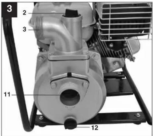
text_image
3 2 3 11 12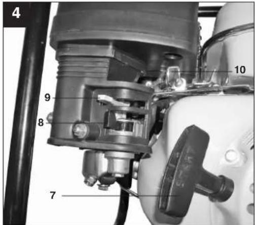
text_image
4 9 8 7 10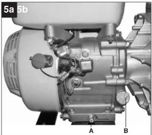
natural_image
Mechanical assembly diagram of a motor or engine component, labeled A and B (no text or symbols beyond labels)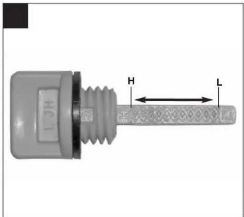
text_image
H L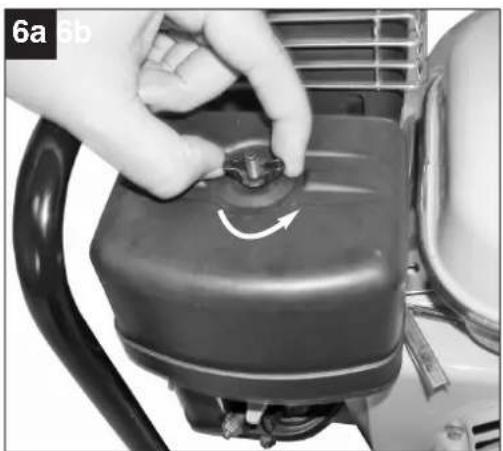
natural_image
Close-up of a hand adjusting a black mechanical component with a circular button, showing a curved arrow indicating rotation (no text or symbols visible)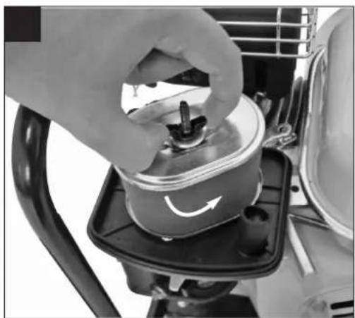
natural_image
Close-up of a hand pressing down on a cylindrical component with a curved arrow indicating rotation (no text or symbols visible)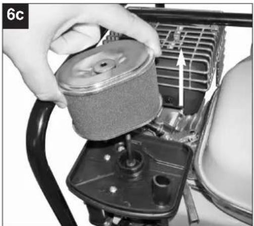
natural_image
Close-up of hands operating a mechanical component with a cylindrical component inserted, showing internal structure and a directional arrow (no text or symbols visible)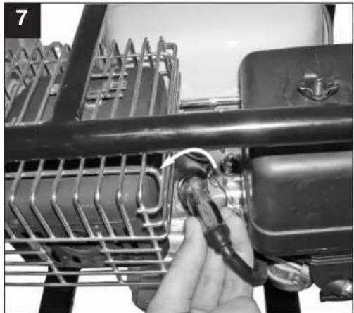
natural_image
Close-up of a hand adjusting a mechanical component with a cable, no visible text or symbolsGB
Table of contents
- Safety regulations
- Layout
- Intended use
- Technical data
- Before putting the equipment into operation
- Operation
- Cleaning, maintenance, storage and ordering of spare parts
- Disposal and recycling
- Troubleshooting guide
⚠️ Important!
When using equipment, a few safety precautions must be observed to avoid injuries and damage. Please read the complete operating manual with due care. Keep this manual in a safe place, so that the information is available at all times. If you give the equipment to any other person, give them these operating instructions as well.
We accept no liability for damage or accidents which arise due to non-observance of these instructions and the safety information.
1. Safety information
Please refer to the booklet included in delivery for the safety instructions.
CAUTION!
Read all safety regulations and instructions.
Any errors made in following the safety regulations and instructions may result in an electric shock, fire and/or serious injury.
Keep all safety regulations and instructions in a safe place for future use.
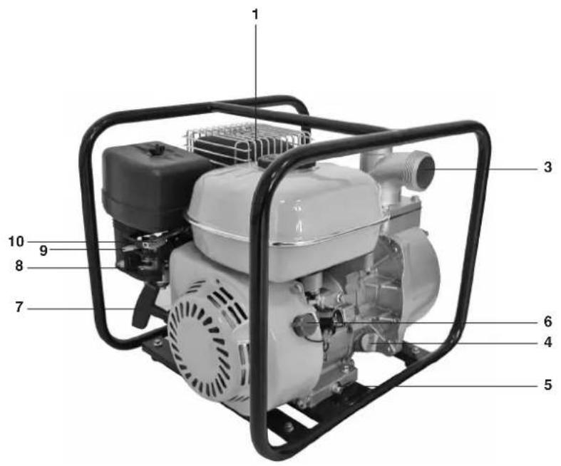
2. Layout (Fig. 1/4)
1 Tank cover
2 Refilling nozzle with screw
3 Pressure connection
4 Oil filler plug
5 Oil drain plug
6 ON/OFF switch
7 Reversing starter
8 Petrol cock
9 Choke lever
10 Throttle control
11 Suction connection
12 Water emptying plug
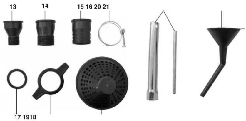
13 2x Threaded connector 1" external thread
14 2x Threaded connector 1.25" external thread
15 2x Hose connector 2"
16 3x Hose clip
17 2x Seal
18 2x Union nut
19 Intake cage
20 Spark plug wrench
21 Oil filler funnel
3. Proper use
The machine is suitable for irrigating and watering landscaped areas, vegetable beds and gardens and for operating lawn sprinklers.
The water can be taken from ponds, streams, rainwater butts, rainwater cisterns and springs if an initial filter is fitted.
The maximum temperature of the fluid must not exceed +35°C if the machine is operated permanently.
Clean water (sweet water), rainwater and low concentrations of washing lye can be used as the transport medium. The machine must not be used to transport inflammable, gassing, explosive and aggressive fluids (such as petrol, acids, lyes, silo percolating juice, etc.) and fluids that contain abrasive substances (such as sand).
The machine is to be used only for its prescribed purpose. Any other use is deemed to be a case of misuse. The user / operator and not the manufacturer will be liable for any damage or injuries of any kind caused as a result of this.
Please note that our equipment has not been designed for use in commercial, trade or industrial applications. Our warranty will be voided if the machine is used in commercial, trade or industrial businesses or for equivalent purposes.
GB
4. Technical data
Engine type: 4-stroke engine; air-cooled
Max. engine output: 4.8 kW / 6.5 bhp
Displacement: 196
Idle speed of engine: 1500 rpm
Maximum engine speed: 3600 rpm
Fuel: Regular unleaded petrol
Tank capacity: 3.6 l
Oil volume / type: 600 mL SAE#30
Spark plug: L7TC
Max. intake head: 6 m
Max. pumping rate: 35000 l/h
Max. delivery head: 26 m
Max. pressure: 2.6 bar
Weight (with empty tank): 28 kg
Intake/Discharge connector: 2" hose connection
2" / 1.25"/ 1" thread connector
L_WA sound power level: 95 dB
L_pA sound pressure level: 75 dB
5. Before starting
As a basic principle, we recommend the use of a preliminary filter and a suction set with suction hose, suction strainer and non-return valve, in order to prevent long priming periods and unnecessary damage to the pump as a result of stones and solid foreign bodies.
5.1 Preparing the machine
- Fill the engine with engine oil (see also point 7.2.1 Oil change).
- Fill the tank with petrol.
● Place the machine on a flat, firm surface.
5.2 Connecting and routing the intake and discharge lines
- Connect the intake line to the intake connection (Figure 3 / Item 11) and the discharge line to the discharge connection (Figure 3 / Item 3).
- Position the intake line so that it rises from the water withdrawal point to the pump. It is essential that you do not route the intake line above the height of the pump. Air bubbles in the intake line will slow down and prevent the intake process.
● Install the intake and discharge lines in such a way that they do not exert any mechanical pressure on the pump. - The intake valve should be low enough in the water to ensure that if the water level falls, the pump will not run dry.
● A leaking intake line will draw in air and therefore not draw in any water. - Do not draw in any foreign bodies (sand, etc.). If necessary install an initial filter.
6. Operation
The pump must be filled with the transport fluid at the filler neck (Figure 3 / Item 2) before the engine is started.
Note: We advise that you install a non-return valve in the intake line and fill it with water before you start the machine for the first time.
6.1 Starting the engine
- Set the On/Off switch (Figure 1 / Item 6) to "ON".
- Set the petrol cock (Figure 4 / Item 8) to the "ON" position.
- If the engine is cold, set the choke lever (Figure 4 / Item 9) to "Choke".
- Move the throttle lever (Figure 4 / Item 10) to the center position.
- Pull the starter cord (Figure 4 / Item 7) until the engine starts.
- When the engine has been running for approx. 30 seconds, move the choke lever to "Run".
If the engine is warm, leave the choke lever in the
"Run" position when starting.
Explanation of the positions of the throttle lever (Figure 4 / Item 10):
"Tortoise":
Engine in idling
"Hare":
Maximum delivery rate
6.2 Intake process
●During the priming process, the shut-off devices present in the pressure pipe (spray nozzles, valves etc.) must be completely open so that the air in the suction pipe can escape freely.
- Depending on the suction height and the air quantity in the suction pipe, the initial priming process can last for approx. 0.5 min. – 5 min. In the case of longer priming periods, top up again with water.
- If the pump is removed after use, it is essential that it is filled with water again the next time it is connected and started.
6.3 Stopping the engine
- Set the On/Off switch to "OFF".
- Close the petrol cock.
Running-in period:
For the first 20 hours of operation, the motor must not be operated at full throttle for too long.
Misfires, start-up difficulties:
Check whether
●fuel is flowing into the carburetor;
●the fuel filter is clean;
●the carburetor air valve is open;
●the air filter is clean;
●the spark plug is clean and the electrode gap is between 0.6 and 0.7mm.
7. Cleaning, maintenance, storage and ordering of spare parts
Disconnect the spark plug boot before doing any cleaning and maintenance work!
7.1 Cleaning
- Keep all safety devices, air vents and the motor housing free of dirt and dust as far as possible. Wipe the equipment with a clean cloth or blow it with compressed air at low pressure.
●We recommend that you clean the device immediately each time you have finished using it.
●Clean the equipment regularly with a moist cloth and some soft soap. Do not use cleaning agents or solvents; these could attack the plastic parts of the equipment. Ensure that no water can seep into the device.
7.2 Maintenance
In this connection, please also read the attached service information
7.2.1 Changing the oil
The engine oil is best changed when the engine is at working temperature
●Use only engine oil (10W40).
- Place the machine on a slightly inclined surface so that the oil drain plug is at the lower end (Figure 5a / Item A).
- Remove the oil filler screw (Figure 5a / Item B).
- Remove the oil drain plug and drain the warm engine oil into a suitable container.
●After all the oil has drained, screw in the oil drain plug and place the machine on a flat surface.
- Insert fresh engine oil up to the top mark on the oil dipstick (Figure 5b / Item H).
Important. Only inset the oil dipstick to check the oil level. Do not screw it in.
While the machine is working, the oil level must be between the two marks "L" and "H" (Figure 5b).
Dispose of the waste oil properly.
7.2.2 Air filter
Clean the air filter at regular intervals, and replace it if necessary.
- Remove the screw from the air filter cover (Figure 6a)
- Remove the air filter cover.
- Remove the screw from the air filter element (Figure 6b)
- Remove the air filter element (Figure 6c).
- Clean the air filter by tapping it, blowing it out with compressed air or by washing it with soap suds. Important. Leave the air filter to dry before you refit it.
●Assemble in reverse order.
7.2.3 Spark plug
Clean the spark plug at regular intervals, and replace it if necessary. Set the electrode gap to 0.6 mm.
- Remove the spark plug boot by twisting it (Figure 7)
- Remove the spark plug using a spark plug wrench
●Clean the spark plug with a copper wire brush or fit a new one.
●Assemble in reverse order.
GB
7.3 Storage
● Rinse the pump thoroughly with water before lengthy periods of inactivity or winter storage.
- Close the petrol cock and allow the engine to run until it stops to empty the carburetor.
- Fill the tank fully to prevent rust formation.
- Remove the drain plug (Figure 3 / Item 12) and fully drain the pump housing.
- Store the machine in a dry place out of the reach of children.
7.4 Ordering replacement parts
Please quote the following data when ordering replacement parts:
- Type of machine
• Article number of the machine
• Identification number of the machine
● Replacement part number of the part required
For our latest prices and information please call 1300 922 271
8. Disposal and recycling
The unit is supplied in packaging to prevent its being damaged in transit. This packaging is raw material and can therefore be reused or can be returned to the raw material system.
The unit and its accessories are made of various types of material, such as metal and plastic.
Defective components must be disposed of as special waste. Ask your dealer or your local council.
9. Troubleshooting
| Fault Cause Remedy | ||
| Engine does not start Spark plug fouled | Air filter dirtyNo fuel in the tankAutomatic oil cut-out has not responded | Clean or replace the spark plugClean the air filter.Top up fuel.Check oil level, top up engine oil |
| Pump fails to prime Intake valve not in the waterNo water in the pump chamberAir in the intake lineIntake cage (intake valve) blockedMax. intake head exceeded | Place the intake valve in the waterFill the pump chamber with water through the filler neckCheck the intake line for leaks and seal it if necessary.Clean intake cageCheck intake head and reduce it if necessary | |
| Insufficient pumping rate Intake head too highIntake cage soiledWater level falling rapidly and in-take line is out of the water-Pump performance reduced by deposits | Check intake head and reduce it if necessaryClean intake cagePlace the intake line at a deeper levelClean pump | |
Important. The pump must not run dry.
The guarantee provided in this Guarantee Certificate is given by Einhell Australia Pty Limited ACN 134 632 858 of 6/166 Wellington Street, Collingwood, Victoria (Telephone number 1300 922 271) (Einhell Express Guarantee).
GB GUARANTEE CERTIFICATE
Dear Customer,
All of our products undergo strict quality checks. In the unlikely event that your device develops a fault, please contact our service department at the address shown on this guarantee certificate. Of course, if you would prefer to call us then we are also happy to offer our assistance under the service number printed below. Please note the following terms under which claims under the Einhell Express Guarantee can be made:
- The benefits conferred by the Einhell Express Guarantee are in addition to all rights and remedies which you may be entitled to under the Australian Consumer Law, and any other statutory rights you may have under other applicable laws. This Einhell Express Guarantee does not exclude, restrict or modify any such rights or remedies.
We do not charge you for the Einhell Express Guarantee. - Our goods come with guarantees that cannot be excluded under the Australian Consumer Law. You are entitled to a replacement or refund for a major failure and for compensation for any other reasonably foreseeable loss or damage. You are also entitled to have the goods repaired or replaced if the goods fail to be of acceptable quality and the failure does not amount to a major failure.
- The Einhell Express Guarantee only covers problems caused by material or manufacturing defects, and our liability under the Einhell Express Guarantee is limited, at our discretion, to the rectification of these defects or replacement of the product. Please note that the product has not been designed for use in commercial, trade or industrial applications. Consequently, the Einhell Express Guarantee will not apply if the product is used in commercial, trade or industrial applications or for other equivalent activities.
- The following are also excluded from the Einhell Express Guarantee: compensation for transport damage, damage caused by failure to comply with the installation/assembly instructions or damage caused by unprofessional installation, failure to comply with the operating instructions (e.g. connection to the wrong mains voltage or current type), misuse or inappropriate use (such as overloading of the product or use of non-approved tools or accessories), failure to comply with the maintenance and safety regulations, ingress of foreign bodies into the product (e.g. sand, stones or dust), effects of force or external influences (e.g. damage caused by the product being dropped) and normal wear resulting from proper operation of the product. The Einhell Express Guarantee will also not apply if any attempt is made to tamper with the product.
- The Einhell Express Guarantee is valid for a period of 2 years starting from the purchase date of the product. Claims made under the Einhell Express Guarantee should be submitted before the end of this guarantee period and within two weeks of the defect being noticed. No claims under the Einhell Express Guarantee will be accepted if submitted after the end of this guarantee period. The original guarantee period remains applicable to the device even if repairs are carried out or parts are replaced. In such cases, the work performed or parts fitted will not result in an extension of the guarantee period for the Einhell Express Guarantee, and the Einhell Express Guarantee will not apply for the work performed or parts fitted. This also applies when an on-site service is used.
- To make a claim under the Einhell Express Guarantee, please send the relevant product postage-free to the address shown below and enclose either the original or a copy of your sales receipt or another dated proof of purchase. It would help us if you could describe the nature of the problem in as much detail as possible. If the defect is covered by the Einhell Express Guarantee, your product will be repaired immediately and returned to you, or we will send you a new device (at our election).
Any costs incurred by you in making a claim under this Einhell Express Guarantee, unless specified otherwise in this guarantee certificate, must be borne by you.
Of course, we are also happy to offer a chargeable repair service for any defects which are not covered by the scope of the Einhell Express Guarantee or for products which are no longer covered by the Einhell Express Guarantee. To take advantage of this service, please send the product to our service address.
EINHELL AUSTRALIA PTY LTD
6/166 Wellington Street
Collingwood VIC 3066
Australia
Phone: 1300 922 271
EH 07/2013 (01)