
XEV1K11T2 - Switch HAGER - Free user manual and instructions
Find the device manual for free XEV1K11T2 HAGER in PDF.
| Brand | Hager |
| Model | XEV1K11T2 |
| Product type | Electric vehicle charging station |
| Maximum power | 11 kW (three-phase) / 7 kW (single-phase) |
| Maximum current | 32 A (single-phase and three-phase) |
| Supply voltage | 230 V~ (single-phase) / 400 V~ (three-phase) |
| Frequency | 50/60 Hz |
| Connector type | Mode 3 – T2/T2S |
| Protection rating | IP55 / IK10 |
| Weight | 6,2 kg |
| Dimensions (H x L x P) | 549 x 250,5 x 173 mm |
| Operating temperature | -25°C to +50°C |
| Relative humidity | 5% to 95% |
| Maximum altitude | 2000 m |
| Pollution degree | 3 |
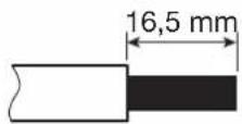
| Minimum cable cross-section | 10 mm² (copper) |
| Standby consumption | 1,7 W |
| Features | Key access control, USB diagnostics, TIC, charging modes immediate/deferred exclusive/inclusive, 6 mA DC current detection |
| Safety | 40 A circuit breaker, contactor, optional shunt trip, welded contact detection |
| Maintenance | Annual tightening check, electrical maintenance by a professional |
| Installation | By a qualified electrician, wall or pedestal mounting |
| Warranty | Manufacturer's warranty (refer to general terms and conditions) |
Frequently Asked Questions - XEV1K11T2 HAGER
User questions about XEV1K11T2 HAGER
0 question about this device. Answer the ones you know or ask your own.
Ask a new question about this device
Download the instructions for your Switch in PDF format for free! Find your manual XEV1K11T2 - HAGER and take your electronic device back in hand. On this page are published all the documents necessary for the use of your device. XEV1K11T2 by HAGER.
USER MANUAL XEV1K11T2 HAGER
EN installation manual - p. 30
Witty charging station for electric vehicle
natural_image
Line drawing of a mechanical device with a labeled component 'shager' (no other text or symbols)natural_image
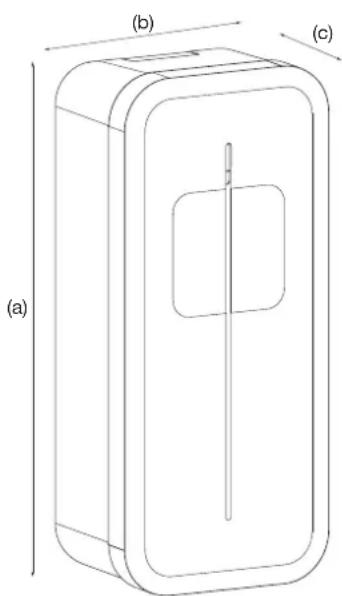
Technical line drawing of a rectangular device with internal components, labeled (a), (b), and (c) for scale (no text or symbols on the diagram itself)| a (mm) 549 |
| b (mm) 250,5 |
| c (mm) 173 |

natural_image
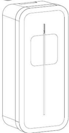
Line drawing of a rectangular box with a central square and vertical line (no text or symbols)
natural_image
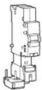
Technical line drawing of a mechanical component with internal circular features and mounting brackets (no text or symbols)Carte TIC/CHP (selon version)
natural_image
Technical line drawing of a mechanical device mounted on a vertical support frame (no text or symbols)5. Installation
5.1. Ouverture


natural_image
Technical line drawing of a mechanical device with an open lid and internal compartments, showing no text or symbols.2
natural_image
Technical line drawing of a battery pack assembly showing internal components and mounting points (no text or symbols)3
natural_image
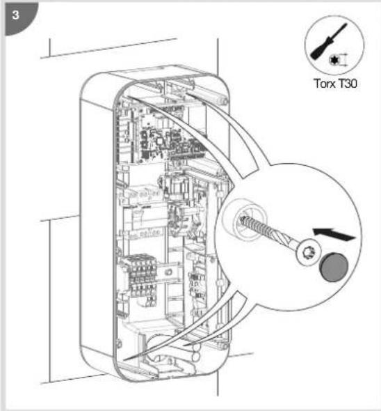
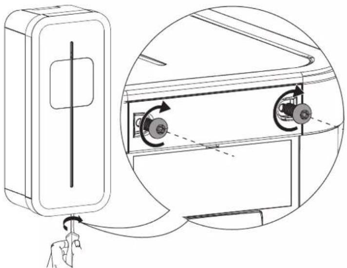
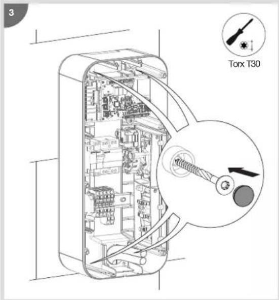
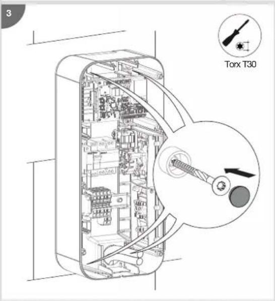
Technical line drawing of a mechanical housing component with an inset showing a gear mechanism (no text or symbols)5.2. Fixation


natural_image
Technical illustration of a door panel and its internal circuit switch (no text or symbols)
natural_image
Technical line drawing of an internal electrical enclosure with internal components and a magnified inset showing internal wiring (no text or symbols)9. Câblage de la charge diff érée
natural_image
Diagram of a computer interface showing an inserted port with a magnified inset highlighting the internal structure (no text or symbols present)3

i
natural_image
Diagram of a mechanical component with a downward arrow indicating a force or movement (no text or symbols present)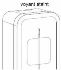
natural_image
Diagram showing a computer interface with an inset close-up of a device component (no text or symbols visible)6

7. Modifier la configuration
natural_image
Line drawing of a laptop with an inset showing a battery being inserted into it (no text or symbols present)4
natural_image
Diagram of a computer interface showing an open circuit board with a close-up inset of the device (no text or symbols visible)5
6
natural_image
Diagram of an electronic device showing internal components and a magnified view of the battery module (no text or symbols present)8
natural_image
Cross-sectional diagram of a device showing internal components and a magnified view of a mechanical component (no text or symbols)2

natural_image
Technical diagram of a mechanical device interior showing internal components and a magnified view of the internal structure (no text or labels)3

natural_image
Technical diagram of an internal electronic device showing internal components and a magnified view of the device's internal structure (no text or labels present)4
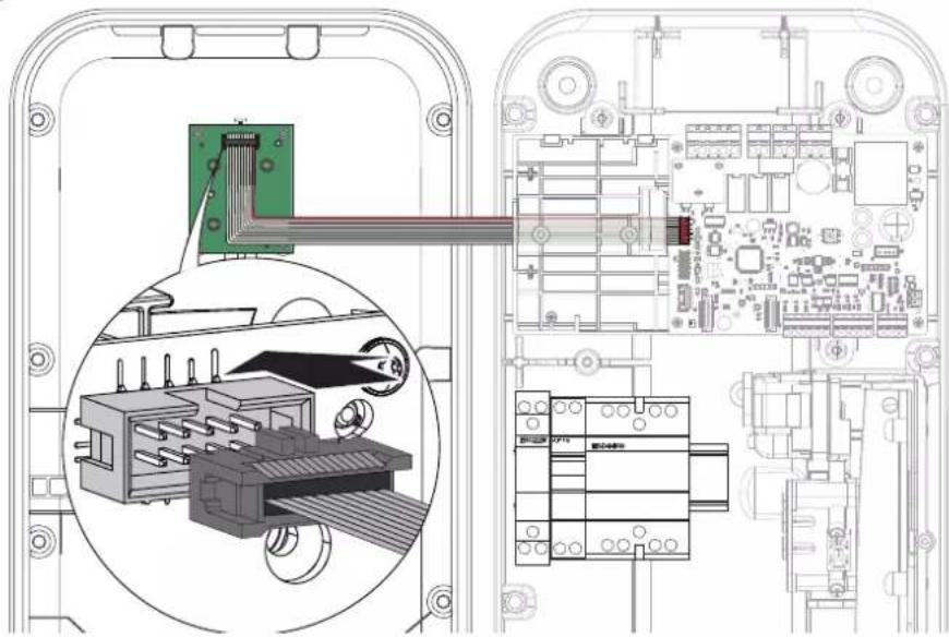
Câbler la nappe IHM
natural_image
Technical diagram of an electronic device showing internal components and a close-up view of the circuit board (no text or symbols present)6


natural_image
Hand inserting a fuse into an electrical switch (no text or symbols visible)natural_image
Top-down schematic of an electronic circuit board layout with components like capacitors, resistors, and connectors (no text or labels)2 possibilités :
natural_image
Technical diagram of a mechanical component with internal flow arrows (no text or symbols)3
natural_image
Diagram showing a device with a hand operating it, connected to a close-up of its internal components (no text or symbols present)
4
- Choisir le bon autocollant.


natural_image
Diagram of a device with a cable connector and a 3D model, showing no text or symbols.2
3
natural_image
Diagram showing a car door panel connected to a connector via cable, with no visible text or symbols14.2. Forcer la charge
1
natural_image
Diagram of a device with a cable being inserted into a housing (no text or symbols visible)2
natural_image
Technical line drawing of a device with a cable and connector (no text or symbols)2
3
natural_image
Diagram of a device with an attached plug, showing internal components and a directional arrow (no text or symbols)15. Diagnostic de la borne de charge
15.1. Introduction
| [Informations] | |
| Version = 7.0.1.0 | |
| Hardware = B1280 | |
| D/N_Timer = 0 s | |
| Blackout_timer = 0 s | |
| Wifi = absent | |
| [Inputs] | |
| Slider = Delayed inclusive | |
| Current_selector = 32 A | |
| Tariff = | High tariff |
| CHP_Input = | Open (unused) |
| Temp = | 27 °C |
| Key_Switch = | Unlocked |
| Installation_phases = | Triple-phase |
| [TIC] | |
| Activity = Active | |
| Data = Valid (24587) | |
| Mode = Historique | |
| Isousc = 45 A | |
| linst = 1 A | |
| Tariff = HP.. (High tariff) | |
| [1] | |
| Socket = 1 | |
| T_connect 16428 | s |
| T_charge = 11602 | s |
| Energy = 35680 | |
| [Maintenance] | |
| Ch_duration_1 = 625 h | |
| Cycles_1 = 179 | |
| Ch_duration_2 = | 1 h |
| Cycles_2 = | 5 |


natural_image
Technical line drawing of a mechanical assembly with no visible text or symbolsService Assistance Technique
- Please read before carrying out any electrical wiring on the charging station 31
1.1. Wiring the shunt coil (Shunt Trip function) 31
-
Overview of the standard range.... 31
-
Description of the exterior 32
-
Description of the interior 33
-
Installation 34
5.1. Opening 35
5.2. Mounting....35
-
Electrical protections for charging stations 36
-
Power cabling 37
-
Wiring the shunt coil MZ203 (Shunt Trip function) 37
-
Wiring deferred charging 38
-
Charging station configuration.... 39
10.1. Charging station configuration procedure 39
10.2. Maximum power setting 39
10.3. Modify the settings using a USB flash drive.... 40
-
Finalisation 44
-
Contactor and shunt trip function test 45
-
Closing the charging station.... 46
-
Charging station operation 47
14.1. Selecting the charging mode.... 47
14.2. Forcing the charge 48
14.3. Unlocking the charging cable.... 48
- Charging station diagnostic.... 49
15.1. Introduction 49
15.2. Diagnostic parameters and their explanations 49
15.3. Log file 52
- Indicators....53
16.1. Normal operation....53
16.2. Anomalies 53
-
Internal wiring of the charging stations 54
-
Electrical maintenance 55
-
Technical characteristics.... 56
-
Lexicon....57


All of the FAQs, resources and contacts you need to install a Witty charging stations are available by scanning the Flashcode or by going to: http://hgr.io/r/XEV1K11T2 and http://hgr.io/r/XEV1K22T2

Safety advice
- Electrical appliances should only be installed and mounted by a qualified electrician. Accident prevention measures in force in the country must be respected. Failure to adhere to the installation instructions could lead to damage to the appliance, a fire or could be a danger to others.
- Please observe the measures and standards in force for SELV electrical circuits when installing and fitting the cables. Before any intervention on the appliance or the charge, switch off the charging station at the circuit breaker upstream and lockout the appliance if necessary. After opening the charging station, check that there is no voltage running to any of the parts.
- When installing the charging station, check that there are no environmental conditions (rain, mist, snow, dust, wind, etc.) that could pose a danger or cause a breakage during handling and when powering on again.
- Remember to take into account all of the circuit breakers delivering potentially dangerous voltages to the appliance or charge.
- Risk of electrical shock.
- Please separate the wiring between the high current/low voltage (D/N input, output to shunt coil) of the controller board and the low current/extra low voltage (TIC input, CHP inputs/outputs) of the TIC board.
1. Please read before carrying out any electrical wiring on the charging station
1.1. Wiring the shunt coil (Shunt Trip function)
The electrical wiring of the shunt coil of this new charging station has been modified.

To prevent any malfunctions in the charging station, please refer to chapter 7. Wiring the shunt coil MZ203 (Shunt Trip function).
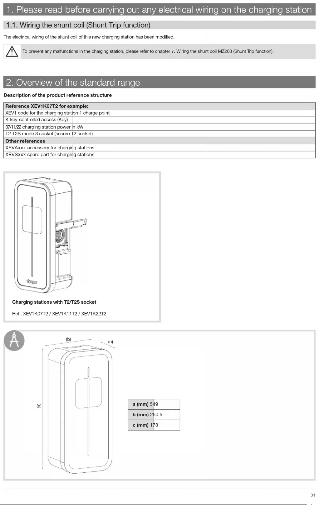
2. Overview of the standard range
Description of the product reference structure
| Reference XEV1K07T2 for example: | |
| XEV1 code for the charging station | on 1 charge point |
| K key-controlled access (Key) | |
| 07/11/22 charging station power in kW | |
| T2 T2S mode 3 socket (secure T2 socket) | |
| Other references | |
| XEVAxxx accessory for charging stations | |
| XEVSxxx spare part for charging stations | |

natural_image
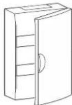
Line drawing of a device casing with a door and internal components, labeled 'shaper' at the bottom (no other text or symbols)Charging stations with T2/T2S socket
Ref.: XEV1K07T2 / XEV1K11T2 / XEV1K22T2

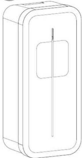
natural_image
Technical line drawing of a rectangular device with internal components, labeled (a), (b), and (c) for dimension reference (no text or symbols on the diagram itself)| a (mm) 549 |
| b (mm) 250.5 |
| c (mm) 173 |

natural_image
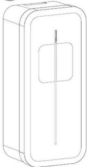
Line drawing of a rectangular box with a central slot and a rectangular cutout (no text or symbols)2 locking keys to secure access to the charging station and located inside the charging station.

Identification label


Optional

Ref.: XEVA100 Refer to the instructions provided with the cable support to install it.


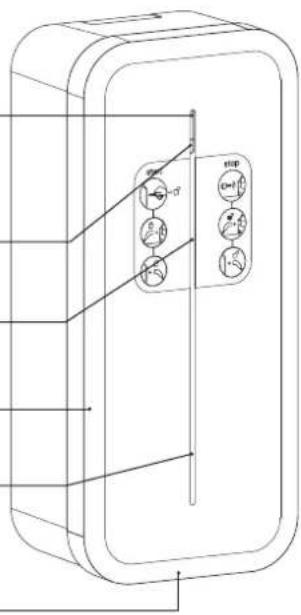
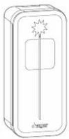
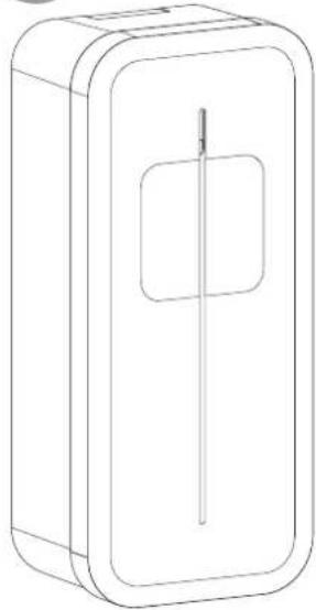
3. Description of the exterior
- Exterior
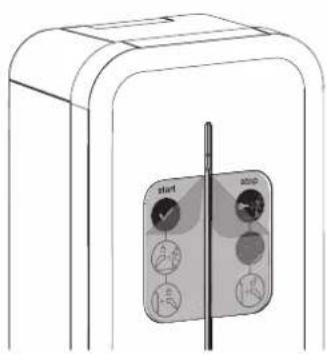
Lighting strip
Hover button
Location of user sticker
Frame
Location for cable support
Cover opening


natural_image
Technical line drawing of a door panel with internal components (no text or symbols)Mode 3 socket
T2/T2S
Charging station lock
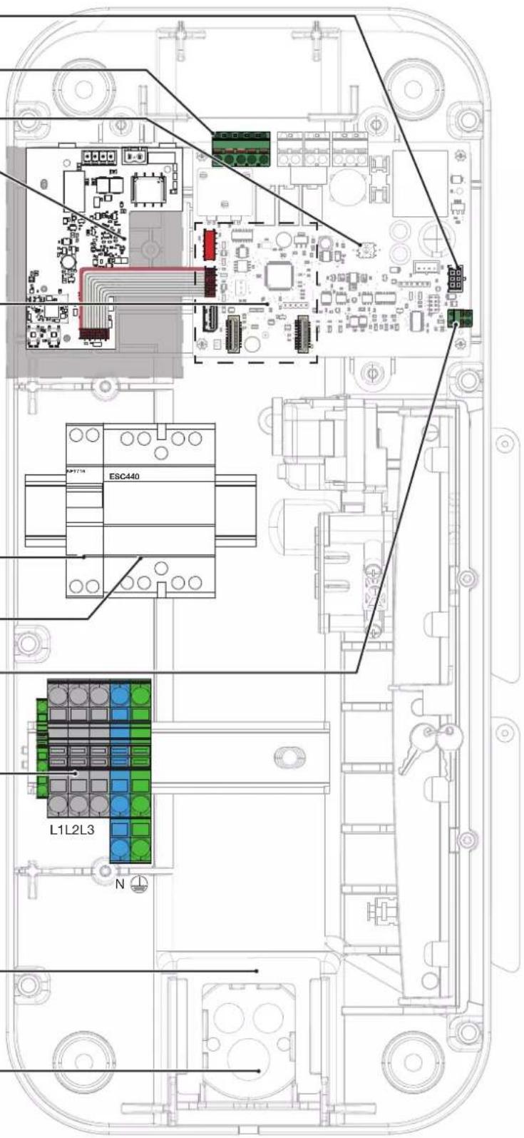
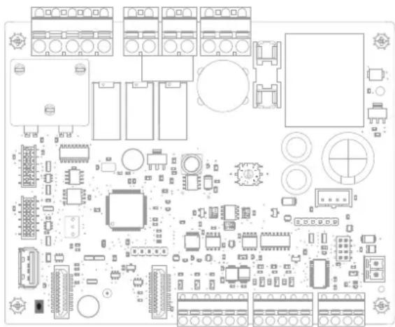
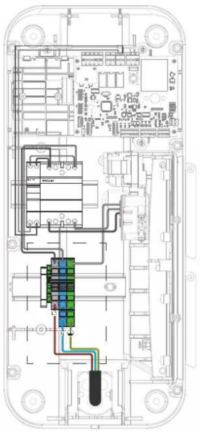
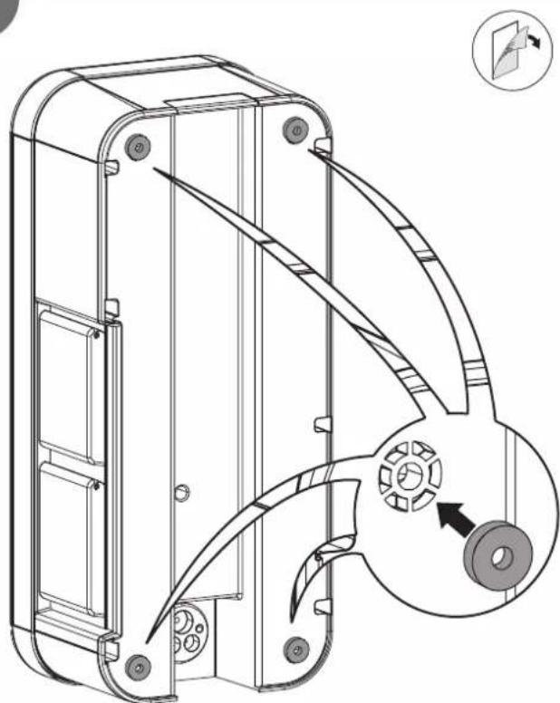
4. Description of the interior
• Electrical composition of the base
6 mA detection connectors
Day/night input
and Shunt Trip (D/N) and
(ST) terminal block
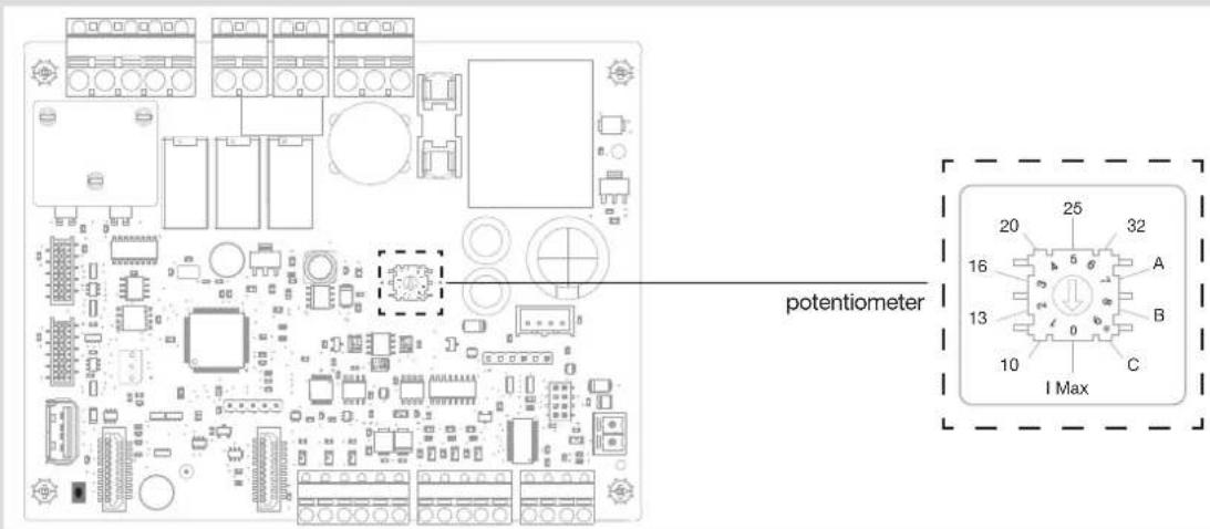
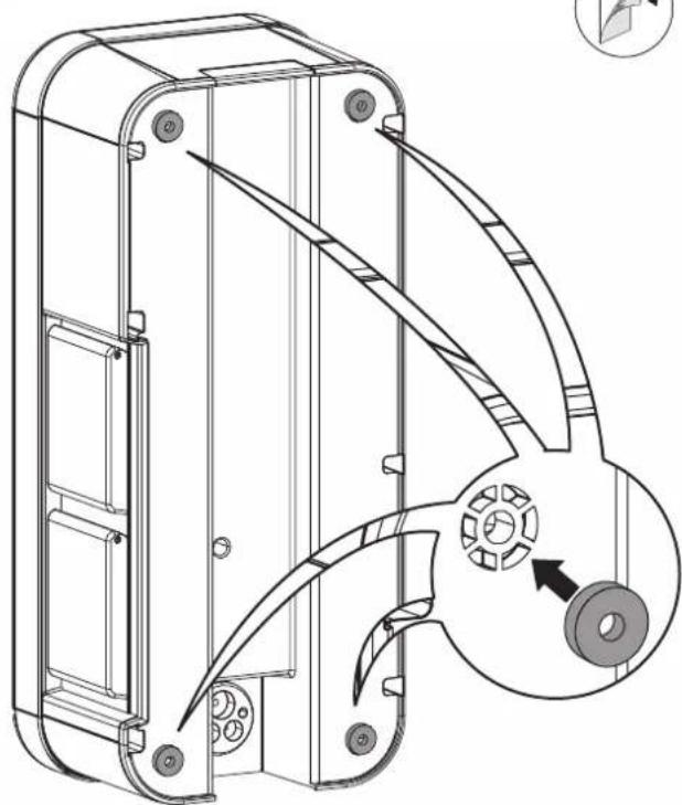
Coding wheel for the definition of the maximum power
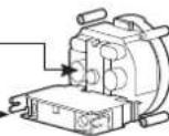
TIC/CHP
board
(optional)
HMI
connector (LED)
Connector for
TIC board
USB port
Location of
WIFI module or Ethernet
16 A protective circuit breaker, controller board
40 A contactor, T2/T2S socket
Pulse counting input connector
Three-phase and earth connecting terminal block or
Single-phase and earth connecting terminal block
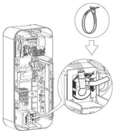
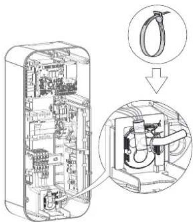
Cable retaining piece and cable tie
Cable duct
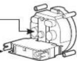
• Electrical composition of the front panel
HMI electronic signalling card (XEVS020)

natural_image
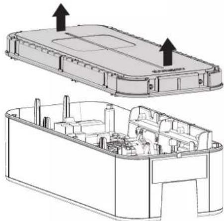
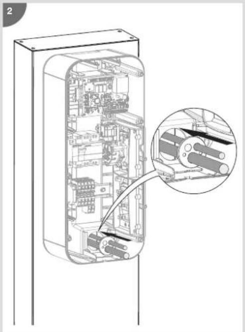
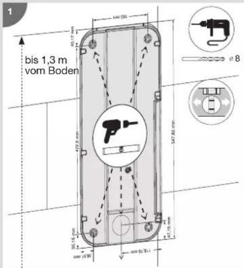
Technical line drawing of a mechanical device mounted on a vertical support frame (no text or symbols)5. Installation
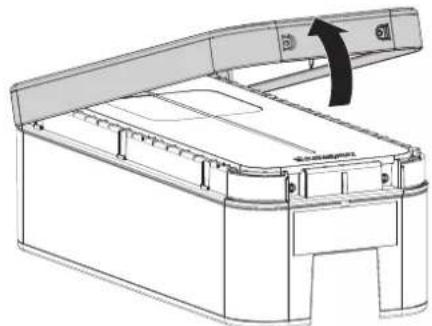
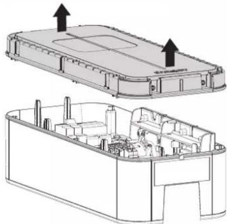
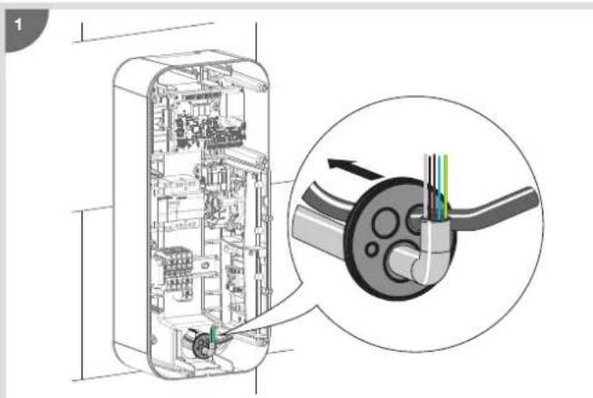
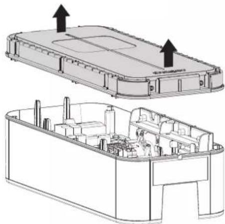
5.1. Opening

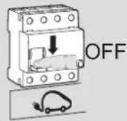
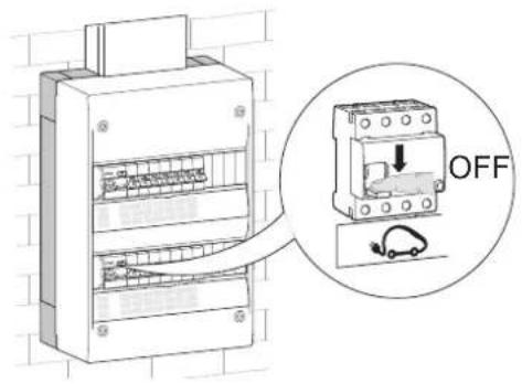
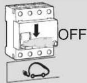
The charging station must be switched off before opening.

When leaving the factory, the frame and the front panel are not screwed on, and the cable of the front LED electronic board is not connected.
1
natural_image
Technical line drawing of a mechanical device with an open lid and internal compartments, showing no text or symbols.2
natural_image
Technical line drawing of an electronic device casing with internal components and mounting points (no text or symbols)3
natural_image
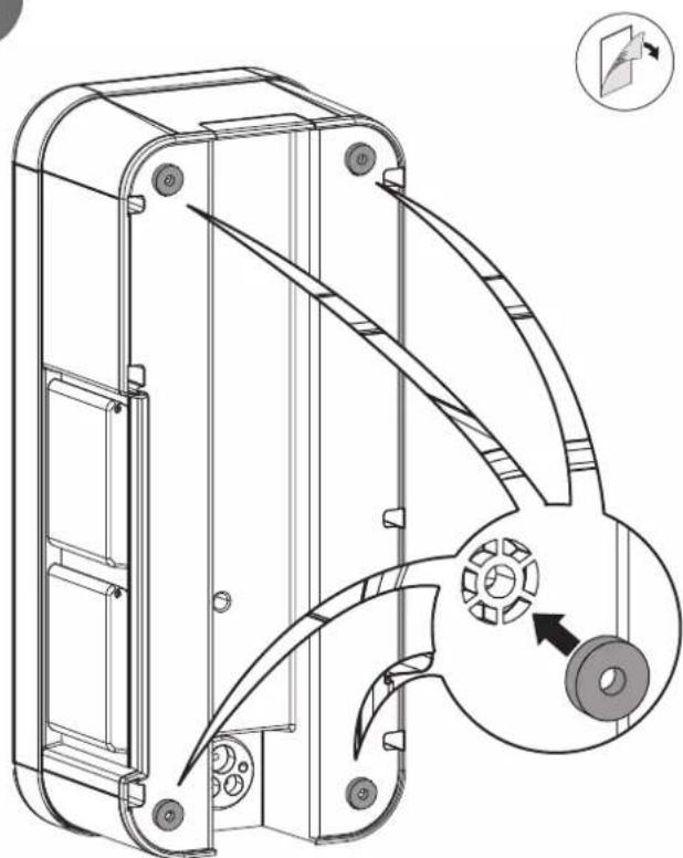
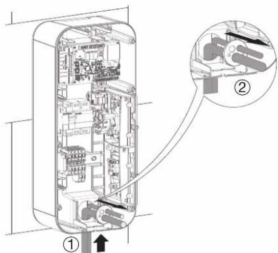
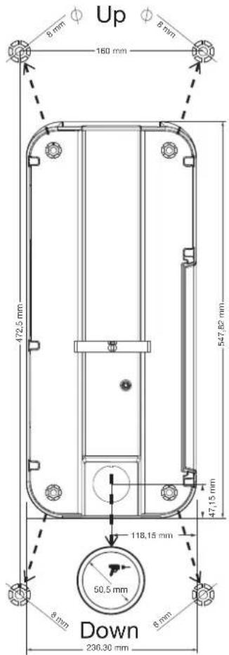
Technical line drawing of a mechanical housing component with an inset showing a close-up view of a gear mechanism (no text or symbols present)5.2. Mounting

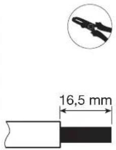
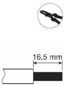
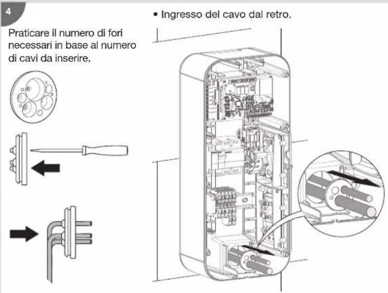
Before mounting the charging station, please ensure that all of the cables are present:
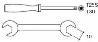
- 3 Ph + N + Earth for a three-phase charging station, wire diameter: 5G10 or 5G16 flexible or rigid or 1Ph + N + Earth for a single-phase charging station, wire diameter: 3G10 or 3G16 flexible or rigid,
- an SYT2 remote reading cable, or failing that, a cable with 1 twisted pair (wired connection) with a TIC board,
- a 2-wire cable (2 x 1.5 mm ^2 ) for the "Shunt Trip" function and/or the Day/Night (D/N) function (optional),
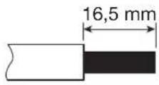
- the minimum wire diameter for a charging station with a current rated at 32 A is 10 mm ^2 .

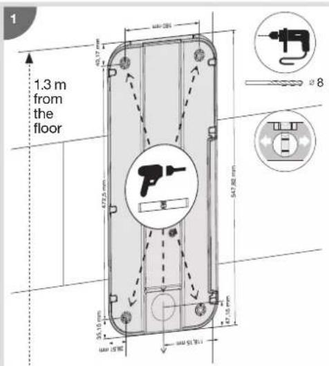
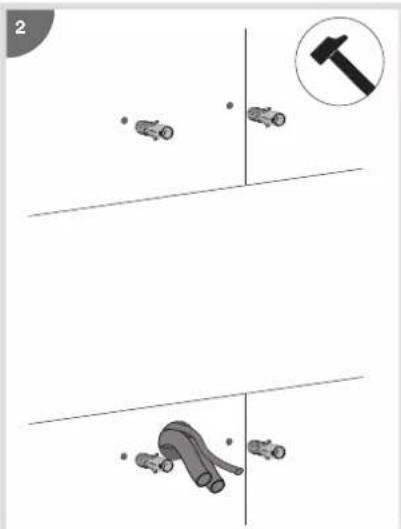

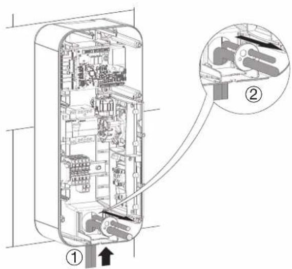
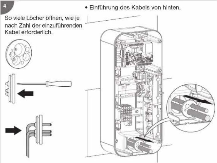
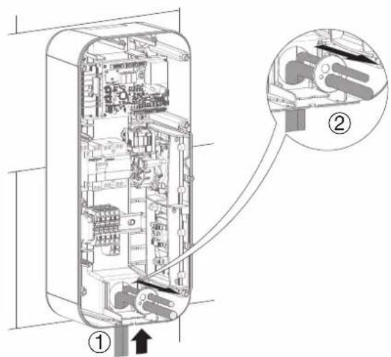
- Cable inlet at the top. • Cable inlet at the bottom.


Refer to the instructions supplied with the stand to install the XEVA110 (for 1 charging station) or XEVA115 (for 2 charging stations) base and stand. Then follow the steps below.

natural_image
Diagram showing a door panel with 'sheager' label and a separate electrical box with three buttons (no text or symbols on the main components)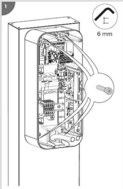
natural_image
Technical line drawing of an internal mechanical or electronic device casing with a magnified inset showing internal components (no text or symbols)6. Electrical protections for charging stations
• Quality of the earthing according to the EV READY label 1.4
NOK

OK TN or TT neutral system
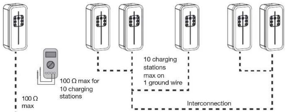
flowchart
graph TD
    A["100 Ω max"] --> B["100 Ω max for 10 charging stations"]
    B --> C["10 charging stations max on 1 ground wire"]
    C --> D["Interconnection"]
- Detection of contacts stuck to the contactor according to the EV READY 1.4 label.
All of the charging stations with a rated load power greater than 3.6 kW are provided with a device that detects if a contact is stuck to the contactor.
Shunt coils MZ203
EV READY 1.4
Electrical network disconnection if the contactor is stuck


According to standard EN 61851-1, this charging station incorporates a DC-CDC conforming to IEC 62955. In the event of detection of a DC component > 6 mA at the level of the fault current, this DC-CDC acts on the power contactor also integrated into the terminal, which automatically cuts power from the charging station. This 6 mADC detection device eliminates the need for a type B differential. All of the circuits must be installed completely in the same structure (from the electrical point of view) of the building.
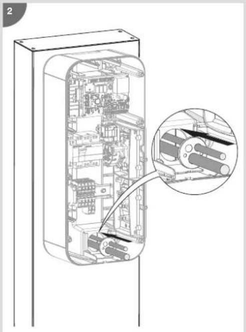
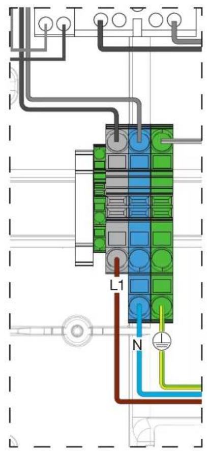
7. Power cabling
- Single-phase charging station power cabling: 1 Ph + N + E

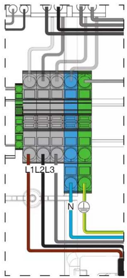
- Three-phase charging station power cabling: 3 Ph + N + E

8. Wiring the shunt coil MZ203 (Shunt Trip function)
The shunt coil - 230/415 V AC - HAGER MZ203 is an additional, non-compulsory safety mechanism that complements the mandatory differential switch + circuit breaker pairing, in order to ensure the complete electrical protection of your charging station. It is implemented to cut the power to the charging station in the event that the contactor of the T2/T2S socket becomes stuck.
The shunt coil must be present in order to obtain ZE Ready certification.
It couples to the circuit breaker, enabling it to be tripped remotely.

9. Wiring deferred charging
Use the 230V input to shed or authorize the load (with a digital time switches for example):

10. Charging station configuration

No vehicle must be connected when the charging station is switched on.

If the key lock has been activated in the charging station configuration, then for any action on the station such as configuration, vehicle charging, mode change, forcing the charge, charge release or switching to hotspot mode, the station must be in the unlocked position (key in the ON position).
10.1. Charging station configuration procedure
On leaving the factory, the charging station is pre-configured to operate with its configuration. An example configuration with a detailed description is provided in step 7 "Edit configuration".
To modify certain charging station operating parameters, according to the electrical installation and/or your customer requirements, a blank USB flash drive must be used for each new installation use a 1 to 4 GB USB flash drive in FAT32 format.
If, however, the factory settings comply with the customer's end use, please go directly to chapter 13. Charging station closure.
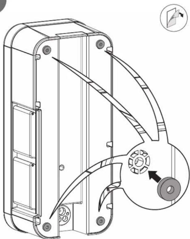
10.2. Maximum power setting
The maximum power of the charging station can be set via the encoder wheel on the electronic card.
The different ratings are 10 A, 13 A, 16 A, 20 A, 25 A, 32 A.
In factory "down arrow" position, the power taken into account is that of the configuration file.
- Configuration for compliance with EV Ready 1.4:
For compliance with EV Ready 1.4, the "Charging station current" parameter can only take values whose cells are marked with a tick in the table below.
| Charging station on | ||
| single-phase net-work | three-phase network | |
| 10 A | ||
| 13 A | √ | √ |
| 16 A | √ | √ |
| 20 A | √ | √ |
| 25 A | √ | √ |
| 32 A | √ | √ |
- Configuration for compliance with ZE Ready 1.4:
For compliance with ZE Ready 1.4, the "Charging station current" parameter can only take values whose cells are marked with a tick in the table below.
| Charging station on | ||
| single-phase net-work | three-phase network | |
| 10 A | ||
| 13 A | ||
| 16 A | √ | |
| 20 A | √ | √ |
| 25 A | √ | √ |
| 32 A | √ | √ |
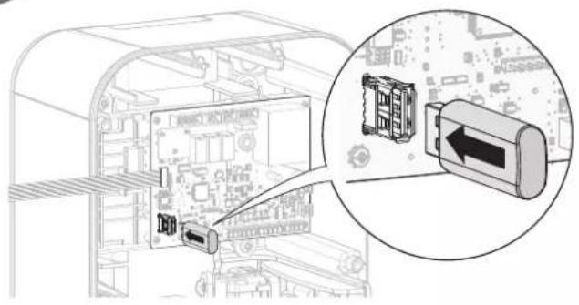
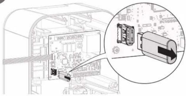
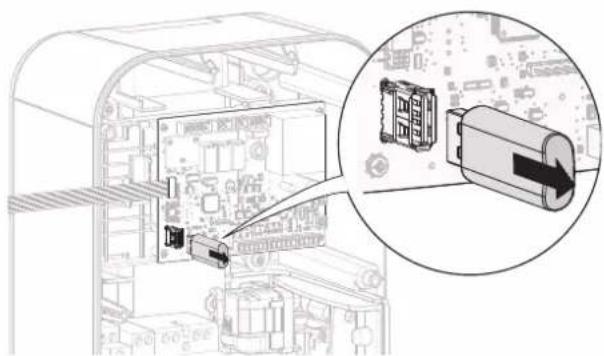
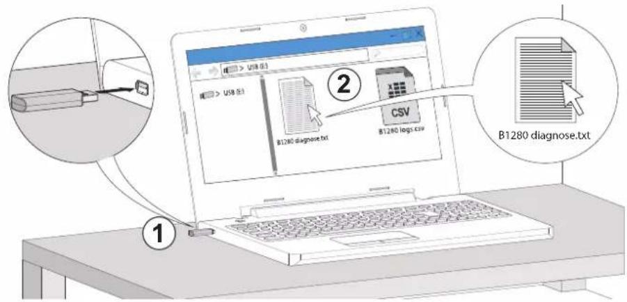
10.3. Modify the settings using a USB flash drive
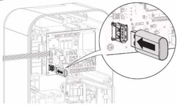
1
2
natural_image
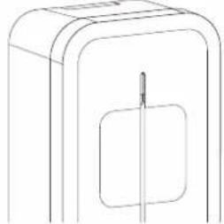
Diagram showing a computer interface with an inserted cable and a close-up of the cable connector (no text or symbols visible)3
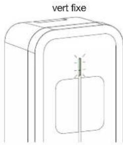
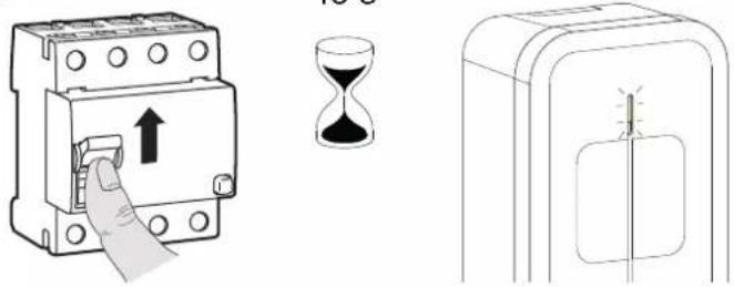
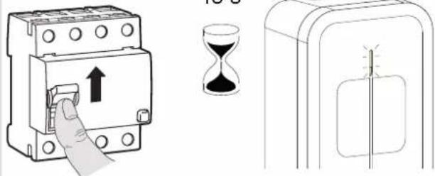
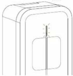
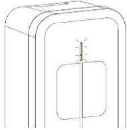
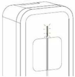
steady green

natural_image
Simple line drawing of a device with a vertical line and a small light bulb on the side panel (no text or symbols)i
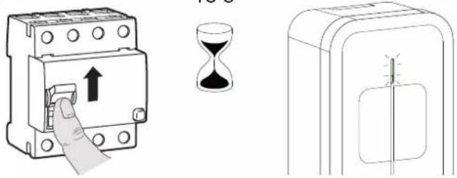
- If the charging station is equipped with a TIC board, please wait 60 seconds for all of the parameters of the electric meter to be taken into account.
- After a few seconds, the green LED on the controller board lights up, flashes twice and then stays on. The "B1280 diagnose.txt" configuration file was copied to the flash drive as well as a "B1280 logs.csv" log file, which traces all the events that have taken place on the charging station. This file is empty at the first charge.
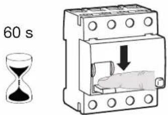
4

natural_image
Diagram of a mechanical component with a downward arrow indicating a force or movement (no text or symbols present)indicator light off

natural_image
Simple line drawing of a rectangular box with a square cutout and a vertical line inside (no text or symbols)5
natural_image
Diagram showing a computer interface with an inset close-up of a battery module (no text or symbols visible)6

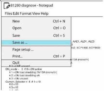
7. Modifying the configuration
The text file B1280 diagnose.txt, which was generated on the USB flash drive, is used to configure certain functions of the charging station.
The first column contains the names of the parameters; this column must not be modified.
The second column corresponds to the current value of the parameter; it can be modified. The one below is an example of an XEV1K07T2
charging station.
The third column indicates the values authorised on the relevant parameter.
Example: I want the lock to be enabled in order to limit access to the charging station.
To do this, replace 0 with 3 in the current value column.

31280 diagnose - Bloc - notes
| Parameters | Current values | Authorised values Comments | |
| [Conf i g] Access control = | 0 # 0-> | Stand Alone-Home# 3->Key-Switch | This fi eld takes the value 0 if the customer does not want to use the key. The charging station will always remain accessible for vehicle charging. It takes the value 3 if the customer wants to use the key. In this case, the charging station must be unlocked (put the key in the ON position) to charge the vehicle.Once charging has started, the key can be turned to OFF and removed. The charge will fi nish but a new charge will not be allowed. |
| [Manager] Name = " | “ # Charge | Point Name You can give a name to the charging station | betweenthe quotes, for example: the name of the customer.Example: "René Dupond". The diagnose fi le generated will be "B1280 René Dupond.txt" and the log "B1280 logs René Dupond.csv". |
| Wh_per_impulse = 0 | # 0->No Counter | # 1-> ECP140D, ECR140D, SAIA BURGESS AAD1,AAE1, ALD1, ALE3# 5->ECP380D, ECR380D# 10->SAIA BURGESS AAE3# 100->HAGER EC051, EC352 | This parameter takes the value 0 if no meter is used in the charging station. It takes the value 1 for the ECP140D meter and the value 5 for the ECP380D meter.Refer to the B1280 diagnose .txt fi le when using other meters. |
| Phase_number = 1 # | 1->single phase | # 3->three phase | This parameter is set by default according to the type of charging station: to the value 1 in the case of a single-phase station and to 3 in the case of a three-phase station. A three-phase charging station can be connected to a single-phase electrical network. In this case, this parameter must be set to 1 and it is imperative to connect the phase/neutral power supply to phase 1 of the three-phase charging station. |
| CHP_mode = 3 # 0-> | >CHP active | # 1->CHP load shedding 7A/13A (mono/tri)# 2->CHP load shedding 0A# 3->CHP unused | This parameter should be set when the CHP* function is required, i.e. with a cogeneration system.When this parameter is set to 0 and the CHP input is active, it signals to the controller that energy is supplied by an alternative way (cogeneration, photovoltaic, etc.) and that it can charge the car with a clean or more attractive energy.Values 1 and 2 are, respectively, partial or total load shedding functions. They make it possible to limit the vehicle's charge to 7 A for a single-phase charging station and 13 A for a three-phase station or to completely stop the charge if the domestic consumption is excessive. A Hager load shedder, reference 60060, should be added to the electrical installation.The default value for this parameter is 3; the function is not used. |
| DN_mode = 3 # 0-> | DN active | # 1->DN load shedding 7A/13A (mono/tri)# 2->DN load shedding 0A# 3->DN unused | This parameter is to be used in the case of an electrical installation with a Ferraris meter combined with a Day/Night tariff . When the contact of the Day/Night contactor is connected to the D/N input of the charging station controller, this parameter must be set to 0. It will enable the vehicle to be charged during off -peak hours for a more advantageous price. The functions of parameters 1, 2 and 3 are identical to the functions of the CHP_mode parameters. |
| Current Selector = | 6 # 1->10 | # 2->13# 3->16# 4->20# 5->25# 6->32 | This parameter is pre-confi gured for all of the charging stations according to the maximum power supplied by this one. It limits the charging current of the vehicle according to the total available power of the electrical installation. It must be readjusted if an electrical installation does not include TIC and where the total power installed in the home exceeds the power supplied by the electrical installation.For this parameter to be taken into account, it is necessary that the encoder wheel on the card is positioned on 0. |
| Deferred = 0 # 0->Immediate | # 1->Deferred inclusive# 2->Deferred exclusive | This parameter defi nes the basic operation of the charging station.With a value of 0 (Immediate), the charging station operates under immediate charge without taking into account a tariff optimisation (via the TIC) or the D/N and CHP inputs.With a value set to 1 (Deferred inclusive) or when the D/N or CHP inputs are at 1, charging only starts (via the TIC) during the off -peak periods of the customer's subscription, and only stops when vehicle charging is complete.With this value set to 2 (Deferred exclusive) or when the D/N or CHP inputs are at 1, charging only starts (via the TIC) during the off -peak periods of the customer's subscription and stops on returning to the peak hours period, even if the vehicle has not been charged. | |
| Consent Tic = 0 # 0->No consent | # 1->Consent ok | This parameter is used when using the XEVA220 Wi-Fi accessory card. | |
| DN Delay = 0 # Day | night delay | in minute (up to 1440) This parameter complements the | DN_mode param-eter. It makes it possible to delay the start of the vehicle charge when switching to off -peak hours from 0 to 1440 minutes in order to avoid a peak in domestic consumption when switching to off -peak hours. This parameter is set to 0 when a TIC is present because the load management becomes dynamic. |
| Phase mapping = 0 | # 0->L1-L2- | # 1->L1-L3-L2# 2->L2-L1-L3# 3->L2-L3-L1# 4->L3-L1-L2# 5->L3-L2-L1 | This parameter makes it possible to reposition the order of the three phases of the three-phase network on the charging station without having to rewire it. By default, the value is 0. For single-phase charging stations, this parameter is used to defi ne on which phase of the three-phase network the station is connected. |
| Led_Pwr = 100 # 30% - 100% | Adjusting the brightness of the LED of the charging | station. | |
| [Tic] Tic_manage-ment = | 0 # 0-> | TIC automatic# 1->TIC unused | This parameter is set according to the presence or absence of the TIC board in the charging station. However, if this was present but not used, this parameter will have to be repositioned to 1 or physically disconnect it from the electronic board.TIC function automatic: parameter to be set to 0TIC function not used: parameter to be set to 1.The CHP input remains functional even if the TIC is not used. |
| Tariff_1 = | 0 | # 0->No charge# 1->Charge | These parameters are only to be set within the framework of use of a standard TIC from a Linky meter. The energy supplier is supposed to provide its customer with the tariff s to which the different time slots are assigned.Example (non-contractual):Peak hours → Tariff 1Off -peak hours → Tariff 2Super off -peak hours → Tariff 7The installer will set the tariff_7 parameter to 1 and if necessary, depending on the customer's choice or requirement, the tariff_2 parameter to 1. All other Tariff parameters will remain at 0.In the above case, the charging station will charge the vehicle during off -peak hours and super-off -peak hours.The different tariff s are also readable directly on the meter (from 1 to 10). |
| Tariff_2 = | 0 | # 0->No charge# 1->Charge | |
| Tariff_3 = | 0 | # 0->No charge# 1->Charge | |
| Tariff_4 = | 0 | # 0->No charge# 1->Charge | |
| Tariff_5 = | 0 | # 0->No charge# 1->Charge | |
| Tariff_6 = | 0 | # 0->No charge# 1->Charge | |
| Tariff_7 = | 0 | # 1->Charge# 0->No charge | |
| Tariff_8 = | 0 | # 1->Charge# 0->No charge | |
| Tariff_9 = | 0 | # 1->Charge# 0->No charge | |
| Tariff_10 = | 0 | # 1->Charge# 0->No charge | |
| ERL = | 0 # 0-> | ERL unused# 1->ERL active | This parameter is not used in these charging stations. It is set at 0 by default. |
| EV41= | 1 # 0-> | Disabled# 1->Enabled | This parameter allows the charging station to go below 6 A in single phase and 13 A in three phase. When this parameter is deactivated, the terminal is no longer certifi ed EV Ready. |
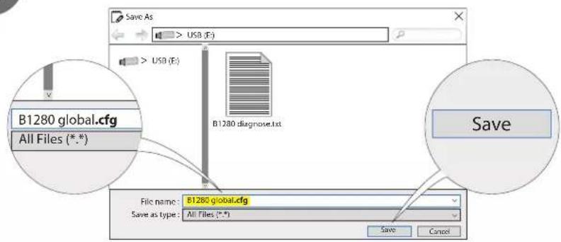
- Save the configuration
After configuring the parameters, save the text file under: B1280 global.cfg.
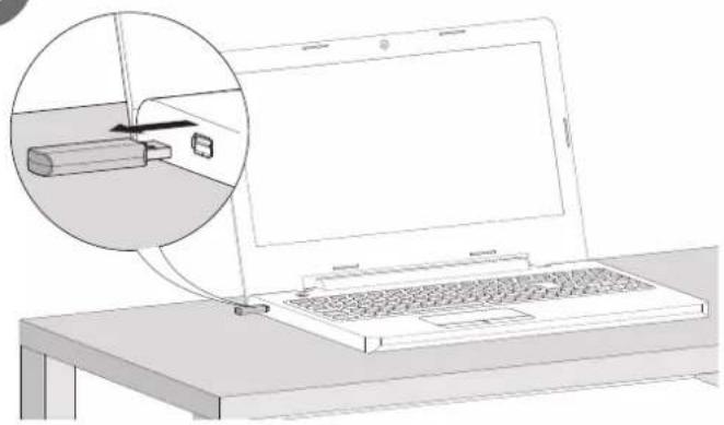
1
2

3

natural_image
Line drawing of a laptop with an inset showing a battery being inserted into it (no text or symbols present)4

natural_image
Diagram of a computer interface showing internal components and a magnified view of a device with an arrow pointing to a component (no text or symbols present)5
6
Wait 60 seconds before cutting it off.
7
natural_image
Diagram of an electronic device showing internal components and a magnified view of a device with a directional arrow (no text or symbols present)8

natural_image
Diagram of a hand pressing a button on an electrical switch (no text or symbols present)15 s

steady green
natural_image
Simple line drawing of a device with a vertical line and rectangular body, no text or symbols present.
Read the key again to check that all of the parameters have been taken into account.
11. Finalisation
natural_image
Cross-sectional diagram of a device showing internal components and a close-up view of a mechanical component (no text or symbols)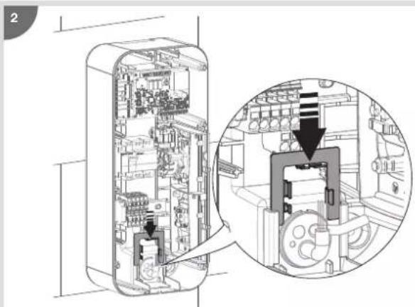
natural_image
Technical diagram of a mechanical device interior showing internal components and a magnified view of the internal structure (no text or labels)


natural_image
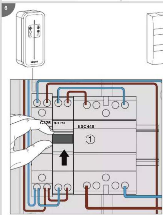
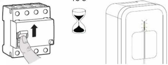
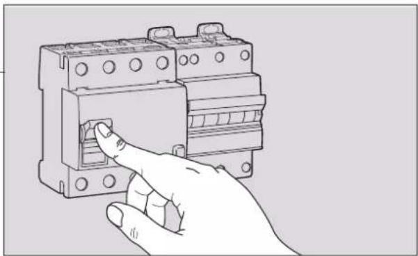
Hand inserting a fuse into an electrical switch (no text or symbols visible)12. Contactor and shunt trip function test
It is possible to quickly test the contactor and the shunt trip coil (Shunt Trip function).
- CONTACTOR TEST
- Put on the PPI (Personal Protective Equipment).
- Remove the charging station cover.
- Switch off the power via the charging station's circuit breaker.
- Disconnect the connector from the HMI board.
- Set the encoder wheel to position B.
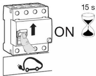
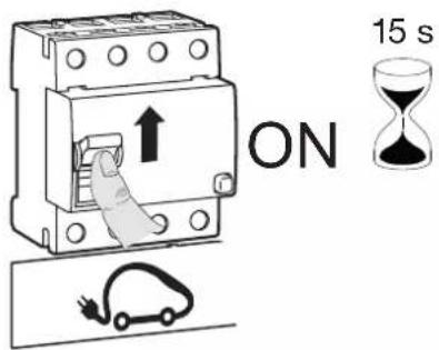
- Switch on the charging station
natural_image
Top-down schematic of an electronic circuit board layout with components like capacitors, resistors, and connectors (no text or labels)2 options:
- The contactor closes (listen for the "click"). Use a multimeter to measure the pole-by-pole voltage at the 40 A contactor outputs, ideally with the vehicle connected.
The voltages measured must be between 200 V\~ and 240 V\~.
If the voltages are correct, the contactor is operational:
a) switch off from the charging station circuit breaker,
b) connect the HMI ribbon cable,
c) reset the encoder wheel to the desired intensity (see "configuration" chapter),
d) switch on from the charging station circuit breaker.
or
- If the contactor does not close (no sound) or the voltages measured are not correct, the contactor malfunctions:
a) switch off from the differential circuit breaker of the electrical board,
b) replace the contactor,
c) reset the encoder wheel to the desired intensity (see "configuration" chapter),
d) connect the HMI ribbon cable,
e) switch on from the differential circuit breaker of the electrical board.
7. Close the charging station cover
• TEST OF THE SHUNT TRIP FUNCTION.
- Put on the PPI (Personal Protective Equipment).
- Remove the charging station cover.
- Switch off the power via the charging station's circuit breaker.
- Disconnect the connector from the HMI board.
- Set the encoder wheel to position A.
- Switch on the charging station
2 options:
- After 10 seconds, the MZ203 coil is activated. The charging station protections located on the panel trip and the bollard is no longer powered.
a) reset the encoder wheel to the desired intensity (see "configuration" chapter),
b) connect the HMI ribbon cable,
c) switch on from the differential circuit breaker of the electrical board.
or
- The MZ203 coil does not activate:
a) switch off from the differential circuit breaker of the electrical board,
b) check the wiring of the shunt trip function,
c) connect the HMI ribbon cable,
d) switch on from the differential circuit breaker of the electrical board.
7. Close the charging station cover
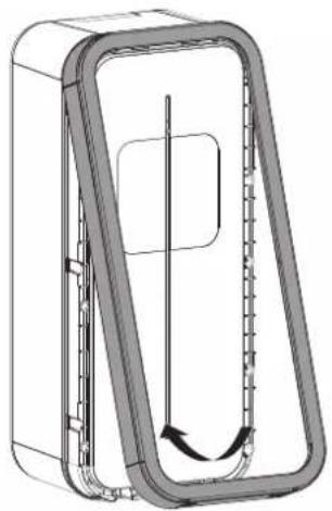
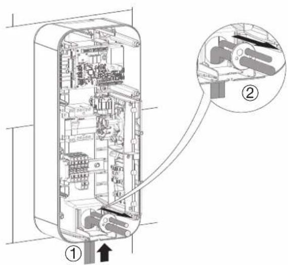
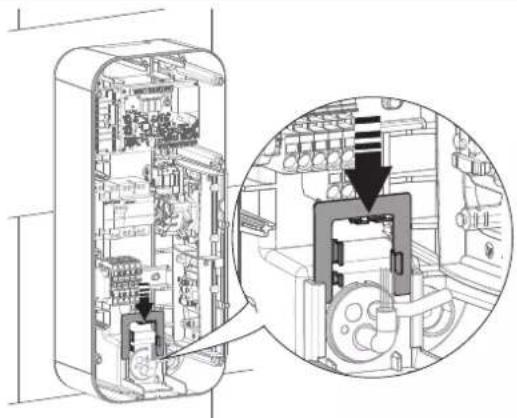
13. Closing the charging station
1
2
natural_image
Technical line drawing of a mechanical component with internal flow arrows (no text or symbols)3

natural_image
Diagram of a refrigerator with a hand inserting a cable into the front panel, showing internal rotation and clockwise mechanism (no text or symbols)
4
- Select the correct sticker.
Sticker to be used when the locking key is not used

Sticker to be used when the locking key is used

- First remove the back of the sticker.
- Adjust the sticker in the intended area.

- Remove the protective film from the front of the sticker.

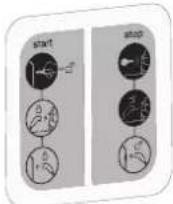
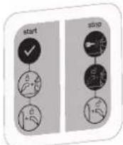
14. Charging station operation

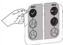
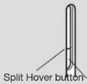
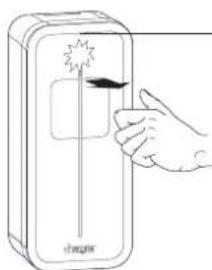
For the hover button to work correctly, the thumb must cover the split part and the bottom of the lighting strip.


natural_image
Illustration of a hand holding a pen with a green checkmark icon (no text or symbols)
If the key lock has been activated in the charging station configuration/setting, then for any action on the station such as vehicle charging, mode change, forcing the charge, charge release, the station must be in the unlocked position key in "open padlock" position.
14.1. Selecting the charging mode
The XEV1Kxx charging stations have three charging modes:
- Immediate charging mode (blinking yellow):
This mode charges an electrical vehicle as soon as it is connected.
- Deferred charging mode (blinking blue):
In this mode, the start of charging is delayed and only permitted during reduced tariff time periods.
Charging stops when it is complete.
- Exclusive deferred charging mode (blinking white):
In this mode, charging is delayed and only permitted during reduced tariff time periods.
Charging stops when the reduced tariff time period comes to an end, even if charging is not complete.
Follow the steps below to select these modes:
1
There is no electric vehicle connected to the charging station.
natural_image
Diagram of a device with a cable connector and a 3D model, showing no text or symbols.2
The charging station is unlocked and the lighting strip has a steady green light.

3
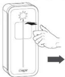
To display the current charging mode, place your thumb on the hover button until the lighting strip flashes (min. 10 secs) then remove it.


| Flashing yellow | Immediate charging mode |
| Flashing blue | Deferred charging mode |
| Flashing white | Exclusive deferred charging mode |
4
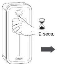
To switch from one mode to the other, place your thumb on the hover button for 2 seconds then remove it. The lighting strip changes colour, indicating the new charging mode selection.


flowchart
graph TD
    A["Immediate charging mode"] --> B["Deferred mode"]
    B --> C["Have deferred charging mode"]
    C --> A
5
To save a new charging mode:
Wait 20 secs.
The lighting strip flashes quickly for 5 seconds depending on the charging mode selected.

20 secs.


OR
Connect the electric vehicle to the charging station

natural_image
Diagram showing a car charger connected to a cable with connectors, no text or symbols present14.2. Forcing the charge
1
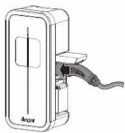
Connect the electric vehicle to the charging station.

natural_image
Diagram of a device with an attached cable and connector, showing no text or symbols2
Place your thumb on the hover button for 2 seconds then remove it. The lighting strip starts to pulse green.

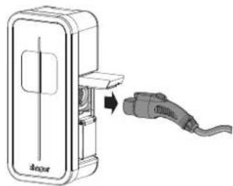
14.3. Unlocking the charging cable
If the charging cable is locked on the charging station, you can release it by following the procedure below. The charging station must be unlocked (key to ON position):
1
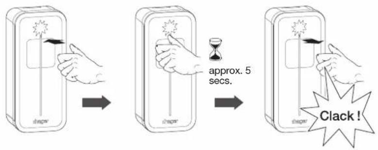
Push the plug to the bottom of the socket in the charging station.
natural_image
Technical line drawing of a device with a cable and connector (no text or symbols)2
Place your thumb on the hover button for approximately 5 seconds then remove it. You will hear a "click" as it unlocks.
3
The lighting strip flashes green/white. You can remove the charging cable. This procedure can be done several times in a row.

natural_image
Diagram of a device with an attached plug, showing internal components and a directional arrow (no text or symbols)15. Charging station diagnostic
15.1. Introduction
The charging station incorporates a set of control parameters to establish a diagnosis during all phases of its operation.
The results are provided in the B1280 diagnose .txt file when the USB flash drive is inserted into the USB port of the charging station controller board.
The B1280 diagnose .txt file is made up of 2 areas:
- A first area providing all of the charging station configuration parameters from the [Config] field to the [Tic] field. For more details, refer to Chapter 11: Charging station Configuration.
- A second area providing a complete diagnosis of the charging station and starting with the [Diagnose] field.

DANGER WARNING: if a live diagnosis is required, please equip yourself with PPE (Personal Protective Equipment).
15.2. Diagnostic parameters and their explanations
This chapter sets out the diagnostic function of the B1280 controller board.
Description:
The diagnostic function is implemented to provide detailed information on the current state of the charging station.
- The diagnostic is written automatically when the USB flash drive is inserted.
- On a B1280 controller, equipped with an optional XEVA220 Wi-Fi card, access is via the Wi-Fi network instead of USB.
The diagnostic information is divided into sections, each of which is described below.
Each section may vary depending on the configuration of the Witty charging station.
Example of a Diagnose function:

The parameters of the Diagnose function cannot be modified
15.2.1. Information
This section concerns the current software version, the type of board and other charging station data.
| [Information] | |
| Version = 7.0.1.0 | |
| Hardware = B1280 | |
| D/N_Timer = 0 s | |
| Blackout_timer = 0 s | |
| Wifi = absent | |
| Field Possible value | Note | |
| Version = x.x.x.x Witty charging station software version | ||
| Hardware = B1280 | ||
| D/N_Timer = | Minutes | The current status of the D/N timer, if not at zero, represents the time remaining in minutes before charging begins. |
| Blackout_timer = | 0-60 Seconds | Current value of the blackout timer after a power failure. If it is not zero, it represents the time remaining in seconds before charging restarts. |
| Wifi = Absent; Present | ||
15.2.2. Inputs
This section deals with the current status of the input data.
| [Inputs] | |
| Slider = | Delayed inclusive |
| Current_selector = | 32 A |
| Tariff = | High tariff |
| CHP_Input = | Open (unused) |
| Temp = | 27°C |
| Key_Switch = | Unlocked |
| Installation_phases = | Three-phase |
| Field | Possible value | Note |
| Slider = | Immediate; Delayed; Pin (Test mode) | Immediate; Delayed; Pin (Test mode) |
| Current_selector = | 13 A; 16 A; 20 A; 25 A; 32 A | Charging current set |
| Tariff = | Low tariff; High tariff | Off-peak tariff; Peak tariff |
| CHP_Input = | Open; Close | External signal status (Open; Closed) |
| Temp = | [0-125]°C | Temperature of the B1280 controller board |
| Key_Switch = | Locked; Unlocked | Charging station locked/Charging station unlocked |
| Installation_phases = | Single-phase; Three-phase Single-phase; Three-phase | |
15.2.3. Socket
This section concerns the current status of the sockets.
Mode 3 T2S secured
| [Socket1] | ||
| BP_Timer | 0 s | |
| EVSE_Contactor | Closed | Closed contactor |
| EV_consumption_p1 = | 16 A | Phase 1 consumption (charging station terminal block) |
| EV_consumption_p2 = | 16 A | Phase 2 consumption |
| EV_consumption_p3 = | 16 A | Phase 3 consumption |
| Ihm_status | EV Charging(led cycle ~10s) | IHM status, slow pulsing, chargin in green |
| Charging_Mode | 3 | Mode 3 charging |
| Cable | 32 A | 32A cable |
| Ctrl_pilot | Typical | |
| State | C2 (16 A) | C2 = EV ask for charging, 16A is that the charging station purpose via PWM |
| Field Possible value | Note | |
| BP_Timer 0-60 Seconds Time remaining to change the D/N mode with the EVSE_Contactor Open; Close Contactor Open; Closed | BP | |
| EV_consumption nA n: Instantaneous charging station current | ||
| HMI_status " | OffReady Ready tic faultyReady tic idleReady (Purple)Waiting for EV reactionWaiting for EV (de)connectionWaiting for authorization signal ie:\D/N; CHP; TIC;Blackout resume timerWaiting for authorization signal ie:\D/N; CHP; TIC;Blackout resume timer; M3 releaseWaiting for Power availability or M3 releaseWaiting for Power availability / Wifi startWaiting for Power request from EVEV Charging (led cycle ~10s)EV Charging (led cycle ~20s)EV Charging with faulty TICEV Charging with standby TICEV Charging after Load SheddingEV don't request chargingEV don't request charging (tic faulty)EV don't request charging (tic standby)Fatal ErrorError" | "This corresponds to the LED statuses. Each of these could be followed by the Access Point (AP) on the B1280 controller. OffReady Ready tic faultyReady tic idleReady (Purple)Waiting for EV reactionWaiting for EV (de)connectionWaiting for authorisation signal, i.e.D/N; CHP; TIC; blackout timer in case of power failureWaiting for authorisation signal, i.e.:D/N; CHP; TIC; blackout timer; M3 versionWaiting for power supply or M3 versionWaiting for power availability/Wi-Fi start-up (depending on charging station version)Waiting for Power request from EV Vehicle charging in progress (LED cycle approx. 10s)EV Charging (led cycle approx. 20s)EV Charging with faulty TICEV Charging with standby TICEV Charging after Load SheddingEV don't request chargingEV don't request charging (tic faulty)EV don't request charging (tic standby)Fatal ErrorError" |
| Charging_Mode 2;3 Charging mode 2 or 3 | ||
| Cable Failed; 13 A; 20 A; 32 A; 63 A; Not Connected; Unknown | "Cable value: Failed; 13 A; 20 A; 32 A; 63 A; Not Connected; UnknownFailure means that the cable resistance coding is outside of tolerance" | |
| Ctrl_pilot Standard; Simplified -> Current Max 10 A Standard; Simplified -> | Current Max 10 A | |
| State | A1; A2; B1; B2; C1; C2; D1; D2; E; F; U: as defined in the standard IEC 61851-1 | A1; A2; B1; B2; C1; C2; D1; D2; E; F; U: as defined in the standard IEC 61851-1 |
15.2.4. TIC
This section concerns the communication protocol between the main meter and the charging stations
| [TIC] | |
| Activity = Active | |
| Data = Valid (24587) | |
| Mode = History | |
| Isousc = 45 A | |
| linst = 1 A | |
| Tariff = HP. (High tariff) | |
| Field Possible value Note | ||
| Activity Inactive; Active | Inactive; Active → Active means that a frame has been received | |
| Data Invalid; Valid | Invalid; Valid → Valid means that the TIC frame is correct | |
| Mode "Standby | StandardHistoryThree-phase standardThree-phase historyGreenchargingUnknown" | StandbySingle-phase standardSingle-phase historyThree-phase standardThree-phase historyGreenchargingUnknown |
| Iprod n A n is the current produced. Only displayed if Ecolo = Active | ||
| Isousc | n A n is the maximum subscribed current. Only displayed if Ecolo = Inactive | |
| linst | n A | n is the instantaneous current consumed by the installation. Only displayed if Ecolo = Inactive |
| linst_x | n A | n is the instantaneous current consumed by the installation during phase x. Only displayed with a three-phase TIC |
| Tariff | .. If 2 points are present behind a rate, it is followed by the wording Low (advantageous cost) or High (normal/high cost)HC.. HC/HP tariff: Off peak hoursTempo tariff: Off peak hours, blue dayTempo tariff: Off peak hours, red dayTempo tariff: Off peak hours, white dayNormal hours tariffHP.. HP/HC tariff: Peak hoursTempo tariff: Peak hours, blue dayTempo tariff: Peak hours, red dayTempo tariff: Peak hours, white dayEJP tariff: Mobile peak hoursHourly tariffTariff1 to Tariff10 only supplied by the Linky meter in standard TIC.The tariffs used depend on the tariff contract selected by the customer, depending on their energy supplier. | |
| HC.. HCJB HCJR HCJW HN.. HP.. HPJB HPJR HPJW PM.. TH.. Tariff1 Tariff2 Tariff3 Tariff4 Tariff5 Tariff6 Tariff7 Tariff8 Tariff9 Tariff10 | ||
15.2.5. Error
| [Error] | |
| err_1: No error | |
| err_2: | |
| Field | Possible value | Note |
| "err_x(x is the number of the:- socket 1 / T2S socketor- socket 2 / TE socketE.g.: 1, 2)" | "No Error""Cable Failure""CP Short Circuit Failure""Over Consumption""Ventilation Error""Load Shedding Failure""CP Failure""DC Current Failure""Welded Contact Failure 1""DC Sensor Failure"" | "In the event of an error, the number of flashes is also specified so that the LED error code is known (see Chapter 16. Indicators).No ErrorCable FailureCP Short Circuit FailureOver ConsumptionVentilation ErrorLoad Shedding FailureCP FailureDC Current FailureWelded Contact Failure 1DC Sensor Failure" |
15.2.6. Maintenance
| [1] | |
| Socket = 1 | |
| T_connect 16428 | s |
| T_charge = 11602 | s |
| Energy = 35680 | |
| [Maintenance] | |
| Ch_duration_1 = 6 | 25 h |
| Cycles_1 = 179 | |
| Ch_duration_2 = | 1 h |
| Cycles_2 = 5 | |
| Field Possible value Note | ||
| Ch_duration_x H: | M:S Total charging time of the socket x or x = 1 (T2S) or 2 (TE). | |
| Cycles_x Integer | Number of contactor opening and closing cycles x or x = 1 (T2S) or 2 (TE). | |
15.3. Log file
A Log file named "B1280 logs.csv" is written to the flash drive when it is inserted into the USB port of the controller board. This file informs the installer about the saved charging sessions by providing various information during charging, such as:
- The number of socket 1 (T2S) or 2 (TE)
- The energy consumed during the charge
- The time in seconds to session start
- The time in seconds to session stop
- The time in seconds to charging start
- The time in seconds to charging stop
- The session time in seconds
- The charging time in seconds
- The error code
As memory is limited, only the last session recordings are kept.
16. Indicators
16.1. Normal operation
| Lighting strip Charging station status | |
 off off | Charging station off |
| steadygreen | Charging station ready for charging or charging complete |
| [TOX8]flashinggreen | Charging station awaiting changeover to reduced tariff schedule |
 pulsinggreen pulsinggreen | Electric vehicle charging |
| Lighting strip Charging station status | ||
 | flashing blue | Electric vehicle awaiting charge and charge not finalised |
| [KASW] | pulsing blue | Electric vehicle charging after an interrupted charge (load shedding for example) |
 | [627Y] flashing green/ white | Charging station waiting for electric vehicle connection or disconnection |
16.2. Anomalies
| Lighting strip Cause | What to do | |
| steady red | Three possible faults:1. TIC fault. If charging is possible (pulsing red), the TIC fault is confirmed.2. The 40 A contactor is stuck3. The DC detection probe is defective or disconnected. | Find the source of the failure and repair it. |
| [7H66]pulsing red | The electric vehicle charges in degraded mode (charge limited to 7 A in single phase and 13 A in three phase). TIC is absent. | Find the source of the failure and repair it. |
 rapid flashing green rapid flashing green | The charging station detects that the electric vehicle generates a direct current greater than 6 mA. After 4 detections, it changes to flashing red (x9 see table on next page). | The customer must call their car dealership |
| Lighting strip | Number of flashes | Cause What to do | |
 flashing red flashing red | 1 Defective or unsupported cable Change the cable | ||
| 2 | The detection function of an electric vehicle does not work | Change the cable if the problem still persists after replacement:1. Check the integrity of the car and charging station sockets2. Call the Technical Assistance Service (TAS) | |
| 3 | The electric vehicle does not respect the power limit imposed by the charging station | Unplug the vehicle and try charging again. If the problem persists, call the TAS | |
| 4 | The charging station is not compatible with this vehicle because it requires the management of ventilation in the vehicle environment; ventilation that is not managed by this station | Charge the vehicle via another charging station that is compatible with it | |
| 6 | The charging station does not receive the correct charging authorisation from the electric vehicle | Change the cable if the problem still persists after replacement: call the Technical Assistance Service (TAS) | |
| 9 | The electric vehicle generates a direct fault current, preventing charging | Detection of a direct current greater than 6 mA in the vehicle power supply.The customer must call their car dealership | |
17. Internal wiring of the charging stations
• T2 single-phase charging station power cabling: 1 Ph + N + E


• T2 three-phase charging station power cabling: 3 Ph + N + E


18. Electrical maintenance
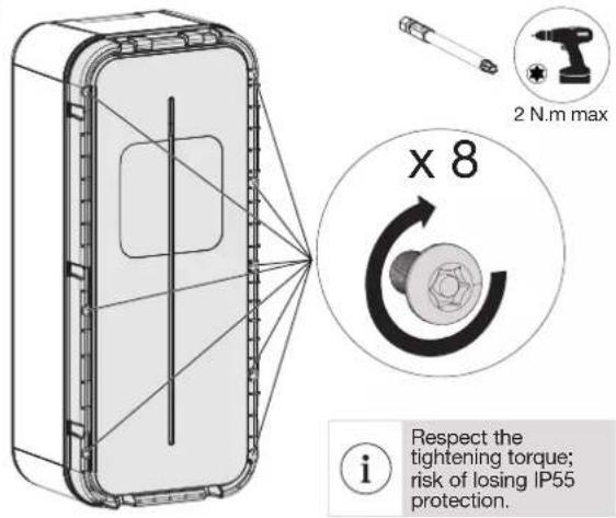
As with any fixed electrical installation product, it is important to check the tightness at the various connection points of the installation during the annual inspection. They must be in phase with the following torques:

Respect the tightening torque; risk of electrical shock.
Tightening torques

2 N.m circuit breaker

2 N.m energy meter

Contacteur 3N.m

Contacteur 2N.m

After opening the charging station for wiring, configuration or maintenance reasons, you must put the cover back in place and adhere to the tightening torques. Refer to chapter 13. Closing the charging station.

For more details, refer to the maintenance manual for charging stations 6LE007370A.
19. Technical characteristics
- Charging station
| Environmental conditions | |
| Usage temperature -25°C to +50°C | |
| Storage temperature -35°C to +70°C | |
| Relative humidity 5% to 95% | |
| Protection IP 55 - IK 10 | |
| Maximum altitude of operation 2000 m | |
| Degree of pollution 3 | |
| Use intended for use by ordinary people | |
| Electrical characteristics | |
| Voltage 230 V~ / 400 V~ (three-phase version) -15% / +10% | |
| Usage frequency 50/60 Hz +/- 1% | |
| Nominal insulation voltage Ui 250 V~ / 500 V~ | |
| Standby power consumption 1,7 W | |
| Charging station electrical protection | 40 A circuit breaker, C curve, energy limitation class I2t 3, on a circuit that cannot supply more than 6 kA in short-circuit (or equivalent) |
| Electrical protection of the charging station if Charging mode 2 supplied | 16 A circuit breaker, C curve, energy limitation class I2t 3, on a circuit that cannot supply more than 6 kA in short-circuit (or equivalent). |
| Maximum charging current/power Mode 3 T2/T2S socket (depending on version) | 32 A - 7 kW (single-phase version) / 32 A - 22 kW (three-phase version)16 A - 4 kW (single-phase version) / 16 A - 11 kW (three-phase version) |
| Maximum charging current/power Mode 2 TE socket (depending on version) | 16 A - 4 kW |
| Electrical protection rating Class 1 (earth connection) | |
| Overvoltage category 3 | |
| Earth connection diagram TN-S, TN-C-S, TT | |
| Minimum/possible wiring | 10 mm2 in single or multi strand/16 mm2 in multi strand.Only the use of a copper conductor is authorised. |
| Mechanical characteristics | |
| Weight 6.2 kg | |
| Maximum weight supported by the cable support affixed to the charging station | 7 kg |
| Height | 549 mm |
| Width | 250.5 mm |
| Depth | 173 mm |
| Classification | |
| Power input | Electric Vehicle (EV) power system connected to the AC power supply network (permanently connected) |
| Power output | alternate current power system for EV |
| Environmental and usage conditions | indoor and outdoor use |
| Location of | equipment for restricted access areas and unrestricted access areas |
| Type of mounting | surface mounting on wall mounting, on stand, fixed post, column and pipe.Installation in a horizontal position on the ceiling or on the floor is prohibited |
| Category equipment | 1 |
| Charging mode | mode 3 via T2/T2S socket and mode 2 via TE socket depending on version |
| Adaptor | no plug adapter can be used between the charging station and the charging cable or between the charging cable and the car |
| Cable extension | the charging cable cannot be extended. The charging cable must be in one piece and a maximum length of 7 m |
- Identification of vehicle compatibility

20. Lexicon
- Remote reading cable: specific cable to establish a remote reading bus (one or more wire connections) between devices and communicating under the EURIDIS protocol. 2 pair 6/10 twisted cable (either reinforced or not) depending on the installation constraints according to the NFC 33-400 standard.
- Dynamic charging: this function, integrated in charging stations fitted with a TIC board or in combination with a TIC simulator, automatically adapts the vehicle's charging power according to the domestic power available. This function prevents a protection device (circuit breaker, etc.) or the main differential circuit breaker from being opened.
- CHP: Combined Heat and Power. Abbreviation used in cogeneration systems. Examples:
- Combined heat and electricity production system using gas or diesel combustion
- Photovoltaic or wind power system
- D/N: Day / Night. It is used in the context of tariff subscriptions such as Peak hours/Off-peak hours, Tempo ... and, more generally, subscriptions at reduced tariffs.
- HMI: Human Machine Interface. The charging station is composed of an LED indicator light and a hover button located at the base of the indicator light serving as a virtual button.
- T2/T2S: T2/T2S (S for secure) sockets or connectors are connection devices for charging station and electric cars, and are standardised and integrated in a large majority of them.
• TE: the TE socket is a French 16 A socket used exclusively to charge the battery of vehicles such as bicycles, scooters, etc. - ST: Shunt Trip or Trigger. Function used to cut the power to the charging station in the event of a fault.
- TIC: Customer tele-information. French white electric energy meters and the Linky meter have a TIC output allowing individual power management; they also monitor its energy consumption in real time. French white electronic meters incorporate a historical TIC. The new Linky meter integrates the historical TIC and standard TIC. However, a single TIC is active. By default at installation, the historical TIC is activated by the energy supplier. To switch from historical TIC to standard TIC, ask the customer to call their energy supplier and implement service F185. This service switches the historical TIC to the standard TIC without intervention on the customer's site.
-
USB: Universal Serial Bus. USB is a computer bus standard for connecting devices to a computer. The USB port used on the controller board enables you to connect a USB flash drive to:
-
configure the charging station,
• perform a charging station diagnosis, - update the software on the controller board.

How to dispose of this product (waste electrical and electronic equipment). (Applicable in European Union countries and other European countries with selective collection systems). This symbol on the product or its documentation indicates that it is not a standard, proportional, or proportional method.
Must not be disposed of at the end of its line with other household waste. As uncontrolled disposal of waste can harm the environment or human health, please separate it from other types of waste and recycle it responsibly. You promote the sustainable reuse of material resources. Individuals are asked to contact the distributor who sold them the product or to check with their local authority to find out where and how they can dispose of this product so that it is recycled in an environmentally friendly manner. Companies are invited to contact their suppliers and consult the conditions of their sales contract. This product should not be disposed of with other commercial waste.
Can be used everywhere in Europe (€) and Switzerland
Hager hereby declares that the charging station products referenced XEV1Kxxx comply with the RED 2014/53/EU directive.
The CE declaration can be viewed at: www.hagergroup.net.
Recommendations
Any access to internal areas, beyond the areas described in this manual, is prohibited and voids the warranty and any other form of support. It can be damaging to the parts and/or to the electronic components. These products have been defined so that they do not have to be accessed during product implementation and maintenance operations.
Non-contractual document, subject to modification without notice.
Inhaltsverzeichnis
natural_image
Line drawing of a mechanical device with a labeled component 'shager' (no other text or symbols)natural_image
Technical line drawing of a rectangular device with internal components, labeled (a), (b), and (c) for scale (no text or symbols on the diagram itself)| a (mm) 549 |
| b (mm) 250,5 |
| c (mm) 173 |

natural_image
Line drawing of a rectangular box with a central slot and a rectangular cutout (no text or symbols)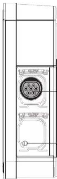
natural_image
Technical line drawing of a mechanical component with internal circular features and mounting holes (no text or symbols)natural_image
Technical line drawing of a mechanical device mounted on a vertical support frame (no text or symbols)5. Installation
5.1. Öffnen


natural_image
Technical line drawing of a mechanical device with an open lid and internal compartments (no text or symbols)2

natural_image
Technical line drawing of a battery pack assembly showing internal components and mounting points (no text or symbols)3
natural_image
Technical line drawing of a mechanical housing component with an inset showing a gear mechanism (no text or symbols)5.2. Befestigung


natural_image
Technical illustration of a door panel and its internal component, showing alignment and polarity (no text or symbols)

natural_image
Cross-sectional diagram of an electronic device showing internal components and a magnified inset of a mechanical assembly (no text or symbols)2

natural_image
Diagram of a computer interface showing an inserted device and its internal components, with a magnified inset highlighting the device's internal structure (no text or symbols present)3
grünes Dauerlicht
natural_image
Simple line drawing of a device with a vertical line and a rectangular button (no text or symbols)i
natural_image
Diagram of a mechanical component with a downward arrow indicating a force or movement (no text or symbols present)natural_image
Pure technical line drawing of a mechanical component or housing (no text or symbols)5

natural_image
Diagram of an electronic device showing internal components and a magnified view of the internal structure (no text or symbols)6
Ladestation XEV1K11T2.
2
3
natural_image
Line drawing of a laptop with an inset showing a battery being inserted into it (no text or symbols present)4

natural_image
Diagram of a computer interface showing internal components and a magnified view of a device with an arrow pointing to a component (no text or symbols present)5

6
natural_image
Diagram of an electronic device showing internal components and a magnified view of the internal structure (no text or symbols present)8

natural_image
Hand inserting a switch into an electrical component (no text or symbols visible)15 s

grünes Dauerlicht
natural_image
Simple line drawing of a door with a handle and lid, no text or symbols presentnatural_image
Cross-sectional diagram of a device showing internal components and a magnified view of a mechanical component (no text or symbols)2

natural_image
Technical diagram of an electronic device interior showing internal components and a magnified view of the internal structure (no text or labels)3
natural_image
Technical diagram of an internal electrical device with a magnified inset showing the cable being inserted (no text or labels present)natural_image
Technical diagram of an electronic device showing internal components and wiring, with no visible text or symbols.6


natural_image
Hand inserting a button into an electrical fuse block (no text or symbols visible)natural_image
Top-down schematic of an electronic circuit board layout with components like capacitors, resistors, and connectors (no text or labels)2 Möglichkeiten:
natural_image
Technical line drawing of a mechanical component with internal flow arrows (no text or symbols)3

natural_image
Diagram showing a hand holding a device with a close-up view of the internal components (no text or symbols present)

natural_image
Diagram of a device with a plug inserted into a box labeled '3coper', showing no text or symbols beyond the label.2
3

natural_image
Diagram showing a car door panel connected to a cable with a connector, alongside a close-up of the cable being inserted (no text or symbols present)natural_image
Diagram of a device with an attached cable and connector, showing no text or symbolsnatural_image
Technical line drawing of a device with a clamped cable and labeled 'Anger' (no text or symbols beyond label)natural_image
Diagram of a device with an attached plug, showing internal components and a cable (no text or symbols)| [Inputs] | |
| Slider = Delayed inclusive | |
| Current_selector = 32 A | |
| Tariff = | High tariff |
| CHP_Input = | Open (unused) |
| Temp = | 27 °C |
| Key_Switch = | Unlocked |
| Installation_phases = | Triple-phase |
| [TIC] | |
| Activity = Active | |
| Data = Valid (24587) | |
| Mode = Historie | |
| Isousc = 45 A | |
| linst = 1 A | |
| Tariff = HP.. (High tariff) | |
| [1] | |
| Socket = 1 | |
| T_connect 16428 | s |
| T_charge = 11602 | s |
| Energy = 35680 | |
| [Maintenance] | |
| Ch_duration_1 = 625 h | |
| Cycles_1 = 179 | |
| Ch_duration_2 = | 1 h |
| Cycles_2 = | 5 |


natural_image
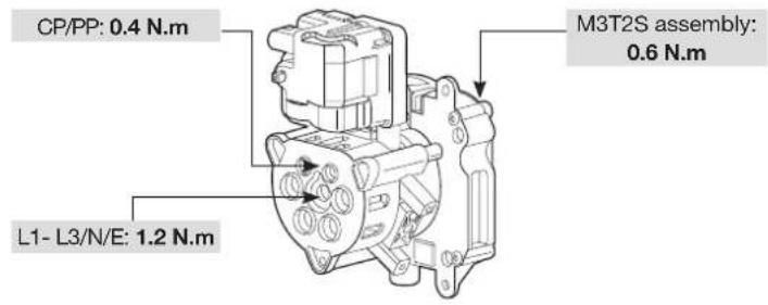
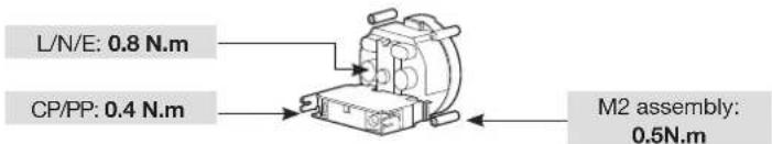
Technical line drawing of a mechanical assembly with no visible text or symbolsMontage M3T2S: 0,6 Nm
L/N/PE: 0,8 Nm
CP / PP: 0,4 Nm
Montage M2: 0,5 Nm

natural_image
Line drawing of a mechanical device with a door and internal components (no text or symbols)natural_image
Technical line drawing of a rectangular device with internal components, labeled (a), (b), and (c) for dimension reference (no text or symbols on the diagram itself)| a (mm) 549 |
| b (mm) 250,5 |
| c (mm) 173 |

natural_image
Line drawing of a rectangular box with a central slot and a rectangular cutout (no text or symbols)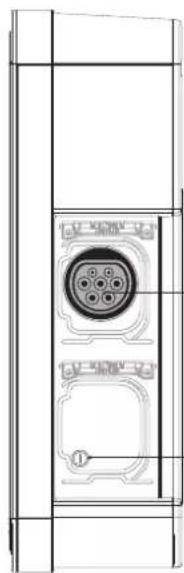
natural_image
Technical line drawing of a door panel with a circular connector and mounting base (no text or symbols)natural_image
Technical line drawing of a mechanical device mounted on a vertical support frame (no text or symbols)5. Installazione
5.1. Apertura

natural_image
Technical line drawing of a mechanical device with an open lid and internal compartments (no text or symbols)2
natural_image
Technical line drawing of a battery pack assembly showing internal components and mounting points (no text or symbols)3
natural_image
Technical line drawing of a mechanical housing component with internal curved and linear features (no text or symbols)5.2. Fissaggio


natural_image
Diagram showing a door panel with 'sheager' label and a separate electrical component with three switches (no text or symbols on the main components)

natural_image
Cross-sectional diagram of an electronic device showing internal components and a magnified inset (no text or symbols)2

natural_image
Diagram showing a computer interface with an inserted cable and a close-up of the cable connector (no text or symbols visible)3

verde fisso

natural_image
Simple line drawing of a device with a vertical line and a rectangular button (no text or symbols)i
natural_image
Diagram of a mechanical component with a downward arrow indicating a force or movement (no text or symbols present)luce spenta
natural_image
Pure technical line drawing of a mechanical component or housing (no text or symbols)5

natural_image
Diagram showing a computer interface with an inset close-up of a battery component (no text or symbols visible)6

natural_image
Line drawing of a laptop with an inset showing a battery being inserted into it (no text or symbols present)4

natural_image
Diagram of a computer interface showing an open circuit board with a close-up inset of the component (no text or symbols visible)5
6
natural_image
Diagram of a computer interface showing internal components and a magnified view of a device (no text or symbols present)8

natural_image
Cross-sectional diagram of a device showing internal components and a magnified view of a mechanical component (no text or symbols)2
natural_image
Technical diagram of a mechanical device interior showing internal components and a magnified view of the internal structure (no text or labels)3
natural_image
Technical diagram of an internal electronic device showing internal components and a magnified view of the device's internal structure (no text or labels present)natural_image
Technical diagram of an electronic device showing internal components and wiring, with no visible text or symbols.6


natural_image
Hand inserting a fuse into an electrical switch (no text or symbols visible)natural_image
Top-down schematic of an electronic circuit board layout with components like capacitors, resistors, and connectors (no text or labels)2 possibilità:
natural_image
Technical line drawing of a mechanical component with internal flow arrows (no text or symbols)3

natural_image
Diagram of a door switch mechanism showing hand placement and rotary dial (no text or symbols)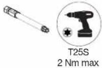

natural_image
Diagram of a device with an attached plug and label 'dinner' (no text or symbols on the diagram itself)natural_image
Diagram showing a car door panel connected to a cable with a connector, alongside a close-up of the cable being inserted (no text or symbols present)14.2. Ricarica forzata
natural_image
Diagram of a device with a cable being inserted into a box (no text or symbols visible)natural_image
Technical line drawing of a device with a cable and labeled ports (no readable text or symbols)natural_image
Diagram of a device with an attached plug, showing internal components and a directional arrow (no text or symbols)| [Informations] | |
| Version = 7.0.1.0 | |
| Hardware = B1280 | |
| D/N_Timer = 0 s | |
| Blackout_timer = 0 s | |
| Wifi = absent | |
| [Inputs] | |
| Slider = Delayed inclusive | |
| Current_selector = 32 A | |
| Tariff = | High tariff |
| CHP_Input = | Open (unused) |
| Temp = | 27 °C |
| Key_Switch = | Unlocked |
| Installation_phases = | Triple-phase |
| [TIC] | |
| Activity = Active | |
| Data = Valid (24587) | |
| Mode = Historique | |
| Isousc = 45 A | |
| linst = 1 A | |
| Tariff = HP.. (High tariff) | |
| [1] | |
| Socket = 1 | |
| T_connect 16428 | s |
| T_charge = 11602 | s |
| Energy = 35680 | |
| [Maintenance] | |
| Ch_duration_1 = 625 h | |
| Cycles_1 = | 179 |
| Ch_duration_2 = | 1 h |
| Cycles_2 = | 5 |


natural_image
Technical line drawing of a mechanical assembly with no visible text or symbolsMontaggio M3T2S: 0,6 N.m
L/N/T:0,8 N.m
CP / PP : 0,4 N.m
Montaggio M2: 0,5 N.m

- Installation
- Ouverture
- Fixation
- Câblage de la charge diff érée
- Modifier la configuration
- possibilités :
- Forcer la charge
- Diagnostic de la borne de charge
- Introduction
- Service Assistance Technique
- Safety advice
- Please read before carrying out any electrical wiring on the charging station
- Wiring the shunt coil (Shunt Trip function)
- Overview of the standard range
- Description of the exterior
- Description of the interior
- • Electrical composition of the base
- Opening
- Mounting
- Electrical protections for charging stations
- Power cabling
- Wiring the shunt coil MZ203 (Shunt Trip function)
- Wiring deferred charging
- Charging station configuration
- Charging station configuration procedure
- Maximum power setting
- - Configuration for compliance with EV Ready 1.4:
- - Configuration for compliance with ZE Ready 1.4:
- Modify the settings using a USB flash drive
- Modifying the configuration
- - Save the configuration
- 3->CHP unused
- 1->DN load shedding 7A*13A (mono*tr)
- 2->DN load shedding eA
- 3->DN unused
- 2->13
- 3->18
- Finalisation
- Contactor and shunt trip function test
- - CONTACTOR TEST
- options:
- or
- Close the charging station cover
- • TEST OF THE SHUNT TRIP FUNCTION.
- Closing the charging station
- Charging station operation
- Selecting the charging mode
- Forcing the charge
- Unlocking the charging cable
- Charging station diagnostic
- Diagnostic parameters and their explanations
- The parameters of the Diagnose function cannot be modified
- Information
- Inputs
- Socket
- TIC
- Error
- Maintenance
- Log file
- Indicators
- Normal operation
- Anomalies
- Internal wiring of the charging stations
- Electrical maintenance
- Technical characteristics
- Lexicon
- Recommendations
- Inhaltsverzeichnis
- Öffnen
- Befestigung
- Möglichkeiten:
- Installazione
- Apertura
- Fissaggio
- possibilità:
- Ricarica forzata
Brand : HAGER
Model : XEV1K11T2
Category : Switch