Turbo Cool AU5010 - Air-conditioner CALOR - Free user manual and instructions
Find the device manual for free Turbo Cool AU5010 CALOR in PDF.
User questions about Turbo Cool AU5010 CALOR
0 question about this device. Answer the ones you know or ask your own.
Ask a new question about this device
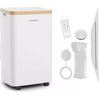
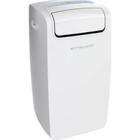
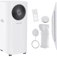
Download the instructions for your Air-conditioner in PDF format for free! Find your manual Turbo Cool AU5010 - CALOR and take your electronic device back in hand. On this page are published all the documents necessary for the use of your device. Turbo Cool AU5010 by CALOR.
USER MANUAL Turbo Cool AU5010 CALOR
natural_image
Technical line drawing of a mechanical device with a grid-patterned panel and base mount (no text or symbols)Schéma 1
- NETTOYAGE ET ENTRETIEN
natural_image
Diagram of a modular device with a grid panel and side-mounted unit, showing an open lid and directional arrow (no text or symbols)Schéma 2
MODE D'EMPLOI
Installation 1 - Installation mobile
natural_image
Top-down diagram of a room layout with furniture and a ceiling fixture (no text or symbols)Schéma 3
natural_image
Diagram showing indoor air conditioner unit with cooling pipes and ventilation system (no text or symbols)Schéma 4
Installation semi-permanente
text_image
(BI OK INOR MODE * * * SPID - + (AM30010)Please read the instruction manual and safety instructions carefully before using the appliance and keep the instruction manual for reference.
For your safety, this appliance complies with all applicable standards and regulations (Low Voltage, Electromagnetic Compatibility, Environmental directives, etc.).
 | WARNING(Risk of fire) | This unit uses a flammable refrigerant.If refrigerant leaks and comes in contact withfire or heating part, it will create harmful gasand there is risk of fire. |
 | Read the OPERATING INSTRUCTIONS carefully before operation | |
 | Service personnel are required to carefully read the OPERATINGINSTRUCTIONS and INSTALLATION MANUAL before operation | |
 | Further information is available in the OPERATING INSTRUCTIONS,INSTALLATION MANUAL, and the like | |
| Model name Symbol AU5010F0 AU5020F0 Unit | ||||
| Refrigerant | R290 | R290 | ||
| Total refrigerant amount | 193 | 233 | g | |
| Global warming potential | GWP | 3 | 3 | kg CO2 eq |
| Climate class | 16 – 35 | 16 – 35 | °C | |
| Cooling capacity | P_rated for cooling | 2,3 | 2,5 | W |
| Energy efficiency cooling | EER_d | 2,6 | 2,6 | |
| Energy Efficiency Class | A | A | ||
| Cooling power input | P_EER | 0,9 | 1,0 | kW |
| Voltage/frequency | 220-240V / 50Hz | 220-240V / 50Hz | V/Hz | |
| Power consumption in thermostat-off mode | P_TO | 1,0 | 1,0 | W |
| Power consumption in standby mode | P_SS | 0,5 | 0,5 | W |
| Electricity consumption | Q_SO | 0,9 | 1,0 | kWh/h |
| Sound Power Level | I_PDA | 65 | 65 | dB(A) |
| dimensions | WxHxD | 272 x 678 x 336 | 272 x 678 x 336 | mm |
| weight | 21,9 | 24,4 | kg | |
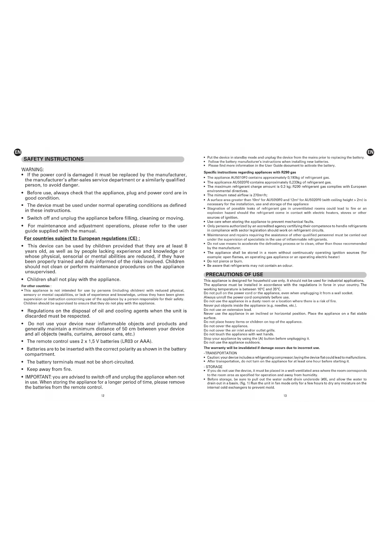
- If the power cord is damaged it must be replaced by the manufacturer, the manufacturer's after-sales service department or a similarly qualified person, to avoid danger.
- Before use, always check that the appliance, plug and power cord are in good condition.
- The device must be used under normal operating conditions as defined in these instructions.
- Switch off and unplug the appliance before filling, cleaning or moving.
- For maintenance and adjustment operations, please refer to the user guide supplied with the manual.
For countries subject to European regulations (CE) :
- This device can be used by children provided that they are at least 8 years old, as well as by people lacking experience and knowledge or whose physical, sensorial or mental abilities are reduced, if they have been properly trained and duly informed of the risks involved. Children should not clean or perform maintenance procedures on the appliance unsupervised.
• Children shall not play with the appliance.
For other countries :
- This appliance is not intended for use by persons (including children) with reduced physical, sensory or mental capabilities, or lack of experience and knowledge, unless they have been given supervision or instruction concerning use of the appliance by a person responsible for their safety. Children should be supervised to ensure that they do not play with the appliance.
- Regulations on the disposal of oil and cooling agents when the unit is discarded must be respected.
- Do not use your device near inflammable objects and products and generally maintain a minimum distance of 50 cm between your device and all objects (walls, curtains, aerosol cans, etc.)
- The remote control uses 2 x 1,5 V batteries (LR03 or AAA).
- Batteries are to be inserted with the correct polarity as shown in the battery compartment.
- The battery terminals must not be short-circuited.
- Keep away from fire.
- IMPORTANT: you are advised to switch off and unplug the appliance when not in use. When storing the appliance for a longer period of time, please remove the batteries from the remote control.
- Put the device in standby mode and unplug the device from the mains prior to replacing the battery.
- Follow the battery manufacturer's instructions when installing new batteries.
- Please find more information in the User Guide document to activate the battery.
Specific instructions regarding appliances with R290 gas
• The appliance AU5010F0 contains approximately 0,193kg of refrigerant gas.
• The appliance AU5020F0 contains approximately 0,233kg of refrigerant gas.
- The maximum refrigerant charge amount is 0.3 kg; R290 refrigerant gas complies with European environmental directives.
• The mimum rated airflow is 270m^3/h ;
- A surface area greater than 10m^2 for AU5010F0 and 12m^2 for AU5020F0 (with ceiling height >2m ) is necessary for the installation, use and storage of the appliance
- Stagnation of possible leaks of refrigerant gas in unventilated rooms could lead to fire or an explosion hazard should the refrigerant come in contact with electric heaters, stoves or other sources of ignition.
- Use care when storing the appliance to prevent mechanical faults.
- Only persons authorized by an accredited agency certifying their competence to handle refrigerants in compliance with sector legislation should work on refrigerant circuits.
- Maintenance and repairs requiring the assistance of other qualified personnel must be carried out under the supervision of specialists in the use of inflammable refrigerants.
- Do not use means to accelerate the defrosting process or to clean, other than those recommended by the manufacturer.
- The appliance shall be stored in a room without continuously operating ignition sources (for example: open flames, an operating gas appliance or an operating electric heater)
- Do not pierce or burn.
- Be aware that refrigerants may not contain an odour.
PRECAUTIONS OF USE
This appliance is designed for household use only. It should not be used for industrial applications. The appliance must be installed in accordance with the regulations in force in your country. The working temperature is between 16°C and 35°C.
Do not pull on the power cord or the appliance, even when unplugging it from a wall socket. Always unroll the power cord completely before use.
Do not use the appliance in a dusty room or a location where there is a risk of fire.
Never put objects inside the appliance (e.g. needles, etc.).
Do not use an extension lead.
Never use the appliance in an inclined or horizontal position. Place the appliance on a flat stable surface.
Do not place heavy items or children on top of the appliance.
Do not cover the appliance.
Do not cover the air inlet and/or outlet grills.
Do not touch the appliance with wet hands.
Stop your appliance by using the (A) button before unplugging it.
Do not use the appliance outdoors.
The warranty will be invalidated if damage occurs due to incorrect use.
-TRANSPORTATION
- Caution: your device includes a refrigerating compressor; laying the device flat could lead to malfunctions.
• After transportation, do not turn on the appliance for at least one hour before starting it.
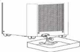
- STORAGE
- If you do not use the device, it must be placed in a well-ventilated area where the room corresponds to the room area as specified for operation and away from humidity.
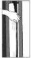
- Before storage, be sure to pull out the water outlet drain underside (#9), and allow the water to drain out in a basin. (fig. 1) Run the unit in fan mode only for a few hours to dry any moisture on the internal cold exchangers to prevent mold.

EN
natural_image
Technical line drawing of a mechanical or electrical component with no visible text or symbolsFig.1
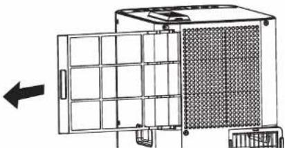
- CLEANING & MAINTENANCE
Before cleaning or maintenance, turn the appliance off and always unplug the appliance.
Cleaning: Wipe with a soft dry cloth. Never wash the air conditioner with water. Never use volatile substance such as gasoline or polishing powder to clean the appliance.
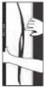
Air filter maintenance: It is necessary to clean the air filter after using it for about 100 hours. Stop the appliance and then pull back the air filter. (fig.2) Use a vaccum cleaner, water or a soft dry cloth to clean the filter, and then reinstall it. Do not use the appliance without the filter.
natural_image
Diagram of a mechanical or industrial device with grid layout and directional arrow (no text or symbols)Fig.2
OPERATING INSTRUCTIONS
The electrical facilities of the room, as well as the installation and use of the appliance must comply with the standards in force in your country.
Before first use, ensure that the voltage, frequency and power of your appliance are suitable for your electrical supply.
Your device must operate with an earthed power socket. It is a class I appliance. Before switching on your appliance, ensure that:
• The appliance is positioned in accordance with the instructions in this manual;
• The air intake and outlet grills are completely unobstructed;
• The appliance is placed on a stable horizontal surface;
Do not place under a clothesline or any other object likely to cause water to fall in the product.
N.B.: You are advised to unplug the appliance when not in use.
INSTALLATION INSTRUCTIONS
text_image
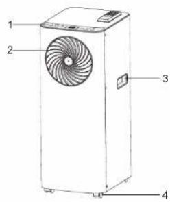
1 2 3 4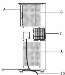
text_image
5 6 7 8 9 10- Control panel
- Air outlet
- Handle hole
- Caster
- Air filter
- Air intake (Evaporator)
- "External" air outlet (air conditioner mode)
- Air intake (Condenser)
- Water outlet drain
- Power supply cord
Note : Please ensure if the water outlet drain is well installed before use.
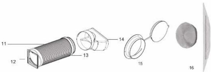
- Exhaust hose
12&13. Exhausted connectors - Exhaust nozzle
- Wall flange accessory and cap
- Window seal kit (included in AU5020F0 only)
text_image
11 12 13 14 15 16EN

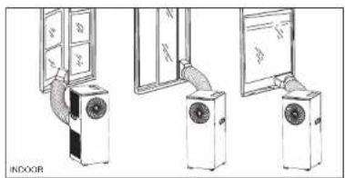
Installation 1 - mobile installation
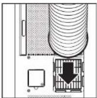
1/ Click the exhausted nozzle (#14) to the exhausted connector
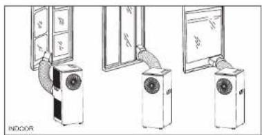
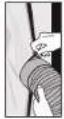
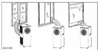
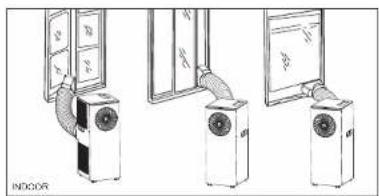
2/ Slide the other exhausted connector (#12) to the air outlet (#7) on the rear of the unit (Fig 3) Extend hose (#11) to desired length and position the exhausted nozzle (#14) through an open window as shown on fig.4.
natural_image
Diagram of a computer tower with ventilation ducts and a directional arrow indicating movement (no text or symbols)Fig. 3
natural_image
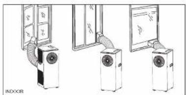
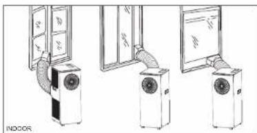
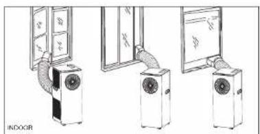
Illustration of indoor air conditioner unit with door and fan assembly (no text or symbols)Fig. 4
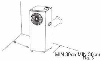
Semi-permanently installation
If required, your appliance can also be installed semi permanently (Fig. 5)
Proceed as follows:
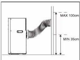
- Drill a hole in an outside wall or through a window pane. Ensure the MIN / MAX dimensions for the hole size and its position are adhered to. (Fig. 6 and 7)
- Fit the wall flange accessory (#15) provided in the hole.
- Insert another end of the hose assembly to the fixture previously fit on the wall a shown in (Fig. 6) When the hose is not in use, place the cap (#15) on connector to cover the hole on the wall.
NOTE: When installing the air conditioner semi permanently, to maintain the balance of air pressure between indoors and outdoors always leave an internal door slightly open.
text_image
MIN 30cmMIN 30cm Fig. 516
text_image
MAX 100cm MIN 35cmFig. 6&7
text_image
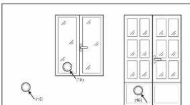
750 750 160HOW TO INSTALL THE WINDOW SEAL KIT
The window seal kit is included in the reference AU5020F0. It can be bought as a Rowenta accessory with reference XD6620F0 (#16). Before installation, check that the adhesive gripping tape do not damage your window.
 | 1. Open the window and clean the surfaces to remove dust and grease on the window frame and casement. Stick the strip to the frame. Do not stick it to the contact surface of the window seal (you must be able to close the window). |
| 3X73 | 2. Stick the strip to the outside or inside of the window casement (handle side) Ensure that the window can be closed. Before sticking together, make sure the sticky surface does not damage the window frame. |
 | 3. Leave the window open. First stick the wide side of the window form (zip closed) from the center to the right and left hand sides or to the top and bottom to the window frame. |
 | 4. Close the window and make sure that it does not clamp the window form. Stick the narrow side of the window form (zip closed) from the center to the right and left hand sides or to the top and bottom to the casement. |
 | 5. Open the window slightly to have the exhaust hose into the window form by using the zipper. |


CONTROL PANEL
text_image
电源 + - (ADC/DJ/F) TIME MODE * * * * * * * * * * * - + * * * * * * - +Power Control (A)
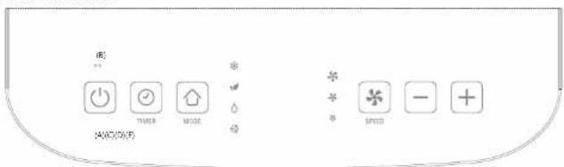
The power control turns the unit on and off. After switching the air conditioner off, you must wait 3 minutes before switching it back on again.
Warning Light "FULL" (B)
Condensed water may accumulate in the unit.
If the internal tank becomes full, the warning light will come on and the unit will stop operating until the unit has been drained (evacuation #9). To drain the unit, refer to storage instructions p.2.
Timer (C)
Auto turn OFF: with the machine in running mode, press the timer button. Then set the desired working time in hours before shut down by pressing the "+" or "-" buttons.
Auto turn ON: With the machine in OFF mode, press the timer button. Then set the desired time delay ON in hours by pressing the "+" or "-" buttons before the unit automatically starts running in the latest used mode.
The time is adjustable between 1 to 24hours
Mode Control (D)
The mode control has four settings. A light indicates which mode is currently being used.
- Cooling mode : During the cooling mode the air is cooled and hot air is expelled through the heat exhaust hose (#12). Adjust fan speed and air temperature to suit your desired comfort level. Use the buttons (-) and (+) to set the desired temperature between 16 and 32^ . After 10 seconds the display will revert to room temperature. Note: the air exchange hoses must vent outside the room when using cooling mode.
- Eco mode ⬆: In this mode, the targeted temperature is automatically set up -3°C vs the room temperature to save energy. The speed is automatically defined. After 3 seconds the display will revert to room temperature.
- Dehumidify mode : Air is dehumidified as it passes through the unit, without being in full cooling mode. In this mode, if temperature is higher than 25^ , fan speed can be adjusted; otherwise, fan speed is fixed to "low". In this mode, do not connect the exhaust hose and let the warm air return to the room. You will need to drain the unit to evacuate the water: refer to storage instructions p.2, for installation.
- Fan Mode ◦: air is circulated throughout the room with no cooling. The air exchange hose does not need to be installed in this mode Adjust fan speed to suit your desired comfort level.
Fan Speed Control (E)
The fan speed control has three settings: High, Medium and Low.
Remote control
The remote control uses 2 x AAA or LR03 1.5V batteries which are not included.
To change the remote's battery, remove the cover on the back of the remote controller and insert batteries with the (+) and (-) poles pointing in the proper direction.
Remove the batteries if the remote control is not used for a month or longer.
Remote control operations are identical to the functions on the control panel. Please take care not to scratch or damage the transmitter (LED) located on the end of the remote control as this will impair its proper operation.
TROUBLESHOOTING
| Trouble Analysis | |
| The appliance does not start - Please wait 3 | minutes and start again,protector device may be preventing unit from working.- The plug is not properly plugged. |
| The appliance stops running during operation - | Set temperature is too high.- Air outlets are blocked by obstacles or hose is obstructed- Air inlets (filter) are blocked by dust |
| The appliance does not run and water full indicator is lit | - Water needs to be drained : please refer to paragraph “control panel – B”- Drainage hose is obstructed or twisted |
| LEDs display “E1” or “E2” | - Please refer to a specific Approved Service Centre. |
SHOULD A PROBLEM ARISE
Never dismantle the appliance yourself because R290 gas requires specific agreement for repairing. A poorly repaired appliance may be dangerous for the user.
Do not use the appliance and contact a specific Approved Service Centre if:
• The appliance has broken.
- Unit or its power cord is damaged,
- If your appliance does not work properly.
You can find a list of specific Approved Service Centres on Rowenta website.
HELP PROTECT THE ENVIRONMENT!

Your appliance contains valuable materials which can be recovered or recycled.
Leave it at a waste collection point or an approved service centre so that it can be disposed of correctly.
Do not throw away the batteries with your household waste: instead, bring them to anyone of the special battery collection points.
These instructions can also be found on our internet site www.rowenta.com

natural_image
Technical line drawing of a mechanical assembly with a meshed component and base (no text or symbols)Abb. 1
natural_image
Diagram of a mechanical device with a grid-patterned panel and directional arrow (no text or symbols)Abb. 2
BEDIENUNGSANLEITUNG
Installation 1 – mobile Installation
natural_image
Diagram of a server rack with ventilation ducts and a directional arrow indicating airflow or movement (no text or symbols)Abb. 3
natural_image
Illustration of indoor air conditioner unit with two doors and a door, showing airflow direction (no text or symbols)Abb. 4
Halbpermanente Installation
natural_image
Simple line drawing of a mechanical or electrical component with no text, numbers, or symbolsFig. 1
- LIMPIEZA Y MANTENIMIENTO
natural_image
Diagram of a modular device with a grid panel and mesh structure, showing an open panel and a directional arrow (no text or symbols)Fig. 2.
natural_image
Top-down schematic of a device layout with ventilation ducts, control panel, and directional arrow (no text or symbols)Fig. 3
natural_image
Illustration of indoor air conditioner unit with door and ceiling-mounted fans (no text or symbols)Fig. 4
text_image
MIN 30cm MIN 30cm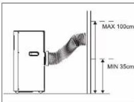
text_image
MAX 100cm MIN 35cm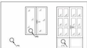
text_image
(16) (16)Fig. 6 y 7
natural_image
Technical line drawing of a mechanical assembly with no visible text or symbolsFig. 1
natural_image
Diagram of a modular device with a grid panel and side-mounted components, showing an arrow pointing left (no text or symbols present)Fig. 2.
natural_image
Top-down schematic of a room layout with ceiling, door, and storage unit (no text or symbols)Fig. 3
natural_image
Illustration of indoor air conditioner unit with three different cooling methods (no text or symbols)Fig. 4
natural_image
Technical line drawing of a mechanical device with a mesh grille and base mount (no text or symbols)Fig. 1
natural_image
Diagram of a modular device with a grid panel and directional arrow (no text or symbols)Fig. 2.
text_image
Technical diagram of a mechanical component with numbered parts, including a cylindrical housing and multiple lenses.51


natural_image
Top-down schematic of a room layout with ceiling, wall, and floor indicators (no text or symbols)Fig. 3
natural_image
Illustration of indoor air conditioner unit with cooling fan and door, showing three steps (no text or symbols)Fig. 4
text_image
MIN 30cm MIN 30cm52

text_image
MAX 100cm MIN 35cm
text_image
(16) (16)Fig. 6 e 7
natural_image
Technical line drawing of a mechanical assembly with a meshed component and base (no text or symbols)Fig. 1
- REINIGING EN ONDERHOUD
natural_image
Diagram of a modular device with a grid panel and side-mounted components, showing an arrow pointing to the left side (no text or symbols present)Fig. 2.
BEDIENINGSINSTRUCTIES
natural_image
Architectural floor plan showing room layout with ceiling, door, and wall-mounted equipment (no text or labels)Fig. 3
natural_image
Illustration of indoor air conditioners with ventilation ducts, no text or symbols presentFig. 4