
CM-C54T - Loudspeaker PIONEER - Free user manual and instructions
Find the device manual for free CM-C54T PIONEER in PDF.
| Product Type | Passive coaxial wideband in-ceiling speaker |
| Brand | Pioneer |
| Model | CM-C54T |
| Frequency Response | 85 Hz – 20 kHz |
| Sensitivity (1 W/1 m) | 86 dB |
| Nominal Impedance | 16 Ω |
| Power Handling (RMS/Program) | 30 W / 60 W |
| Transformer Power 70 V | 30 W / 15 W / 7.5 W / 3.7 W |
| Transformer Power 100 V | 30 W / 15 W / 7.5 W |
| Dispersion | 120° |
| Max SPL | 100 dB |
| Woofer | 4-inch (102 mm) cone |
| Tweeter | 3/4-inch (20 mm) dome tweeter |
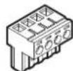
| Connector | 4-pin Euroblock (input +/-, loop +/-) |
| Dimensions (Diameter × Height) | 240 × 210 mm |
| Weight (1 piece) | 2.6 kg |
| Ceiling Cutout Size | 187.5 mm |
| Ceiling Thickness Compatible | 6 – 20 mm |
| Panel Material | Steel grille, PC-ABS frame (UL94-V0) |
| Enclosure Material | Steel backcan, PC-ABS baffle (UL94-V0) |
| Available Color | White (CM-C54T-W) or Black (CM-C54T-K) |
| Operating Temperature | 5 °C to 35 °C |
| Included Accessories | Panels ×2, reinforcement plates ×4, C-ring screws ×4, cutout template ×1, Euroblock connectors ×2, manual ×2 |
| Warranty (USA/Canada) | 5 years parts and labor |
Frequently Asked Questions - CM-C54T PIONEER
User questions about CM-C54T PIONEER
0 question about this device. Answer the ones you know or ask your own.
Ask a new question about this device
Download the instructions for your Loudspeaker in PDF format for free! Find your manual CM-C54T - PIONEER and take your electronic device back in hand. On this page are published all the documents necessary for the use of your device. CM-C54T by PIONEER.
USER MANUAL CM-C54T PIONEER
For installation and other support information, visit the above site.
Installation and Instruction Manual
Thank you for purchasing this product. Carefully read this installation and user's manual before using the product. Pay particular attention to the content described in "Read Before Use". Store this installation and user's manual in a safe place so that it can be referred to at any time.
Read Before Use (Important)
[For American Users
THE MODEL NUMBER AND SERIAL NUMBER OF THIS EQUIPMENT ARE ON THE REAR OR BOTTOM. RECORD THESE NUMBERS ON YOUR ENCLOSED WARRANTY CARD AND KEEP IN A SAFE PLACE FOR FUTURE REFERENCE.
D36-AP9-1_A1_En
[For American Users and Canadian Users] The Safety of Your Ears is in Your Hands
Get the most out of your equipment by playing it at a safe level – a level that lets the sound come through clearly without annoying blaring or distortion and, most importantly, without affecting your sensitive hearing. Sound can be deceiving. Over time, your hearing "comfort level" adapts to higher volumes of sound, so what sounds "normal" can actually be loud and harmful to your hearing. Guard against this by setting your equipment at a safe level BEFORE your hearing adapts.
ESTABLISH A SAFE LEVEL:
- Set your volume control at a low setting.
- Slowly increase the sound until you can hear it comfortably and clearly, without distortion.
- Once you have established a comfortable sound level, set the dial and leave it there.
BE SURE TO OBSERVE THE FOLLOWING GUIDELINES:
- Do not turn up the volume so high that you can't hear what's around you.
- Use caution or temporarily discontinue use in potentially hazardous situations.
- Do not use headphones while operating a motorized vehicle; the use of headphones may create a traffic hazard and is illegal in many areas.
S001a_A1_En
[For European Users]
![PIONEER CM-C54T - [For European Users] - 1](/content/2026/04/648310/images/2cb0bcd1f9016746aeb9515043c9ae4e8209cdb5698660ff74266480e3f0014b.jpg)
If you want to dispose of this product, do not mix it with general household waste. There is a separate collection system for used electronic products in accordance with legislation that requires proper treatment, recovery and recycling.
Private households in the member states of the EU, in Switzerland and Norway may return their used electronic products free of charge to designated collection facilities or to a retailer (if you purchase a similar new one).
For countries not mentioned above, please contact your local authorities for the correct method of disposal.
By doing so you will ensure that your disposed product undergoes the necessary treatment, recovery and recycling and thus prevent potential negative effects on the environment and human health.
K058b_B_En
![PIONEER CM-C54T - [For European Users] - 2](/content/2026/04/648310/images/062e1ad10f311919f1757c132423cee855027fe074b150a2278910bc7a9361cb.jpg)
WARNING
Installation
This loudspeaker should be installed by a professional installer.
There is a risk the loudspeaker may fall. Ask a professional installer that possesses sufficient skills and experience to install the loudspeaker. Two or more workers are also recommended for installation.
AlphaTheta Corporation bears no responsibility for accidents and damage resulting from deficient installation or mounting, misuse, modifications, and/or natural disasters.
When the loudspeaker is installed by suspending it from the ceiling or another surface, first check the strength of the installation location and the installation method, and then implement safety measures.
Always implement redundant safety measures, such as by using a fall prevention wire.
Use only the accessories included with the loudspeaker. Do not use the accessories for any other purpose.
There is a risk of accident and damage such as due to the loudspeaker falling.
Only the workers installing the loudspeaker should be near it during installation.
There is a risk of injury if parts fall.
Usage Environment
Do not use the loudspeaker in an environment where water will get inside it or where it will become wet.
Be particularly careful when using the loudspeaker near rain, snow, seashores, waterfronts, bathrooms, and shower rooms. There is a risk of fire and electric shock.
Do not install the loudspeaker in the following environments.
- Poorly ventilated locations with high humidity or a large amount of dust. - Locations with a large amount of oily smoke, such as inside kitchens or factories
• Unstable locations, such as those exposed to vibrations or those that are sloped.
- Locations where flammable materials are used, such as alcohols and aerosol insecticides.
- Locations affected by heat generation, such as near light fixtures or heaters.
- Locations exposed to direct sunlight and locations easily affected by the outdoor air.
There is a risk of deformation or discoloration of the enclosure and failure of the loudspeaker, which may result in fire or the loudspeaker falling in a worst case scenario.
Use the loudspeaker in the following environment.
Temperature: 5°C to 35°C
Humidity: 35% to 65% (winter) / 40% to 70% (summer)
Usage Methods
Do not insert metallic or flammable objects into the holes on the front of the loudspeaker, and do not allow those objects to fall into the holes.
There is a risk of fire or electric shock if metallic or flammable objects get inside the loudspeaker. Be particularly careful in homes with children.
Do not place small parts within reach of young children.
Promptly consult with a physician if a small part is accidentally swallowed.
To prevent a fire hazard, do not place any naked flame sources (such as a lighted candle) on the equipment.
Actions If Problems Occur
Immediately stop using the loudspeaker if a problem occurs.
If a problem occurs, such as smoke, an unusual odor, or the loudspeaker is damaged by ingress of water or a foreign object, immediately turn off the power to the amplifier that is used, and then request repair. There is a risk of fire and electric shock if the loudspeaker is used when there is a problem.

CAUTION
Installation
When connecting the loudspeaker to other equipment, turn off the power to each piece of equipment.
Carefully read the user's manual for each piece of equipment, and connect the equipment according to the description in the manual. In addition, use the specified cords to connect the equipment. There is a risk of electric shock.
Check the stability of the loudspeaker after mounting it to the ceiling. Inspect the loudspeaker immediately after mounting it. In addition, check the stability of the loudspeaker regularly.
Do not install the loudspeaker outdoors.
This loudspeaker is for indoor use only.
Be careful not to crush your fingers in the spring-loaded ceiling fastening tabs.
There is a risk of injury.
Usage Methods
Do not use the loudspeaker in the following states.
Do not exceed the permissible input.
- If greatly increasing high pitched sounds with a graphic equalizer, do not increase the volume too much.
- Do not force the loudspeaker to produce loud sounds with a low output power amplifier.
- Do not use the loudspeaker for a long period of time when the sound is distorted.
The loudspeaker may be damaged, resulting in heat generation and fire.
Turn the volume all the way down before turning on the power and changing the connection.
There is a risk of hearing loss and other problems if the loudspeaker suddenly produces a loud sound.
Do not listen to the loudspeaker at high volumes for a long period of time.
There is a risk of hearing loss.
To prevent the risk of electric shock, do not remove cover (or back). No user-serviceable parts inside. Refer servicing to qualified service personnel.
Checking the Accessories
- Panel ×2
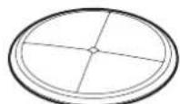
- Tile bridge ×4

C-ring ×2
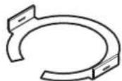
• C-ring fastening screw ×4

• Template for cutting the ceiling hole ×1
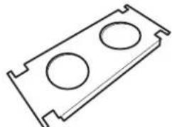
- 4-pin Euroblock connector ×2 *Attached to the speaker's terminal
• Installation and Operating Instructions (this document) ×2

* The speaker wire and fall prevention wire are not included.
Installation and Connections

CAUTION
• Do not mount the loudspeaker on a sloped ceiling.
• Largest supported wire size: 12 AWG
• Smallest supported wire size: 22 AWG
- Confirm that the ceiling to which the loudspeaker will be installed has sufficient strength and the necessary thickness.
Even if the thickness is adequate, you must separately confirm the load bearing capacity of the ceiling board. Supported ceiling thickness: 6 to 20 mm (0.24 to 0.79 inches)
- The C-rings are not for reinforcement. They are safety mechanisms. If the loudspeaker is mounted to a weak ceiling, the ceiling may sag after a long period of time.
- Reinforce the ceiling as appropriate because loudspeaker output may cause the ceiling to resonate and impact sound quality.
- Be careful not to touch the diaphragm of the loudspeaker.
Cutting the Hole in the Ceiling
- Place the included template on the ceiling and draw the line for the hole. Or use a hole cutter and cut the mounting hole in the ceiling. Hole dimensions CM-C56T: φ 226 mm (8.90 inches) CM-C54T: φ 187.5 mm (7.38 inches)

CAUTION
Wear safety goggles to prevent dust and debris from getting in your eyes.
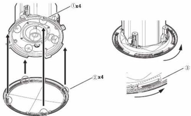
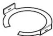
Installing the Tile Bridges and C-Ring
1 Insert the two tile bridges ① into the ceiling ② and place them as shown in the diagram.
2 Align the C-ring ③ with the hole in the ceiling ② as shown in the diagram and fit it on the tile bridges. Next, fasten the C-ring to the tile bridges with the screws ④.
Tightening torque: 1 N·m

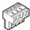
Connecting the Loudspeaker
This section describes how to connect the loudspeaker to the power amplifier and other speakers. The connector for this loudspeaker consists of four terminals. Terminal 1 is the "+" loop-through terminal, terminal 2 is "+" , terminal 3 is "-" , and terminal 4 is the "-" loop-through terminal. Terminals 1 and 2 and terminals 3 and 4 are connected inside the loudspeaker.
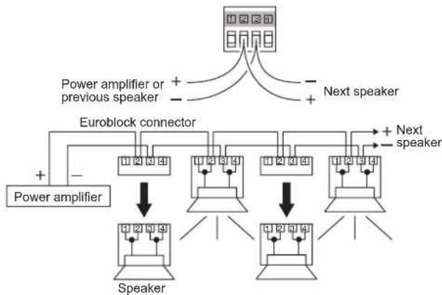
Parallel connection
This connection method enables other speakers to work normally as long as their wires are connected to the terminals even if one speaker has a problem. Connect the wires for the next speaker to the same terminals that fasten the previous speaker wires as shown in the diagram below.
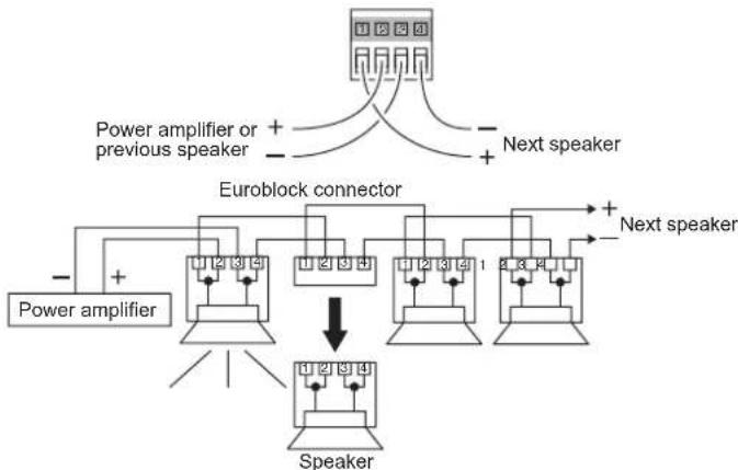
Loop-through connection
This connection method enables easily identifying a speaker that has a problem. If the Euroblock connector is disconnected from a speaker, the subsequent speakers do not work anymore. Connect the previous speaker wires to "+" (terminal 2) and "-" (terminal 3) of IN and the next speaker wires to "+" (terminal 1) and "-" (terminal 4) of the loop-through connection.
1 Loosen the screw ① and remove the connector cover ②. Disconnect the Euroblock connector ③ a from the rear connector.
2 Strip about 7 mm (0.28 inches) of the insulation at the tips of the speaker wire. Loosen the screws ④ and ⑤, open the cord bushing ⑥, and pass the speaker wire through the cord bushing.
3 Insert the conductors of the speaker wire into the terminals on the Euroblock connector, and then fasten the conductors by tightening the screws ③b. Next, connect the Euroblock connector ③a to the rear connector.

CAUTION
Take care to tightly twist the conductors of the speaker wire and ensure the conductors do not touch each other. There is a risk of damage to the loudspeaker and power amplifier.
4 Tighten the screw ① to fasten the connector cover ②.
5 Tighten screw ④ and screw ⑤ in that order so that the speaker wire fits into the groove ⑦ of the cord bushing ⑥.
![graph TD A["①"] --> B["②"] B --> C["③a"] C --> D["④x2"] D --> E["⑤x2"] E --> F["⑥x2"] F --> G["③b"] style A fill:#f9f,stroke:#333 style B fill:#ccf,stroke:#333 style C fill:#cfc,stroke:#333 style D fill:#fcc,stroke:#333 style E fill:#cff,stroke:#333 style F fill:#ffc,stroke:#333 style G fill:#cfc,st…](/content/2026/04/648310/images/9c325bac82c08eb1ac23366c40aae5d6a091b0cd0d0707de9a576d306b9cfee4.jpg)

CAUTION
Take care so that the flat portion of the cord bushing ⑥ does not crush the speaker wire.
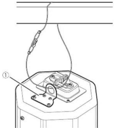
Attaching the Fall Prevention Wire
- Attach the fall prevention wire (procured by the installer) to the bracket ①, and then secure the other end to the frame of the ceiling.

CAUTION
Always implement fall prevention measures for the loudspeaker. Use a fall prevention wire of a suitable length and strength that takes into consideration the weight of the loudspeaker and the state of the installation. If the wire is too long, the loudspeaker may hit someone if it falls.
Fastening the Loudspeaker to the Ceiling
1 Confirm that the ceiling fastening tabs ① are in the stored position. If the ceiling fastening tabs are not in the stored position, push the fastening screw ② on the front of the loudspeaker all the way in with a Phillips screwdriver, and then turn the screw counterclockwise to store the ceiling fastening tabs.
2 Push the loudspeaker up into the hole until the frame③ around the front of the loudspeaker makes contact with the ceiling.
3 Push in the fastening screw② with a Phillips screwdriver and turn the screw clockwise to move the four ceiling fastening tabs ① and fasten the loudspeaker to the ceiling board.
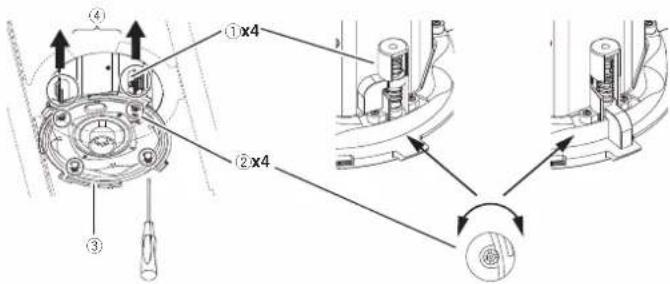

CAUTION
- Confirm that the ceiling fastening tabs ① have extended out from the loudspeaker and that the loudspeaker is securely fastened to the ceiling board. If the loudspeaker is not sufficiently fastened to the ceiling board, it may fall from the ceiling.
- Turn only fastening screw. Do not turn any other screws. There is a risk of damage and the loudspeaker falling.
- Do not fasten the ceiling fastening tabs 1 at the cut for the C-ring 4
Take care so that the speaker wire is not crushed by the frame③ around the front of the loudspeaker and the ceiling fastening tabs ①.
Setting the Input Selection
1 Set the input selection switch on the front of the loudspeaker to the △ symbol.
2 The illustration shows a 60 W setting when the CM-C56T is connected to a 100 V line and a 30 W setting when connected to a 70 V line.
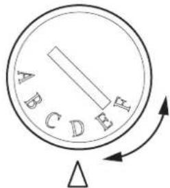
| CM-C56T CM-C54T | ||||||
| 100 V 70 V | 100 V 70 V | |||||
| A 16Ω | 60 W | 16Ω | 30 W | |||
| B OFF | ||||||
| C --- | 60 W | --- | 30 W | |||
| D 60 | W | 30 W | 30 W | 15 W | ||
| E 30 | W | 15 W | 15 W | 7.5 W | ||
| F 15 | W | 7.5 W | 7.5 W | 3.7 W | ||

CAUTION
- Use position A only when the loudspeaker is used with a low impedance amplifier. The loudspeaker and power amplifier may be damaged if the setting is wrong.
- Turn off the power to the power amplifier before working.
Attaching the Panel
1 Fit the panel onto the loudspeaker by aligning the △ symbol ① on the front of the loudspeaker with the position of the △ symbol ② on the back of the panel, and then push it and turn it clockwise.

CAUTION
The panel may fall off if it is not sufficiently fit onto the loudspeaker. Firmly turn the panel until it bites into the serration ③.
2 Fasten the panel in the area where the serration ③ makes a noise
3 To remove the panel, twist it counterclockwise.
© 2020 AlphaTheta Corporation. All rights reserved.
AlphaTheta Music Americas, Inc.
LIMITED WARRANTY
WARRANTY VALID ONLY IN THE U.S.A. AND CANADA
FIVE YEARS LIMITED WARRANTY
AlphaTheta Music Americas, Inc. (COMPANY) warrants that Pioneer DJ/Pioneer branded products distributed by COMPANY in the U.S.A. and Canada that fail to function properly under normal use and conditions due to a manufacturing defect when installed and operated according to the owner's manual enclosed with the unit, and any officially published guidelines such as technical specifications or service communications, will be repaired or replaced with a unit of comparable value, at the option of COMPANY, without charge to you for parts or actual repair work. Parts supplied under this warranty may be new or rebuilt at the option of COMPANY.
THIS WARRANTY IS VALID ONLY IN THE COUNTRY OF PURCHASE. THIS LIMITED WARRANTY APPLIES TO THE ORIGINAL OR ANY SUBSEQUENT OWNER OF THIS PRODUCT DURING THE WARRANTY PERIOD PROVIDED THE PRODUCT WAS PURCHASED FROM AN AUTHORIZED COMPANY DISTRIBUTOR/DEALER IN THE U.S.A. OR CANADA. YOU WILL BE REQUIRED TO PROVIDE A SALES RECEIPT OR OTHER VALID PROOF OF PURCHASE SHOWING THE DATE OF ORIGINAL PURCHASE OR, IF RENTED, YOUR RENTAL CONTRACT SHOWING THE PLACE AND DATE OF FIRST RENTAL. IN THE EVENT SERVICE IS REQUIRED, THE PRODUCT MUST BE DELIVERED WITHIN THE WARRANTY PERIOD, TRANSPORTATION PREPAID, ONLY FROM WITHIN THE U.S.A. OR CANADA, AS APPLICABLE. AS EXPLAINED IN THIS DOCUMENT. YOU WILL BE RESPONSIBLE FOR REMOVAL AND INSTALLATION OF THE PRODUCT. COMPANY WILL PAY TO RETURN THE REPAIRED OR REPLACEMENT PRODUCT TO YOU WITHIN THE U.S.A. OR CANADA, AS APPLICABLE.
PRODUCT WARRANTY PERIOD
Parts Labor
Audio and Video
5 Years 5 Years
The warranty period for retail customers who rent the product commences upon the date product is first put into use (a) during the rental period or (b) retail sale, whichever occurs first.
WHAT IS NOT COVERED
IF THIS PRODUCT WAS PURCHASED FROM AN UNAUTHORIZED DISTRIBUTOR, THERE ARE NO WARRANTIES, EXPRESS OR IMPLIED, INCLUDING THE IMPLIED WARRANTY OF MERCHANTABILITY AND THE IMPLIED WARRANTY OF FITNESS FOR A PARTICULAR PURPOSE AND THIS PRODUCT IS SOLD STRICTLY "AS IS" AND "WITH ALL FAULTS".
COMPANY SHALL NOT BE LIABLE FOR ANY CONSEQUENTIAL AND/OR INCIDENTAL DAMAGES, INCLUDING WITHOUT LIMITATION LOSS OF USE, LOSS OF PROFITS OR LOSS OF WAGES, TO THE GREATEST EXTENT ALLOWED BY APPLICABLE LAW.
THIS WARRANTY DOES NOT APPLY IF THE PRODUCT HAS BEEN SUBJECTED TO POWER IN EXCESS OF ITS PUBLISHED POWER RATING.
THIS WARRANTY DOES NOT COVER THE CABINET OR ANY APPEARANCE ITEM, USER ATTACHED ANTENNA, ANY DAMAGE TO RECORDS OR RECORDING TAPES OR DISCS, ANY DAMAGE TO THE PRODUCT RESULTING FROM ALTERATIONS, MODIFICATIONS NOT AUTHORIZED IN WRITING BY COMPANY, ACCIDENT, MISUSE OR ABUSE, DAMAGE DUE TO LIGHTNING OR TO POWER SURGES, SUBSEQUENT DAMAGE FROM LEAKING, DAMAGE FROM INOPERATIVE BATTERIES, OR THE USE OF BATTERIES NOT CONFORMING TO THOSE SPECIFIED IN THE OWNER'S MANUAL.
THIS WARRANTY DOES NOT COVER THE COST OF PARTS OR LABOR WHICH WOULD BE OTHERWISE PROVIDED WITHOUT CHARGE UNDER THIS WARRANTY OBTAINED FROM ANY SOURCE OTHER THAN A COMPANY AUTHORIZED SERVICE COMPANY OR OTHER DESIGNATED LOCATION. THIS WARRANTY DOES NOT COVER DEFECTS OR DAMAGE CAUSED BY THE USE OF UNAUTHORIZED PARTS OR LABOR OR FROM IMPROPER MAINTENANCE.
ALTERED, DEFACED, OR REMOVED SERIAL NUMBERS VOID THIS ENTIRE WARRANTY
THIS WARRANTY DOES NOT COVER DAMAGE CAUSED BY TAMPERING, ABUSE, OR NEGLECT OF THE PRODUCT, OR BY PARTS NOT PROVIDED BY COMPANY. COMPANY AND ITS SERVICE AND REPAIR FACILITIES ARE NOT RESPONSIBLE FOR DAMAGE OR LOSS OF ELECTRONIC INFORMATION OR DATA STORED ON ANY RETURNED PRODUCT.
NO OTHER WARRANTIES
COMPANY LIMITS ITS OBLIGATIONS UNDER ANY IMPLIED WARRANTIES INCLUDING, BUT NOT LIMITED TO, THE IMPLIED WARRANTIES OF MERCHANTABILITY AND FITNESS FOR A PARTICULAR PURPOSE, TO A PERIOD NOT TO EXCEED THE WARRANTY PERIOD. NO WARRANTIES SHALL APPLY AFTER THE WARRANTY PERIOD. SOME STATES DO NOT ALLOW LIMITATIONS ON HOW LONG AN IMPLIED WARRANTY LASTS AND SOME STATES DO NOT ALLOW THE EXCLUSIONS OR LIMITATIONS OF INCIDENTAL OR CONSEQUENTIAL DAMAGES, SO THE ABOVE LIMITATIONS OR EXCLUSIONS MAY NOT APPLY TO YOU. THIS WARRANTY GIVES YOU SPECIFIC LEGAL RIGHTS AND YOU MAY HAVE OTHER RIGHTS WHICH MAY VARY FROM STATE TO STATE.
NO DEALER, DISTRIBUTOR, OR EMPLOYEE OF COMPANY IS AUTHORIZED TO MAKE ANY MODIFICATION, EXTENSION, OR MODIFICATION OF THIS WARRANTY.
If any term of this warranty is held to be illegal or unenforceable, the legality or enforceability of the remaining terms shall not be affected or impaired.
TO OBTAIN SERVICE
COMPANY has appointed a number of Authorized Service Companies throughout the U.S.A. and Canada should your product require service. To receive warranty service you need to present your sales receipt or, if rented, your rental contract showing place and date of original owner's transaction. If shipping the unit you will need to package it carefully and send it, transportation prepaid by a traceable, insured method, to an Authorized Service Company. Package the product using adequate padding material to prevent damage in transit. The original container is ideal for this purpose. Include your name, address and telephone number where you can be reached during business hours.
On all complaints and concerns in the U.S.A. and Canada call Customer Support at 1-844-784-0000.
For hook-up and operation of your unit or to locate an
Authorized Service Company, please call or visit:
AlphaTheta Music Americas, Inc.
1-844-784-0000
pioneerdj.com
DISPUTE RESOLUTION
Following our response to any initial request to Customer Support, should a dispute arise between you and COMPANY, COMPANY makes available its Complaint Resolution Program to resolve the dispute. The Complaint Resolution Program is available to you without charge. You are required to use the Complaint Resolution Program before you exercise any rights under, or seek any remedies, created by Title I of the Magnuson-Moss Warranty-Federal Trade Commission Improvement Act, 15 U.S.C. 2301 et seq. To use the Complaint Resolution Program call 1-844-784-0000 and explain to the customer service representative the problem you are experiencing, steps you have taken to have the product repaired during the warranty period and the name of the authorized Distributor/Dealer from whom the Pioneer DJ/Pioneer branded product was purchased. After the complaint has been explained to the representative, a resolution number will be issued. Within 40 days of receiving your complaint, COMPANY will investigate the dispute and will either: (1) respond to your complaint in writing informing you what action COMPANY will take, and in what time period, to resolve the dispute; or (2) respond to your complaint in writing informing you why it will not take any action.
RECORD THE PLACE AND DATE OF PURCHASE FOR FUTURE REFERENCE
Model No.
Serial No.
Purchase Date
Purchased From
KEEP THIS INFORMATION AND YOUR SALES RECEIPT IN A SAFE PLACE
UCP1219-D5
Introduction
- Anneau en C ×2


ATTENTION

ATTENTION

ATTENTION

ОСТОРОЖНО

ОСТОРОЖНО
- Anel C-Ring ×2

- Conector Euroblock de 4 pinos ×2 *Aplicado ao terminal do altifalante
Ligar o altifalante

CUIDADO

CUIDADO

CUIDADO
- C リング × 2
- Cリング固定用ネジ × 4

- 天井穴開け用テンプレート × 1

接続

注意

注意
必ず落下防止対策を施してください。

注意
| CM-C56T CM-C54T | ||||||||
| 100 V | 70 V | 100 V | 70 V | |||||
| A | 16Ω | 60W | 16Ω | 30W | ||||
| B | OFF | |||||||
| C | --- | 60W | --- | 30W | ||||
| D | 60W | 30W | 30W | 15W | ||||
| E | 30W | 15W | 15W | 7.5W | ||||
| F | 15W | 7.5W | 7.5W | 3.7W | ||||

注意
This warranty is valid only in Japan.
*1 Calculated from the power handling and sensitivity
*2 Pink noise band limited over the specified frequency range by UL testing condition
Spécifications
(Unit : mm (inches))
© 2020 AlphaTheta Corporation. All rights reserved.
AlphaTheta EMEA Limited
Artemis Building, Odyssey Business Park, West End Road, South Ruislip, Middlesex, HA4 6QE, U.K. TEL: +44-203-7617-220
AlphaTheta Music Americas, Inc.
2050 W. 190th Street, Suite 109, Torrance, CA 90504, U.S.A. TEL: +1 (424) 488-0480
Сделано в Китае
Printed in China/Imprimé en Chine
AT_001_all_01
- READ BEFORE USE (IMPORTANT)
- [FOR AMERICAN USERS
- [FOR AMERICAN USERS AND CANADIAN USERS] THE SAFETY OF YOUR EARS IS IN YOUR HANDS
- ESTABLISH A SAFE LEVEL
- BE SURE TO OBSERVE THE FOLLOWING GUIDELINES
- [FOR EUROPEAN USERS]
- WARNING
- INSTALLATION
- USAGE ENVIRONMENT
- USAGE METHODS
- ACTIONS IF PROBLEMS OCCUR
- CAUTION
- CHECKING THE ACCESSORIES
- INSTALLATION AND CONNECTIONS
- CUTTING THE HOLE IN THE CEILING
- INSTALLING THE TILE BRIDGES AND C-RING
- CONNECTING THE LOUDSPEAKER
- PARALLEL CONNECTION
- LOOP-THROUGH CONNECTION
- ATTACHING THE FALL PREVENTION WIRE
- FASTENING THE LOUDSPEAKER TO THE CEILING
- SETTING THE INPUT SELECTION
- ATTACHING THE PANEL
- ALPHATHETA MUSIC AMERICAS, INC
- LIMITED WARRANTY
- WARRANTY VALID ONLY IN THE U.S.A. AND CANADA
- FIVE YEARS LIMITED WARRANTY
- PRODUCT WARRANTY PERIOD
- WHAT IS NOT COVERED
- NO OTHER WARRANTIES
- TO OBTAIN SERVICE
- DISPUTE RESOLUTION
- RECORD THE PLACE AND DATE OF PURCHASE FOR FUTURE REFERENCE
- INTRODUCTION
- ATTENTION
- ОСТОРОЖНО
- LIGAR O ALTIFALANTE
- CUIDADO
- 接続
- 注意
- ALPHATHETA EMEA LIMITED
Brand : PIONEER
Model : CM-C54T
Category : Loudspeaker