DES 2427 - Boiler DIMPLEX - Free user manual and instructions
Find the device manual for free DES 2427 DIMPLEX in PDF.
| Product Type | Electronically controlled instantaneous water heater |
| Brand | Dimplex |
| Model | DES 2427 |
| Rated Power | 24 / 27 kW (selectable) |
| Rated Voltage | 400 V three-phase |
| Fuse Protection | 40 A |
| Minimum Cable Cross-Section | 6 mm² |
| Hot Water Flow Rate (ΔT 30°C, without limiter) | 13.0 / 14.6 L/min |
| Hot Water Flow Rate (ΔT 30°C, with limiter) | 9.3 L/min |
| Activation Flow Rate | 2.5 L/min |
| Activation Flow Pressure | 0.009 MPa (0.09 bar) |
| Minimum Specific Water Resistance | 1300 Ωcm |
| Rated Pressure | 1.0 MPa (10 bar) |
| Maximum Inlet Temperature | 55 °C |
| Energy Efficiency Class | A |
| Load Profile | S |
| Annual Electricity Consumption | 479 kWh |
| Sound Power Level | 15 dB |
| Hot Water Preparation Energy Efficiency | 38.5 % |
| Protection Class | I (mandatory earth connection) |
| Installation Type | Wall-mounted, closed circuit (pressure-resistant) |
| Electrical Connection | All-pole disconnection device (min. 3 mm contact opening) |
| Maintenance | Clean with a soft cloth, no aggressive detergents or steam cleaners |
| Special Accessories | Plaster mounting kit, load shedding relay BZ 45L21, tubular assembly for under-sink |
Frequently Asked Questions - DES 2427 DIMPLEX
User questions about DES 2427 DIMPLEX
0 question about this device. Answer the ones you know or ask your own.
Ask a new question about this device
Download the instructions for your Boiler in PDF format for free! Find your manual DES 2427 - DIMPLEX and take your electronic device back in hand. On this page are published all the documents necessary for the use of your device. DES 2427 by DIMPLEX.
USER MANUAL DES 2427 DIMPLEX
natural_image
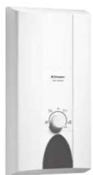
White industrial water heater unit with 'ICDimplex Twin-power' label and control knob (no additional text or symbols)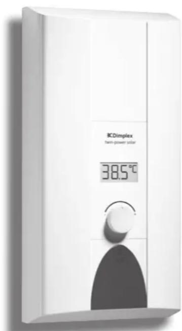
text_image
BCDimplex twin-power solar 38.5°CDimplex
Montageanweisung
Installation Instructions
Electronically-regulated Continuous-flow heater
This appliance is intended for domestic use or for household-based, non-commercial applications. Household-based applications include, e.g. usage in employees catering facilities for shops, offices, agricultural and other commercial operations, as well as usage by guests of guest houses, small hotels and similar residential establishments.
Safety information
Please read this installation instruction manual carefully, then act accor dingly! Store for future reference. These installation instructions must be included when transferring this appliance to a new owner.
The appliance may only be connected and put into operation by a qualified professional.
- Install and operate the appliance as described in the text and illustrations. We do not accept liability for damage resulting from failure to heed these instructions.
The supplied water connection nozzles must be used and installed as shown in the supplementary sheets. Make sure that a check valve is installed in the cold water supply line.
This appliance is intended for use up to an altitude of 2000 m above sea level.
The appliance may only be installed and stored in a frost-free room (due to residual water).
Risk of electric shock! Switch off the mains voltage supply immediately if a fault occurs. Disconnect the power supply before opening the appliance. Immediately shut off the cold water supply to the appliance should it leak.
The statutory regulations of the respective country, as well as those of the local electricity and water suppliers, must be adhered to.
The continuous-flow heater is a Class I appliance and must be connected to the protective earth.
■ Caution: Earthed water pipes may give the appearance of a connected protective earth.
The appliance must be permanently connected to installed pipes. The conductor cross-section must comply with the installed appliance power.
To guarantee compliance to relevant safety regulations, an all-pole separator must be fitted during installation. The contact opening must be at least 3 mm.
The continuous-flow heater is only suitable for closed (pressurised) operation.
The tap and outlet fittings must be approved for operation with closed (pressurised) continuous-flow heater systems.
The continuous-flow heater can be operated with cold or pre-warmed water (only applies to DES). Observe the technical data and the special accessories for this purpose.
The water's specific electrical resistivity must not be less than 1 300 Ωcm. Ask the local water utility company regarding the electrical resistivity of the water.
The continuous-flow heater is suitable for connection to DVGW-tested plastic pipes.
■ Disconnect the electrical connection cable from the supply and shut off the water supply before connecting the appliance!
■ Connect the water supply and then connect the electrical supply.
Only make the openings which are required for installation on the rear of the appliance. If the appliance is reinstalled, the unused openings must be provided with watertight sealing.
- Do not touch electrically live parts after installation.
- Do not use aggressive or abrasive cleaning detergents!
- Do not use a steam cleaner.
Congratulations on purchasing this Dimplex appliance. You have acquired a top-quality product, which will give you a lot of enjoyment.
Installation instructions
These installation instructions apply to various continuous-flow heater appliance models. Therefore the illustrations may deviate from the device you bought.
- Install the appliance as shown in the illustrations. The illustrations can be found in the centre of the instruction manual. Observe the instructions in the text.
Installation
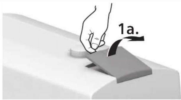
1. Unpacking/Removing the cover
- Unpack the appliance and check for transport damage. If any components are damaged, then do not connect the appliance.
Check that your appliance contains all components included in the scope of delivery: appliance, installation set with supplementary sheets, installation instructions, operating instructions. - Please dispose of the packaging and the old appliance in an environmentally-friendly manner.
- When removing the cover, please note the following: The cover is fastened by a central closure behind the serviceflap.
II. Preparations for installation
Important: Only use the supplied installation set.
The supplied water connection nozzles must be installed!
Shut off water supply. The electrical connection (connection cable) must be disconnected from the power supply. Unscrew the fuse or switch off the circuit breaker.
- Install the water connection nozzles according to the instructions on the supplementary sheet.
The electrical connection cable can either be guided in at the top (X) or bottom (Y).
The rear panel must lie against the cold water connection nozzle in the position provided for such (Fig. II., 8.).
III. Wall mounting
The grommet must tightly surround the connection cable. If it is damaged during mounting, the openings must be provided with watertight sealing.
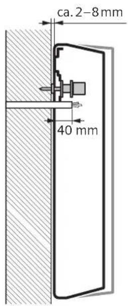
The electrical supply terminal can be fitted at the top (X) or bottom (Y). The sheath of the connection cable must extend for at least 40 mm into the appliance.
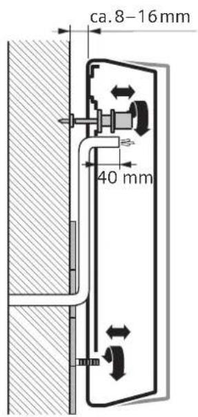
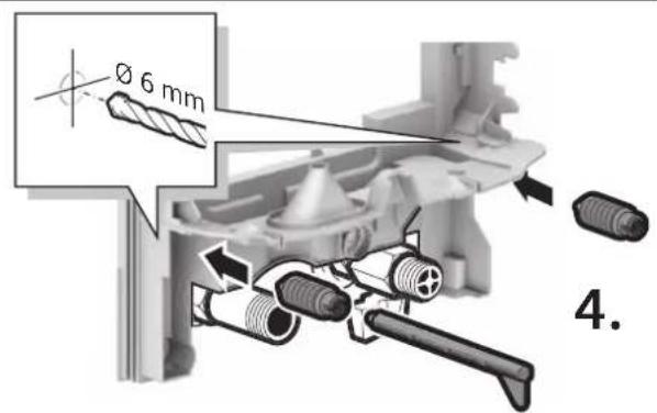
The distance to the wall is variable. You can compensate for any unevenness of the wall's surface. With a distance to the wall of 8–16 mm, insert the spacer and install the extender (Fig. III., 3. – 5.).
The appliance must be mounted securely on the wall. If necessary, attach it at the lower adjustable screws (Fig. III., 6.).
IV. Water connection
■ Connect the water supply, then open the cold water supply.
The appliance must be vented. To do so, open the warm water tap fully and flush out the appliance thoroughly for 1 minute.
v. Electrical connection/Mounting
Only for appliances with power selector switches:
Set the power using the power selector switch before connecting the wires to the mains connection terminal: Nominal output power left, reduced output right (Fig. V., 1.) and the set output marked on the ratings plate.
- Screw the wires tightly into the mains connection terminal.
■ Switch on the safety limiter (Fig. V., 3.)
■ Install the cover (Fig. V., 4. -7.).
Installation note
The installation of non plug-in ready appliances must be undertaken by the respective utility operator or by a qualified specialist company, who can also assist you when you are requesting the approval of the utility company for installation of the appliance.
VI. Startup
The device is compliant to IEC 61000-3-12.
First start-up
■ Switch on the fuses.
Setting the temperature.
Initial rinsing: Open the warm water tap fully and allow water to flow for at least 1 minute. Only then (for safety reasons) will the appliance begin to heat.
Tip: Should the appliance not start because of a reduced flow-rate, remove the perlator, shower head or similar before start and repeat the process.
- Explain the operation of the appliance to the user.
VII. Additional information
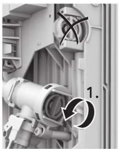
If the appliance does not have sufficient water flow due to low water line pressure in your domestic plumbing system, remove the flow-rate limiter (Fig. VII., 1. - 3.).
Priority circuit for the combination with electrical storage heaters: For operation with a priority circuit, a special load shedding relay BZ 45L21 (special accessory) is required. Other existing load shedding relays, with the exception of electronic load shedding relays, may malfunction (Fig. VII., Wiring diagram).
The control electronics must be coded when operated with a load shedding relay. Remove the keying nose on the electronics (Fig. VII., 4.).
Technical data
| DEE 1113 DEE 1821 | DEE 2427 | |||
| Rated output | [kW] 11/13 18/21 24/27 | |||
| Rated voltage | [V] 400 400 400 | |||
| Fuse protection [A] | 16/25 | 32 40 | ||
| Minimum conductor cross-section * | [mm2] 1.5/2.5 | 4 6 | ||
| Warm water flow at rated output with temperature increase from 12 °C to 38 °C (without flow-rate limiter) | [l/min] | 6.0/7.1 | 9.8/11.6 | 13.0/14.6 |
| 12 °C to 38 °C (with flow-rate limiter) | [l/min] | 5 | 7.6 | 9.3 |
| 12 °C to 60 °C | [l/min] | 3.3/3.8 | 5.3/6.2 | 7.1/7.9 |
| Start-up flow | [l/min] 2.5 2.5 | 2.5 | ||
| Start-up flow pressure ** | [MPa (bar)] | 0.009 (0.09) 0.009 (0.09) | 0.009 (0.09) | |
| Application area in water specific electric resistance at 15 °C | [Ωcm] ≥ 1 300 | ≥ 1 300 | ≥ 1 300 | |
| Rated pressure | [MPa (bar)] | 1.0 (10) | 1.0 (10) | 1.0 (10) |
| Maximum permissible supply temperature | [°C] | 20 20 20 | ||
| Maximum mains impedance at connection point | [Ω] | 0.433 | 0.067/0.104 0.067/0.104 | |
| Energy efficiency class | A | A | A | |
| Load profile | S | S | S | |
| Annual energy consumption | [kWh] | 477 479 479 | ||
| Daily energy consumption | [kWh] | 2.196 2.203 | 2.207 | |
| Sound power level | [dB] | 15 15 15 | ||
| Hot water heating energy efficiency | [%] | 38.6 | 38.5 | 38.5 |
| DES 1821 | DES 2427 | ||
| Rated output | [kW] 18/21 | 24/27 | |
| Rated voltage | [V] 400 | 400 | |
| Fuse protection [A] 32 | 40 | ||
| Minimum conductor cross-section * | [mm2] | 4 | 6 |
| Warm water flow at rated output with temperature increase from 12 °C to 38 °C (without flow-rate limiter) 12 °C to 38 °C (with flow-rate limiter) 12 °C to 60 °C | [l/min] [l/min] [l/min] | 9.8/11.6 7.6 5.3/6.2 | 13.0/14.6 9.3 7.1/7.9 |
| Start-up flow | [l/min] 2.5 | 2.5 | |
| Start-up flow pressure ** | [MPa (bar)] | 0.009 (0.09) | 0.009 (0.09) |
| Application area in water specific electric resistance at 15 °C | [Ωcm] ≥ 1 300 | ≥ 1 300 | |
| Rated pressure | [MPa (bar)] | 1.0 (10) | 1.0 (10) |
| Maximum permissible supply temperature | [°C] | 55 | 55 |
| Maximum mains impedance at connection point | [Ω] | 0.067/0.104 | 0.067/0.104 |
| Energy efficiency class | A | A | |
| Load profile | S | S | |
| Annual energy consumption | [kWh] | 479 | 479 |
| Daily energy consumption | [kWh] | 2.203 | 2.207 |
| Sound power level | [dB] | 15 | 15 |
| Hot water heating energy efficiency | [%] | 38.5 | 38.5 |
* Larger cable cross-sections may be required depending on the connection configuration.
** The pressure loss on the mixer must also be added.
Solar heated
Only for appliances that are suitable for solar heating systems:
The appliance can only heat prewarmed water to a max. of 60 °C . If the cold water supply exceeds a temperature of 55 °C , the water will not be warmed any further.
Important: The cold water supply temperature must not be higher than 55 °C!
If the cold water supply exceeds a temperature of 60 °C , a circuit breaker will trigger and shut the appliance off. Therefore, the residential plumbing must be equipped with a thermostatic premixer that will limit the cold water supply temperature to a max. of 55 °C by appropriately mixing in cold water.

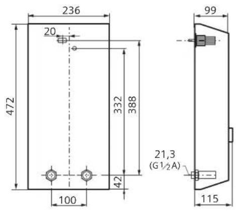
Dimensions
Special accessories
- Pipe kit DLE 02RBS for use of the appliance as an undersink appliance
- Priority switch (load shedding relay) Siemens BZ 45L21: for operation with a priority circuit
■ Mounting kit DLE 02AP: for surface mount installation
Environmentally-friendly disposal
This appliance is labelled in accordance with European Directive 2012/19/EU concerning used electrical and electronic appliances (waste electrical and electronic equipment – WEEE).
The guideline determines the framework for the return and recycling of used appliances as applicable throughout the EU.
Please ask your specialist retailer about current disposal facilities.
Subject to change without notice.
Product fiche concerning the "Commission delegated regulation (EU) No 812/2013"
| Trade mark: Dimplex | Trade mark: Dimplex |
| Model Identifier: DEE 1113 / DEE 1821 / DEE 2427 | Model Identifier: DES 1821 / DES 2427 |
| Load profile: S | Load profile: S |
| Energy efficiency class: A | Energy efficiency class: A |
| Energy efficiency class: 38.6/38.5/38.5% | Energy efficiency class: 38.5 / 38.5 % |
| Annual electricity consumption: 477/479/479 kWh | Annual electricity consumption: 479 / 479 kWh |
| Further possible load profiles:Load profile: –Energy efficiency class: –Annual electricity consumption: – | Further possible load profiles:Load profile: M / MEnergy efficiency class: 39.0 / 39.0 %Annual electricity consumption: 1 321 / 1 324 kWh |
| Thermostat temperature settings (factory setting): 60 °C | Thermostat temperature settings (factory setting): 60 °C |
| Sound power level: 15 dB | Sound power level: 15 dB |
| All specific precautions that shall be taken when the water heater is assembled, installed or maintained are described in the installation and operating instructions. | All specific precautions that shall be taken when the water heater is assembled, installed or maintained are described in the installation and operating instructions. |
natural_image
Illustration of an open book with a curved arrow pointing upward, no text or symbols present
text_image
1a.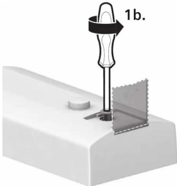
text_image
1b.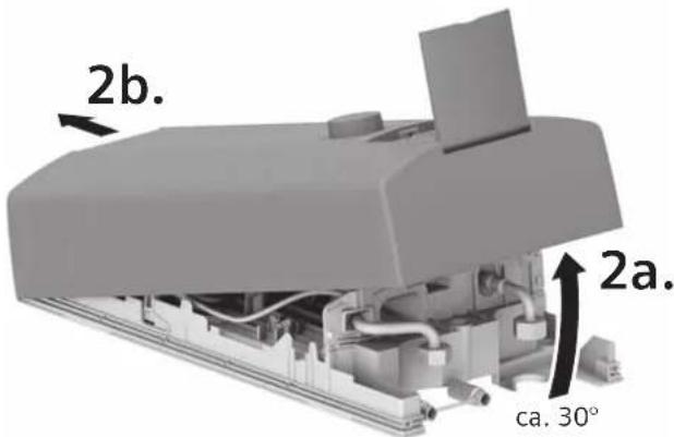
text_image
2b. 2a. ca. 30°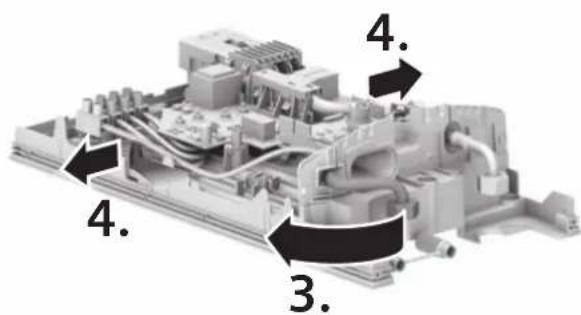
text_image
3. 4. 4. 4.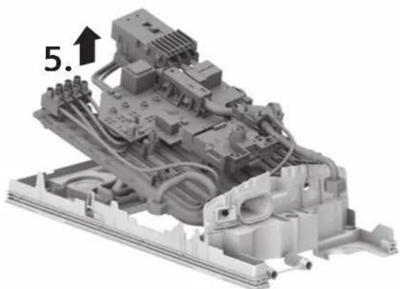
natural_image
3D mechanical assembly diagram showing internal components and wiring, labeled with number 5.1 (no readable text or symbols)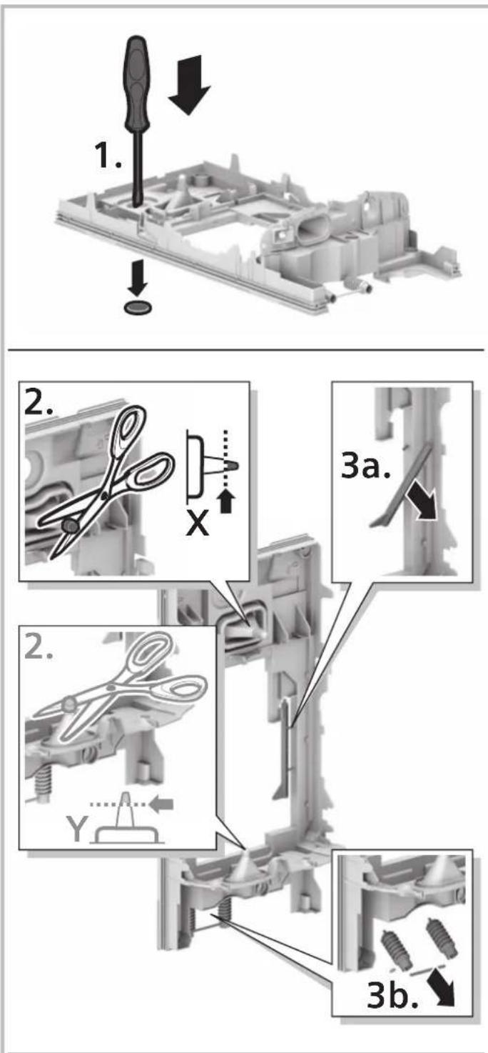
text_image
1. 2. 3a. 3b.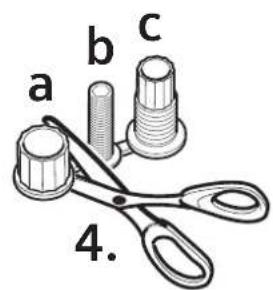
text_image
a b c 4.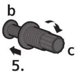
text_image
b c 5.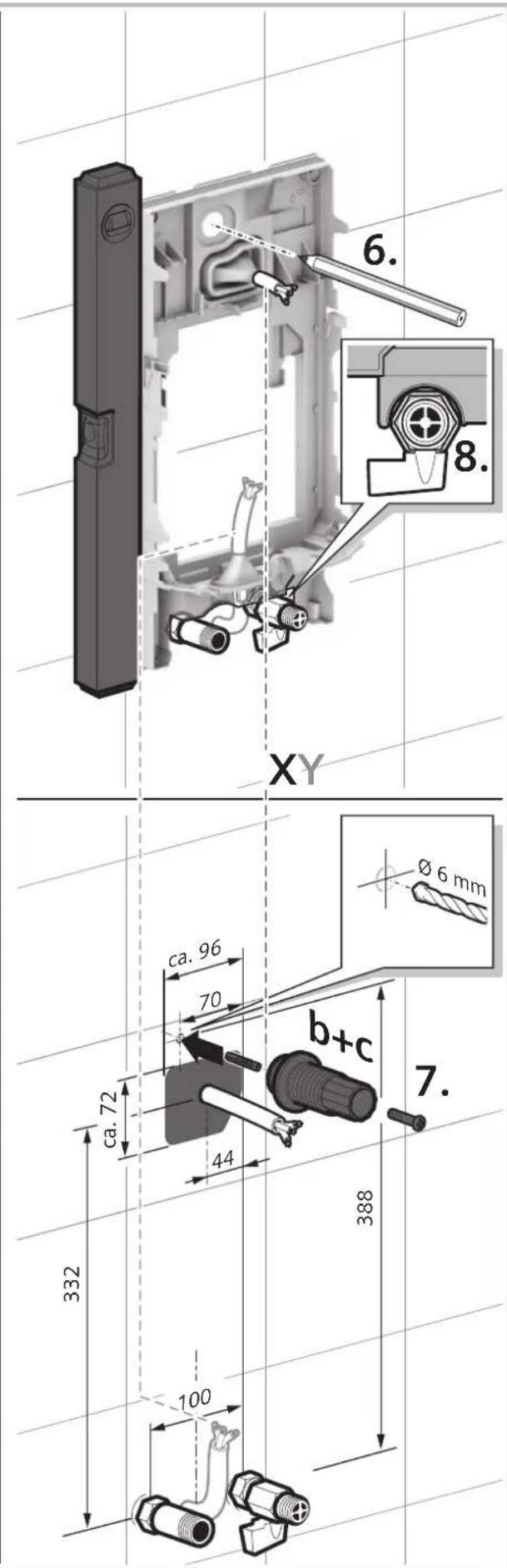
text_image
6. 8. XY ca. 96 70 b+c 7. 44 332 388 100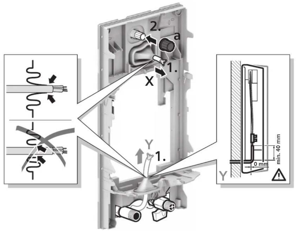
text_image
2. a 1. X Y 1. Y 0 mm min. 40 mm !X
text_image
ca. 2-8 mm 40 mmX
text_image
ca.8-16mm 40 mm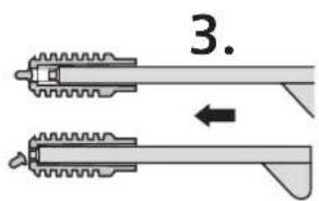
text_image
3.
text_image
Ø 6 mm 4.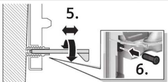
text_image
5. 6.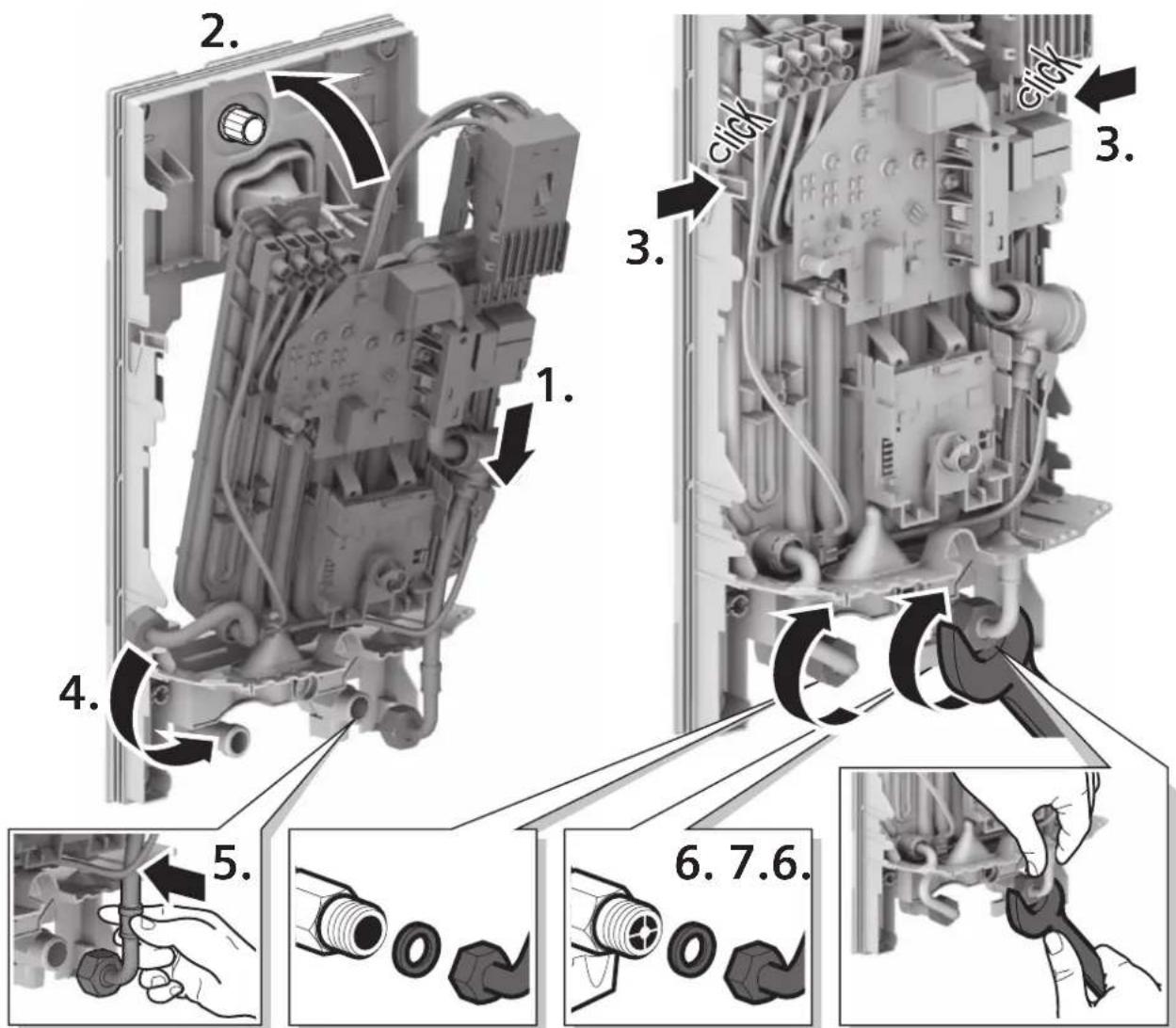
text_image
Technical diagram showing exploded view of a mechanical assembly with numbered components and labeled parts in Chinese1 Minute entlüften!
Vent for one minute!
natural_image
Illustration of a stainless steel faucet with water level indicator (no text or symbols)natural_image
Circular white knob with a black arrow pointing to the center, labeled '2.' (no text or symbols on the knob itself)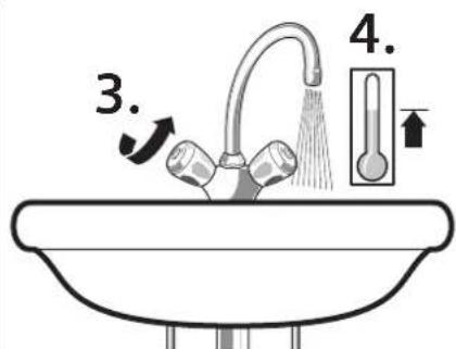
text_image
3. 4.VII.
natural_image
Close-up of a mechanical device with a circular arrow and cross mark, no visible text or symbols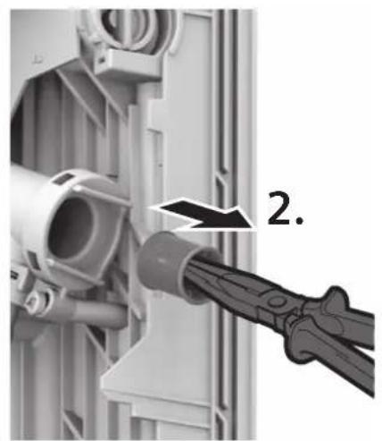
natural_image
Close-up of a mechanical component with a hand holding a tool, no visible text or symbols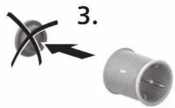
natural_image
Two mechanical components: a spherical component with cross-shaped features and an threaded cylindrical part, both without any visible text or symbols.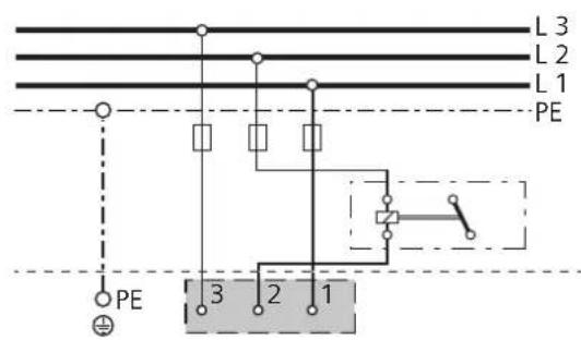
text_image
L 3 L 2 L 1 PE PE 3 2 1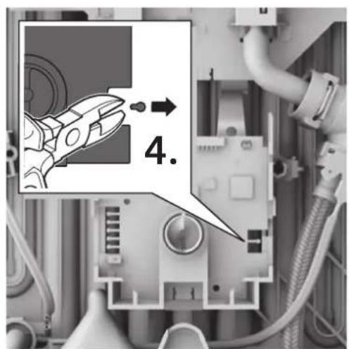
text_image
4.
natural_image
Exterior view of a white industrial water heater unit with control knob (no visible text or symbols)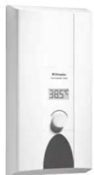
natural_image
Exterior view of a modern white appliance with a digital display showing 385°F, no visible text or symbols on the device itself.