
A136 - Vacuum Cleaner NILFISK - Free user manual and instructions
Find the device manual for free A136 NILFISK in PDF.
| Product type | Industrial vacuum cleaner for dry powders and granules |
| Brand | Nilfisk |
| Model | A136 |
| Intended use | Commercial use (hotels, schools, hospitals, factories, offices) for conveying single-component powders and granular products |
| Power supply | 230 V / 50 Hz, 1 kW |
| Maximum vacuum | 2150 mm H₂O |
| Maximum air flow | 2700 L/min (without hose or reduction) |
| Sound level (Lpf) | 70 dB(A) |
| Vibrations (ah) | ≤ 2.5 m/s² |
| Suction mouth diameter | 50 mm |
| Hopper capacity | 16 liters |
| Dimensions (L x W x H) | 550 x 400 x 870 mm |
| Weight | 18 kg |
| Operating temperature | -10 °C to +40 °C |
| Operating humidity | ≤ 85% |
| Maximum operating altitude | 800 m (up to 2000 m with reduced performance) |
| Main functions | Automatic cyclic suction with loading, unloading and filter cleaning by reverse air jet (models XR/XRF) |
| Adjustable loading time | 10 to 40 seconds |
| Adjustable pause time | 5 seconds (minimum) |
| Primary filter cleaning | Compressed air or replacement if torn/clogged |
| Standard filter (ref.) | 58 33109 |
| Bag filter (ref.) | 4581701303 |
| Recommended maintenance | Annual check by the manufacturer, inspection of seals and filters |
| Electrical protection | Residual current circuit breaker 30 mA / 30 ms |
Frequently Asked Questions - A136 NILFISK
User questions about A136 NILFISK
0 question about this device. Answer the ones you know or ask your own.
Ask a new question about this device
Download the instructions for your Vacuum Cleaner in PDF format for free! Find your manual A136 - NILFISK and take your electronic device back in hand. On this page are published all the documents necessary for the use of your device. A136 by NILFISK.
USER MANUAL A136 NILFISK
natural_image
Line drawing of a vacuum cleaner with coiled hose and control panel (no text or symbols)Translation of the original instructions
Table of contents
Instructions for use....2
Operator's safety 2
General information for using the machine 2
Proper uses 2
Improper Use....2
General recommendations....3
Residual Risks....3
EC Declaration of conformity.... 3
Description of the machine ....4
Machine Parts and Labels 4
Optional kits....4
Accessories 4
Packing and unpacking 4
Unpacking, moving, use and storage 4
Setting to work - connection to the power supply 5
Setting to work - connection to the pneumatic system (Only XR/XRF models) 5
Extensions....5
Supply pressure adjustment....6
Conveyor suitable for dry products....6
Technical data 7
Dimensions....7
Controls and indicators....8
Inspections prior to starting 8
Starting and stopping 8
Emergency stopping....8
Timer adjustment....8
At the end of a cleaning session 9
Maintenance, cleaning and decontamination....10
Primary filter cleaning.... 10
Main and absolute filter disassembly and replacement.... 10
Tightness inspection....11
Disposal....11
Air plant layout....11
Wiring diagrams 11
Recommended spare parts 12
Troubleshooting 12
Instructions for use
Read the operating instructions and comply with the important safety recommendations identified by the word CAUTION!
Operator's safety

CAUTION!


Before starting the machine, it is absolutely essential to read these operating instructions and to keep them on hand for consultation.
The machine can only be used by people who are familiar with the way it works and who have been explicitly authorised and trained for the purpose.
Before using the machine, the operators must be informed, instructed and trained on how to work it and for which substances its usage is permitted.

CAUTION!

The use of the machine by people (including children) with limited physical and mental capacities or lacking in experience and knowledge is strictly forbidden, unless they are supervised by a person who is experienced in the use and safe handling of the machine.
Children must be supervised to make sure they will not play with the machine.

CAUTION!

Before using the machine, always check that any hazardous condition has been eliminated and inform the persons in charge about any operational fault.
Check that all guards and protections are correctly mounted and that all safety devices are installed and efficient.
Repairs must only be carried out when the machine is at a standstill and disconnected from the electricity and air supply mains. Never ever carry out repairs without having first received the necessary authorization.

CAUTION!

Any changes made by the user without the Manufacturer's explicit authorization shall invalidate the warranty and hold the Manufacturer harmless from any and all liabilities for damages caused by faulty products.
General information for using the machine
Use the machine in accordance with the laws in force in the country where it is used.
Besides the operating instructions and the laws in force in the country where the device is used, the technical regulations for ensuring safe and correct operation must also be observed (Legislation concerning environmental and labour safety, i.e. European Union Directive 89/391/EC and successive Directives).
Do not perform any operation that could jeopardize the safety of people, property and the environment.
Comply with the safety indications and prescriptions in this instruction manual.
Proper uses
This machine is suitable for commercial use, in hotels, schools, hospitals, factories, shops, offices and apartment hotels for example, for hire and in any case for purposes other than normal domestic use.
This machine is suitable for transporting single-component powders and granular products only.
The machine has been designed to be used by one operator at a time.
This device consists of a motorized blower unit, with a filter unit and a container for collecting the material to be transported.
Improper Use

CAUTION!

The following use of the device is strictly forbidden:
■ Outdoors in case of atmospheric precipitation.
■ When not placed on horizontal level ground.
■ When the filter unit is not installed.
■ When the inlet and/or hose are turned to face parts of the human body.
■ Use without the cover on the vacuum unit.
■ Use without the guards, protective covers and safety systems installed by the manufacturer.
■ When the cooling vents are partially or totally clogged.
■ When the machine is covered with plastic or fabric sheets.
■ Use with the air outlet partially or totally closed.
■ When used in narrow areas where there is no fresh air.
■ When the cable or plug is damaged. If appliance is not working as it should, has been dropped, damaged, left outdoors or dropped into water, return it to an authorized service center.
■ Do not pull or carry by the cord, use the power cord as a handle, do not close a door on cord, or pull cord around sharp edges or corners. Do not run the appliance over the cord. Keep cord away from heated surfaces.
CAUTION!
The following use of the device is strictly forbidden:
■ It is severely forbidden to use the pneumatic feeder to suction up:
■ Vacuuming the following materials:
-
foodstuff (except XRF);
-
liquid substances;
-
harmful, toxic or radioactive substances;
-
substances that could create fire outbreaks or explosions;
-
substances whose nature could lead to the risk of biological or microbiological contamination.
Note: Fraudulent use is not admitted.
General recommendations
CAUTION!
If an emergency situation occurs:
■ Accident
■ Breakdown
■ Filter breakage
■ Fire outbreak
■ etc.
Disconnect the machine from the power supply and ask for assistance from qualified personnel. In case the user comes into contact with the vacuumed product, check the cautions shown on the safety technical sheet of the product, which must be made available from the employer.
CAUTION!
The machines must not be used or stored outdoors, or in damp places.
Residual Risks
After carefully considering the risks that are present in all machine operating phases, necessary measures were adopted in order to eliminate the risks for the operators, as far as possible, and/or limit or reduce the risks deriving from hazards that cannot be completely eliminated at the source.
During operations and/or maintenance, operators are exposed to certain residual risks which, due to the nature of the operations themselves, cannot be completely eliminated. Therefore the installer is responsible for providing additional information and/or hazard signals based on the location of machine installation and the material that is handled.
■ Risks due to electrical hazards during maintenance
DANGER
Risk of electrocution if accessing the electrical equipment during maintenance without having deactivated the electrical power supply.

FORBIDDEN

It is forbidden to work on the electric equipment before disconnecting the machine or its parts from the electrical line.

MANDATORY

Have the electrical maintenance operations performed by qualified personnel. Perform the checks on the electric equipment as specified in the manual.
■ Risks to the presence of residual high temperature after stopping the vacuum unit.
During maintenance and cleaning operations, the operator may come into contact while the machine is stopped, with parts of the vacuum unit with surfaces at high temperatures. Specific warning signs placed in strategic points indicate the hazard due to the presence of hot surfaces and the obligation for the user to wear personal protective equipment, in particular protective gloves.
The potentially hot parts (high temperatures) are identified as follows:

IT IS MANDATORY TO WEAR GLOVES

EC Declaration of conformity
Every machine comes with a EC Declaration of conformity. See fac-simile in fig. 9.
[ NOTE ]
The Declaration of conformity is an important document and should be kept in a safe place to be presented to the Authorities on request.
![NILFISK A136 - [ NOTE ] - 1](/content/2026/04/646590/images/3435c5f29084240809eb1d48a980a6d8d04f1964a379ec017642b593780f7807.jpg)
CAUTION!

The Declaration of Conformity refers only to the conveyor manufactured by Nilfisk-CFM, without delivery piping.
■ The use of delivery piping without suitable brackets fitted by the installer can compromise the stability of the conveyor, causing it to tip over.
■ The conveyor electrical connection must be performed by the installer's qualified personnel, a wrong connection can be dangerous for safety.
The installer fitting the conveyor in line with the rest of the system must issue a Declaration of Conformity for the correctly installed system.
Description of the machine
Machine Parts and Labels
Figure 1
| 1. | Hopper |
| 2. | Product hose |
| 3. | Pick-up probe hose |
| 4. | Electrical panel |
| 5. | Identification plate |
| 6. | Shut-off valve |
| 7. | Maximum level sensor |
| 8. | Panel power plate Indicates that the panel is powered by the voltage indicated on the data plate |
The access to the panel is allowed to specialized personnel only who, before touching the electrical equipment, must disconnect the machine from its power source by turning the main switch to 0 - (off) and by removing the plug from the electrical socket.
Feeders transfer the products to the production centres by means of a powerful air flow created by a vacuum unit. The power supply is equipped with a single-phase motor, suitable for non-continuous use. Under no circumstances must it be used to vacuum liquids.
The loading hopper is entirely made of stainless steel. The electrical circuit is timed. The hose conveying the product is non-toxic/antistatic with the stainless steel probe tube at the end.
The vacuum unit creates vacuum inside the hopper. The product is suctioned into the hopper by means of the hose and the probe pipe. When these reach the level set by the timer, the vacuum unit stops and the vacuum is cut off.
After this, the slide valve opens and permits the product to drop into the user machine. Once this phase is completed, a counterflow of air cleans the filter at the top of the hopper (only on XR/XRF models).
The machine is ready for a new cycle. The loading, discharge and filter cleaning times can all be adjusted by means of programmer installed in the electrical panel.
Optional kits
On request, the machine can be supplied with optional kits already installed. However, they can also be installed at a later date.
Please contact the sales network for further details.
Instructions describing how to fit the optional kits and the relative operation and maintenance manuals are supplied together with the optional kits.

CAUTION!

Use only supplied and authorised genuine spare parts.
Accessories
Various accessories are available; refer to the manufacturer's accessory catalogue.

CAUTION!

Use only genuine accessories supplied and authorised by the manufacturer.
Packing and unpacking
All the dispatched equipment has been thoroughly checked before being delivered to the haulage contractor.
On arrival, check the machine to see that it has not been damaged during transport. If this is the case, immediately lodge a complaint with the haulage contractor.
Dispose of the packing materials in compliance with the laws in force.
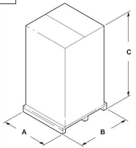
Figure 2
| Model A (mm) | B (mm) C | (mm) kg (*) | ||
| A136 - A128 500 | 500 860 20 |
(*) Weight with packing
Unpacking, moving, use and storage
To unpack the vacuum unit, remove the retainers with a hammer and a screwdriver.
Also remove the fastening devices placed by the manufacturer when packing, by using suitable tools.
Operate on flat, horizontal surfaces.
The load-bearing capacity of the surface the machine is placed on must be suitable for bearing its weight.
If the device is to work in a fixed position, allow wide space around the device in order to ensure freedom of the movement and allow the maintenance staff to operate with ease.
CAUTION!
The manufacturer shall not be liable for any damages caused to the machine during lifting, when the lifting equipment supplied by the manufacturer is not used.
CAUTION!
When several supporting platforms are provided, the supporting platform to which the machine is anchored must be handled with a forklift truck that can provide adequate capacity. Then unpack the machine by laying it down on a flat and horizontal surface that can provide adequate capacity for the vacuum cleaner weight.
Setting to work - connection to the power supply

CAUTION!
■ Make sure there is no evident sign of damage to the machine before starting work.
■ Before plugging the machine into the electrical mains, make sure the voltage rating indicated on the data plate corresponds to that of the electrical mains.
■ Connect the plug into a socket with a correctly installed ground contact/connection. Make sure that the machine is turned off.
■ The plugs and connectors of the connection cables must be protected against splashes of water.
■ Check that for proper connection to the electrical mains.
■ Use the machine only when the cables that connect to the electricity mains are in perfect condition (damaged cables could lead to electric shocks!).
■ Regularly check there are no signs of damage, excessive wear, cracks or ageing on the electric cable.

CAUTION!
When the device is operating, do not:
■ Crush, pull, damage or tread on the cable that connects to the electrical mains.
■ Only disconnect the cable from the electrical mains by removing the plug (do not pull the cable).
■ Only replace the electric power cable with one of the same type as the original: H07 RN-F, The same rule applies if an extension is used.
- The cable must be replaced by the manufacturer's Service Centre staff or by equivalent qualified personnel.
The system safety officers must:
■ Prevent any improper use or manoeuvre.
■ Make sure that the safety devices are not removed or tampered with.
■ Check that all maintenance operations are regularly performed;
■ Make sure that no machine part (couplings, holes, etc.) is modified to attach additional devices;
■ Make sure that only original Nilfisk spare parts are used.
NOTE
The user shall be responsible for ensuring that installation complies with the all relevant local provisions. The equipment must be installed by qualified technicians who have read and understood the instructions herein.
Setting to work - connection to the pneumatic system (Only XR/XRF models)
CAUTION!
■ Make sure there is no evident sign of damage to the machine before starting work.
■ Before connecting the machine to the pneumatic supply, make sure the network supplies condensate-free air at the pressure indicated in this manual (see technical data).
■ Regularly check there are no signs of damage, excessive wear, cracks or ageing on the connecting hose.
CAUTION!
When the device is operating, do not:
■ Crush, pull, damage or tread on the connecting hose.
■ Only replace the supply hose with one of the same type as the original.
The system safety officers must:
■ Prevent any improper use or manoeuvre.
■ Make sure that the safety devices are not removed or tampered with.
■ Check that all maintenance operations are regularly performed;
■ Make sure that no machine part (couplings, holes, etc.) is modified to attach additional devices;
■ Make sure that only original Nilfisk spare parts are used.
NOTE
The user shall be responsible for ensuring that installation complies with the all relevant local provisions. The equipment must be installed by qualified technicians who have read and understood the instructions herein.
Extensions
If an extension cable is used, make sure it is suitable for the power input and protection degree of the machine.
| Max power (kW) | 3 | 5 | 15 | 22 |
| Minimum section (mm2) | 2.5 | 4 | 10 | 16 |
| Maximum length (m) | 20 | |||
| Cable | H07 RN - F | |||

CAUTION!
Sockets, plugs, cable clamps, connectors and installation of the extension cable must maintain the IP protection degree of the machine, as indicated on the data plate.

CAUTION!

The machine power socket must be protected by a differential circuit-breaker with surge current limitation, that shuts off the power supply when the current discharged to the ground exceeds 30 mA for 30 msec. or an equivalent protection circuit.

CAUTION!

Never spray water on the machine: this could be dangerous for persons and could short circuit the power supply.
Supply pressure adjustment
The air plant must have a filter/reducer since the air that reaches the solenoid valves must be filtered.
The air pressure must be between a maximum 6 bar and a minimum 4 bar.
Conveyor suitable for dry products
[ NOTE ]
The supplied filters (if equipped) must be properly installed.
![NILFISK A136 - [ NOTE ] - 1](/content/2026/04/646590/images/eee8972a41b5841f9b7729d48de93168a5e2754db3a445e7179ef0d3039b63ff.jpg)
CAUTION!

Comply with the safety regulations governing the materials to be conveyed.
Technical data
| Parameter | Units of measurement | A136 A128 | |
| Voltage V 230/50 | |||
| Power rating kW 1 | |||
| Max vacuum mm H20 2150 | |||
| Maximum air flow rate without hose and reductions | L/m' 2700 | ||
| Sound pressure level (Lpf) (EN60335-2-69) (*) | dB(A) 70 | ||
| Vibration, ah (**) m/s2 ≤2.5 | |||
| Vacuum inlet (diameter) mm | 50 | 40 | |
| Minimum loading time | seconds | 10 | |
| Maximum loading time | seconds | 40 | |
| Filter cleaning minimum time | seconds | 5 | |
| Hopper maximum capacity | litres | 16 | 9 |
| Weight | kg | 18 | 14 |
(*) Measurement uncertainty KpA < 1.5 dB (A). Noise emission values obtained according to EN-60335-2-69
(**) Total value of vibration output to the operator arm and hand
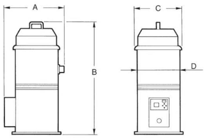
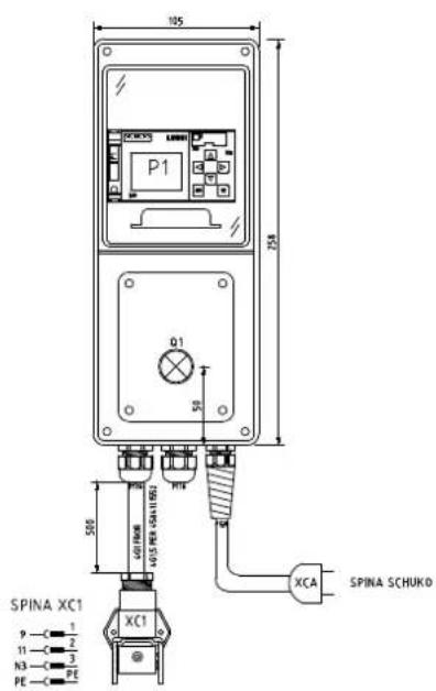
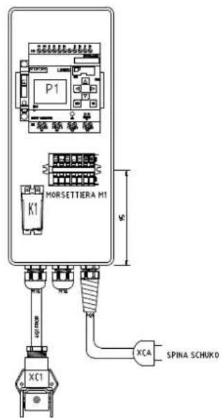
Dimensions
Figure 3
| Model | A136 | A128 |
| A (mm) | 550 | 440 |
| B (mm) | 870 | 785 |
| C (mm) | 400 | 300 |
| D (mm) | 360 | 280 |
| Weight (kg) | 18 | 14 |
[ NOTE ]
■ Storage conditions:
Temperature: -10^ ÷ +40^
Humidity: ≤ 85%
■ Operating conditions:
Maximum altitude: 800 m
(Up to 2,000 m with reduced performances)
Temperature: -10°C ÷ +40°C
Humidity: ≤ 85%
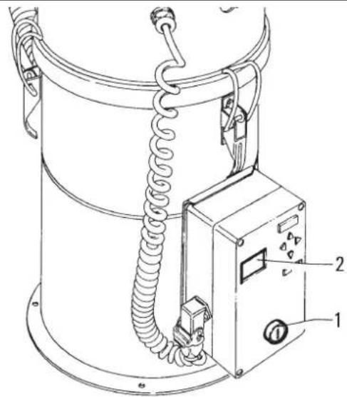
Controls and indicators
Figure 4
- Green luminous push-button
Press to start the machine.
Press again to stop it.
- Bright display
When lit, it indicates that the feeder is running.
Inspections prior to starting
Before starting, check that:
■ Make sure that the cover protecting the electrical and air operated components of the hopper is in place.
■ Make sure that the pick-up hose and the single-tube probe are properly connected.
■ Make sure that the single-tube probe is immersed in the product.
Starting and stopping
Figure 4
■ Press the button 1.
The feeder automatically performs the following cyclic operations: Vacuum the product (hopper loading) for 40 seconds, discharge of the product from the hopper for 15 seconds, cleaning of the primary filter with a counterflow air jet for 5 seconds (models XR/XRF).
Emergency stopping
Press the stop button 1 at the end of the work cycle.

CAUTION!

The motors and internal components of the machine will still be electrically powered.
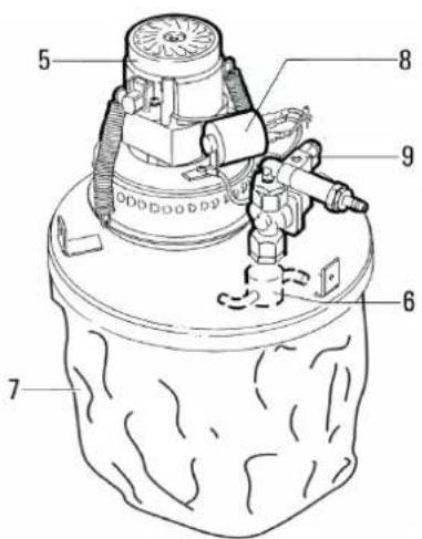
Timer adjustment
Figure 5

CAUTION!

All installation or maintenance work on electrical parts must be carried out by qualified personnel.
■ Turn main switch (1) to position "0".
- Open the electrical board and turn the main switch to position "I".

CAUTION!

In this condition, the electric panel remains powered with the consequent risk of electric shock.
■ Adjust Timer (2, Fig. 6) as indicated in the following paragraph.
■ After adjusting the times, turn main switch (1) to position "0".
■ Close the electrical board with the key provided.
[ NOTE ]
The above mentioned times are standard factory defaults. These times may vary depending on the nature and size of the product.
Changing the time settings
B01 = Product load time
B02 = Pause time
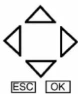
To change the time settings, switch to parameter entry mode by pressing key "ESC".
I:123456
Mo 09:00
Q:1234 RUN

Select with the down arrow key to select the "SET PARAM" option, then press "OK".

Stop
Set param Set... Prg Name
Press or to display the factory default times.
Parameter
B 01 : T
Value set for parameter
T = 12:00 s
Current parameter value
Ta = 00 : 00
Time setting entered in the factory
Preset default time
Actual loading time
B 01 : T
T = 00:10 m
Ta = 00 : 00
Preset default pause time
Actual time
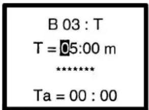
B 02 : T
T = 5:00s
Ta = 00 : 00
1) Press "OK" in the block you wish to change.
2) Move the cursor to the position you want to modify.
3) Change the value.
4) Finally, press "OK" to confirm.
5) Press "ESC" twice to return to the main mask.
1) ◀ or ▶ Move
2) ▼ or ▲ Change value
3) Confirm:OK key
At the end of a cleaning session
■ Switch the conveyor off.
■ Clean the conveyor as described in “Maintenance, cleaning and decontamination” paragraph.
■ Store the device in a dry place, out of reach of unauthorized people.
■ Close the outlet when the machine is not in use or being transported.
Maintenance, cleaning and decontamination

CAUTION!

Disconnect the machine from its power source before cleaning, servicing, replacing parts or converting it to obtain another version/variant.
- Carry out only the maintenance operations described in this manual.
■ Use only original spare parts.
■ Do not modify the machine in any way.
Failure to comply with these instructions could jeopardize your safety. Moreover, such action would immediately void the EC declaration of conformity/ incorporation issued with the machine.

CAUTION!

For maintenance procedures not described in this manual, please contact the manufacturer's technical support or sales network.

CAUTION!

To guarantee the safety level of the machine, only original spare parts supplied by the manufacturer should be used.

CAUTION!

The precautions described below must be taken during all maintenance operations, including cleaning and replacing the primary and absolute filters.
■ To allow the user to carry out the maintenance operations, the machine must be disassembled, cleaned and overhauled as far as is reasonably possible, without causing hazards for the maintenance staff or other people. The suitable precautions include decontamination before disassembling the machine, adequate filtered ventilation of the exhaust air from the room in which it is disassembled, cleaning of the maintenance area, and suitable personal protection.
■ The external parts of the machine must be decontaminated by cleaning and vacuuming methods, dedusted or treated with sealant before being taken out of a hazardous zone.
■ All parts of the machine must be considered as contaminated when they are removed from the hazardous zone and appropriate actions must be taken to prevent dust from dispersing.
■ When maintenance or repair procedure are carried out, all the contaminated elements that cannot be properly cleaned, must be eliminated.
■ These elements must be disposed of in sealed bags in accordance with applicable regulations and local laws on the disposal of such material.
■ This procedure must also be followed for filter disposal (primary and absolute filters).
■ Compartments that are not dust-tight must be opened with suitable tools (screwdrivers, wrenches, etc.) and thoroughly cleaned.
■ A check must be carried out by the manufacturer or the personnel of the same at least once a year. For example:
Check the air filters to find out whether the air-tightness of the machine has been impaired in any way and make sure that the electric control panel operates correctly.
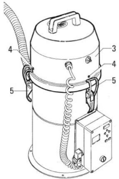
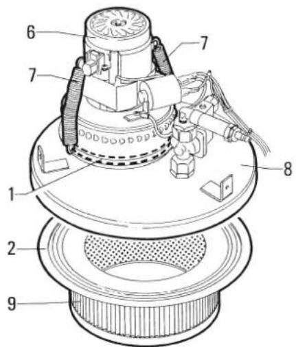
Primary filter cleaning
Figure 5
To check the status of the filter:
- Loosen the hooks (4).
- Remove the cover (3).
- Lift the cover (8).
- Check the condition (9) of the filter. The filter must be replaced if it is torn or worn through wear. If the filter is clogged, clean it with compressed air.
- Check the condition of the filter gasket.
- Assemble the components in the reverse order of disassembly.
Main and absolute filter disassembly and replacement

CAUTION!

When the machine is used to vacuum hazardous substances, the filters become contaminated, therefore:
■ Work with care and avoid spilling the vacuumed dust and/or material;
■ place the disassembled and/or replaced filter in a sealed plastic bag;
■ close the bag hermetically;
■ dispose of the filter in accordance with the laws in force.

CAUTION!

Filter replacement is a serious matter. The filter must be replaced with one of identical characteristics, filtering surface and category.
Otherwise the machine will not operate correctly.
Before proceeding with these operations, turn off the machine and remove the plug from the power socket.

CAUTION!

Before performing these operations, clean the filter as described in the “Maintenance, cleaning and decontamination” paragraph.

CAUTION!

Take care not to raise dust during this operation. Wear a P3 mask and other protective clothing plus protective gloves (DPI) suited to the hazardous nature of the dust collected, refer to the laws in force.
Tightness inspection
To ensure optimum efficiency of the feeder, the entire pipe network must be perfectly air-tight.
In particular, make sure that the pick-up hose is in good conditions and properly fitted. The hoses must be replaced if they are torn or broken. Also check for clogging inside the hose and inlet.
Remove any material deposited in the inlet. Make sure that connecting hoses are in a good condition and correctly fixed. If the hoses are damaged, broken or badly connected to the unions, they must be replaced.
When sticky materials are treated, check for possible clogging along the hose, in the inlet and on the baffle plate inside the filtering chamber. To clean, scrape the inlet from the outside to remove deposits.
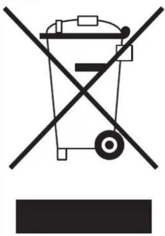
Disposal
Figure 6
The crossed-out wheeled bin symbol on the equipment indicates that used electrical and electronic equipment must be collected and disposed of separately from household waste. The correct disposal of the equipment will help prevent potential negative consequences for the environment and human health.
Electrical and electronic household equipment must be disposed of at the separate collection points in the residence area. Please note that commercial electrical and electronic equipment should be disposed of separately from the municipal waste stream. We will be pleased to inform you about suitable disposal options.
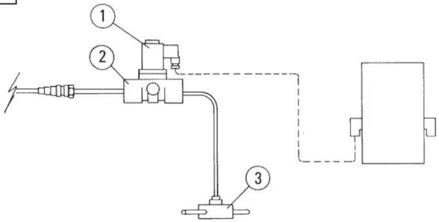
Air plant layout
Figure 7
| Name | Code Description | Q.ty | |
| 1 58 | 39158 Coil 1 | ||
| 2 58 | 47523 Solenoid valve 1 | ||
| 3 | 58 32105 | A128 rotary coupling | 1 |
| 58 32252 | A136 rotary coupling | 1 |
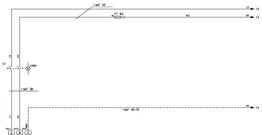
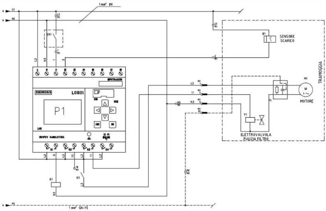
Wiring diagrams
Figure 8
| Name | Code Description | Q.ty | |
| P1 | 4083901808 | LOGO controller | 1 |
| K1 | 40839017774083901778 | 110VAC relay | 1 |
| 40839017764083901778 | 230VAC relay | 1 | |
| Q1 | 8 395258 39531 | Green luminous switch | 1 |
| M1 | 4083901590 | 2.5mmq 7 pin terminal | 1 |
| 4083901603 | 2.5mmq fuse box terminal | 1 | |
| XC1 | 58 395198 39346 | 3P connector | 1 |
Recommended spare parts
The following is a list of spare parts that should be kept ready at hand in order to speed up maintenance operations. Refer to the manufacturer's spare parts catalogue when ordering spare parts.
| Name | Model | ||
| A136 A128 | |||
 | Standard filter 58 33109 58 33091 | ||
 | Bag filter 4581701303 - | ||
 | 230V 1000W Motor 4089100275 | ||
| 120V 1000W Motor 4089100276 | |||
 | Gasket 8 17025 8 17024 | ||
 | Motor gasket 8 17054 | ||
 | Girol 58 32252 58 32105 | ||
Troubleshooting
Problem Cause Remedy
GB
| The conveyor does not load the product | Cover open Close cover. | |
| Cover gasket broken or in wrong position | Position the cover gasket correctly or replace. | |
| Locks not closed or no gasket | Close locks or fit gasket. | |
| Conveyor loads too much product | Loading time too long | Adjust timers. |
| Pause time too short | Adjust timers. | |
| Conveyor doesn't load enough product | Loading time too short | Adjust timers. |
| Pause time too long | Adjust timers. | |
| Gasket in wrong position or missing | Check gasket and replace if necessary. | |
| Conveyor won't start | No mains power | Turn main switch to position "1". |
| Check electrical connections. | ||
| The conveyor does not stop when the capsules reach the maximum level | Level sensor wrongly positioned or not much sensitive | Place the level sensor correctly or adjust is sensitiveness |
2
3
4
5
6
natural_image
Symbolic illustration of a trash bin crossed with two diagonal lines, no text or labels present7
8
9


- Translation of the original instructions
- Table of contents
- Instructions for use....2
- Description of the machine ....4
- Maintenance, cleaning and decontamination....10
- Recommended spare parts 12
- Troubleshooting 12
- Instructions for use
- Operator's safety
- CAUTION!
- General information for using the machine
- Proper uses
- Improper Use
- General recommendations
- Residual Risks
- DANGER
- FORBIDDEN
- MANDATORY
- IT IS MANDATORY TO WEAR GLOVES
- EC Declaration of conformity
- [ NOTE ]
- Description of the machine
- Machine Parts and Labels
- Optional kits
- Accessories
- Packing and unpacking
- Unpacking, moving, use and storage
- Setting to work - connection to the power supply
- NOTE
- Setting to work - connection to the pneumatic system (Only XR/XRF models)
- Extensions
- Supply pressure adjustment
- Conveyor suitable for dry products
- Controls and indicators
- Figure 4
- Inspections prior to starting
- Starting and stopping
- Emergency stopping
- Timer adjustment
- Figure 5
- Changing the time settings
- At the end of a cleaning session
- Maintenance, cleaning and decontamination
- Primary filter cleaning
- Main and absolute filter disassembly and replacement
- Tightness inspection
- Disposal
- Air plant layout
- Wiring diagrams
- Recommended spare parts
- Troubleshooting
- 9
Brand : NILFISK
Model : A136
Category : Vacuum Cleaner