R1001E - Air-conditioner LG - Free user manual and instructions
Find the device manual for free R1001E LG in PDF.

User questions about R1001E LG
0 question about this device. Answer the ones you know or ask your own.
Ask a new question about this device
Download the instructions for your Air-conditioner in PDF format for free! Find your manual R1001E - LG and take your electronic device back in hand. On this page are published all the documents necessary for the use of your device. R1001E by LG.
USER MANUAL R1001E LG
ROOM AIR CONDITIONER OWNER'S MANUAL
Please read the operating instructions and safety precautions carefully and thoroughly before installing and operating your room air conditioner.
MANUEL D'UTILISATION CLIMATISEUR DE FENÊTRE
Safety Precautions......3
Operating Instructions ....8
Care and Maintenance......11
Hardware Installation ....13
Common Issues ....27
FOR YOUR RECORDS
Write the model and serial numbers here:
Model #
Serial #
You can find them on a label on the side of each unit.
Dealer's Name
Date Purchased
■ Staple your receipt to this page in the event you need it to prove date of purchase or for warranty issues.

READ THIS MANUAL
Inside you will find many helpful hints on how to use and maintain your air conditioner properly. Just a little preventive care on your part can save you a great deal of time and money over the life of your air conditioner.
You'll find many answers to common problems in the chart of troubleshooting tips. If you review our chart of
Troubleshooting Tips first, you may not need to call for service at all.

PRECAUTION
- Contact the authorized service technician for repair or maintenance of this unit.
- Contact the installer for installation of this unit.
- The air conditioner is not intended for use by young children or invalids without supervision.
- Young children should be supervised to ensure that they do not play with the air conditioner.
- When the power cord is to be replaced, replacement work shall be performed by authorized personnel only using only genuine replacement parts.
- Installation work must be performed in accordance with the National Electric Code by qualified and authorized personnel only.
natural_image
Simple line drawing of a family enjoying a round table with drinks and snacks, palm trees in background (no text or symbols)Safety Precautions
To prevent injury to the user or other people and property damage, the following instructions must be followed.
■ Incorrect operation due to ignoring instruction will cause harm or damage. The seriousness is classified by the following indications.
WARNING
This symbol indicates the possibility of death or serious injury.
CAUTION
This symbol indicates the possibility of injury or damage to properties only.
■ Meanings of symbols used in this manual are as shown below.

Be sure not to do.

Be sure to follow the instruction.
WARNING
■ Installation
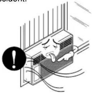
Always install the expansion panel(s).
- No installation may cause fire and electric shock accident.
text_image
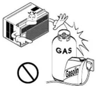
Cartoon illustration showing a person inside an air conditioner with a warning symbol and text 'Error!'Do not use the power cord near flammable gas or combustibles such as gasoline, benzene, thinner, etc.
- It may cause explosion or fire.
text_image
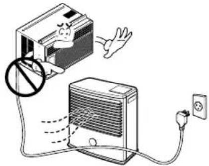
GAS GasolinDo not place the power cord near a heater.
- It may cause fire and electric shock.
natural_image
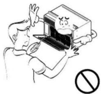
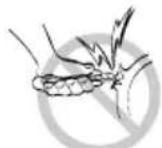
Illustration of a cartoon-style air conditioner with a warning sign and power outlet, no text or symbols present.Do not disassemble or modify products.
- It may cause failure and electric shock.
natural_image
Cartoon illustration of a person holding a laptop with a distressed face, no text or symbols present■ Operation
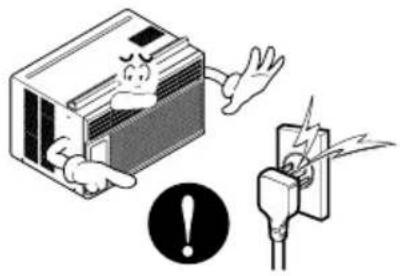
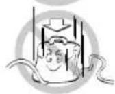
Plug in the power plug properly.
- Otherwise, it will cause electric shock or fire due to heat generation or electric shock.
natural_image
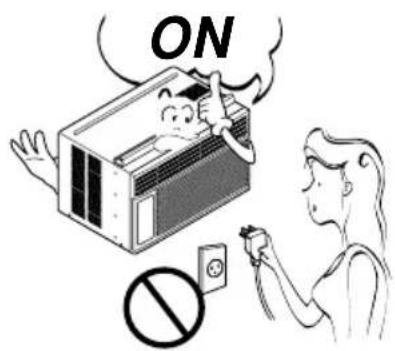
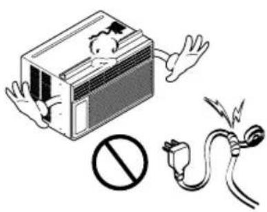
Illustration of an air conditioner unit with warning symbols and a plug, no text or labels presentDo not operate or stop the unit by inserting or pulling out the power plug.
- It will cause electric shock or fire due to heat generation.
text_image
ONDo not damage or use an unspecified power cord.
- It will cause electric shock or fire.

Do not modify power cord length.
- It will cause electric shock or fire due to heat generation.
natural_image
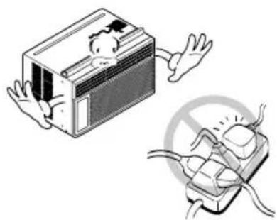
Illustration of an air conditioner unit with a warning symbol and plug, no text presentDo not share the outlet with other appliances.
- It will cause electric shock or fire due to heat generation.
natural_image
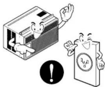
Illustration of a cartoon car with arms and legs, and a plug with a prohibition symbol (no text or labels)Always plug into a grounded outlet.
- No grounding may cause electric shock (See Installation Manual).
natural_image
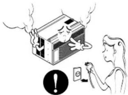
Illustration of two cartoon characters inside air conditioners, one waving and the other holding a document with a warning symbol (no text or labels)Unplug the unit if strange sounds, odors, or smoke come from it.
- Otherwise it may cause fire and electric shock accident.
natural_image
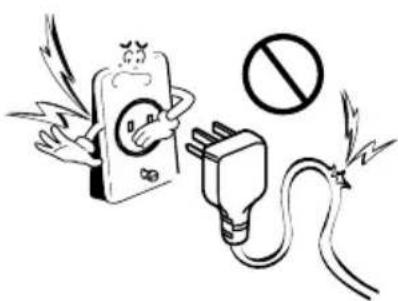
Illustration of a person using an electric shock absorber to clean a damaged cabinet, with warning symbol and electrical socket (no text or labels)Do not use the socket if it is loose or damaged.
- It may cause fire and electric shock.
text_image
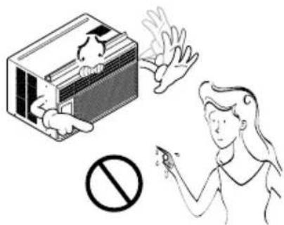
Cartoon illustration showing a phone with wings and a plug connected to a prohibition symbol, indicating an electrical hazard or prohibition.Do not operate with wet hands or in damp environment.
- It will cause electric shock.
text_image
Safety warning illustration showing a hand holding a device with a 'No' symbol, indicating no hazard or absence of a device.Do not allow water to run into electric parts.
- It will cause failure of machine or electric shock.
natural_image
Illustration of a distressed refrigerator with a large 'no' symbol above it, no text or symbols present.Leave the door closed while the air conditioner is running.
- It is not designed to cool the entire house.

natural_image
Illustration of a person hanging from a computer unit with an open door, emitting exhaust smoke (no text or symbols)Ventilate before operating air conditioner when gas goes out.
• It may cause explosion, fire, and burn.
natural_image
Illustration of a person opening a refrigerator with a warning symbol (no text or labels)CAUTION
■ Installation
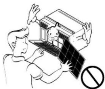
Never touch the metal parts of the unit when removing the filter.
• They are sharp and may cause injury.
natural_image
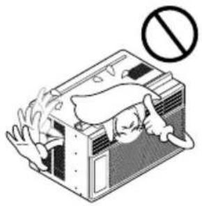
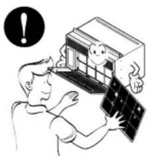
Illustration of two people assembling a solar panel with a prohibition symbol (no text or labels)Do not block the inlet or outlet.
• It may cause failure of appliance or accident.
natural_image
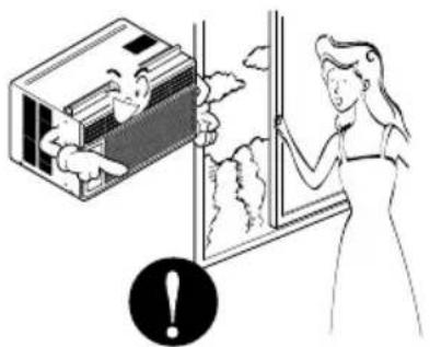
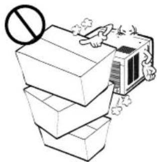
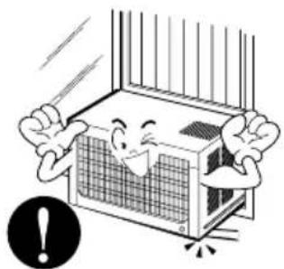
Illustration of stacked cardboard boxes with a prohibition symbol above, and an air conditioner unit emitting exhaust smoke (no text or symbols)Ensure that the outer case is not damaged by age or wear.
- If leaving appliance damaged, there is concern of damage due to the falling of product.
natural_image
Cartoon illustration of a smiling air conditioner unit with arms and legs, showing shock (no text or symbols)■ Operation
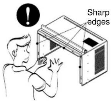
Be cautious not to touch the sharp edges when installing.
- It may cause injury.
text_image
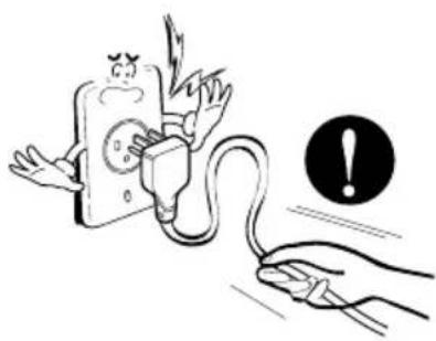
Sharp edgesHold the plug by the head when taking it out.
- It may cause electric shock and damage.
natural_image
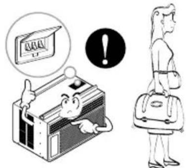
Illustration of a hand holding an electrical plug connected to a device with a warning symbol (no text or labels)Turn off the main power switch when not using it for a long time.
• Prevent accidental startup and the possibility of injury.
natural_image
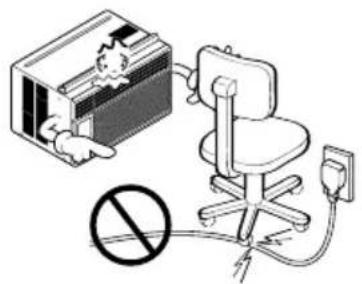
Illustration showing a cartoon character pointing at a computer screen and a person carrying bags, with an exclamation mark in the circle (no text or symbols present)Do not place heavy object on the power cord and take care so that the cord should not be pressed.
• There is danger of fire or electric shock.
text_image
Diagram showing a device connected to an office chair with a prohibition symbol below, indicating no liability or prohibition.Turn off the power and breaker firstly when cleansing the unit.
- Since the fan rotates at high speed during operation, it may cause injury.
text_image
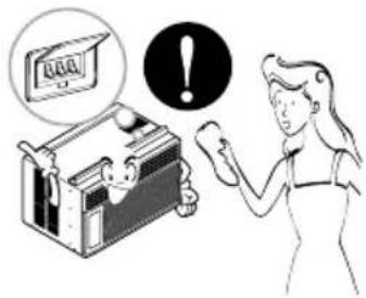
Illustration showing a person using a device to interact with a machine, with a warning symbol and a 'OK' icon nearby.Always insert the filter securely. Clean it every two weeks.
• Operation without filters will cause failure.
natural_image
Illustration of a person using a computer with a cartoon character on the screen (no text or symbols)If water enters the product, turn off the the power switch of the main body of appliance. Contact service center after taking the power-plug out from the socket.
text_image
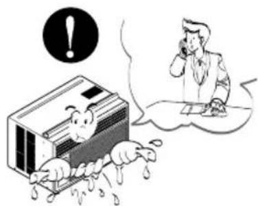
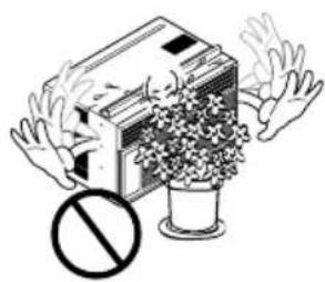
Illustration showing a person using a phone to call for an alarm, with a cartoon character inside a container and a speech bubble containing an exclamation mark.Do not put a pet or house plant where it will be exposed to direct air flow.
• This could injure the pet or plant.
natural_image
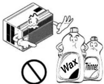
Illustration of a person holding a box with a prohibition symbol below (no text or symbols present)Use a soft cloth to clean. Do not use wax, thinner, or a strong detergent.
• The appearance of the air conditioner may deteriorate, change color, or develop surface flaws.
text_image
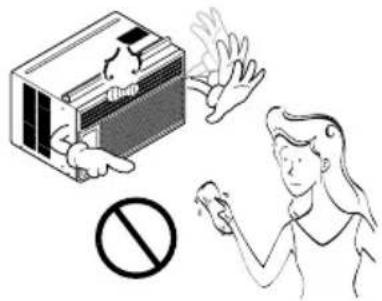
Wax ThinnerDo not clean the air conditioner with water.
• Water may enter the unit and degrade the insulation. It may cause an electric shock.
text_image
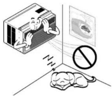
Safety warning illustration showing a device emitting smoke and a person using a handheld device.Do not use this appliance for special purposes such as pets, foods, precision machinery, or objects of art.
- It is an air conditioner, not a precision refrigeration system.
natural_image
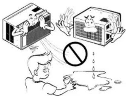
Illustration of a person inside an air conditioner with a sleeping dog nearby, no text or symbols presentDo not drink water drained from air conditioner. / Do not direct airflow at room occupants only.
- It contains containments and will make you sick. / This could damage your health.
text_image
Illustration showing a person reacting to three different air conditioners: a washing machine, a distressed air conditioner, and a person with a prohibition symbol.Prior to Operation
Preparing for operation
1 Contact an installation specialist for installation.
2 Plug in the power plug properly.
3 Do not share the same outlet with other appliances
4 Do not use an extension cord.
5 Do not start/stop operation by plugging/unplugging the power cord.
6 If cord/plug is damaged, replace only with an authorized part.
Usage
1 Being exposed to direct airflow for an extended period of time could be hazardous to your health. Do not expose occupants, pets, or plants to direct airflow for extended periods of time.
2 Due to the possibility of oxygen deficiency, ventilate the room when using together with stoves or other heating devices.
3 Do not use this air conditioner for non-specified special purposes (e.g. preserving precision devices, food, pets, plants, and art objects). Usage in such a manner could harm such property.
Cleaning and maintenance
1 Do not touch the metal parts of the unit when removing the filter. Injuries can occur when handling sharp metal edges.
2 Do not use water to clean inside the air conditioner. Exposure to water can destroy the insulation, leading to possible electric shock.
3 When cleaning the unit, first make sure that the power and breaker are turned off. The fan rotates at a very high speed during operation. There is a possibility of injury if the unit's power is accidentally triggered on while cleaning inner parts of the unit.
Service
For repair and maintenance, contact your authorized service dealer.
Location and Function of Controls
Function of Controls
The controls will look like following picture.
text_image
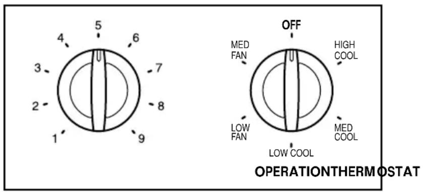
5 6 4 3 7 2 8 1 9 OFF MED FAN HIGH COOL LOW FAN MED COOL LOW COOL OPERATION THERM OSTAT■ OPERATION
High Cool, Med Cool and Low Cool provide cooling with different fan speeds. Med Fan or Low Fan provides air circulation and filtering without cooling. Off turns the air conditioner off.
NOTICE
: If you move the switch from a cool setting to off or to a fan setting, wait at least 3 minutes before switching back to a cool setting.
Cooling Descriptions
For Normal Cooling- Select High Cool or Med Cool with the Operation knob at the midpoint of Thermostat knob.
For Maximum Cooling- Select High Cool with the Operation knob at the highest number available on your Thermostat knob.
For Quieter & Nighttime Cooling- Select Low Cool with the Operation knob at the midpoint of Thermostat knob.
■ THERMOSTAT
The THERMOSTAT is used to maintain the room temperature. The compressor will cycle on and off to keep the room at the same level of comfort. When you turn the knob to a higher number(the right side) and the indoor air will become cooler.
The 5 or 6 position (the middle position of arc) is a normal setting for average conditions.
CAUTION
: When the air conditioner has been performed its cooling operation and is turned off or set to the fan position, wait at least 3 minutes before resetting to the cooling operation again.
Remote Control Operations
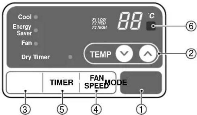
The remote control and control panel will look like those represented in the following pictures.
text_image
Cool Energy Saver Fan Dry Timer F1 LOW F2 MED F3 HIGH 88 °C TEMP TIMER FAN SPEED MODE ⑥ ② ③ ⑤ ④ ①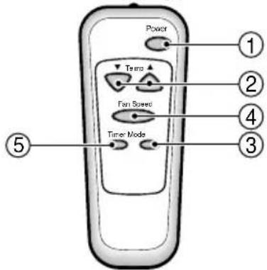
text_image
Power Temp Fan Speed Time Mode ① ② ④ ③ ⑤1 POWER
Operation starts when this button is pressed and stops when you press the button again.
2) TEMPERATURE CONTROL
The thermostat monitors room temperature to maintain the desired temperature.
The thermostat can be set between 16°C\~30°C.
The unit takes an average of 30 minutes to adjust the room temperature by 1°C.
Select cooling mode to cool the room.
Select energy saver mode for energy saving operation.
Select fan mode for basic ventilating fan operation.
Select dry mode for dry operation.
4 FAN SPEED SELECTOR
For increased power while cooling, select a higher fan speed.
3 steps: High → Low → Med
5 ON/OFF TIMER
The timer can be set to start and stop the unit in hourly increments (up to 12 hours).
6 REMOTE CONTROL SENSOR
AUTO RESTART
In failure of electric power, the unit runs as previous setting operation.
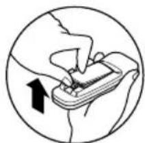
Inserting the Remote Control Batteries
1 Push out the cover on the back of the remote control with your thumb
2 Pay attention to polarity and insert two new AAA 1.5V batteries.
3 Reattach the cover.
NOTICE
: Do not use rechargeable batteries. Make sure that both batteries are new.
- In order to prevent discharge, remove the batteries from the remote control if the air conditioner is not going to be used for an extended period of time. Keep the remote control away from extremely hot or humid places.
To maintain optimal operation of the remote control, the remote sensor should not be exposed to direct sunlight.
- The remote control can be mounted on a wall using the mountable holder.
natural_image
Illustration of hands using a handheld device to interact (no text or symbols present)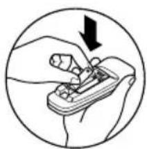
natural_image
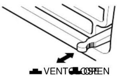
Illustration of a hand using a tool to adjust or install a component, enclosed in a circle (no text or symbols)Adjusting the Air Flow Direction
Vent Control
For maximum cooling efficiency, CLOSE the vent. This will allow internal air circulation.
OPENtheventtodischargestaleair.
text_image
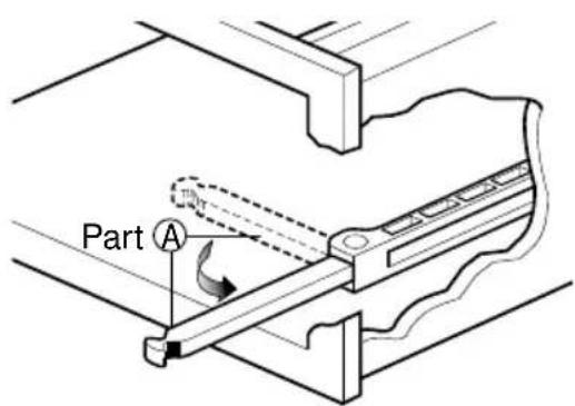
VENT OPENNOTICE
: Before using the ventilation feature, position the vent lever by pulling Part A out straight and snapping it into place.
text_image
Part A 100%Adjusting the Air Flow Direction
Airflow can be adjusted by changing the direction of the air conditioner's louvers. This can also increase the cooling efficiency of the air conditioner.
- Adjusting Horizontal Air Flow Direction
Adjusting the vertical louvers left and right will change horizontal airflow.
- Adjusting Vertical Air Flow Direction
Adjusting the horizontal vane up and down will change vertical airflow. The vane can be adjusted by nudging the vane backward or forward.
natural_image
Line drawing of a computer oven with ventilation grilles and a hand pointing to the lid (no text or symbols)Adjusting horizontal air flow
natural_image
Line drawing of a computer oven with a hand pointing to the lid (no text or symbols)Adjusting vertical air flow
• Recommended orientation of louvers
Adjust louvers to face upwards when cooling to maximize cooling efficiency.
Care and Maintenance
Turn the power off and unplug the power plug before cleaning the air conditioner.
Air Filter
The air filter behind the inlet grille should be checked and cleaned at least once every 2 weeks (or as necessary) to maintain optimal performance of the air conditioner.
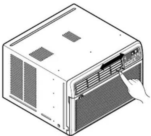
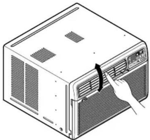
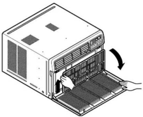
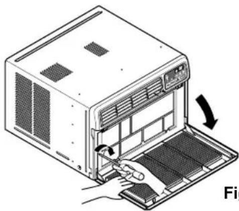
How to remove the air filter
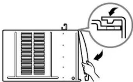
1 The grille may be opened from the top for easy maintenance after installation.
2 Open the inlet grille by pulling off the exposed door on the top of the unit (based on installation).
3 Pull the tab slightly to release the filter. Pull the filter in the same direction as the opening.
4 Clean the filter with warm, soapy water. The water should be below 40^ C ( 104^ F).
5 Rinse off and gently shake off excess water from the filter. Let it dry before replacing it.
natural_image
Illustration of a server rack with hand inserting a fan into the rack (no text or symbols)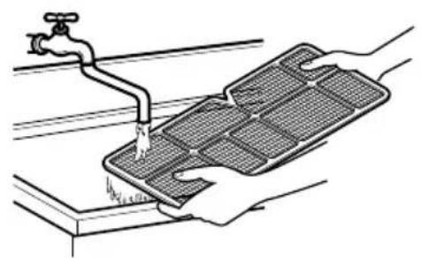
natural_image
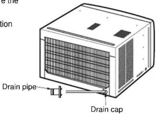
Illustration of hands cleaning a water tank with a faucet (no text or symbols)Drainage
The base pan may overflow due to high humidity. To drain the excess water, remove the drain cap from the back of the unit and secure the drainpipe.
When pressing the drainpipe into place, apply force in the direction away from the fins to avoid injuring yourself.
text_image
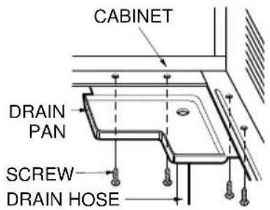
Drain pipe Drain capHow to Attach Drain Pan (Optional)
The air conditioner employs a proper drain method whereby the condensed water (moisture removed from the air) is drained to the outside.
In very humid weather, (and for reverse cycle models in the reverse mode) excessive condensate water removed from the air may cause some water to collect. To remove this excess water you can install the drain pan as detailed below.
1 Take the drain pan which is located in the air discharge.
2 Remove the hole rubber from the base-pan (for some models).
3 Install the drain pan to the right corner of the cabinet with 4 (or 2) screws.
4 Connect the drain hose of 3/5" inside diameter to the outlet located at the bottom of the drain pan. You can purchase the drain hose or tubing locally to satisfy your particular needs. (Drain hose is not supplied).
text_image
CABINET DRAIN PAN SCREW DRAIN HOSEHardware Installation
Remote Control Operations

CAUTION
: This appliance should be installed in accordance with national wiring regulations. The following information serves acts as a guide to help to explain product features.
text_image
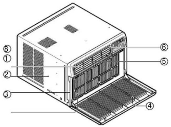
Labeled diagram of a microwave oven showing internal components and numbered parts- CABINET
- FRONT GRILLE
- AIR FILTER
- AIR INTAKE (INLET GRILLE)
- AIR DISCHARGE
- VERTICAL AIR DEFLECTOR (HORIZONTAL LOUVER)
- EVAPORATOR
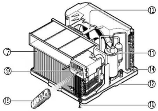
text_image
Labeled diagram of an electronic device showing internal components and numbered parts- HORIZONTAL AIR DEFLECTOR (VERTICAL LOUVER)
- CONTROL PANEL
- POWER CORD
- COMPRESSOR
- BASE PAN
- BRACE
- CONDENSER
- REMOTE CONTROLLER(OPTIONAL)
Installing the Power cord
You can choose between two methods below according to your window stool shape and preference.
Using slit "A"
- Fasten the stopper using 2 screw holes, and lead out the power cord through slit "A".
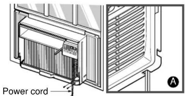
text_image
Power cord AUsing slit "B"
- Fasten the stopper using left screw hole, and rotate properly to lead the power cord out through slit "B".
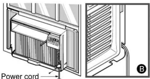
text_image
Power cord BWK Series
How to Install the Unit
1 To prevent vibration and noise, make sure the unit is installed securely and firmly.
2 Install the unit where the sunlight does not shine directly on the unit.
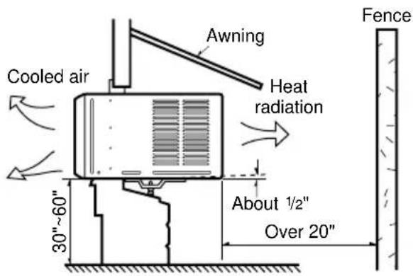
3 The outside of the cabinet must extend outward for at least 12" and there should be no obstacles, such as a fence or wall, within 20" from the back of the cabinet because it will prevent heat radiation of the condenser.
Restriction of outside air will greatly reduce the cooling efficiency of the air conditioner.
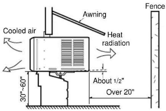
text_image
Cooled air Awning Heat radiation 30"~60" About 1/2" Over 20" FenceCAUTION
: All side louvers of the cabinet must remain exposed to the outside of the structure.
4 Install the unit a little slanted so the back is slightly lower than the front (about 1/2"). This will force condensed water to flow to the outside.
5 Install the unit with the bottom about 30"\~60" above the floor level.
Window Requirements
NOTICE
: All supporting parts should be secured to firm wood, masonry, or metal.
- This unit is designed for installation in standard double hung windows with actual opening widths from 23" to 36".
- The top and bottom window sash must open sufficiently to allow a clear vertical opening of 15" from the bottom of the upper sash to the window stool.
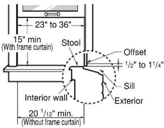
text_image
23" to 36" 15" min (With frame curtain) Stool Offset 1/2" to 11/4" Sill Exterior Interior wall 20 1/12" min. (Without frame curtain)WL Series
How to Install the Unit
1 To prevent vibration and noise, make sure the unit is installed securely and firmly.
2 Install the unit where the sunlight does not shine directly on the unit.
3 The outside of the cabinet must extend outward for at least 12" and there should be no obstacles, such as a fence or wall, within 20" from the back of the cabinet because it will prevent heat radiation of the condenser.
Restriction of outside air will greatly reduce the cooling efficiency of the air conditioner.
text_image
Cooled air Awning Heat radiation 30"~60" About 1/2" Over 20" FenceCAUTION
: All side louvers of the cabinet must remain exposed to the outside of the structure.
4 Install the unit a little slanted so the back is slightly lower than the front (about 1/2"). This will force condensed water to flow to the outside.
5 Install the unit with the bottom about 30"\~60" above the floor level.
Window Requirements
NOTICE
: All supporting parts should be secured to firm wood, masonry, or metal.
- This unit is designed for installation in standard double hung windows with actual opening widths from 27" to 39".
- The top and bottom window sash must open sufficiently to allow a clear vertical opening of 16" from the bottom of the upper sash to the window stool.
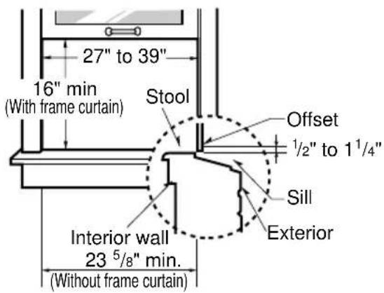
text_image
27" to 39" 16" min (With frame curtain) Stool Offset ½" to 1¼" Sill Exterior Interior wall 23 ⁵/8" min. (Without frame curtain)WP Series
How to Install the Unit
1 To prevent vibration and noise, make sure the unit is installed securely and firmly.
2 Install the unit where the sunlight does not shine directly on the unit.
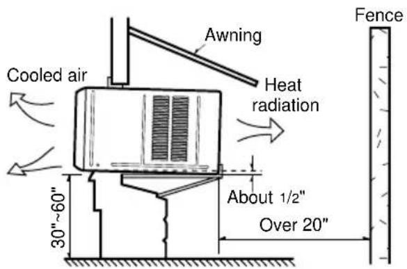
3 There should be no obstacles, such as a fence and wall, within 20" from the back of the cabinet because it will prevent heat radiation of the condenser.
Restriction of outside air will greatly reduce the cooling efficiency of the air conditioner.
text_image
Cooled air 30"~60" Awning Heat radiation About 1/2" Over 20" FenceCAUTION
: All side louvers of the cabinet must remain exposed to the outside of the structure.
4 Install the unit a little slanted so the back is slightly lower than the front (about 1/2"). This will force condensed water to flow to the outside.
5 Install the unit with the bottom about 30"\~60" above the floor level.
Window Requirements
NOTICE
: All supporting parts should be secured to firm wood, masonry, or metal.
- This unit is designed for installation in standard double hung windows with actual opening widths from 29" to 41".
- The top and bottom window sash must open sufficiently to allow a clear vertical opening of 18" from the bottom of the upper sash to the window stool.
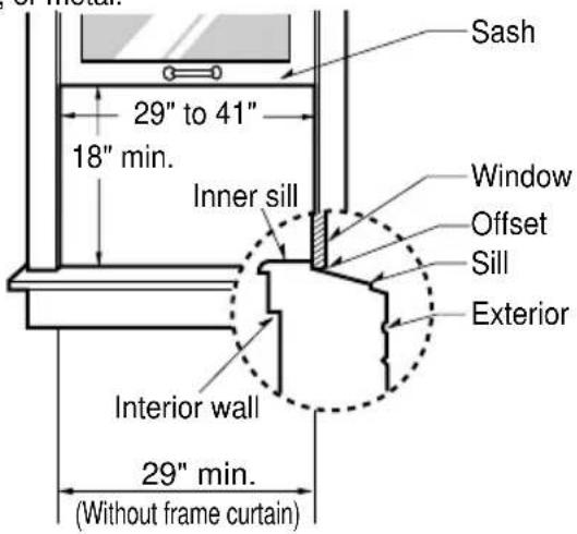
text_image
Sash 29" to 41" 18" min. Inner sill Window Offset Sill Exterior Interior wall 29" min. (Without frame curtain)WK, WL Series
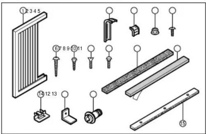
Installation Kits Contents
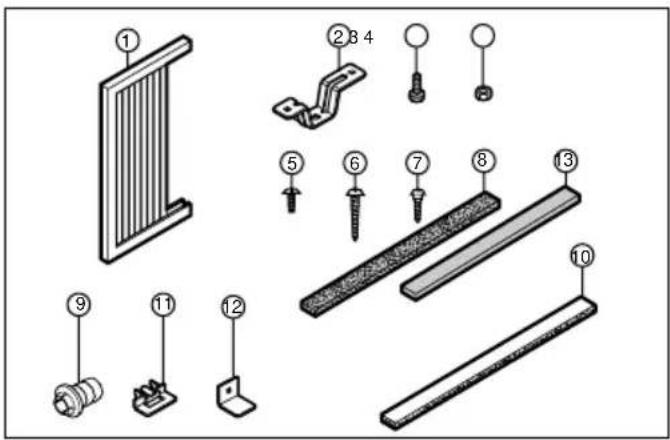
text_image
Exploded view diagram of a mechanical assembly with numbered parts for identification| NO. | NAME OF PARTS Q'TY | ||||
| 1 | FRAME CURTAIN 2 | ||||
| 2 | SILL SUPPORT 2 | ||||
| 3 | B | O | L | T | 2 |
| 4 | N | U | T | 2 | |
| 5 | SCREW (TYPE A) 16 | ||||
| 6 | SCREW (TYPE B) 3 | ||||
| 7 | SCREW (TYPE C) 5 | ||||
| 8 | F | O | A | M | - S |
| 9 | D | R | A | I | N P |
| 10 | FOAM-PE | 1 | |||
| 11 | FRAME GUIDE | 2 | |||
| 12 | WINDOW LOCKING BRACKET | 1 | |||
| 13 | FOAM-PE | 1 | |||
Suggested Tool Requirements
SCREWDRIVER(Philips and Flatead), RULER, KNIFE, HAMMER, PENCIL, LEVEL
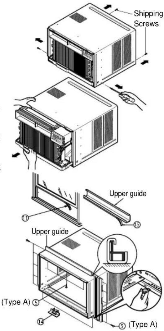
PREPARATION OF CHASSIS
1 Remove the screws which fasten the cabinet at both sides and at the back.
2 Slide the unit from the cabinet by gripping the base pan handle and pulling forward while bracing the cabinet.
3 Cut the window sash seal to the proper length. Peel off the backing and attach the Foam-PE ⑬ to the underside of the window sash.
4 Remove the backing from the top upper guide Foam-PE ⑩ and attach it to the bottom of the Upper Guide.
5 Attach the upper guide onto the top of the cabinet with 3 Type A screws ⑤.
6 Insert the Frame Guides ⑪ into the bottom of the cabinet.
⑦ Insert the Frame Curtain ① into the Upper Guide and Frame Guides ⑪
8 Fasten the curtains to the unit with 4 Type A screws ⑤.
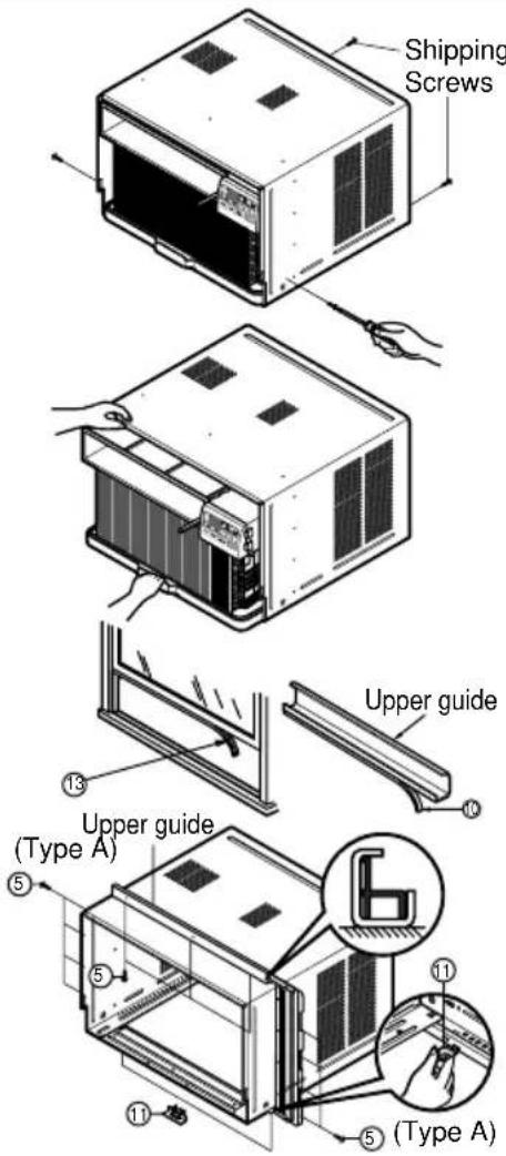
text_image
Shipping Screws Upper guide ⑬ ⑭ ⑮ ⑯ ⑰ ⑱ ⑲ ⑳ ⑴ ⑵ ⑶ ⑷ ⑧ Type ACabinet Installation
1 Open the window. Mark a line on center of the window stool.
Carefully place the cabinet on the window stool and align the center mark on the bottom front with the center line marked in the window stool.
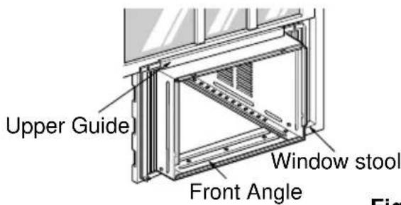
text_image
Upper Guide Window stool Front AngleFig. 1
2 Pull the bottom window sash down behind the Upper Guide until it meets.
NOTICE
: Do not pull the window sash down tightly that the movement of Frame Curtain ① is restricted.
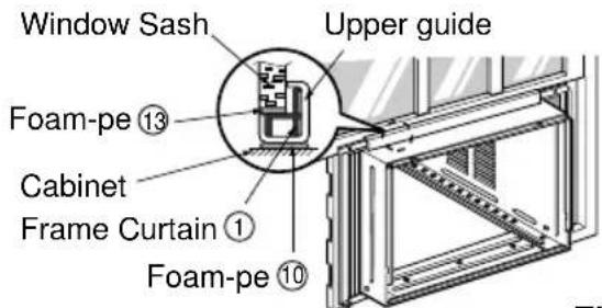
text_image
Window Sash Upper guide Foam-pe ⑬ Cabinet Frame Curtain ① Foam-pe ⑩Fig. 2
3 Loosely assemble the Sill Support ② using the parts in Fig. 3.
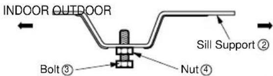
text_image
INDOOR OUTDOOR Sill Support ② Bolt ③ Nut ④Fig. 3
4 Select the position that will place the Sill Support ② near the outer most point on sill (See Fig. 4)
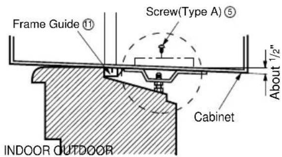
text_image
Frame Guide ⑪ Screw(Type A) ⑤ Cabinet About 1/2" INDOOR OUTDOORFig. 4
NOTICE
: Be careful when you install the cabinet (Frame Guides ⑪ are broken easily).
5 Attach the Sill Support ② to the cabinet track hole in relation to the selected position using 2 Type A screws in each support (See Fig. 4).
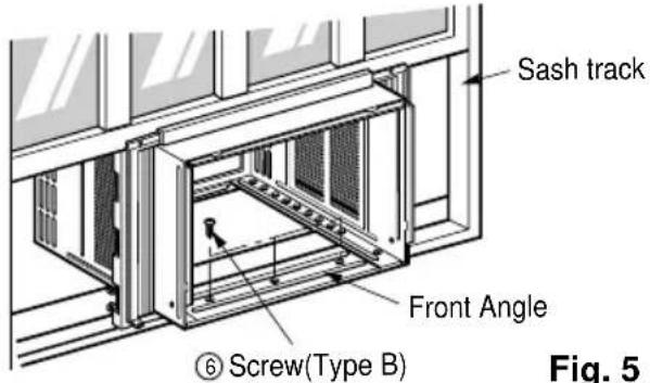
6 The cabinet should be installed with a very slight tilt (about 1/2") downward toward the outside (See Fig. 5).
Adjust the bolt and the nut of Sill Support ② for balancing the cabinet.
7 Attach the cabinet to the window stool by driving the screws ⑥ (Type B: Length 16mm (5/8 inch) and below.) through the front angle into window stool.
8 Pull each Frame Curtain ① fully to each window sash track, and repeat step 2.
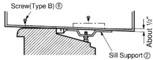
text_image
Screw(Type B) ⑥ About 1/2" Sill Support ②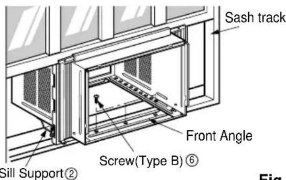
text_image
Sash track Front Angle Screw(Type B) ⑥ Sill Support② FigFig. 5
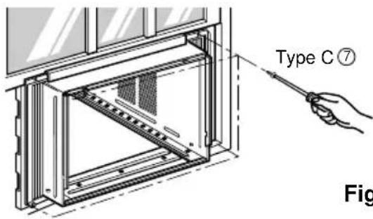
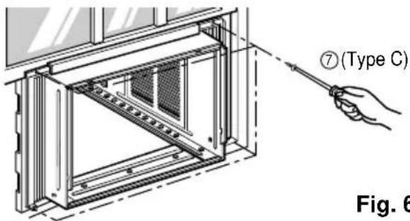
9 Attach each Frame Curtain ① the window sash using screws ⑦ (Type C). (See Fig. 6)
CAUTION
: Donotdrillahole in the bottom pan. The unit is designed to operate with approximately 1/2" of water in bottom pan. There is no need to add water if the pan is dry.
text_image
Type C⑦ FigFig. 6
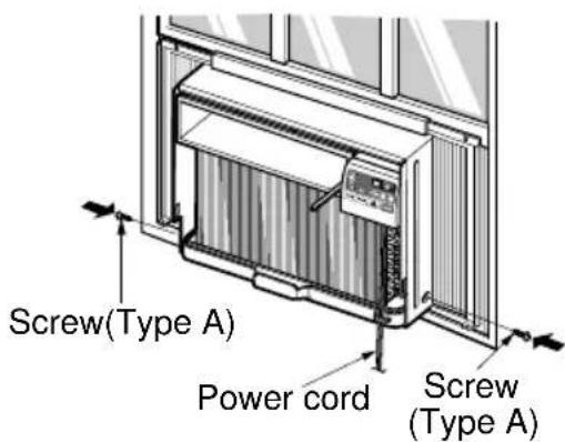
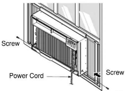
10 Slide the unit into the cabinet. (See Fig. 7)
CAUTION
: For security purpose, reinstall screws (Type A) at cabinet's sides.
text_image
Screw(Type A) Power cord Screw (Type A)Fig. 7
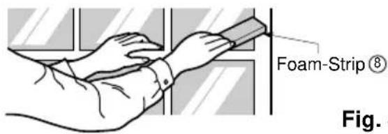
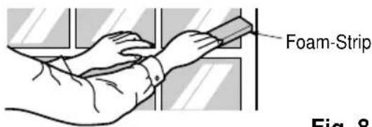
11 Cut the Foam-Strip ⑧ to the proper length and insert between the upper window sash and the lower window sash. (See Fig. 8)
text_image
Foam-Strip ⑧ Fig. 8Fig. 8
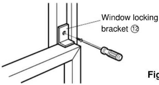
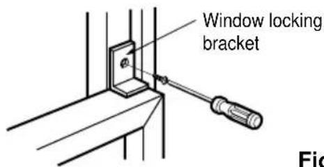
12 Attach the Window Locking Bracket ⑫ with a Type C screw ⑦ See Fig. 9)
text_image
Window locking bracket ⑫ FigFig. 9
13 Attach the front grille to the cabinet by inserting the tabsonthe grille into the tabsonthe front cabinet. Push the grille in until it snaps into place. (See Fig. 10)
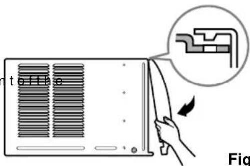
text_image
toff e FigFig. 10
14 Pull down the inlet grille and secure it with a Type A screw ⑤ through the front grille. (See Fig. 11)
15 Window installation of room air conditioner is now completed. See ELECTRICAL DATA for attaching power cord to electrical outlet.
natural_image
Illustration of a computer unit with a hand inserting a screwdriver into the rack (no text or symbols visible)Fig. 11
WP Series
Installation Kits Contents
text_image
1 2 3 4 5 6 7 8 9 10 11 14 12 13 15| NO. NAME OF PARTS Q'TY | |
| 1 FRAME CURTAIN 2 | |
| 2 SUPPORT BRACKET | 2 |
| 3 SILL BRACKET | 2 |
| 4 LOCK NUT 4 | |
| 5 SCREW (TYPE A) | 14 |
| 6 SCREW (TYPE B) 7 | |
| 7 SCREW (TYPE C) | 5 |
| 8 SCREW (TYPE D) | 2 |
| 9 CARRIAGE BOLT | 2 |
| 10 FOAM STRIP | 1 |
| 11 FOAM SEAL | 1 |
| 12 WINDOW LOCKING BRACKET | 1 |
| 13 DRAIN PIPE | 1 |
| 14 FRAME GUIDE | 2 |
| 15 FOAM-PE | 1 |
Suggested Tool Requirements
SCREWDRIVER(Philips and Flatead), RULER, KNIFE, HAMMER, PENCIL, LEVEL
PREPARATION OF CHASSIS
1 Remove the screws which fasten the cabinet at both sides and at the back.
2 Slide the unit from the cabinet by gripping the base pan handle and pulling forward while bracing the cabinet.
3 Cut the window sash seal to the proper length. Peel off the backing and attach the Foam-Seal ⑪ to the underside of the window sash.
4 Remove the backing from the top upper guide Foam-PE ⑮ and attach it to the bottom of the Upper Guide.
5 Attach the upper guide onto the top of the cabinet with 3 Type A screws ⑤.
6 Insert the Frame Guides ⑭ into the bottom of the cabinet.
⑦ Insert the Frame Curtain ① into the Upper Guide and Frame Guides ⑭
8 Fasten the curtains to the unit with 10 Type A screws ⑤.
text_image
Shipping Screws Upper guide Upper guide (Type A) ⑤ ⑤ (Type A)Cabinet Installation
1 Open the window. Mark a line on the center of the window stool between the side window stop moldings.
Loosely attach the sill bracket to the support bracket using the carriage bolt and the lock nut.
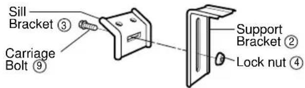
text_image
Sill Bracket ③ Carriage Bolt ⑨ Support Bracket ② Lock nut ④Fig. 1
2 Attach the sill bracket to the window sill using the screws (Type B).
Carefully place the cabinet on the window stool and align the center mark on the bottom front with the center line marked window stool.
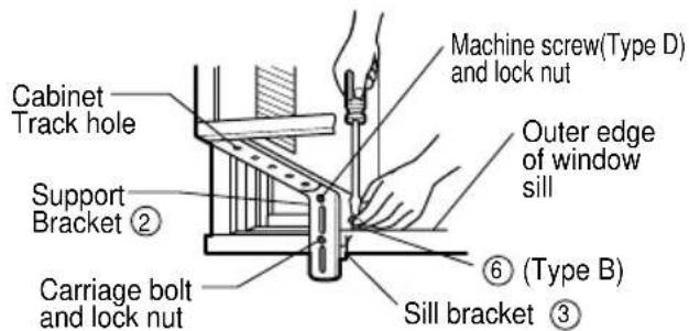
text_image
Cabinet Track hole Support Bracket ② Carriage bolt and lock nut Machine screw(Type D) and lock nut Outer edge of window sill ⑥ (Type B) Sill bracket ③Fig. 2
3 Using the M-screw and the lock nut, attach the support bracket to the cabinet track hole. Use the first track hole after the sill bracket on the outer edge of the window sill. Tighten the carriage bolt and the lock nut. Be sure the cabinet slants outward.
CAUTION
: Do not drill a hole in the bottom pan. The unit is designed to operate with approximately 1/2" of water in bottom pan.
text_image
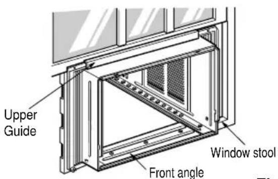
Upper Guide Window stool Front angleFig. 3
4 Pull the bottom window sash down behind the Top retainer bar until they meet.
NOTICE
-
Do not pull the window sash down so tightly that the movement of Frame curtain is restricted. Attach the cabinet to the window stool by driving the screws (Type B) through the cabinet into window stool.
-
The cabinet should be installed with a very slight tilt downward toward the outside.
text_image
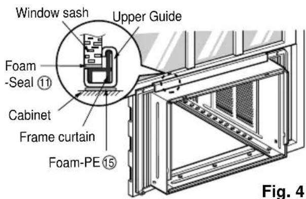
Window sash Upper Guide Foam -Seal ⑪ Cabinet Frame curtain Foam-PE ⑮ Fig. 45 Pull each Frame curtain fully to each window sash track, and pull the bottom window sash down behind the Top retainer bar until it meets.
text_image
Sash track Front Angle ⑥ Screw(Type B) Fig. 5Fig. 5
6 Attach each Frame curtain the window sash by using screws (Type C.) (See Fig. 6)
text_image
⑦(Type C) Fig. 67 Slide the unit into the cabinet.(See Fig. 7)
CAUTION
:For security purpose, reinstall screws(Type A) at cabinet's sides.
text_image
Screw Power Cord ScrewFig. 7
8 Cut the Foam-strip to the proper length and insert between the upper window sash and the lower window sash.(See Fig. 8)
text_image
Foam-Strip Fig. 8Fig. 8
9 Attach the Window locking bracket with a screw (Type C.) (See Fig. 9)
text_image
Window locking bracket FicFig. 9
10 Attach the front grille to the cabinet by inserting the tabs on the grille into the tabs on the front of the cabinet. Push the grille in until it snaps into place. (See Fig.10)
11 Lift the inlet grille and secure it with a screw (Type A) through the front grille.(See Fig. 10)
12 Window installation of room air conditioner is now completed. See ELECTRICAL DATA for attaching power cord to electrical outlet.
text_image
Diagram showing a hand holding a cable with a magnified inset illustrating airflow or heat transfer in a heating unit.
natural_image
Illustration of a computer oven with a hand inserting a component into the rack (no text or symbols visible)Fig. 10
Electrical Safety
Electrical Data
NOTICE
The shape may be different according to its model.
| Use Wall Receptacle Power | Supply |
 Standard 125V, 3-wire grounding receptacle rated 15A, 125V AC Standard 125V, 3-wire grounding receptacle rated 15A, 125V AC | Use 15 AMP. time delay fuse or 15 AMP. circuit breaker. |
 Standard 250V, 3-wire grounding receptacle rated 15A, 250V AC Standard 250V, 3-wire grounding receptacle rated 15A, 250V AC | |
 Standard 250V, 3-wire grounding receptacle rated 20A, 250V AC Standard 250V, 3-wire grounding receptacle rated 20A, 250V AC | Use 20 AMP. time delay fuse or 20 AMP. circuit breaker. |
NOTICE
DO NOT USE AN EXTENSION CORD on 230, 208, and 230/208 Volt units.
All wiring should be made in accordance with local electrical codes and regulations.
Aluminum house wiring may pose special problems. Consult a qualified electrician.
Electrical Safety
IMPORTANT
(PLEASE READ CAREFULLY)
FOR THE USER'S PERSONAL SAFETY, THIS APPLIANCE MUST BE PROPERLY GROUNDED
The power cord of this appliance is equipped with a three-prong (grounding) plug. Use this with a standard three-slot (grounding) wall power outlet to minimize the hazard of electric shock. The customer should have the wall receptacle and circuit checked by a qualified electrician to make sure the receptacle is properly grounded.
DO NOT CUT OR REMOVE THE THIRD (GROUND) PRONG FROM THE POWER PLUG.
A. SITUATIONS WHEN THE APPLIANCE WILL BE DISCONNECTED OCCASIONALLY:
Because of potential safety hazards, we strongly discourage the use of an adapter plug. However, if you wish to use an adapter, a TEMPORARY CONNECTION may be made. Use UL-listed adapter, available from most local hardware stores. The large slot in the adapter must be aligned with the large slot in the receptacle to assure a proper polarity connection.
CAUTION
: Attaching the adapter ground terminal to the wall receptacle cover screw does not ground the appliance unless the cover screw is metal, and not insulated, and the wall receptacle is grounded through the house wiring. The customer should have the circuit checked by a qualified electrician to make sure the receptacle is properly grounded.
Disconnect the power cord from the adapter, using one hand on each. Otherwise, the adapter ground terminal might break. DO NOT USE the appliance with a broken adapter plug.
B. SITUATIONS WHEN THE APPLIANCE WILL BE DISCONNECTED OFTEN.
Do not use an adapter plug in these situations. Unplugging the power cord frequently can lead to an eventual breakage of the ground terminal. The wall power outlet should be replaced by a three-slot (grounding) outlet instead.
USE OF EXTENSION CORDS
Because of potential safety hazards, we strongly discourage the use of an extension cord. However, if you wish to use an extension cord, use a CSA certified/UL-listed 3-wire (grounding) extension cord, rated at 15A, 125V.
Common Problems and Solution
Before calling for service, please review the following list of common problems and solutions.
The air conditioner is operating normally when:
- You hear a pinging noise. This is caused by water being picked up by the condenser on rainy days or in highly humid conditions. This feature is designed to help remove moisture in the air and improve cooling efficiency.
- You hear the thermostat click. This is caused by the compressor cycle starting and stopping.
- You see water dripping from the rear of the unit. Water may be collected in the base pan in highly humid conditions or on rainy days. This water overflows and drips from the rear of the unit.
- You hear the fan running while the compressor is silent. This is a normal operational feature.
The air conditioner may be operating abnormally when:
| Problem Possible Causes What To Do | ||
| The air conditioner does not operate at all | ■ The air conditioner is unplugged or not plugged in completely | · Make sure the plug is completely plugged into the outlet |
| ■ The fuse is blown/circuit breaker is triggered | · Check the fuse/circuit breaker box and replace the fuse or reset the breaker | |
| ■ Power failure. | · In the event of a power failure, set the power control to OFF. When the power is restored, wait 3 minutes to restart the air conditioner to prevent the compressor from overloading | |
| Air conditioner does not cool | ■ Air flow is restricted | · Make sure there are no curtains, blinds, furniture or other obstacles in front of the air conditioner |
| ■ The THERMOSTAT may not be set cool enough | · Turn the knob to a higher setting. The highest setting provides maximum cooling | |
| ■ The air filter is dirty. | · Clean the filter at least every 2 weeks. Refer to the “Care and Maintenance” section (p.11) of the manual. | |
| ■ The air conditioner was just turned on. | · After the air conditioner is turned on, you need to give the air conditioner some time to cool the room. | |
| ■ Cold air is escaping. | · Check for open furnace floor resisters and cold air returns.· CLOSE the air conditioner vent | |
| ■ Cooling coils are iced up | · See Ice appears on the air conditioner below | |
| Ice appears on the air conditioner. | ■ The cooling coils are iced | · Ice may block the air flow and obstruct the air conditioner from properly cooling the room. Set the fan at MED or HIGH while setting the thermostat at 1 or 2 until the ice melts. |
TABLE DES MATIERES
Précautions....3
Mode d'emploi....8
natural_image
Simple line drawing of a family enjoying a round table with drinks and snacks, surrounded by palm trees (no text or symbols)Précautions
natural_image
Illustration of a person inside an air conditioner unit with a warning symbol (no text or labels)text_image
Diagram showing a hand holding an air conditioner next to a power outlet, with a prohibition symbol indicating no protection.natural_image
Cartoon illustration of a person reacting to a computer screen with a 'no' symbol (no text or labels)■ Fonctionnement
text_image
Illustration showing a cartoon car with a warning sign and an electrical plug, indicating electric shock hazard.text_image
Safety warning illustration showing a cartoon car with a 'No' symbol and an electrical plug connected to it.natural_image
Illustration of a cartoon-style computer with a face and open mouth, and a crossed-out plug with a prohibition symbol (no text or labels)natural_image
Illustration of a car with a smiling face inside and a document character holding a checkmark (no text or symbols present)natural_image
Illustration of a person using an electrical outlet to clean a damaged air conditioner, with smoke and warning symbol (no text or labels)text_image
Illustration showing a cartoon electric plug connected to a fuse with a prohibition symbol, accompanied by wings and lightning.text_image
Safety warning illustration showing a hand holding an air conditioner next to a prohibition symbol and a person using a device.natural_image
Illustration of a person inside an air conditioner unit with a prohibition symbol above (no text or labels)natural_image
Illustration of a person exiting a door with an exclamation mark (no text or symbols on the diagram itself)natural_image
Illustration of a person opening a refrigerator with a warning symbol (no text or labels present)
PRECAUTION
■ Installation
natural_image
Illustration of a person installing or adjusting a solar panel with a child inside (no text or symbols)natural_image
Illustration of stacked boxes with a prohibition symbol above, next to an air conditioner unit (no text or symbols on boxes)natural_image
Cartoon illustration of a distressed air conditioner unit with arms and exhaust lines, no text or symbols present■ Fonctionnement
text_image
Illustration showing a plug being charged with a warning symbol, indicating electrical hazard or alert.text_image
Illustration showing a person with a 'BUY' sign, a cartoon car, and an exclamation mark, alongside a person carrying bags.text_image
Diagram showing a device connected to an office chair with a prohibition symbol, indicating no liability or prohibition of the device.text_image
Illustration showing a cartoon character reacting to a computer with a warning symbol, while a person is talking on the phone.text_image
Illustration showing a cigarette stopper, a hand holding a cigarette, and a person holding a smoking can with a no-smoking symbol.text_image
Illustration showing a person using a tool to interact with a device, with speech bubble and warning symbol nearbynatural_image
Illustration of a person standing beside a box with hands reaching toward it, next to a prohibition symbol (no text or labels)natural_image
Illustration of a person inside an air conditioner unit with a sleeping face and a prohibition sign (no text or symbols)natural_image
Illustration of a person using a solar panel to interact with a server or computer (no text or symbols present)text_image
Illustration showing a prohibition symbol next to a box and two cartoon characters labeled 'Wax' and 'Thinner'.text_image
Illustration showing a person reacting to three different air conditioners: a distressed refrigerator, a distressed refrigerator with angry expression, and a prohibited sign.natural_image
Illustration of hands using a handheld device to interact (no text or symbols present)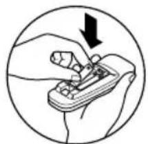
natural_image
Illustration of a hand using a tool to adjust or install a component, with a black arrow indicating the direction (no text or symbols present)natural_image
Line drawing of a computer oven with ventilation grilles and a hand inserting a button (no text or symbols)natural_image
Illustration of a computer oven with a hand pointing to the lid panel (no text or symbols visible)natural_image
Illustration of a server rack with hand inserting a fan into the rack (no text or symbols)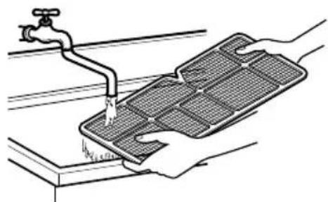
natural_image
Illustration of hands cleaning a tiled surface with a faucet (no text or symbols)Drainage
text_image
Labeled diagram of a microwave oven showing internal components and numbered parts- BOÎTIER
- GRILLE AVANT
- FILTRE À AIR
- PRISE D'AIRAIR (GRILLE DE PRISE D'AIR)
- RETOUR D'AIR
- DÉFLECTEUR D'AIR VERTICAL (VOLET HORIZONTAL).
- ÉVAPORATEUR
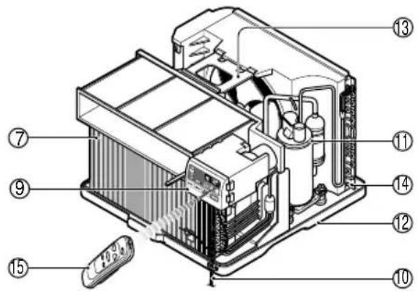
text_image
Exploded view diagram of a refrigerator internal components with numbered labels- DÉFLECTEUR D'AIR HORIZONTAL (VOLET VERTICAL)
- PANNEAU DE COMMANDE
- CORDON D'ALIMENTATION
- COMPRESSEUR
- RÉCEPTACLE D'EAU
- ÉQUERRE DE RENFORT
- CONDENSEUR
- TÉLÉCOMMANDE(FACULTATIF)
text_image
Exploded view diagram of a mechanical assembly with numbered parts for identification| NO. | NOM DES PIÈCES | QTÉ | ||||||
| 1 | VOLET D'ÉTANCHÉITÉ | 2 | ||||||
| 2 SUPPORT DE SEUIL 2 | ||||||||
| 3 | B | O | U | L | O | N | 2 | |
| 4 ÉCROU 2 | ||||||||
| 5 | V | I | S | ( | T | Y | P | E A |
| 6 | V | I | S | ( | T | Y | P | E B |
| 7 | V | I | S | ( | T | Y | P | E C |
| 8 BANDE EN MOUSSE | 1 | |||||||
| 9 TUYAU DE DRAINAGE | 1 | |||||||
| 10 | JOINT D'ÉTANCHÉITÉ EN MOUSSE | 1 | ||||||
| 11 | DISPOSITIF DE GUIDAGE DU CADRE | 2 | ||||||
| 12 | ÉTRIER DE VERROUILLAGE DE FENÊTRE | 1 | ||||||
| 13 | JOINT D'ÉTANCHÉITÉ EN MOUSSE | 1 | ||||||
Outils recommandés
TOURNEVIS (Philips etT Flatead), RÈGLE, COUTEAU, MARTEAU, CRAYON, NIVEAU.
PRÉPARATION DU CADRE
text_image
Type C⑦ FigFig. 6
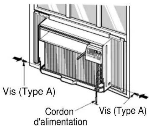
text_image
Vis (Type A) Cordon d'alimentation Vis (Type A)Fig. 7
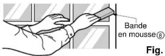
text_image
Bande en mousse® Fig.Fig. 8
natural_image
Illustration of a computer monitor with a hand holding a cable, showing internal circuitry (no text or symbols)Fig. 10
natural_image
Illustration of a computer unit with a hand inserting a cable into the rack (no text or symbols visible)Fig. 11
WP Feuilleton
text_image
Exploded view diagram of a mechanical assembly with numbered parts for identification| NO. | NOM DES PIÈCES | QTÉ |
| 1 | VOLET D'ÉTANCHÉITÉ | 2 |
| 2 | SUPPORT DE FIXATION | 2 |
| 3 | SUPPORT DE L'APPUI-FENÊTRE | 2 |
| 4 | ÉCROU | 4 |
| 5 | VIS (TYPE A) | 14 |
| 6 | VIS (TYPE B) | 7 |
| 7 | VIS (TYPE C) | 5 |
| 8 | VIS (TYPE D) | 2 |
| 9 | BOULON DE TRANSPORT | 2 |
| 10 BANDE EN MOUSSE | 1 | |
| 11 | JOINT D'ÉTANCHÉITÉ EN MOUSSE | 1 |
| 12 | ÉTRIER DE VERROUILLAGE DE FENÊTRE | 1 |
| 13 | TUYAU D'ÉCOULEMENT | 1 |
| 14 | DISPOSITIF DE GUIDAGE DU CADRE | 2 |
| 15 | JOINT D'ÉTANCHÉITÉ EN MOUSSE | 1 |
Outils recommandés
TOURNEVIS (Philips etT Flatead), RÈGLE, COUTEAU, MARTEAU, CRAYON, NIVEAU.
PRÉPARATION DU CADRE
text_image
Diagram showing a hand holding a cable with a magnified inset illustrating electrical circuit components.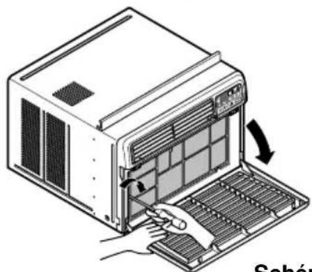
natural_image
Illustration of a computer with a hand inserting a grid into a rack (no text or symbols visible)Schéma. 10
Sécurité électrique
Données électriques
REMARQUE
Should your product prove to be defective in materials or workmanship under normal use during the warranty period listed below, which warranty period runs from the original date of purchase, LG Electronics will, at its option, repair or replace the product at no charge to you.
The warranty is valid only to the original purchaser of the product, during the warranty period, as long as it is in Canada.
GoldStar Room Air Conditioner Warranty Period
Components Parts Labor
All Parts 1 Years 1 Years (In-Home Service)
Compressor 5 Years 1 Years (In-Home Service)
No other warranty is applicable to this product. THE DURATION OF ANY IMPLIED WARRANTIES, INCLUDING THE IMPLIED WARRANTY OF MERCHANTABILITY, IS LIMITED TO THE DURATION OF THE EXPRESS WARRANTY HEREIN. LG ELECTRONICS SHALL NOT BE LIABLE FOR THE LOSS OF USE OF THE PRODUCT, INCONVENIENCE, LOSS OR ANY OTHER DAMAGES, DIRECT OR CONSEQUENTIAL, ARISING OUT OF THE USE OF OR INABILITY TO USE, THIS PRODUCT OR FOR ANY BREACH OF ANY EXPRESS OR IMPLIED WARRANTY, INCLUDING THE IMPLIED WARRANTY OF MERCHANTABILITY OR FITNESS FOR A PARTICULAR PURPOSE, APPLICABLE TO THIS PRODUCT.
Some Provinces or Territories do not allow for the exclusion or limitation of incidental or consequential damages of limitations on how long an implied warranty lasts; so these limitations or exclusions may not apply to you.
This warranty gives you, (the original purchaser) specific legal rights and you may also have other rights, which vary from province to province or territory to territory.
THE ABOVE WARRANTY DOES NOT APPLY TO:
- Service trips to your home to deliver and pickup, install, instruct or replace house fuses, or connect house wiring or plumbing, or correction of unauthorized repairs.
- Damage to the product caused by accident, pest, fire, floods or acts of God.
- Repairs when your GoldStar product is used in other that normal, single-family household use or contrary to the instructions outlined in the product's owners manual.
- Damage resulting from accident, alteration, misuse, abuse, or improper installation or maintenance.
- Products with altered or removed serial numbers.
If the product is installed outside the normal service area, any cost of transportation involved in the repair of the product, or the replacement of a defective part, shall be borne by you (the owner).
CUSTOMER ASSISTANCE INFORMATION:
| To obtain Warranty Coverage: | Retain your Bill of Sale to prove the date of purchase.A copy of your Sales Receipt must be submitted when warranty service is provided.This warranty is invalid if the factory applied serial number has been altered or removed from the product. |
| To obtain Product or Customer Service Assistance: | Call 1-888-LG-CANADA (542 2623)Press the appropriate menu option, and have your product model and serial numbers and your postal code ready. |
| To obtain the nearest Authorized Service Center: | Access our web-site at: www.LG.ca (Service Option) or Call 1-888-LG-CANADA (542 2623)Press the appropriate menu option, have your product model & serial numbers & your postal code ready. |