UU240R - Saw METABO - Free user manual and instructions
Find the device manual for free UU240R METABO in PDF.
User questions about UU240R METABO
0 question about this device. Answer the ones you know or ask your own.
Ask a new question about this device
Download the instructions for your Saw in PDF format for free! Find your manual UU240R - METABO and take your electronic device back in hand. On this page are published all the documents necessary for the use of your device. UU240R by METABO.
USER MANUAL UU240R METABO
SAFETY INSTRUCTIONS AND INSTRUCTION MANUAL
Failure to follow these rules may result in serious personal injury.
To reduce the risk of injury, keep both hands on stand handles when raising and lowering the stand.
Before folding the stand, miter saw MUST be removed from the stand.
Use only with metabo HPT mounting brackets. Mounting brackets offered by other than metabo HPT have not been tested with this stand and use of them could be hazardous. Please read and understand this entire manual before attempting to assemble, operate or install the product. These safety instructions are not meant to cover every possible condition that could occur.
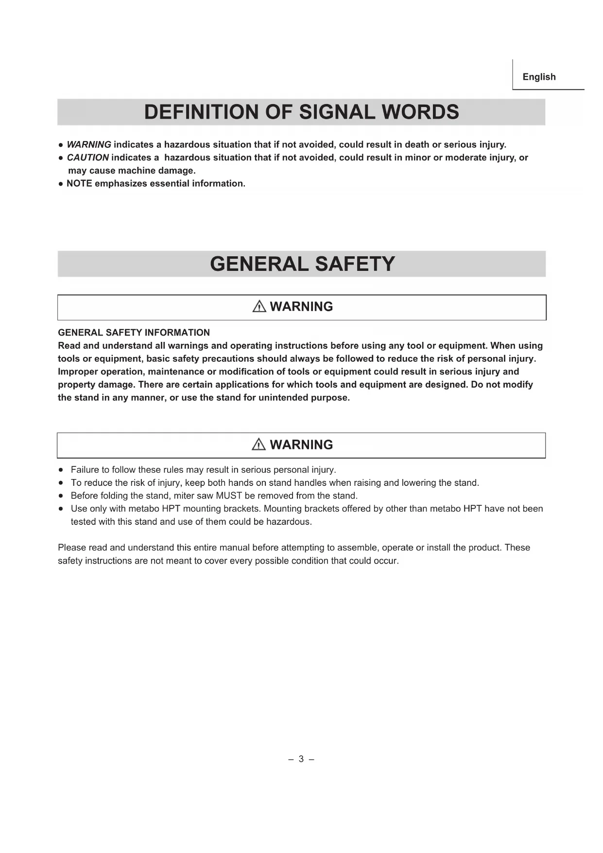
DEFINITION OF SIGNAL WORDS
● WARNING indicates a hazardous situation that if not avoided, could result in death or serious injury. ● CAUTION indicates a hazardous situation that if not avoided, could result in minor or moderate injury, or may cause machine damage. ● NOTE emphasizes essential information.
GENERAL SAFETY INFORMATION
Read and understand all warnings and operating instructions before using any tool or equipment. When using tools or equipment, basic safety precautions should always be followed to reduce the risk of personal injury. Improper operation, maintenance or modication of tools or equipment could result in serious injury and property damage. There are certain applications for which tools and equipment are designed. Do not modify the stand in any manner, or use the stand for unintended purpose.– 4 – English
Keep children away. All visitors should be kept at a safe distance from the work area. ● Always keep work area clean. Cluttered areas and benches invite accidents.
Before you use the stand, make sure no parts of the stand are damaged or deformed.
Before you use the stand, make sure all the parts or components of the stand are properly installed.
Do not use in dangerous environment. Do not use the stand in damp or wet locations, or expose them to rain. Keep work area well lighted. ● Always use the stand on a at and level surface. Do not use it at an uneven or unstable surface. Also, do not use the stand on slippery surface. It will greatly reduce the stand loading capacity.
The stand is designed to be used as a stand for metabo HPT miter saws and has a capacity of up to 300 lbs (136 kgs). The total weight of the miter saw and workpiece must not exceed the capacity of this stand. Any misuse or abuse can result in product damage or personal injury. ● Do not sit or stand on the stand. Do not hang or put anything on it other than the miter saw on the stand. ● Do not modify the stand in any manner, or do not use the stand for any purpose other than for mounting a metabo HPT miter saw.
The stand should be used only for metabo HPT miter saws with a blade diameter up to 12” (305 mm). However, the stand will not work with C12FSA.
The miter saw should be rmly mounted with the stand as per the instruction manual.
Align the position and balance of the miter saw as per this instruction manual after mounting the miter saw on the stand.
Take care during the raising and lowering of the stand to reduce the hazard of pinching hands and ngers. ● Disconnect the power plug from the receptacle when mounting or dismounting the miter saw from the stand.
Mount the miter saw on the stand with the help of two or more people for your safety.
When you mount the miter saw on the stand, hold the miter saw rmly by hands until the mounting bracket cam latches are tightly secured to prevent the miter saw from falling down from the stand rails.
After mounting the miter saw on the stand, make sure the stand will not fall over or be unintentionally moved by vibration, wind, impact or other foreseeable external forces. If this cannot be fullled, then stability shall be obtained by special safety measures. For example, securely anchor the stand to the ground or foundation.
Occasionally check the stand and the miter saw, making sure the mounting of the miter saw is still tight. A loose stand is unstable and may shift while in use causing serious injury. ● Before operating the mounted miter saw, read carefully the instruction manual for the miter saw.
Before operating the miter saw, conrm that the cam latches on the both mounting brackets are rmly fastened so that the miter saw is securely mounted on the stand. ● To prevent the miter saw from falling over from the stand, neatly layout the power cable on the ground to prevent operator or by standers from getting caught up by the cable. ● Wear proper apparel. Do not wear loose clothing, gloves, neckties, rings, bracelets, or other jewelry which may get caught in moving parts. Nonslip footwear is recommended. Wear protective hair covering to contain long hair. ● Always wear eye protection with side shields that meets the requirements of ANSI Z87.1 when working with the miter saw to prevent eye injury. Ordinary eyeglasses do not provide adequate protection because they do not contain impact resistant safety glass. Also, use a face mask for additional safety and wear a dust mask if the cutting operation produces dust. ● Do not overreach. Keep proper footing and balance at all times. ● When cutting a long piece of wood, be careful about the material supporting position because the cut material may lose its balance and fall down from the stand. Also, if workpiece is placed beyond the work support, the leg on the other side of the stand may be suddenly lifted up due to unbalance of weight. To prevent such occurrence, rmly hold the opposite side and use extra support before starting cutting operation.
To detach the miter saw from the stand, conrm the cutting head is pulled forward and locked in the down position, then unlock the mounting bracket cam latches while holding the miter saw rmly by hands to prevent the miter saw from– 5 – English SAVE THESE INSTRUCTIONS AND MAKE THEM AVAILABLE TO OTHER USERS AND OWNERS OF THIS STAND.
UNPACKING YOUR STAND
This product requires assembly.
1. Remove the stand and all parts from the carton.
2. Place the stand on the ground.
3. Separate all parts from the packing material. Check each one with the list below and the illustration on page 6 to
make certain all items are accounted before discarding any packing material. If any part is missing or damaged, do not attempt to assemble the stand until the missing or damaged part is correctly replaced.
TABLE OF LOOSE PARTS
A Stand 1 B Right stand leg assembly 1 C Stand handle tube 2 D Stand leg tube with foot pad 1 E Miter saw mounting bracket 2 F Auxiliary mounting bracket 2 G Stand leg tube with adjustable foot pad 1 H Left extension support 1 I Right extension support 1 J Fence (left and right) 2 K Extension support assembly lock knob hardware bag 1 L Stand handle assembly hardware bag 1 M Stand leg assembly hardware bag 1 N Link bar assembly hardware bag 1 O Bumper assembly hardware bag 1 P Anchor plates 1 Q Auxiliary mounting brackets assembly hardware bag 1 R Wheel mounting assembly hardware bag 1 S Wheel 2 WARNING NOTE: In case of missing or damaged parts, please contact metabo HPT at (800) 546-1666 for assistance. falling down from the stand rails. Remove the miter saw with the mounting brackets carefully by two or more people. ● When transporting the stand in a vehicle, securely tie it down to prevent movement and possible damage. ● To reduce the risk of injury, periodically check that all fasteners are attached and adjusted according to the assembly instructions included in this manual. ● If any part of the stand is not operating properly, the stand must be serviced before use. When servicing the stand, use only identical metabo HPT replacement parts. Repairs should be conducted only by a metabo HPT authorized service center.– 6 – English
UNPACKING AND CHECKING CONTENTS
N-Link Bar O-Bumper Assembly P-Anchor Plates I J Q-Auxiliary Mounting Brackets R-Wheel Mounting S– 7 – English
PRODUCT SPECIFICATIONS Stand height (ground to saw mounting brackets) 33-15/16 in. (862 mm) Stand bed size 18 in. x 36 in. (457 mm x 915 mm) Size of the folded stand 51-11/32 in. (L) x 24-19/32 in. (W) x 30-1/2 in. (H) (1,304 mm x 626 mm x 775 mm) Size of the extended stand 60-1/4 in. (L) x 24-19/32 in. (W) x 35-5/8 in. (H) (1,531 mm x 626 mm x 906 mm) Diameter of wheel 8 in. (203 mm) Maximum weight load of stand 300 lbs (136 kgs) *Do not place heavier load on this stand. Maximum extension of supports 98 in. (2,489 mm) *Do not apply a longer material. Weight of stand 63.1 lbs (28.6 kgs) The stand should be used only for metabo HPT miter saws with a blade diameter up to 12” (305 mm). However, the stand will not work with C12FSA. LEFT REAR RIGHT REAR Left extension support assembly Stand locking levers Power cord hooks Stand bed Stand handles Auxiliary mounting brackets Foot pedal Foot pad Anchor plate REAR VIEW RIGHT FRONT LEFT FRONT FRONT VIEW Wheels Work stop plate adjustment knob Work stop plate Right extension support assembly Stand legs Adjustable foot pad Cam latch Locking button Height adjustment knob of extension support Miter Saw mounting brackets Bumper Link bars– 8 – English ASSEMBLY INSTRUCTIONS For your own safety, never connect the miter saw plug to any power source outlet until all assembly and adjustment steps are completed, and you have read and understood the safety and operating instructions for both this stand and your miter saw. Use the box cutter to carefully open the carton and cut the cable ties. Place the main stand assembly on a large, at surface with the top facing down. Open the stand legs by releasing the green ‘foot’ pedal. INSTALLING THE BUMPERS (FIG. A)
1. Hardware Bag “O” - Attach one bumper (1) to the
stand with a screw (2) and a nut (3) and tighten using a Phillips screwdriver and a 10 mm wrench. Do not overtighten.
2. Repeat the same installation procedure for the
other bumper (4). Fig. A INSTALLING THE TWO LINK BARS (FIG. B) NOTE: One end of the link bar (4) is attached to the stand assembly. You need to attach the other end to the stand.
1. Hardware Bag “N” - Insert the bolt (1) and curved
washer (6) through the hole on the stand tube (2), into the at washer (3) and the link bar (4). WARNING ASSEMBLY NOTE: The at washer (3) should be placed between the tube (2) and the link bar (4).
2. Tighten the bolt (1) with the lock nut (5) using two
13 mm wrenches or two adjustable wrenches. Do not overtighten. NOTE: Make sure the curved washers are ush against the stand leg before tightening.
3. Repeat the same installation procedure for the
into the stand (2). NOTE: Align the four holes of the right stand leg with the holes on the stand.
2. Insert the bolt (3) through a curved washer (4) and
into one of the holes (5) in the stand. Place another curved washer (4) and then a lock nut (6). Tighten using two 13 mm or adjustable wrenches.
3. Repeat for the three other holes. There are two
mounting holes on each side for securing the right stand leg assembly to the stand. NOTE: Make sure the curved washers are ush with against the stand leg before tightening. Fig. C
The stand needs to be assembled by the user. Tools needed for assembly are (not supplied): 10 mm wrench, two 13 mm wrenches, two 17 mm wrenches, two adjustable wrenches, 5 mm hex wrench, a box cutter and a Phillips screwdriver.
3– 9 – English INSTALLING THE WHEELS (FIG. D, D-1) NOTE: Verify that the front side of the wheel with three ribs is facing out. (Fig. D) Fig. D
1. Hardware Bag “R”-
Attach one wheel (1) to the outer side of the right stand leg (2) using the hex bolt (3), two at washers (4), sleeve (5) and the nut (6), as shown in Fig. D-1. NOTE: The sleeve (5) goes inside the opening in the wheel.
Tighten the nut and bolt using two 17 mm or adjustable wrenches. NOTE: Do not overtighten or the wheel will not turn.
3. Spin the wheel to make sure it moves properly.
4. Repeat the above steps for the other wheel.
Fig. D-1 NOTE: If you plan to use the anchor plates to attached the stand to the ground, please see section on page 12. INSTALLING THE STAND LEG TUBES (FIG. E) With assistance, turn the stand so that the stand bed is facing up.
Hardware Bag “M”- Insert one stand leg tube (1) into the stand (2). Align the two holes of the stand leg tube (1) with the holes on the stand.
Insert bolt (3) though a curved washer (4), onto one of the holes (5) on the stand and then though another curved washer (4). Then, tighten the bolt (3) with lock nut (6) using two 13 mm or adjustable wrenches. NOTE: There are two mounting holes for securing the leg tube to the stand on each side. One is from the vertical direction; the other one is the horizontal direction.
3. Repeat steps 1-2 for the other leg tube.
Fig. E INSTALLING THE STAND HANDLE TUBES (FIG. F) With assistance, raise the stand up so that it is standing upright.
1. Hardware Bag “L”- Attach one stand handle (1) to
one side of the stand using two screws (2) and two nuts (3). Tighten with a phillips screwdriver and a 10 mm or adjustable wrench. Repeat this step for assembling the other stand handle tube. NOTE: Both stand handles are the same. There are two mounting holes for securing each handle tube to the stand. One is from the vertical direction; the other one is the horizontal direction. Fig. F Be sure to perform a folding test at this stage by following the instruction in section “FOLDING THE STAND” on page 15. If the stand can not be fully folded and locked, please check if the bumpers are installed properly and retighten screws and nuts for the bumpers again. If the stand cannot be locked after the adjustment, the stand must be serviced before use.
INSTALLING THE SAW MOUNTING BRACKETS
(FIG. I) NOTE: The cam latches of the saw mounting brackets should point toward the user (front) as shown in Fig. I.
1. Press the locking button (1) and lift up on the cam
2. Place the rear holding clamp (3) on the rear rail of
the stand, and then lower the front end of the saw mounting bracket over the front rail of the stand.
3. Slide the saw mounting bracket to the desired
position, and then push down the cam latch (2) to lock.
4. Repeat the above steps for the other saw mounting
bracket. NOTE: If either mounting bracket does not slide smoothly on the stand bed when unlocked, see page 13 on “ADJUSTING THE SAW MOUNTING BRACKETS”. Fig. I POWER CORD HOOKS (FIG. J) NOTE: These power cord hooks are pre-assembled at the factory. Storage for the power cord is located on the ends of the saw mounting brackets (1). Wrap the power cord onto the hooks (2) when the saw is not in use. This can help prevent damage to the power cord. Fig. J
INSTALLING THE EXTENSION SUPPORT ASSEMBLY
(FIG. G, H) NOTE: The longer side of the horizontal tube (1) should point toward the user (front) as shown in Fig. G.
1. Hardware Bag “K”- Attach the left fence (2) to the
left extension support (3) and secure by the lock knob (4) with the shorter length threads and a at washer (5). (Fig. G) NOTE: There is a “L” mark on the inner side of the left fence and a “R” mark on the inner side of the right fence, not shown in the gure.
2. Repeat the above steps for installing the right fence
to the right extension support. Fig. G
3. Insert the right extension support assembly (6) into
the right extension support arm (7) and secure with the height adjustable knob (8) with the longer length threads. (Fig. H)
4. Repeat the above steps for installing the left
extension support assembly. Fig. H
left extension support right extension support
5. Make sure the cam latches (6) of the saw mounting
brackets (4) are in the unlocked position. (Fig. M)
6. Lower the rear and front ends of the mounting
brackets assembly onto the rear and front rails of the stand. The front holding clamps of the saw mounting brackets (4) must seat fully on the front rail. Make sure that the saw mounting brackets are positioned at right angle to the front and rear rail.
7. Lock the mounting brackets assembly in position by
pressing down on the two cam latches (6). ● Ensure that the saw mounting brackets are clamped securely on the stand before mounting the miter saw. ● Stay alert. The stand and miter saw may fall down during the procedure and cause serious injury. ● To reduce the risk of injury, ensure all bolts and nuts are properly tightened and all mechanisms properly function after completing assembling and before each use. Fig. M
● Do not mount the miter saw to the stand without rst ensuring the stand is extended fully and locked securely. To set up the stand, follow the instruction in section “SETTING UP THE STAND” on page 15. Failure to do so may result in possible injury and damage to the stand and the miter saw. ● Always use the saw mounting brackets and auxiliary mounting brackets together when mounting the miter saw to the stand. ● Before operating the mounted miter saw, read carefully the instruction manual for the miter saw.
into the slot on each end of both auxiliary mounting brackets (2) and slide them to the middle of the auxiliary mounting brackets (2). (Fig. K) Fig. K
2. Insert two large washers (3) into the auxiliary
mounting bracket (2) and align with the holes at the end of the auxiliary mounting bracket (2). (Fig. L)
To mount the auxiliary mounting bracket (2) onto the saw mounting brackets (4), insert the screw (5) through the inserted washer (3) and the square nut (1) below the saw mounting bracket (4) for xing each end of the auxiliary mounting bracket (2) by using 5 mm hex wrench.
4. Repeat the above steps of 2 & 3 for assembling the
other auxiliary mounting bracket. NOTE: Do not tighten the four screws (5) securely at this time. WARNING WARNING
mounting brackets assembly– 12 – English Fig. N INSTALLING THE ANCHOR PLATE (FIG. O) Hardware Bag “P” - Please follow the steps to assemble the anchor plate to make the stand stable for operation.
1. Move the stand to a desired place and make sure it
2. Loosen the nut (1) at the inner side of the sleeve (2),
using two 17 mm wrenches.
3. Locate the anchor plate (3) onto the sleeve (2) and
tighten the nut (1) again.
4. Repeat above steps for assembling the other anchor
5. Fix both anchor plates (3) to the at surface with
anchors (screw, bolt, peg etc. (not supplied)) which are suitable for the type of ground surface (soil, wood ooring, concrete etc.). ● Ensure that both anchor plates are xed rmly to the ground and the stand is stable. ● Appropriate way to x the anchor plates may differ according to the type of ground surface. If the anchor plates are not rmly xed and the stand is unstable, please take appropriate measures to x the anchor plates. Fig. O ● The cutting head of all sliding miter saw must be locked in both the forward and down positions before any attempt is made to mount to the stand. Failure to do so may result in serious personal injury. ● Do not use the miter saw on the stand when the legs of stand are folded. ● Layout the power cable neatly to prevent the power cable causing the stand to tip over when performing cutting operations.
8. Unplug the miter saw and lock the cutting head to its
down position. If the miter saw has a sliding rail, lock the cutting head at down and forward position. Put the miter saw on the mounting brackets assembly. NOTE: For your own safety, position the miter saw on the brackets with the help of two or more people.
9. Slide the square nuts (1) to the slots of the auxiliary
mounting brackets (2) and align to the mounting holes of the miter saw. (Fig. N)
10. Insert the bolt (7) through the small washer (8),
the mounting hole of the miter saw, the slot of the auxiliary mounting bracket (2) into the square nut (1) to mount and lock the miter saw to the auxiliary mounting bracket. (Fig. N) Repeat the above steps for the other three mounting holes to lock the miter saw onto the mounting bracket assembly. NOTE: Adjust the position of the auxiliary mounting brackets as close as possible to the front end of the saw mounting brackets.
Tighten all screws (5) and bolts (7) using a 5 mm hex wrench.
12. After securely mounting the miter saw, unlock the
hold-down latch of the miter saw and carefully move the cutting head up and down. If the stand tends to fall down, reposition the miter saw.
13. Unlock the slide carriage lock knob of the miter saw
and carefully slide the cutting head forward. If the stand tends to fall down, reposition the miter saw for more stable position on the brackets.
14. Carefully perform sliding movement test at the
maximum miter and bevel angles to ensure the stability of the stand and the miter saw. ● Do not mount the miter saw with the front of the saw on the back side of the stand. The miter saw should be mounted with the wheels of the stand to the right when facing the front of the miter saw as shown in Fig. N. ● When you dismount the miter saw, remove the miter saw together with the mounting brackets assembly, so that you can put the miter saw and the mounting brackets assembly all together from next time. For your own safety, mount or dismount the miter saw by two or more people. WARNING
Left side of stand Right side of stand not included
WARNING WARNING– 13 – English To reduce the risk of serious personal injury, turn off and disconnect the miter saw from power source outlet before installing and removing mounting brackets, making adjustment or doing repairs. An unintentional start-up can cause injury. ADJUSTMENT INSTRUCTIONS ADJUSTING FOOT PAD (FIG. P) NOTE: The adjustable foot pad is used to level the stand.
Loosen the wing nut (1), turn the adjustable foot pad (2) clockwise to raise and counterclockwise to lower the stand, then tighten the wing nut (1). Fig. P ADJUSTING THE EXTENSION SUPPORTS (FIG. Q) The extension support assembly helps keep the workpiece level and stable during cutting operations.
1. Lift the cam locking handle (1) up to loosen the
extension support and slide the extension arm (2) to the desired length. Press down on the cam locking handle (1) to lock the extension support in place.
2. Loosen the height adjustment knob (3) to adjust the
extension support assembly (4) to the desired height and then tighten the height adjustment knob (3).
3. If repetitive cutting is required, loosen the plate
adjustment knob (5) to adjust the work stop plate (6) to the desired height, and then tighten.
4. The adjustment steps for other side of the extension
support assembly is the same as the above steps. Fig. Q
ADJUSTING THE SAW MOUNTING BRACKETS
(FIG. R) If the saw mounting brackets can slide over the top rails or be removed from the top rails when the bracket cam latches (1) are locked, the bracket adjustment screws (2) need to be tightened. If the saw mounting brackets do not t over the top rails, the bracket adjustment screws need to be loosened. NOTE: The miter saw should be removed from the mounting brackets before attempting to tighten or loosen the bracket adjustment screws (2).
1. Loosen the lock nut (3) using a 10 mm wrench.
2. Go through the hole (4) of the power cord clamp (5)
by using a Phillips screwdriver to turn the adjustment screw for the saw mounting bracket. Turn the screw clockwise to tighten the bracket, or counterclockwise to loosen it. NOTE: If the cam latch of the saw mounting bracket cannot easily be pushed down into the lock position, the adjustment screw is too tight. Do not force the cam latch into the lock position. Loosen the adjustment screw (2) to adjust it.
3. Press the locking button (6) and lift up the cam
latch (1) so the rear holding clamp is fully extended.
4. Install the rear holding clamp on the back rail of the
stand, then lower the front end of the saw mounting bracket over the front rail of the stand to seat the bracket fully over the rails.
5. Lock the bracket into place and make sure there is
no movement. Ensure the saw mounting brackets is placed perpendicular to the top rails to prevent potential loosening of the adjustment screw when performing a cutting operation. ADJUSTMENT
6. When the tension adjustment is completed, tighten
the lock nut (3) using a 10 mm or adjustable wrench to secure.
7. Repeat the above steps for the other saw mounting
bracket. NOTE: The power cord clamp (5) is removed for better illustration. Fig. R
6– 15 – English OPERATION INSTRUCTIONS Take care during setting up and folding the stand to reduce the hazard of pinching hands and ngers. SETTING UP THE STAND (FIG. S)
1. Lift the stand to its upright position.
2. Unfold the stand by stepping on the foot pedal (1)
to release the locking treadle hook, and press down on stand handles (2) until the stand is in its lowest position. NOTE: You should hear a click when locked in place. ● Do not mount the miter saw unless the stand top is securely locked. ● To reduce the risk of pinching hands and ngers, be aware of doing every operation while raising or lowering the stand. ● To prevent injury, be sure to grab the stand handles BY BOTH HANDS while raising or lowering the stand. Fig. S FOLDING THE STAND (FIG. T)
1. Hold the stand handles with BOTH HANDS and
press two stand locking levers (3) to release the locking treadle hook.
2. Slowly lift the stand handles up until you hear a
click from the foot pedal (1) locked in place so that the stand is folded in its upright position as shown in Fig. T. ● Before folding the stand, remove the miter saw from the stand together with the mounting brackets by two or more people. ● Be sure to hear a click when locked in place before you move the stand. ● If the stand cannot be locked, check the installation of the bumper and re-install it. If the lock is still not working, please contact a metabo HPT authorized service center. Fig. T OPERATION WARNING WARNING
Upright position Lowest position WARNING
Upright position– 16 – English GENERAL MAINTENANCE Remove the miter saw when servicing or cleaning the stand. Use clean cloths to remove dirt, dust, oil, grease etc. Avoid using solvents when cleaning plastic parts. Most plastics are susceptible to damage from various types of commercial solvents and may be damaged by their use. Do not use the brake uids, gasoline, petroleum-based products, penetrating oils and so on to contact with plastic parts. Chemical can damage, weaken or destroy plastic which may cause serious personal injury. ● If any part of the stand is not operating properly, stop using the stand and have it serviced by a metabo HPT authorized service center. ● When servicing the stand, use only identical metabo HPT replacement parts. Use any other parts may cause hazards or product damage. ● Repairs should be conducted only by a metabo HPT authorized service center. ● Always wear safety goggles or safety glasses with side shields and dust mask during miter saw operation or when blowing dust. ● Occasionally check the saw mounting brackets, making sure the mounting brackets are tight by following “ADJUSTING THE SAW MOUNTING BRACKETS” on page 13. TRANSPORTATION AND STORAGE (FIG. T, U) For transportation and storage usage, follow the instruction in section “FOLDING THE STAND” on page
15. Be sure to hear a click when the stand is folded up
and hold the stand handles with both hands securely. The stand should be in its upright position as shown in Fig. T. To be ready for storage or transportation, please refer to Fig. U for proper transporting position. ● Do not transport the unfolded stand with a miter saw mounted on it. ● Before transporting or storing the stand, you MUST remove the miter saw from the stand. ● When carrying the stand in a vehicle, securely tie it down to prevent movement and possible damage. ● When storing the stand, never lean the stand against wall. WARNING Fig. U MAINTENANCE WARNING WARNING– 17 – Français
339803 3F34 AUXILIARY MOUNTING BRACKET ASS’Y 2 339905 3NP9 EXTENSION WING ASS'Y (R) 1 339863 3FC3 LOCKING HANDLE ASS'Y 2 339906 3NPA EXTENSION WING ASS'Y (L) 1