C10RJ - Saw METABO - Free user manual and instructions
Find the device manual for free C10RJ METABO in PDF.
User questions about C10RJ METABO
0 question about this device. Answer the ones you know or ask your own.
Ask a new question about this device
Download the instructions for your Saw in PDF format for free! Find your manual C10RJ - METABO and take your electronic device back in hand. On this page are published all the documents necessary for the use of your device. C10RJ by METABO.
USER MANUAL C10RJ METABO
SAFETY INSTRUCTIONS AND INSTRUCTION MANUAL
ÍNDICEThe following signal words and meanings are intended to explain the levels of risk associated with this product.
Read and understand all of the safety precautions, warnings and operating instructions in the Instruction Manual before operating or maintaining this power tool. Most accidents that result from power tool operation and maintenance are caused by the failure to observe basic safety rules or precautions. An accident can often be avoided by recognizing a potentially hazardous situation before it occurs, and by observing appropriate safety procedures. Basic safety precautions are outlined in the “SAFETY” section of this Instruction Manual and in the sections which contain the operation and maintenance instructions. Hazards that must be avoided to prevent bodily injury or machine damage are identified by WARNINGS on the power tool and in this Instruction Manual. NEVER use this power tool in a manner that has not been specifically recommended by metabo HPT.
IMPORTANT SAFETY INFORMATION
English Always wear safety goggles or safety glasses with side shields and, as necessary, a full face shield when operating this product. Some of these following symbols may be used on this tool. Please study them and learn their meaning. Proper interpretation of these symbols will allow you to operate the tool better and safer.
WARNING: The operation of any power tool can result in foreign objects being thrown into your eyes,
which can result in severe eye damage. Before beginning power tool operation, always wear safety goggles or safety glasses with side shields and a full-face shield when needed. We recommend a Wide Vision Safety Mask for use over eyeglasses or standard safety glasses with side shields. Always use eye protection which is marked to comply with ANSI Z87.1. Everyday eyeglasses have only impact resistant lenses. They are NOT safety glasses. Designation / ExplanationNameSymbol VoltageVoltsv CurrentAmperesA Frequency (cycles per second)HertzHz PowerWattsW MeaningSignalSymbol Indicates an imminently hazardous situation, which, if not avoided, will result in death or serious injury.
Indicates a potentially hazardous situation, which, if not avoided, could result in death or serious injury
Indicates a potentially hazardous situation, which, if not avoided, may result in minor or moderate injury. CAUTION: (Without Safety Alert Symbol) Indicates a situation that may result in property damage. CAUTION: Type of currentAlternating current~ Type of characteristic of currentDirect current Rotational speed at no loadNo-load speedno Revolutions, strokes, surface speed orbits, etc., per minutePer minute.../min Double insulated constructionClass II construction Danger keep hands away from bladeBe careful of your hand Eye protection SAFETY SYMBOLS4 English
WARNING: To ensure safety and reliability, all repairs should be performed by a qualied service
technician. The term “power tool” in the warnings refers to your mains-operated (corded) power tool or BATTERY- operated (cordless) power tool.
Work area safety a) Keep work area clean and well lit. Cluttered or dark areas invite accidents.
Do not operate power tools in explosive atmospheres, such as in the presence of flammable liquids, gases or dust. Power tools create sparks which may ignite the dust or fumes.
Keep children and bystanders away while operating a power tool. Distractions can cause you to lose control.
Electrical safety a) Power tool plugs must match the outlet. Never modify the plug in any way. Do not use any adapter plugs with earthed (grounded) power tools. Unmodified plugs and matching outlets will reduce risk of electric shock.
Avoid body contact with earthed or grounded surfaces, such as pipes, radiators, ranges and refrigerators. There is an increased risk of electric shock if your body is earthed or grounded.
Do not expose power tools to rain or wet conditions. Water entering a power tool will increase the risk of electric shock.
Do not abuse the cord. Never use the cord for carrying, pulling or unplugging the power tool. Keep cord away from heat, oil, sharp edges or moving parts. Damaged or entangled cords increase the risk or electric shock.
When operating a power tool outdoors, use an extension cord suitable for outdoor use. Use of a cord suitable for outdoor use reduce the risk of electric shock.
If operating a power tool in a damp location is unavoidable, use a RESIDUAL CURRENT DEVICE (RCD) protected supply. Use of an RCD reduces the risk of electric shock.
Personal safety a) Stay alert, watch what you are doing and use common sense when operating a power tool. Do not use a power tool while you are tired or under the influence of drugs, alcohol or medication. A moment of inattention while operating power tools may result in serious personal injury.
Use personal protective equipment. Always wear eye protection. Protective equipment such as dust mask, non-skid safety shoes, hard hat, or hearing protection used for appropriate conditions will reduce personal injuries.
Prevent unintentional starting. Ensure the switch is in the off-position before connecting to power source and/or BATTERY pack, picking up or carrying the tool. Carrying power tools with your finger on the switch or energising power tools that have the switch on invites accidents.
Remove any adjusting key or wrench before turning the power tool on. A wrench or a key left attached to a rotating part of the power tool may result in personal injury.
Do not overreach. Keep proper footing and balance at all times. This enables better control of the power tool in unexpected situations.
Dress properly. Do not wear loose clothing or jewellery. Keep your hair, clothing and gloves away from moving parts. Loose clothes, jewellery or long hair can be caught in moving parts.
If devices are provided for the connection of dust extraction and collection facilities, ensure these are connected and properly used. Use of dust collection can reduce dust-related hazards.
Do not let familiarity gained from frequent use of tools allow you to become complacent and ignore tool safety principles. A careless action can cause severe injury within a fraction of a second. Save all warnings and instructions for future reference.
WARNING: Read all safety warnings, instructions, illustrations and specifications provided with this
power tool. Failure to follow all instructions listed below may result in electric shock, fire and/or serious injury. SAFETY INSTRUCTIONS5 English
4) Power tool use and care
a) Do not force the power tool. Use the correct power tool for your application. The correct power tool will do the job better and safer at the rate for which it was designed.
Do not use the power tool if the switch does not turn it on and off. Any power tool that cannot be controlled with the switch is dangerous and must be repaired.
Disconnect the plug from the power source and/or remove the BATTERY pack, if detachable, from the power tool before making any adjustments, changing accessories, or storing power tools. Such preventive safety measures reduce the risk of starting the power tool accidentally.
Store idle power tools out of the reach of children and do not allow persons unfamiliar with the power tool or these instructions to operate the power tool. Power tools are dangerous in the hands of untrained users.
Maintain power tools and accessories. Check for misalignment or binding of moving parts, breakage of parts and any other condition that may affect the power tool’s operation. If damaged, have the power tool repaired before use. Many accidents are caused by poorly maintained power tools.
Keep cutting tools sharp and clean. Properly maintained cutting tools with sharp cutting edges are less likely to bind and are easier to control.
Use the power tool, accessories and tool bits etc. in accordance with these instructions, taking into account the working conditions and the work to be performed. Use of the power tool for operations different from those intended could result in a hazardous situation.
Keep handles and grasping surfaces dry, clean and free from oil and grease. Slippery handles and grasping surfaces do not allow for safe handling and control of the tool in unexpected situations.
Service a) Have your power tool serviced by a qualified repair person using only identical replacement parts. This will ensure that the safety of the power tool is maintained.
Guarding related warnings a) Keep guards in place. Guards must be in working order and be properly mounted. A guard that is loose, damaged, or is not functioning correctly must be repaired or replaced.
Always use saw blade guard, riving knife and anti-kickback device for every through- cutting operation. For through-cutting operations where the saw blade cuts completely through the thickness of the workpiece, the guard and other safety devices help reduce the risk of injury.
Immediately reattach the guarding system after completing an operation (such as rabbeting, dadoing or resawing cuts) which requires removal of the guard, riving knife and/or anti-kickback device. The guard, riving knife, and anti-kickback device help to reduce the risk of injury.
Make sure the saw blade is not contacting the guard, riving knife or the workpiece before the switch is turned on. Inadvertent contact of these items with the saw blade could cause a hazardous condition.
Adjust the riving knife as described in this instruction manual. Incorrect spacing, positioning and alignment can make the riving kinfe ineffective in reducing the likelihood of kickback.
For the riving knife and anti-kickback device to work, they must be engaged in the workpiece. The riving knife and anti-kickback device are ineffective when cutting workpieces that are too short to be engaged with the riving knife and anti-kickback device. Under these conditions a kickback cannot be prevented by the riving knife and anti-kickback device.
Use the appropriate saw blade for the riving knife. For the riving knife to function properly, the saw blade diameter must match the appropriate riving knife and the body of the saw blade must be thinner than the thickness of the riving knife and the cutting width of the saw blade must be wider than the thickness of the riving knife.
Cutting procedures warnings a) DANGER: Never place your fingers or hands in the vicinity or in line with the saw blade. A moment of inattention or a slip could direct your hand towards the saw blade and result in serious personal injury.
Feed the workpiece into the saw blade or cutter only against the direction of rotation. Feeding the workpiece in the same direction that the saw blade is rotating above the table may result in the workpiece, and your hand, being pulled into the saw blade. Safety instructions for table saws6 English c) Never use the miter gauge to feed the workpiece when ripping and do not use the rip fence as a length stop when cross cutting with the miter gauge. Guiding the workpiece with rip fence and the miter guage at the same time increases the likelihood of saw blade binding and kickback.
When ripping, always apply the workpiece feeding force between the fence and the saw blade. Use a push stick when the distance between the fence and the saw blade is less than 150 mm, and use a push block when this distance is less than 50 mm. “Work helping” devices will keep your hand at a safe distance from the saw blade.
Use only the push stick provided by the manufacturer or constructed in accordance with the instructions. This push stick provides sufficient distance of the hand from the saw blade.
Never use a damaged or cut push stick. A damaged push stick may break causing your hand to slip into the saw blade.
Do not perform any operation “freehand”. Always use either the rip fence or the miter gauge to position and guide the workpiece. “Freehand” means using your hands to support or guide the workpiece, in lieu of a rip fence or miter gauge. Freehand sawing leads to misalignment, binding and kickback.
Never reach around or over a rotating saw blade. Reaching for a workpiece may lead to accidental contact with the moving saw blade.
Provide auxiliary workpiece support to the rear and/or sides of the saw table for long and/or wide workpieces to keep them level. A long and/or wide workpiece has a tendency to pivot on the table’s edge, causing loss of control, saw blade binding and kickback.
Feed workpiece at an even pace. Do not bend or twist the workpiece. If jamming occurs, turn the tool off immediately, unplug the tool then clear the jam. Jamming the saw blade by the workpiece can cause kickback or stall the motor.
Do not remove pieces of cut-off material while the saw is running. The material may become trapped between the fence or inside the saw blade guard and the saw blade pulling your fingers into the saw blade. Turn the saw off and wait until the saw blade stops before removing material.
Use an auxiliary fence in contact with the table top when ripping workpieces less than 2 mm thick. A thin workpiece may wedge under the rip fence and create a kickback.
Kickback causes and related warnings Kickback is a sudden reaction of the workpiece due to a pinched, jammed saw blade or misaligned line of cut in the workpiece with respect to the saw blade or when a part of the workpiece binds between the saw blade and the rip fence or other fixed object. Most frequently during kickback, the workpiece is lifted from the table by the rear portion of the saw blade and is propelled towards the operator. Kickback is the result of saw misuse and/or incorrect operating procedures or conditions and can be avoided by taking proper precautions as given below.
Never stand directly in line with the saw blade. Always position your body on the same side of the saw blade as the fence. Kickback may propel the workpiece at high velocity towards anyone standing in front and in line with the saw blade.
Never reach over or in back of the saw blade to pull or to support the workpiece. Accidental contact with the saw blade may occur or kickback may drag your fingers into the saw blade.
Never hold and press the workpiece that is being cut off against the rotating saw blade. Pressing the workpiece being cut off against the saw blade will create a binding condition and kickback.
Align the fence to be parallel with the saw blade. A misaligned fence will pinch the workpiece against the saw blade and create kickback.
Use a featherboard to guide the workpiece against the table and fence when making non-through cuts such as rabbeting, dadoing or resawing cuts. A featherboard helps to control the workpiece in the event of a kickback.
Use extra caution when making a cut into blind areas of assembled workpieces. The protruding saw blade may cut objects that can cause kickback.
Support large panels to minimise the risk of saw blade pinching and kickback. Large panels tend to sag under their own weight. Support(s) must be placed under all portions of the panel overhanging the table top.
Use extra caution when cutting a workpiece that is twisted, knotted, warped or does not have a straight edge to guide it with a miter gauge or along the fence. A warped, knotted, or twisted workpiece is unstable and causes misalignment of the kerf with the saw blade, binding and kickback.7 English
i) Never cut more than one workpiece, stacked vertically or horizontally. The saw blade
could pick up one or more pieces and cause kickback.
When restarting the saw with the saw blade in the workpiece, centre the saw blade in the kerf so that the saw teeth are not engaged in the material. If the saw blade binds, it may lift up the workpiece and cause kickback when the saw is restarted.
Keep saw baldes clean, sharp, and with sufficient set. Never use warped saw blades or saw blades with cracked or broken teeth. Sharp and properly set saw blades minimise binding, stalling and kickback.
Table saw operating procedure warnings a) Turn off the table saw and disconnect the power cord when removing the table insert, changing the saw blade or making adjustments to the riving knife, anti-kickback device or saw blade gurad, and when the machine is left unattended. Precautionary measures will avoid accidents.
Never leave the table saw running unattended. Turn it off and don’t leave the tool until it comes to a complete stop. An unattended running saw is an uncontrolled hazard.
Locate the table saw in a well-lit and level area where you can maintain good footing and balance. It should be installed in an area that provides enough room to easily handle the size of your workpiece. Cramped, dark areas, and uneven slippery floors invite accidents.
Frequently clean and remove sawdust from under the saw table and/or the dust collection device. Accumulated sawdust is combustible and may self-ignite.
The table saw must be secured. A Table saw that is not properly secured may move or tip over.
Remove tools, wood scrapes, etc. from the table before the table saw is turned on. Distraction or a potential jam can be dangerous.
Always use saw blades with correct size and shape (diamond versus round) of arbour holes. Saw blades that do not match the mounting hardware of the saw will run off-centre, causing loss of control.
Never use damaged or incorrect saw blade mounting means such as flanges, saw blade washers, bolts or nuts. These mounting means were specially designed for your saw, for safe operation and optimum performance.
Never stand on the table saw, do not use it as a stepping stool. Serious injury could occur if the tool is tipped or if the cutting tool is accidentally contacted.
Make sure that the saw blade is installed to rotate in the proper direction. Do not use grinding wheels, wire brushes, or abrasive wheels on a table saw. Improper saw blade installation or use of accessories not recommended may cause serious injury.
WARNING: Read and understand all instructions. Failure to follow all instructions listed below, may
result in electric shock, and/or serious personal injury. Save all warnings and instructions for future reference.8 English
- KEEP GUARDS IN PLACE and in good working order. Blade guard must be in place for all through cut operations. Never operate the saw without the blade guard in place for any cut which does not require it to be removed. Make sure the blade guard is operating properly before each use. A guard that is loose, damaged, or is not functioning correctly must be repaired or replaced.
- DO NOT leave tools or pieces of wood on the saw while it is in operation. Distraction or a potential jam can be dangerous.
- KEEP CHILDREN AND VISITORS AWAY. All visitors should wear safety glasses and be kept a safe distance from work area. Do not let visitors contact tool or extension cord while operating.
- MAKE WORKSHOP CHILDPROOF with padlocks and master switches, or by removing starter keys.
- USE THE PROPER EXTENSION CORD. Make sure your extension cord is in good condition. Use only a cord heavy enough to carry the current your product will draw. An undersized cord will cause a drop in line voltage resulting in loss of power and overheating. A wire gauge size (A.W.G.) of at least 14 is recommended for an extension cord 25 feet or less in length. If in doubt, use the next heavier gauge. The smaller the gauge number, the heavier the cord.
- DRESS PROPERLY. Rubber gloves and nonskid footwear are recommended when working outdoors.
- ALWAYS wear safety goggles that comply with United States ANSI Z87.1 and a face shield or dust mask if operation is dusty. Everyday eyeglasses have only impactresistant lenses, they are NOT safety glasses.
- SECURE WORK. Use a clamps or vice to hold workpiece when practical. It’s safer than using your hand and frees both hands to operate tool.
GENERAL SAFETY RULES
- Carbide is a very hard but brittle material. Care should be taken while mounting, using and storing carbide tipped blades to prevent accidental damage.
- Slight shocks, such as striking the tip, can seriously damage the blade. Foreign objects on the work piece, such as wire or nails, can also cause tips to crack or break off.
- Before using, always visually examine the blade and tips for cracks, breakage, missing or loose tips, or other damage.
- Do not use if damage is suspected. Failure to heed safety instructions and warnings can result in serious bodily injury or loss of eyesight. Handling the power cord on this product may expose you to chemicals known to the State of California to cause cancer and birth defects or other reproductive harm. Wash hands after handling.
GENERAL SAFETY IMFORMATION
WARNING: The use of this tool can generate and/or disperse dust, which may cause serious and
permanent respiratory or other injury. Always use protection appropriate for the dust exposure. Direct particles away from the face and body.
WARNING: To avoid the risk of personal injury, do not modify this power tool or use accessories not
recommended to your tool.
WARNING: Read warnings and conditions about your carbide tipped saw blade.
WARNING: Do not operate the saw without the proper blade guard in place
for all through cut operations. Make sure the blade guard is reinstalled immediately after finishing any non-through cut operations which require removal of the blade guard. CAUTION: Always follow proper operating procedures as defined in this manual — even if you are familiar with use of this or similar tools. Remember that being careless for even a fraction of a second can result in severe personal injury.9 English
- MAINTAIN TOOLS WITH CARE. Keep tools sharp and clean for better and safer performance. Follow instructions for lubricating and changing accessories.
- TURN UNIT OFF AND UNPLUG THE TOOL when preparing and changing locations. Do not touch the terminal or plug’s metal part when inserting or removing the plug from an outlet.
- PROTECT YOUR LUNGS. Wear a face or dust mask if the cutting operation is dusty.
- PROTECT YOUR HEARING. Wear ear plugs or muffs during extended periods of operation.
- WHEN OPERATING A POWER TOOL OUTSIDE, USE AN OUTDOOR EXTENSION CORD MARKED “W-A” OR “W”. These cords are rated for outdoor use and reduce the risk of electric shock.
- KEEP HANDS AWAY FROM CUTTING AREA. Keep hands away from blades. Do not reach underneath work or around or over the blade while blade is rotating.
- BLADE COASTS AFTER BEING TURNED OFF.
- INSPECT TOOL CORDS PERIODICALLY. If damaged, have repaired by a qualified service technician at an authorized service facility. The conductor with insulation having an outer surface that is green with or without yellow stripes is the equipment-grounding conductor. If repair or replacement of the electric cord or plug is necessary, do not connect the equipment-grounding conductor to a live terminal. Repair or replace a damaged or worn cord immediately. Stay constantly aware of cord location and keep it well away from the rotating blade.
- INSPECT EXTENSION CORDS PERIODICALLY and replace if damaged.
- GROUND ALL TOOLS. If tool is equipped with three-prong plug, it should be plugged into a three-hole electrical receptacle.
- CHECK WITH A QUALIFIED ELECTRICIAN or service personnel, if the grounding instructions are not completely understood, or if in doubt as to whether the tool is properly grounded.
- USE ONLY CORRECT ELECTRICAL DEVICES: 3-wire extension cords that have 3-prong grounding plugs and 3-hole receptacles that accept the tool's plug.
- DO NOT MODIFY the plug provided. If it will not fit the outlet, have the proper outlet installed by a qualied electrician.
- KEEP TOOL DRY, CLEAN, AND FREE FROM OIL AND GREASE. Always use a clean cloth when cleaning. Never use brake fluids, gasoline, petroleum-based products, or any solvents to clean tool.
- USE ONLY CORRECT BLADES. Never use blade washers or blade bolts that are defective or incorrect. The maximum blade capacity of your saw is 10 in.
- BEFORE MAKING A CUT, BE SURE ALL ADJUSTMENTS ARE SECURE.
- BE SURE BLADE PATH IS FREE OF NAILS. Inspect for and remove all nails from lumber before cutting.
- NEVER TOUCH BLADE or other moving parts during use.
- WHEN SERVICING use only identical replacement parts. Use of any other parts may create a hazard or cause product damage.
- DOUBLE CHECK ALL SETUPS. Make sure blade is tight and not making contact with saw or workpiece before connecting to power supply.10 English CAUTION: Follow safety instructions that appear on the front of your saw.
- FIRMLY BOLT THE SAW TO A WORK BENCH OR LEG STAND at approximately hip height.
- NEVER OPERATE THE SAW ON THE FLOOR.
- GUARD AGAINST KICKBACK. Kickback occurs when the blade stalls rapidly and workpiece is driven back towards the operator. It can pull your hand into the blade resulting in serious personal injury. Stay out of blade path and turn switch off immediately if blade binds or stalls.
- USE RIP FENCE. Always use a fence or straight edge guide when ripping.
- REMOVE ALL FENCES AND AUXILIARY TABLES before transporting saw. Failure to do so can result in an accident causing possible serious personal injury.
- NEVER PLACE ARMS OR HANDS IN LINE WITH THE PATH OF THE CUTTING BLADE.
- ALWAYS lock the rip fence and secure bevel adjustment firmly before cutting.
- ALWAYS SECURE WORK firmly against the rip fence or miter gauge.
- ALWAYS USE A PUSH STICK. A push stick is a device used to push a workpiece through the blade instead of using your hands. Size and shape can vary but the push stick must always be narrower than the workpiece to prevent the push stick from contacting the saw blade. When ripping narrow stock, always use a push stick, so your hand does not come close to the saw blade. Use a featherboard and push blocks for non-through cuts.
- NEVER reach within three inches of the blade or cutter with either hand for any reason.
- MOVE THE RIP FENCE out of the way when cross cutting.
- DO NOT USE THE MITER GAUGE AND RIP FENCE during the same operation.
- NEVER attempt to free a stalled saw blade without first turning the saw OFF and disconnecting the saw from the power source. If a workpiece or cut-off piece becomes trapped inside the blade guard assembly. Turn saw off and wait for blade to stop before lifting the blade guard assembly and removing the piece.
- AVOID KICKBACKS (work thrown back toward you) by: a) Keeping blade sharp. b) Keeping rip fence parallel to the saw blade. c) Keeping spreader, anti-kickback pawls, and blade guard in place and operating. d) Not releasing the work before it is pushed all the way past the saw blade using a push stick. e) Not ripping work that is twisted or warped or does not have a straight edge to guide along the fence. f) When bevel ripcut, make sure the rip fence is on the right side of the blade.
- NEVER CUT METALS, CEMENT BOARD, OR MASONRY. These materials need to be cut by other special tools.Cutting them with this tool can result in damage to the saw and personal injury.
- IF THE POWER SUPPLY CORD IS DAMAGED, it must be replaced only by the manufacturer or by an authorized service center to avoid risk.
- AVOID AWKWARD OPERATIONS AND HAND POSITIONS where a sudden slip could cause your hand to move into the cutting tool.
- MAKE SURE THE WORK AREA HAS AMPLE LIGHTING to see the work and that no obstructions will interfere with safe operation BEFORE performing any work using the table saw.
- IF THIS SAW MAKES AN UNFAMILIAR NOISE OR IF IT VIBRATES EXCESSIVELY, cease operating immediately, turn unit off and unplug the tool until the problem has been located and corrected. Contact a metabo HPT factory service center, a metabo HPT authorized service center or other qualified service personnel if the problem can not be found.
- NEVER LEAVE THE POWER TOOL UNATTENDED without first unplugging the power cord.
- ALWAYS TURN OFF SAW before disconnecting it, to avoid accidental starting when reconnecting to power supply.
- ADDITIONAL INFORMATION regarding the safe and proper operation of power tools (i.e., a safety video) is available from the Power Tool Institute, 1300 Sumner Avenue, Cleveland, OH 44115-2851 (www.powertoolinstitute.com). Information is also available from the National Safety Council, 1121 Spring Lake Drive, Itasca, IL 60143-3201. Please refer to the U.S. Department of Labor OSHA 1910.213 Regulations.
- SAVE THESE INSTRUCTIONS. Refer to them frequently and use to instruct other users. If you loan someone this tool, loan them these instructions also.
SPECIFIC SAFETY RULES11
English To reduce the risk of electrical shock, double-insulated tools are equipped with a polarized plug (one blade is wider than the other). This plug will fit into a polarized outlet only one way. If the plug does not fit, contact a qualified electrician to install a polarized outlet. Do not change the plug in any way. Double insulation is a concept in safety in electric power tools, which eliminates the need for the usual three-wire grounded power cord. All exposed metal parts are isolated from the internal metal motor components with protecting insulation. Double insulated tools do not need to be grounded. DOUBLE INSULATION
WARNING: The double insulated system is intended to protect the user from shock resulting from a
break in the tool’s internal wiring. Observe all normal safety precautions to avoid electrical shock. ELECTRICAL CONNECTION
WARNING: Do not permit fingers to touch the terminal or the plug when installing or removing the
plug from an outlet.
WARNING: Double insulation does not take the place of normal safety precautions when operating
this tool. CAUTION: Servicing of a product with double insulation requires extreme care and knowledge of the system and should be performed only by a qualified service technician. For service, we suggest you return the tool to your nearest authorized service center for repair. Always use original factory replacement parts when servicing. Do not use power tools in wet of damp locations or expose them to rain or snow. Fig. 1 This tool has a precision-built electric motor. It should be connected to a power supply that is 120 volts, 60 Hz, AC only (normal household current). Do not operate this product on direct current (DC). A substantial voltage drop will cause a loss of power and the motor will overheat. If the tool does not operate when plugged into and outlet, double check the power supply.
GUIDELINES FOR EXTENSION CORDS
Use a proper extension cord. Make sure extension cords are in good condition. When using an extension cord, be sure to use a cord that is heavy enough to carry the drawn current needed by the saw. An undersized cord will cause a drop in line voltage, resulting in loss of power and overheating. The table below shows the correct size to use, depending on the cord length and nameplate amperage rating. If in doubt, use the next heavier gauge. The smaller the gauge number, the heavier the cord.12 English Be sure extension cords are properly wired and in good condition. Always replace a damaged extension cord or have it repaired by a qualified technician before using it. Protect extension cords from sharp objects, excessive heat, and damp or wet areas. Use a separate electrical circuit for power tools. This circuit must not be less than #14 wire with a 15 Amp timedelayed fuse, and should be protected with a timedelayed fuse. Before connecting the tool to the power line, make sure the switch is in the OFF position and the electric current is rated the same as the current stamped on the motor’s nameplate. Running at a lower voltage will damage the motor.
MINIMUM GAGE FOR CORD SETS
Total Length of Cord in Feet (Meter)
WARNING: To avoid electrical hazards, fire hazards, or damage to the tool, use proper circuit
WARNING: Keep the extension cord clear of the working area. Positon the cord so that it will not get
caught on lumber, tools, or other obstructions while you are working with a power tool. Failure to do so can result in serious personal injury.
WARNING: Check extension cords before each use. If damaged, replace immediately. Never use tool
with a damaged cord since touching the damaged area could cause electrical shock resulting in serious injury.
SAVE THESE INSTRUCTIONS
English The safe use of this product requires an understanding of the information on the tool and in this operator’s manual as well as a knowledge of the project you are attempting. Before use of this product, familiarize yourself with all operating features and safety rules.
- Anti-kickback Pawls: Kickback is a hazard in which the workpiece is thrown back toward the operator. The teeth on the anti-kickback pawls point away from the workpiece. If the workpiece should be pulled back toward the operator, the teeth dig into the wood to help prevent or reduce the possibility of kickback.
- Bevel Scale: The easy-to-read scale on the front of the cabinet shows the exact blade angle.
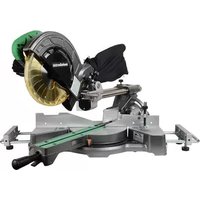
- Blade: For maximum performance, it is recommended that you use the 40-tooth, 10 in. carbide tipped combination blade provided with your saw. The blade is raised and lowered with the height/bevel adjusting handwheel. Bevel angles are locked with the bevel locking lever.
WARNING: Do not use blades rated less than the speed of this tool. Failure to heed this warning
could result in personal injury.
WARNING: Be careful of your hand. Blade are sharp. Wear work gloves when removing or installing
- Blade Guard: Always keep the guard down over the blade for through-sawing cuts.
- Bevel Locking Lever: This lever under the worktable surface on the front of the cabinet, locks the angle setting of the blade.
- Height/Bevel Adjusting Handwheel: Located on the front of the cabinet, this handwheel is used to lower and raise the blade for adjustments or blade replacement. The handwheel also makes the adjustment for bevel angles easy.
- Fence Rails Locking Lever: The lever under worktable surface on the left of the saw releases the fence rails or locks it in place.
- Adjusting Knob: This knob is under the worktable surface on the front of the saw. Turn it clockwise will slide the fence rails to right. Turn it counter-clockwise will slide fence rails to left.
- Outfeed Support: The outfeed support at the back of the tool gives the operator additional support when cutting long workpieces.
- Miter Gauge: The miter gauge aligns the wood for a cross cut. The easy-to-read indicator shows the exact angle for a miter cut, with positive stops at 0°, 22.5° and 45°.
- Miter Gauge Grooves: The miter gauge rides in these grooves on either side of the blade.
- Front Rail: Front rail provides support for the front fence rail and rip fence.
- Rip Fence with a Narrow Fence: A sturdy metal fence guides the workpiece and It can be fixed on three positions of the extension poles with rip fence locking knobs secure in place, the narrow fence can supports workpiece that extends beyond the working table.
- Scale: Located on the front rail, the easy-to-read scale provides precise measurements for rip cuts.
- Riving Knife: A metal piece, slightly thinner than the saw blade, which helps keep the kerf open and prevent kickback.
- Overload Reset Switch: The saw is equipped with the overload reset switch to prevent the saw from overload damage. The saw will stop if the machine was with overloaded cutting or low voltage. Turn the ON/OFF switch to the OFF position and allow the motor to cool down for at least five minutes. And press the overload reset switch button to resume the overload switch. After the motor has cooled down, turn the ON/OFF switch to the ON position; the saw should now start.
- Arbor: The shaft on which a blade or cutting tool is mounted.
- Working table: Surface where the workpiece rests while performing a cutting operation.
- Kerf: The material removed by the blade in a through-cut, or the slot produced by the blade in a non- through or partial cut.
- Push Stick: A push stick should be used for narrow ripping operations when work piece 6 in. (152 mm) wide or less. These aids help to keep the operator’s hands well away from the blade.14 English
- Kickback: A hazard that can occur when the blade binds or stalls, throwing the workpiece back toward the operator.
- Ripping or Rip Cut: A cutting operation along the length of the workpiece.
- Bevel Cut: A cutting operation made with the blade at any angle other than 90° to the table surface.
- Compound Cut: A crosscut made with both a miter angle and a bevel angle.
- Crosscut: A cutting or shaping operation made across the grain or width of the workpiece.
- Miter Cut: A cutting operation made with the workpiece at any angle other than 90° to the blade.
- Non-Through Cut: Any cutting operation where the blade does not extend completely through the thickness of the workpiece.
- Through-sawing: Any cutting operation where the blade extends completely through the thickness of the workpiece.
- Dado Cut: A non-through cut which produces a square-sided notch or trough in the workpiece (requires a special blade).
- Freehand: Performing a cut without the workpiece being guided by a fence, miter gauge, or other aid Never perform any cut freehand with this saw.OVERVIEW Outfeed support Blade guard Wheel Blade wrench Foot Stand leg Power cord Overload reset switch (not shown) Bevel locking lever Bevel scale Adjustable foot Handle I Adjusting knob Rip fence locking knob Narrow fence Stand support assembly Miter gauge Rear fence rail Anti-kickback pawls Rip fence Front rail Switch assembly Height/bevel adjusting handwheel Foot mat Blade guard storage
EnglishTable insert Saw blade Miter gauge groove Locking pin Handle II Push stick Fence rails locking lever Push stick storage Anti-kickback pawls storage Dust extraction port Riving knife Rear fence rail Rip fence locking knob Extension pole Blade wrench storage Miter gauge locking knob Front fence rail Working table Miter gauge storage Power cord storage Power cord storage
English17 English C 10RJ (S)Model 120V~60Hz 15AMotor 4500 RPMNo load speed YesDouble insulated 10" x 5/8" (255mm x 15.9mm) 40T Carbide-tippedBlade 0°~45°Bevel range 28-3/4" x 22" (730mm x 559mm)Working table size 28-3/4" x 2" (730mm x 50mm)Outfeed support size 3-1/8" (79mm)Depth of cut at 0° 2-1/4" (57mm)Depth of cut at 45° 22" (559mm)Max rip to left of blade 35" (889mm)Max rip to right of blade 13/16" (20mm)Max width of dado 96 lbs (44 Kg)Weight SPECIFICATIONSA
Table saw assembly Blade guard assembly (in stored position) Anti-kickback pawls assembly (in stored position) Rip fence assembly (in stored position) 1Outfeed support assembly Miter gauge (in stored position) Push stick (in stored position) Blade wrench (in stored position) 1Stand assembly Stand support assembly Handle I assembly Wheel 1Wheel shaft Flat round head screws M8 x 10 Flat round head screws M8 x 45 Flat round head screws M8 x 100 Locking nut M10 Locking nut M8 Big flat washer 10 5mm Hex key
The following items are included with your table saw:
LOOSE PARTSITEMS NOT SUPPLIED
Flat head screwdriver Screwdriver 13mm wrench / Adjustment wrench Framing square Triangle square ITEMS SUPPLIED Blade wrench (2 pc) 2.5mm Hex key (1 pc) 4mm Hex key (1 pc) 5mm Hex key (1 pc) This product requires assembly.
- Carefully lift saw from the carton and place it on a level work surface.
- Inspect the tool carefully to make sure that no breakage or damage occurred during shipping.
- Do not discard the packing material until you have carefully inspected and satisfactorily operated the tool.
- The saw is factory set for accurate cutting. After assembling it, check for accuracy. If shipping has influenced the settings, refer to specific procedures explained in this Operator’s Manual.
- If any part is missing or damaged, do not attempt to assemble the table saw, plug in the power cord, or turn the switch ON until the missing or damaged part is obtained and is installed correctly.
CAUTION: This tool is heavy. To avoid back injury, lift with your legs, not your back, and get help when needed.
WARNING: Remove the protective polyfoam from between the saw’s housing and the motor.
WARNING: The use of attachments or accessories not listed in this manual might be hazardous and
could cause serious personal injury.
WARNING: Do not attempt to modify this tool or create accessories not recommended for use with
this tool. Any such alteration or modification is misuse, and could result in a hazardous condition leading to possible serious personal injury.
WARNING: To avoid injury, do not connect this table saw to a power source until it is completely
assembled and adjusted and you have read and understood the operator’s manual. CAUTION: Many of the illustrations in this manual show only portions of the table saw. This is intentional so that we can clearly show points being made in the illustrations. Never operate the saw without all guards securely in place and in good operating condition.
WARNING: Do not connect to the power supply until assembly is complete. Failure to comply could
result in accidental starting and possible serious personal injury.
WARNING: Always make sure the table saw is securely mounted to the stand. Failure to heed this
warning can result in serious personal injury.
English ASSEMBLY• Place cardboard or an old blanket on floor in order to protect the surface of the working table.
- Place the table saw assembly (A) upside down on the protective material.
- Attach the stand assembly (B) to the table saw assembly (A) with four flat round head screws M8 x 45 (C) and four locking nut M8 (D)(two holes on the side board of the stand assembly located on the blade wrench storage). (Fig. 2a)
- Attach the tubes of the stand support assembly (E) with the corresponding tubes (located on side of blade wrench storage) on the stand assembly (B) and align the holes. Insert the flat round head screws M8 x 10 (F) into the hole and tighten with 5mm hex key. (Fig. 2b)
- Slide one wheel (G), one big flat washer 10 (H) and one locking nut M10 (I) onto the wheel shaft (J), secure wheel in place by tightening the locking nut M10. Repeat with the second wheel. (Fig. 2c)
- Attach the wheel assembly (K) to the stand assembly (B) with two flat round head screws M8 x 100 (L) and two locking nut M8 (D). (Fig. 2d)
- Attach the tubes of the handle I assembly (M) with the corresponding tubes (located on side of blade guard storage) on the stand assembly (B) and align the holes. Insert the flat round head screws M8 x 10 (F) into the hole and tighten with 5mm hex key. (Fig. 2e) ASSEMBLE THE STAND (Fig. 2a-2e)
- Grasp the handle I (A) and tilt saw back onto wheels until the stand is balanced on the wheels (B) and stand support assembly (C). (Fig. 3a)
- Fold out two lower stand legs (D) (located on side of the wheel). To do this, push the locking pins (E) until they unlock the stand legs (D) from the holes, then swing the stand legs (D) upward until the stand legs (D) are locked with the locking pins (E) engage the holes. (Fig. 3a)
- Grasp the handle I (A) firmly and slowly tilt saw downward until the saw is balanced on the ground. (Fig. 3b-3c)
- Grasp the stand support assembly (F) and lift it up until two other stand legs (G) leaving off the ground, then fold out two stand legs (G). To do this, push the lock pins (H) until they unlock the stand legs (G) from the holes, then swing the stand legs (G) downward until the stand legs are locked with the locking pins (H) engage the holes. (Fig. 3c) Make sure the table saw is balanced with four leg stands stand on the floor.
WARNING: Keep your fingers clear of the hinge points while opening the stand. Danger of fingers
being crushed or contused.
DWith the stand open, resting on a level surface, the stand should not move or rock from side to side. If the stand rocks from side to side, the adjustable foot (A) need adjusting until the stand is balanced.
- Lift the stand slightly so that you may turn the adjustable foot (A) until the stand no longer rocks.
- Turning clockwise will lower the foot.
- Turning counter-clockwise will raise the foot. TO SECURE/LEVEL THE STAND (Fig. 4) Fig. 3a Fig. 3b Fig. 3c Fig. 3d Fig. 4
WARNING: The table saw must be secured. A table saw that
is not properly secured may move or tip over.
A• Lower the blade all the way to down position by turning the height adjusting knob (A) counter-clockwise.
- Lock the blade by turning bevel-lock lever (B) clockwise.
- To remove the table insert: Turn the lock knob (C) counter-clockwise to unlock the table insert (D).Place your index finger in the hole, pulling the table insert (D) out toward the front of the saw.
- To reinstall the table insert: Push the table insert (D) down, turn the lock knob (C) clockwise to lock the table insert in place. When the table insert is not level with the saw table, using a 2.5mm hex key (supplied), adjust the four set screws (E) pre-assembled to the table located on the four holes of the table insert until the table insert is level with the working table.
WARNING: The table insert must be level with the saw table. If the table insert is too high or too low,
the workpiece can catch on the uneven edges, resulting in binding or kickback, which could result in serious personal injury.
WARNING: Be care of your hands avoided to be striked with the saw blade which could result in
- Unplug the saw. To place riving knife in uppermost position (for through cuts)
- Remove the table insert.
- Set the saw blade angle to 0°. CAUTION: This saw is shipped with riving kinfe in “MIDDLE” position. Riving kinfe must be placed in uppermost position to attach anti-kickback pawls and blade guard for all through cut operations.
WARNING: Riving knife has three holes for three positions.
The uppermost position is for all through cuts. The middle position is for non-through cuts (with blade guard and anti-kickback pawls removed). The down position is for dado cuts. (with blade guard and anti-kickback pawls removed). RIVING KNIFE INSTALLATION AND POSITION (Fig.6a-6c) Through cutting riving kinfe installation and position In uppermost position for through cuts
C23 English To place riving knife in middel or down position, refer to the above procedure.
- Raise the saw blade to the uppermost positon by turning the height adjusting knob (A) clockwise.
- Lock the blade by turning bevel-lock lever (B) clockwise.
- Unlock riving knife lock knob (C) by turning it clockwise.
- Grasp the riving knife (D) and pull toward right side of saw to release it from spring-loaded locking pin.
- Position the riving knife in the uppermost position with spring- loaded locking pin is re-engaged.
- Lock the riving knife lock knob (C) by turning it counter-clockwise.
- Reinstall the table insert.
WARNING: Be extremely careful when adjust the riving
knife position. Do not allow hands to contact blade. Fig. 6a Fig. 6b Fig. 6c In middle position for non-through cuts In down position for dado cuts
- Using one opened-ended blade wrench (A), place the flat open end on the flats on the inner blade flange (B).
- Using the other opened-ended blade wrench (C), place the flat open end on the flats on the arbor nut (D). Holding both wrenches firmly, pull the opened-ended blade wrench on the arbor nut (D) forward to the front of the machine.
- Remove arbour nut (D), outer blade flange (E) and saw blade (F). Install the blade:
- Place one new blade on arbour (G). Make sure saw blade teeth point down at the front side of saw table. Place outer flange (E) and nut (D) on arbour and use blade wrenches to tighten nut securely. DO NOT over tighten.
- Lower the saw blade to lowest position and replace table insert.
- Turn height-adjustment knob clockwise to raise blade to maximum height.
- Remove the table insert.
- Remove the blade wrenches from storage area.
WARNING: Be extremely careful when loosening arbour nut.
Keep firm grasp on both wrenches. Do not allow hands to slip and contact blade.
WARNING: The large, flat surface of the outer flange faces
the saw blade and the saw blade (F) is firmly seated aganist the inner flange (B).
WARNING: If the inner flange has been removed, reinstall
it before placing the saw blade on arbor. Failure to do so could cause an accident.
English Fig. 7a Fig. 7b CAUTION: To work properly, the saw blade teeth must point down toward the front of the saw. Failure to heed this instruction could cause damage to the saw blade, the saw or the workpiece.
WARNING: Make sure that the saw blade is installed to rotate in the proper direction. Do not use
grinding wheels, wire brushes, or abrasive wheels on a table saw. Improper saw blade installation or use of accessories not recommended may cause serious injury.
WARNING: Only use a 10 in. diameter blade. To avoid injury from an accidental start, make sure the
switch is in the OFF position and the plug is not connected to the power source outlet. REMOVING AND INSTALLING THE BLADE (Fig. 7a-7b) Anti-kickback pawls should only be installed for through cuts. ANTI-KICKBACK PAWLS AND BLADE GUARD INSTALLATION (Fig. 8a-8b)
WARNING: Make sure the anti-kickback pawls are reinstalled immediately after finishing any non-
through cut operations which require their removal.
WARNING: Replace dull or damaged anti-kickback pawls. Dull or damaged anti-kickback pawls may
not stop a kickback, increasing the risk of serious personal injury.
- Hold the knobs (A) (one on either side of the blade guard) and push the knobs forward to the front of the blade guard and up until the pin comes out from the slot in the mounting bracket (blade guard storage) (B) at bottom front right side of the saw, then remove the blade guard from the U-bracket (blade guard storage) (C) at bottom middle right side of the saw (Fig. 9a).
- Hold and push knobs (A) forward to the front of the the blade guard. Place the pins (D, E) on the blade guard (F) into the slots (G, H) indicated on the riving knife. (Fig. 9b)
- Pull blade guard fully back onto riving knife. Push pin and release it to lock guard into position.
- If blade guard is not parallel to table when riving knife is in uppermost position (through cuts), adjust the set screw (I) as necessary. (Fig. 9c)
- Raise the saw blade to maximum height by turning height adjustment knob clockwise.
- Lock the blade by turning bevel-lock lever clockwise.
- Place the riving knife in the highest position.
- Pull out and hold knob (A) and push anti-kickback pawls up, remove it from the anti-backpawls storage (B) located on inside of the left side of saw. (Fig. 8a)
- Pull out and hold knob (A). Align slot in anti-kickback pawls (C) over the slot (D) indicated of riving kinfe (E). Place the spring pin (F) on the anti-kickback pawls (C) into the slot (D) indicated on the riving knife (E).
- Press anti-kickback pawls (C) down until it snaps into place and release knob (A) to insert the pin (G) into hole (H) indicated on the riving knife (E). BLADE GUARD INSTALLATION (Fig. 9a-9c)
Fig. 8a Fig. 8b Fig. 9a Fig. 9b CAUTION: Pull up on anti-kickback pawl assembly to make sure it is secured to riving knife.
WARNING: Use extra caution when cutting wood products
having slippery surface as the anti-kickback pawls may not always be effective.
WARNING: Gently pull up the anti-kickback pawls to ensure
it is locked into place. Make sure that the anti-kickback pawls move freely and are not stuck in the table insert slot.
WARNING: KEEP GUARDS IN PLACE
and in good working order for all through cut operations. Reinstall the blade guard immediately after finishing any non- through cut operations which require removal of the blade guard. Failure to heed this instruction could result in serious personal injury.
- Loosen two stop screws (A) on the extension poles (B) of the outfeed support (C).
- Loosen the locking knobs (D) under the working table counter- clockwise.
- Insert the rear extension table poles (B) into the two holes in the rear of the work table and into the extension tube brackets that are located under the work table. Position the outfeed support.
- Thread the locking knobs (D) into the the holes under the work table and tighten them.
- Thread the two stop screws (A) into the holes located on ends of the extension poles (B) and tighten them. OUTFEED SUPPORT ASSEMBLY INSTALLATION (Fig. 10a-10b) RIP FENCE INSTALLATION (FIG. 11a-11c)
WARNING: After the installation, check the blade guard to
ensure that it is properly placed and workable before operation the saw.
WARNING: When using the blade guard, lift the left and
right blade guard and make sure that they move independently and contact the table surface. The blade gurad can be raised to adust the cut line, but must be lowered to contact the table surface before starting the saw.
WARNING: Make sure blade guard and anti-kickback pawls
move freely before starting the saw. Ensure the direction of rotation by checking blade teeth point down at the front side of saw table.
- Push down the fence rails lever (A) toward the rear of the saw to unlock it.
- Loosen the rip fence locking knobs (B) on the rip fence.
- Sliding the rip fence (C) to right and swing it up at an angle, then remove the fence from the front and rear fence rails (D). CAUTION: There are three position screws (E, F, G) on the each front and rear fence rails (D) to attach rip fence. Position screws (E, F) use for rip fence on the right of saw blade. Position screws (G) use for rip fence on the left of saw blade. (Fig. 11b) English
The miter gauge (A) can be installed on each miter gauge groove (B) on either side of blade.
- Remove the miter gauge (A) from storage area (C) located on inside of the right side of saw.
- Slide the guide rail (D) of the miter gauge (A) into one of the guide grooves (B) of the saw table intended for this purpose. MITER GAUGE INSTALLATION (FIG. 12a-12b)
- Holding the fence (C) at an angle, align the position screws (front and back) on fence rails with the fence slots (H).
- Slide the slots (H) onto the position screws and rotate the fence down until it rests on the rails.
- Secure the rip fence in place by turning the rip fence locking knobs (B) clockwise.
- Lock the fence rails lever (A). CAUTION: The rip fence should be parallel to the saw blade. If not, refer to the section “ALIGNING RIP FENCE TO BLADE”. CAUTION: Three position screws apply to three different scales: Position screw AA: Begin with 0 to 27 in. end. (Rip fence located on the right of the blade) Position screw BB: Begin with 8 in. to 35 in. end. (Rip fence located on the right of the blade) Position screw CC: Begin with 0 to 22 in. end. (Rip fence located on the left of the blade)
- The table saw has two convenient storage areas (one on either side and back of the saw) specifically designed for the saw’s accessories: rip fence assembly (A), blade guard assembly (B), push stick (C), blade wrenches (D), plug cable (E), anti-kickback pawls (F) and miter gauge (G).
- When not in use, store accessories securely. TO STORE THE TABLE SAW ACCESSORIES (Fig. 13a-13c)
- To fold the stand for moving, return fence rails and outfeed support to inner position. Store the accessories securely.
- Grasp the stand support assembly (A) and lift it up until two stand legs (B) (located on side of the wheel) leaving off the ground, then fold in two stand legs (B). To do this, push the lock pins (C) until they unlock the stand legs (B) from the holes, then swing the stand legs (B) upward until the stand legs are locked with the locking pins (C) engage the holes.
- Grasp the handle I (D) and tilt saw back onto wheels until the stand is balanced on the wheels (E) and stand support assembly (A). (Fig. 14b-14c)
- Fold in other two stand legs (F). To do this, push the locking pins (G) until they unlock the stand legs (F) from holes, then swing the stand legs downward until the stand legs are locked with the locking pins (G) engage the holes.
- Grasp the handle I (D) firmly and tilt saw to you, push the saw to the desired location (Fig. 14e) then either open the stand or store the saw (Fig. 14d & 14f) in a dry environment. FOLDING THE STAND (Fig. 14a-14f)
WARNING: Keep your fingers clear of the hinge points while folding the stand. Danger of fingers
being crushed or contused.
Fig. 14d The dust extraction port (A) with 2 1/2" (6.35 cm) size is located on the back of the table saw. This port can be connected directly to a dust collection system by connecting the pick up end of the dust collection hose to the dust port. CONNECT TO A DUST COLLECTION SYSTEM (Fig. 15)
WARNING: ALWAYS connect to a dust collection system and
the table saw must be regularly checked for dust built up and cleaned frequently, otherwise there is a risk of heat built up and potential fire. Fig. 1530 English OPERATION
- The upper portion of the blade projects up through the table and is surrounded by an insert called the table insert. The height of the blade is set with a height adjusting handle on the height/bevel adjusting handwheel. Detailed instructions are provided in this manual for the basic cut: cross cuts, miter cuts, bevel cuts, and compound cuts. OPERATING COMPONENTS
WARNING: In the event of a power failure or when the tool is not in use, turn the switch OFF. This
action will prevent the tool from accidentally starting when power returns.
WARNING: ALWAYS make sure your workpiece is not in contact with the blade before operating the
switch to start the saw. Blade contact could result in kickback or thrown workpiece.
WARNING: To reduce the risk of accidental starting, ALWAYS make sure the switch is in the OFF
position before plugging saw into the power source.
WARNING: DO NOT use blades rated less than the speed of this tool. Failure to heed this warning
could result in serious personal injury.
WARNING: Never operate the saw with the blade guard removed except
for dado and other non-through cuts. Reinstall the blade guard immediately after finishing any non-through cut operations which require removal of the blade guard. Failure to heed this instruction could result in serious personal injury.
WARNING: The operation of any power tool can result in foreign objects being thrown into the eyes,
which can result in severe eye damage. Always wear safety goggles or standard safety glasses with side shields complying with United States ANSI Z87.1 before commencing power tool operation.
DANGER: Feed the workpiece into the saw blade or cutter only against the direction of rotation.
Feeding the workpiece in the same direction that the saw blade is rotating above the table may result in the workpiece, and your hand, being pulled into the saw blade.
WARNING: To reduce the risk of serious personal injury, have push stick ready to use before starting
WARNING: Before using the saw, verify the following each and every time:
- ALWAYS wear proper eye, hearing and respiratory equipment.
- Blade is securely tightened.
- Bevel angle and fence rails locking lever is locked.
- If ripping, ensure that rip fence locking lever is locked and that the fence is parallel to the blade.
- If crosscutting, miter gauge lock knob is securely tightened.
- The blade guard assembly is properly attached and the anti-kickback assembly is functioning.
WARNING: To reduce the risk of serious personal injury, turn unit off and unplug the tool before
making any adjustments or removing/installing attachments or accessories. An accidental start-up can cause injury. You can use this tool for the purposes listed below:
- Straight-line cutting operations, such as crosscutting, ripping, mitering, and compound cutting.
- Cabinet making and woodworking. NOTE: This table saw is designed to cut wood and wood composition products only. Never cut metals, cement board, or masonry. APPLICATIONS31 English
- The rip fence is used to position workpiece for lengthwise cuts and used for extension table for large workpiece cuts.
- It’s very important to use the blade guard assembly for all through-cut sawing operations. The blade guard assembly includes: riving knife, anti-kickback pawls, and blade guard. Kickback can occur when the blade stalls or binds, causing the workpiece to be kicked back toward the operator with great force and speed. If your hands are near the saw blade, they may be jerked loose from the workpiece and come into contact with the blade. Obviously, kickback can cause serious injury, and it is well worth using precautions to avoid the risks. Kickback can be caused by any action that pinches the blade in the wood, such as the following:
NOTE: Kickback can be avoided by taking following proper precautions:
- Never stand directly in line with the saw blade. Always position your body on the same side of the saw blade as the fence. Kickback may propel the workpiece at high velocity towards anyone standing in front and in line with the saw blade.
- Never reach over or in back of the saw blade to pull or to support the workpiece. Accidental contact with the saw blade may occur or kickback may drag your fingers into the saw blade.
- Never hold and press the workpiece that is being cut off against the rotating saw blade. Pressing the workpiece being cut off against the saw blade will create a binding condition and kickback.
- Align the fence to be parallel with the saw blade. A misaligned fence will pinch the workpiece against the saw blade and create kickback.
- Use a featherboard to guide the workpiece against the table and fence when making non-through cuts such as rabbets, dado cuts. A featherboard helps to control the workpiece in the event of a kickback.
- Use extra caution when making a cut into blind areas of assembled workpieces. The protruding saw blade may cut objects that can cause kickback.
- Support large panels to minimise the risk of saw blade pinching and kickback. Large panels tend to sag under their own weight. Support(s) must be placed under all portions of the panel overhanging the table top.
- Use extra caution when cutting a workpiece that is twisted, knotted, warped or does not have a straight edge to guide it with a miter gauge or along the fence. A warped, knotted, or twisted workpiece is unstable and causes misalignment of the kerf with the saw blade, binding and kickback.
- Never cut more than one workpiece, stacked vertically or horizontally. The saw blade could pick up one or more pieces and cause kickback.
- When restarting the saw with the saw blade in the workpiece, center the saw blade in the kerf so that the saw teeth are not engaged in the material. If the saw blade binds, it may lift up the workpiece and cause kickback when the saw is restarted.
- Keep saw blades clean, sharp, and with sufficient set. Never use warped saw blades or saw blades with cracked or broken teeth. Sharp and properly set saw blades minimise binding, stalling and kickback.
PRECAUTIONS OF KICKBACK
- Making a cut with incorrect blade depth.
- Sawing into knots or nails in the work piece.
- Twisting the wood while making a cut.
- Failing to support the workpiece.
- Cutting warped or wet lumber.
- Using the wrong blade for the type of cut.
- Not following correct operating procedures.
- Failing to use the anti-kickback pawls.
- Cutting with a dull, gummed-up, or improperly set blade.A
WARNING: To reduce the risk of injury, be sure switch is in the OFF position before plugging machine
in. NOTE: A conventional padlock will not fit. To turn saw on and off:
- Flip the switch cover (A) upward.
- Press the switch I (B) to turn on the saw.
- Press the switch paddle (C) to turn off the saw. To lock saw:
- Flip the switch cover (A) downward.
- The holes (D) is provided in the switch for insertion of a padlock with a removable shank to lock the saw off. SWITCH ASSEMBLY (FIG. 16)
WARNING: Make sure the blade guard is in place after adjusting
the blade depth. Failure to heed this instruction could result in serious personal injury. Blade depth should be set so that outer points of blade (A) are higher than workpiece by approximately 1/8 in. to 1/4 in. and bottom of gullets are below top surface of workpiece.
- Turn the bevel locking lever (B) clockwise to tighten it securely.
- Raise blade (A) by turning height adjusting handle (C) on the height/bevel adjusting handwheel (D) clockwise. Lower blade by turning height adjusting handle (C) counter-clockwise.
- Make sure blade (A) is at proper height. CHANGING BLADE DEPTH (FIG. 18) The saw is equipped with an overload switch (A) to prevent the saw from overload damage. The saw will stop if the machine was overloaded with cutting or low voltage. Turn the switch to the OFF position and allow the motor to cool down for at least five minutes. Press the overload switch button to reactivate the overload switch. After the motor has cooled down, turn the switch to the ON position. The saw should now start.
Fig. 20a Fig. 20b FENCE RAILS LOCKING LEVER (Fig. 20a) The fence rails locking lever locks the rip fence in place preventing movement during cutting.
- To lock the fence rails locking lever (A), push it up and toward the front of the saw.
- To unlock the fence rails locking lever (A), push it down and toward the rear of the saw. NARROW FENCE (Fig. 20b-20c)
- When using the narrow fence (B) to support a workpiece that extends beyond the working table, rotate the narrow fence (B) as shown in (fig. 20b) and secure it in the lowest position (b1) for both the front and back slots.
- When using the narrow fence (B) to cut a narrow workpiece, rotate the narrow fence (B) as shown in (fig. 20b) and secure it in the upper position (b2) for both the front and back slots. RIP FENCE (FIG. 20a-20d)
WARNING: To reduce the risk of injury, always make sure the rip fence is parallel to the blade before beginning
any operation. CAUTION: When ripping, always lock the fence rails locking lever. CAUTION: Always use the auxiliary fence (not the narrow fence) when ripping material 1/8 in. (3 mm) or thinner to prevent stock from slipping under the fence. Refer to page 38.
WARNING: Make sure the blade guard is in place after adjusting
blade angle. Failure to heed this instruction could result in serious personal injury. CHANGING BLADE ANGLE (BEVEL) (FIG. 19) CAUTION: A 90° cut has a 0° bevel and a 45° cut has a 45° bevel. CAUTION: If bevel indicator is not at zero when saw blade is at 0°, see the section “ADJUSTING BEVEL INDICATOR”.
- Loosen the bevel locking lever (A) counter-clockwise.
- Adjust bevel angle by first pushing height/bevel adjusting handwheel (B) all the way to the left.
- Holding height/bevel adjusting handwheel, slide bevel indicator to the right to increase angle of blade (C) (bringing it closer to 45° from the tabletop). Holding height/bevel adjusting handwheel, slide bevel indicator to the left to decreases the angle (bringing blade closer to 90° from the tabletop).
- Make sure blade (C) is at desired angle. Tighten bevel locking lever (A) clockwise.Fig. 20c
NOTE: If the narrow fence is not required, always place it in the position as shown (fig. 20c). NOTE: The narrow fence (B) for cutting a narrow workpiece can provide more space for a push stick without removing the blade guard. ADJUSTMENT KNOB (Fig. 20d) The adjustment knob allows smaller adjustments when setting the rip fence.
- Unlock the fence rails locking lever (A).
- Slide the rip fence (C) close to the desired position.
- Slowly turn the adjustment knob (D) to set the rip fence (C) to desired position. Turn the adustment knob (D) clockwise will extend the fence rails (E) to right. Turn the adjustment knob (D) counter-clockwise will extend the fence rails (E) to left.
- Lock the fence rails locking lever (A).35 English
The miter gauge (A) provides accuracy in angled cuts. For very close tolerances, test cut are recommended. There are two miter gauge grooves, one on either side of blade. When making a 90° cross cut, use either miter gauge groove. When making a beveled cross cut (blade tilted in relation to working table, miter gauge should be located in groove on right so that blade is tilted away from miter gauge and hands.
- With miter gauge in miter gauge groove, rotate gauge until desired angle on scale is reached.
- Loosen the locking knobs (B) under the working table counter- clockwise.
- Stand behind saw. Grasp outfeed support (A) with both hands and pull until it is fully extended.
- Tighten the locking knobs (B) clockwise. MITER GAUGE (FIG. 21) The outfeed support (A) slides to give operator additional support for cutting long workpieces. OUTFEED SUPPORT (FIG. 22) Cutting aids such as push stick, push blocks, featherboards and jigs should be used where appropriate to maximize your ability to control your workpiece for a safe and precise cut. When making non-through cuts or ripping narrow stock, always use a push stick, push block, featherboard and/or jig set-up so hands do not come within 6 inches of blade. A push stick is included with your saw. Additional push sticks and other cutting aids can be purchased separately at any authorized dealer. Instructions for making cutting aids can be found at on page 36-38. CUTTING AIDS
WARNING: Use only the push stick provided by the manufacturer or constructed in accordance with
the instructions. This push stick provides sufficient distance of the hand from the saw blade.
WARNING: Never use a damaged or cut push stick. A damaged push stick may break causing your hand to slip
into the saw blade. Push stick can be purchased or made to securely hold down the workpiece against the table when making non-through cuts or ripping narrow stock. The stick must be narrower than the workpiece, with a 90° notch in one end and shaped for a grip on the other end. PUSH STICKS36 English
- In order to operate your table saw safely, you must use a push stick whenever the size or shape of the workpiece would otherwise cause your hands to be within 6 in. (152 mm) of the saw blade or other cutter. A push stick is included with this saw.
- No special wood is needed to make additional push-sticks as long as it’s sturdy and long enough. Make sure that a push stick is long enough and has a notch that fits against the edge of the workpiece to prevent slipping. It’s a good idea to have several push sticks of the same length with different size notches for different workpiece thicknesses.
- The shape can vary to suit your own needs as long as it performs its intended function of keeping your hands away from the blade. Fig. 23b Fig. 23a Included standard push stick Push blocks are blocks used to securely hold down the workpiece against the table. They include some gripping surface or handle to hold the block. Any screws running through the underside of the block to fasten the handle should be recessed in order to avoid contact with the workpiece. PUSH BLOCKS A featherboard is a device used to help control the workpiece by guiding it securely against the table or rip fence. Featherboards are especially useful when ripping small workpieces and for completing non-through cuts. The end is angled with a series of narrow slots to give a friction hold on the workpiece. It is locked in place on the table with a C-clamp. FEATHERBOARDS HOW TO MAKE AN ADDITIONAL PUSH STICK (FIG. 23a-23b)
WARNING: When using featherboard, it must be mounted in front of the blade and used only against the uncut
portion of the workpiece to avoid a kickback that could result in serious injury. Additional Push Stick Construction 20°-30° 90° Notch toprevent handfrom slippingCut here to match wood thicknesswhen neededDrill hole forhanging70° 3/4 in.(19 mm)12 in.(305 mm)2 1/2 in.(63 mm)1/4 in.(6 mm)1/8 in.(3 mm)Sandpaper orold mouse padmaterialWooden dowel4 in.(101 mm)6 in.(152 mm)2 in. (51 mm) Fig. 24a Fig. 24b Fig. 25a Fig. 25b
WARNING: Use a push block when the distance between the fence and the saw blade is less than 2 in. (51 mm).
- Select a piece of wood about 4 in. (101 mm) wide, 6 in. (152 mm) long and 1 (25 mm) to 2 in. (51 mm) thick (a cutoff from a 2 in. (51 mm) by 4 in. (101 mm) makes a good blank for a push block).
- Drill a hole in the block and glue in a dowel to use as a handle (you can angle the hole to provide a more comfortable grip on the handle).
- To finish off the block, glue a piece of sandpaper or some kind of rubber material (old mouse pads work well) to the bottom of the block. HOW TO MAKE A PUSH BLOCK (FIG. 25a-25b)
- Select a solid piece of lumber approximate 3/4 in. (19 mm) thick, 2 1/2 in. (63 mm) wide and 12 in. (305 mm) long.
- Mark the center width on one end of stock. Miter width to 70° (See miter cut section for information on miter cuts).
- Set rip fence to allow approximately a 1/4 in. (6 mm) “finger” to be cut in the stock.
- Feed stock only to mark previously a 1/4 in. (6 mm) “finger” to be cut in the stock.
- Turn saw off and allow blade to completely stop rotating before removing stock.
- Reset rip fence and cut spaced rips into workpiece to allow approximately 1/4 in. (6 mm) fingers and 1/8 in. (3 mm) spaces between fingers. HOW TO MAKE A FEATHERBOARD (FIG. 24a-24b)
WARNING: Always make sure the blade guard and anti-kickback pawls are in place and working properly when
making these cuts to avoid possible injury.
WARNING: Use extra caution when cutting wood products having slippery surface as the anti-kickback pawls
may not always be effective.
WARNING: DO NOT use blades rated less than the speed of this tool. Failure to heed this warning could result
WARNING: To avoid kickback, make sure one side of the workpiece is securely against the rip fence during
any rip cut, and hold the workpiece firmly against the miter gauge during any miter cut.
WARNING: DO NOT attempt compound miter cuts, with blade beveled and miter fence angled, until you are
thoroughly familiar with the basic cuts and understand how to avoid kickback.
WARNING: DO NOT attempt to make any cuts not covered here.
WARNING: Using rip fence as a cutoff gauge when cross cutting will result in kickback which can cause serious
WARNING: NEVER make freehand cuts (cuts without miter gauge or rip fence). Unguided workpieces can result
WARNING: Never make through cuts without the blade guard in place. Failure to
heed this instruction could result in serious personal injury. CAUTION: Make sure hardware does not protrude from front of auxiliary wood fence. Fig. 26
- Select a piece of wood 3/4 in. (19 mm) thick, 2 3/8 in. (60 mm) wide and as long as the rip fence.
- Drill a 1/4 in. (6 mm) hole, 1 in. (25 mm) from each end of the narrow fence.
- Drill a 1/4 in. (6 mm) hole in the middle rip fence 1/2 in. (12.5 mm) from bottom of auxiliary fence.
- Attach auxiliary fence (A) to the narrow fence (B); place wood against narrow fence and firmly on the working table.
- From back side of rip fence, secure wood to fence using wood screws (C) (not included). An auxiliary fence is a device used to close the gap between rip fence and working table. ALWAYS use an auxiliary fence when ripping material 1/8 in. (3 mm) or thinner to prevent stock from slipping under fence. HOW TO MAKE AN AUXILIARY FENCE (FIG. 26)Cross cut Rip cut Miter cut Bevel cross cut Bevel rip cut Compound (bevel) miter cut
- The kerf (the cut made by the blade in the wood) will be wider than the blade to avoid overheating or binding. Make allowance for the kerf when measuring wood.
- Make sure the kerf is made on the waste side of the measuring line.
- Cut the wood with the finish side up.
- Knock out loose knots before making cut.
- Always provide proper support for wood as it comes out of saw. CUTTING TIPS
WARNING: Never use the fence and miter gauge together. This may cause a kickback condition and injury to
- Stand slightly to the side of blade path to reduce the chance of injury should kickback occur.
- Use miter gauge when making cross, miter, bevel and compound miter cuts. To secure angle, lock miter guage in place by twisting lock knob clockwise. ALWAYS tighten lock knob securely in place before use. MAKING CUTS CAUTION: All other cuts are combinations of these basic six. Operating procedures for making each kind of cut are given later in this section. There are six basic cuts: 1) the cross cut, 2) the rip cut, 3) the miter cut, 4) the bevel cross cut, 5) the bevel rip cut, and 6) the compound (bevel) miter cut. TYPES OF CUTS (FIG. 27)
- Set blade to correct depth for workpiece.
- Set miter gauge to 0° and tighten lock knob.
- Make sure wood is clear of blade before turning on saw.
- To turn saw on, press switch button.
- Let blade build up to full speed before moving workpiece into blade.
- Hand closest to blade should be placed on miter gauge lock knob and hand farthest from blade should be placed on workpiece. Feed workpiece into blade.
- When cut is complete, turn saw off. Wait for blade to come to a complete stop before removing workpiece. MAKING A CROSS CUT• Set blade to correct depth for workpiece.
- Unlock the fence rail locking lever and slide rip fence to desired distance from blade for cut.
- Lock the fence rail locking lever.
- Make sure wood is clear of blade before turning on saw.
- When ripping a long workpiece, slide the outfeed support to fully extend.
- To turn saw on, press switch button.
- Position workpiece flat on table with edge flush against rip fence. Let blade build up to full speed before feeding workpiece into blade.
- Once blade has made contact with workpiece, use hand closest to rip fence for guidance. Make sure edge of workpiece remains in solid contact with both rip fence and surface of table. If ripping a narrow piece, use push stick and/or push blocks to move piece through cut and past blade.
- When cut is complete, turn saw off. Wait for blade to come to a complete stop before removing workpiece.
- Set blade to correct depth for workpiece.
- Set miter gauge to the desired angle and tighten lock knob.
- Make sure the wood is clear of the blade before turning on the saw.
- Let the blade build up to full speed before moving the workpiece into the blade.
- Hand closest to blade should be placed on miter gauge lock knob and hand farthest from blade should be placed on workpiece. Feed workpiece into blade.
- When cut is complete, turn saw off. Wait for blade to come to a complete stop before removing workpiece.
- Adjust bevel angle to desired setting.
- Lock bevel locking lever.
- Set blade to correct depth for workpiece.
- Set miter gauge to 0° and tighten lock knob.
- Make sure wood is clear of blade before turning on saw.
- Let blade build up to full speed before moving workpiece into blade.
- Hand closest to blade should be placed on miter gauge lock knob and hand farthest from blade should be placed on workpiece. Feed workpiece into blade.
- When cut is complete, turn saw off. Wait for blade to come to a complete stop before removing workpiece.
MAKING A BEVEL CROSS CUT
WARNING: When ripping, always apply the workpiece feeding force between the fence and the saw blade. Use
a push stick when the distance between the fence and the saw blade is less than 6 in. (152 mm), and use a push block when this distance is less than 2 in. (51 mm). Cutting aids will keep your hand at a safe distance from the saw blade.
WARNING: Make sure that the rip fence is on the right side of the blade to avoid trapping the wood and causing
kickback. Kick-back and serious personal injury will result if the rip fence is placed to the left of the blade. English41 English
- Adjust bevel angle to desired setting.
- Lock bevel locking lever.
- Set blade to correct depth for workpiece.
- Set miter gauge to desired angle and tighten lock knob.
- Make sure wood is clear of blade before turning on saw.
- Let the blade build up to full speed before moving the workpiece into the blade.
- Hand closest to blade should be placed on miter gauge lock knob and hand farthest from blade should be placed on workpiece. Feed workpiece into blade.
- When cut is complete, turn saw off. Wait for blade to come to a complete stop before removing workpiece.
MAKING A COMPOUND (BEVEL) MITER CUT
- Slide the outfeed support to fully extend, and place a support the same height as top of working table behind saw for cut and add supports to sides as needed.
- Depending on shape of panel, use rip fence or miter gauge. If panel is too large to use either rip fence or miter gauge, it is too large for this saw.
- Make sure wood does not touch blade before saw is turned on.
- Position workpiece flat on table with edge flush against rip fence. Let blade build up to full speed before feeding workpiece into blade.
- Use push stick to move piece through cut and past blade.
- When cut is complete, turn saw off. Wait for blade to come to a complete stop before removing workpiece.
MAKING A LARGE PANEL CUT
The use of a non-through cut is essential to cutting grooves and rabbets and dados. Non-through cuts can be made using a standard blade having a diameter of 10 inches, or a dado blade up to 13/16 inches wide with a diameter of 8 inches. Non-through cuts are the only type of cuts that should be made without the blade guard assembly installed. Make sure the blade guard assembly is reinstalled upon completion of this type of cut.
DADOS AND OTHER NON-THROUGH CUTS
- Adjust bevel angle to desired setting.
- Lock bevel locking lever.
- Set blade to correct depth for workpiece.
- Unlock the fence rails locking lever and slide rip fence to desired distance from blade for cut.
- Lock the fence rails locking lever.
- Make sure wood is clear of blade before turning on saw.
- When ripping a long workpiece, slide the outfeed support to fully extend.
- Position workpiece at on table with edge push against rip fence.
- Let blade build up to full speed before moving workpiece into blade.
- Once blade has made contact with workpiece, use hand closest to rip fence for guidance. Make sure edge of workpiece remains in solid contact with both rip fence and surface of table. If ripping a narrow piece, use push stick to move piece through cut and past blade.
- When cut is complete, turn saw off. Wait for blade to come to a complete stop before removing workpiece.B
- Loosen and remove the thumbscrew (A), then open the small baffle (B).
- Clean out the excess dust, and push the small baffle in place, tighten the thumbscrew.
WARNING: Never feed wood with hands when making any non-through cuts such as rabbets. To avoid personal
injury, always use push blocks, push sticks, and/or featherboards.
WARNING: Read the appropriate section which describes the type of cut in addition to this section on non-through
cuts. For example, if your non-through cut is a straight cross cut, read and understand the section on straight cross cuts before proceeding.
WARNING: Once all dado and non-through cuts are completed, unplug saw and reinstall riving knife in
uppermost position. Install anti-kickback pawls and blade guard.
WARNING: Always use push blocks, push sticks, and/or featherboards when making dado cuts to avoid the
risk of serious injury. Dado blades are stacked blades that can be used when making through cut slots in a workpiece, or the non-through cuts described above. Dado blades require a special table insert. Dado blades and table inserts are all sold separately.
This table saw is equipped with a dustshroud and dust collection port. For best results, connect a vacuum to the port at the rear of the saw. After extended use, the saw’s dust collection system may become clogged. To clear the dust collection system: DUST COLLECTION (Fig. 28)
WARNING: To reduce the risk of serious injury when making non-through cuts, follow all applicable warnings
and instructions listed below in addition to those listed above for the relevant through cut.
WARNING: When making a non-through cut, blade is covered by workpiece during most of cut. Be alert to
exposed blade at start and finish of every cut to avoid the risk of personal injury.
MAKING A NON-THROUGH CUT
- Unlock release lever.
- Remove blade guard and anti-kickback pawls. .
- Plug saw into power source and turn saw on.
- Let blade build up to full speed before moving workpiece into blade.
- Always use push blocks, push sticks, and/or featherboard when making non-through cuts to reduce the risk of serious injury.
- When cut is made, turn saw off. Wait for blade to come to a complete stop before removing workpiece.
English Fig. 28WARNING: Before performing any adjustment, make sure tool is unplugged from power supply and switch is in off position. Failure to do so could result in serious personal injury.
WARNING: Make sure the blade guard is reinstalled immediately after making any adjustment which
requires it to be removed. Failure to heed this instruction could result in serious personal injury. ADJUSTMENTS The table saw has been adjusted at the factory for making very accurate cuts. However, some components might have been jarred out of alignment during shipping. Also, over a period of time, readjustment will probably become necessary due to wear. Carefully check alignment with a framing square before beginning adjustments to confirm whether they are necessary. Use test cuts after completing adjustments to avoid damaging workpiece.
EnglishWARNING: Rip fence must be aligned to blade so that wood does not bind, resulting in kickback. Failure to do so could result in serious personal injury.
WARNING: Make sure the blade guard is reinstalled
immediately after making any adjustment which requires it to be removed. Failure to heed this instruction could result in serious personal injury. CAUTION: Unplug saw. Remove blade guard and anti-kickback pawls. Raise the blade by turning height adjusting knob.
WARNING: The adjustment must be correct. If it is not,
kickback could result in a serious injury and inability to make accurate cuts.
- Place the framing square (A) beside the blade (B), and unlock the fence rails locking lever (C) to move the rip fence (D) up to the square.
- Lock the fence rails locking lever (C) and note the measurement on the rip scale.
- Move the fence back and rotate the framing square (A) 180° to check the other side.
- If the two measurements are not the same, loosen the position screws (E) on the extension poles and then align it.
- Retighten the position screws with 4 mm hex key (supplied). Recheck alignment after position screws are retightened.
- Reinstall the blade guard and anti-kickback pawls.
- Make two or three test cuts using scrap wood. If the cuts are not true, repeat the process. DO NOT loosen any position screws for this adjustment until alignment has been checked with a square to be sure adjustment are necessary. Once screws are loosened, items must be reset.
English Rip fence and blade alignment is set at factory and in most cases will not need to be adjusted. However, the alignment should always be checked after installing blade or before making cuts, and can be adjusted if necessary. If rip fence is out of alignment with blade, adjustment is needed. ALIGNING RIP FENCE TO BLADE (FIG. 29a-29b) Fig. 29a Fig. 29b
CAUTION: For easy of use, bevel adjust should stop at 45° and 90°.
WARNING: Make sure the blade guard and anti-kickback
pawls are reinstalled immediately after making any adjustment which requires it to be removed. Failure to heed this instruction could result in serious personal injury. TO CHECK 90° (0°) BEVEL (Fig. 30a-30b):
- Raise the blade to the maximum height by turning the height adjusting knob clockwise.
- Remove the anti-kickback pawls and blade guard.
- Using a framing square (A), set the blade (B) to exactly 90°.
- If the blade stops bevelling before it gets to 90°, loosen the 90° stop set screw (C) (located at the left of the bevel track on the front), and then adjust it to 90°.
- With the blade set at 90°, slowly turn the 90° stop set screw (C) until you feel resistance. Bevel the blade away from 90° a little, and then back to the stop.
- Re-measure the angle and repeat the stop adjustment as necessary until the blade stops at 90°. TO CHECK 45° BEVEL (Fig. 30c-30d):
- Raise the blade to the maximum height by turning the height adjusting knob clockwise.
- Remove the anti-kickback pawls and blade guard.
- Using a triangle square (D), set the blade (B) to exactly 45°.
- If the blade stops bevelling before it gets to 45°, loosen the 45° stop set screw (E) (located at the right of the bevel track on the front), and then adjust it to 45°.
- With the blade set at 45°, slowly turn the 45° stop set screw (E) until you feel resistance. Bevel the blade away from 45° a little, and then back to the stop.
- Re-measure the angle and repeat the stop adjustment as necessary until the blade stops at 45°. This saw has positive stops that will quickly position the saw blade at 90° (0°) or 45° to the table. Angle settings of saw have been set at the factory and, unless damaged in shipping, should not require setting during assembly. After extensive use, they may need to be checked. BEVEL ADJUSTMENT (FIG. 30a-30d)
- Unlock the fence rails lock lever (A).
- Set the blade at 0° bevel and move the fence (B) in until it touches the blade.
- Lock the fence rails lock lever (A).
- Loosen the rip fence scale indicator screws (C, D) and set the red line (E) on the rip fence scale indicator (F) to read zero.
- Retighten the rip fence indicator screws (C, D). The top rip scale reads correctly only when the fence is mounted on the right side of the blade and is in position 1 (G) (for 0 to 27 in. ripping) [not the 35 in. position]. The bottom scale reads correctly only when the fence is mounted on the right side of the blade and in position 2 (H) (for 8 in. to 35 in. ripping). ADJUSTING RIP FENCE SCALE INDICATOR (FIG. 31)
- With blade perpendicular to table, loosen screw (A).
- Set the bevel indicator (B) to align with 0° on bevel scale (C).
- Retighten screw (A). Adjust the red line on the bevel indicator if it is not aligned with zero when the blade is perpendicular to the table. ADJUSTING BEVEL INDICATOR (FIG. 32) Fig. 31 Fig. 32
GWARNING: When servicing, use only identical replacement parts. Use of any other part may create a hazard or cause product damage.
WARNING: Always wear safety goggles or safety glasses with side shields during power tool operation or when
blowing dust. If operation is dusty, also wear a dust mask.
WARNING: Before performing any maintenance, make sure the tool is unplugged from the power supply and
switch is in the off position.
WARNING: DO NOT at any time let brake fluids, gasoline, petroleum-based products, penetrating oils, etc.,
come in contact with plastics parts. Chemicals can damage, weaken, or destroy plastic.
WARNING: Make sure the blade guard is reinstalled immediately after finishing any maintenance which requires
it to be removed. Failure to heed this instruction could result in serious personal injury. NOTE: Specifications are subject to change without any obligation on the part of metabo HPT. MAINTENANCE
- Avoid using solvents when cleaning plastic parts. Most plastics are susceptible to damage from various types of commercial solvents and may be damaged by their use. Use clean cloths to remove dirt, dust, oil, grease, etc.
- Periodically check all clamps, nuts, bolts, and screws for tightness and condition. Make sure the table insert is in good condition and level with the working table.
- Check the blade guard assembly after performing maintenance to make sure it is installed correctly and functioning properly.
- Clean plastic part only with a soft damp cloth. DO NOT use any aerosol or petroleum solvents. GENERAL MAINTENANCE All of the bearings in this tool are lubricated with a sufficient amout of high grade lubricant for the life of the unit under normal operating conditions. Therefore, no further lubrication is required. LUBRICATION All quality power tools will eventually require servicing or replacement of parts because of wear from normal use. To assure that only authorized replacement parts will be used and that the double insulation system will be protected, all service (other than routine maintenance) must be performed by an AUTHORIZED metabo HPT REPAIR CENTER ONLY.
After operation of the tool has been completed, check that the following has been performed:
- Switch is in OFF position.
- Power plug has been removed from the receptacle. When the tool is not use, keep it stored in a dry place out of the reach of children. STORAGE
EnglishCORRECTIVE ACTIONPROBLEM CAUSEPROBLEM
- Allow motor to cool and reset by pushing overload reset switch.
- Have the cord replaced by an Authorized Service Center.
- Saw is not plugged in.
- Fuse blown or circuit breaker tripped.
- Cord is damaged. Saw will not start.
- See section “Aligning rip fence to blade”.
- Positive stop not adjusted correctly.
- Bevel angle pointer not set accurately.
- Rip fence not properly aligned. Does not make 45° and 90° rip cuts.
- See section “Aligning rip fence to blade”.
- Select another piece of wood.
- Rip fence not aligned with blade.
- Warped wood, edge against fence is not straight. Material pinches blade when ripping.
- See section “Riving knife and saw blade alignment”.
- Riving knife not aligned correctly with blade. Material binds on riving knife.
- Replace with the specified blade.
- Turn the blade around.
- Remove the blade and clean with turpentine and coarse steel wool.
- Clean table with turpentine and steel wool.
- Blade mounted backwards.
- Gum or pitch on blade.
- Incorrect blade for work being done.
- Gum or pitch on blade causing erratic feed. Saw makes unsatisfactory cuts.
- See section “Riving knife and saw blade alignment”.
- Install and use rip fence.
- Install and use riving knife (with guard).
- Replace with the specified blade.
- Push material all the way past saw blade before releasing work.
- Riving knife not aligned correctly with blade.
- Feeding stock without rip fence.
- Riving knife not in place.
- The operator letting go of material before it is past saw blade.
- Miter angle lock knob is not tightened. Material kicked back from blade.
- Brush or blow out loose dust and dirt.
- Sawdust and dirt in elevation/ beveling mechanisms. Blade does not raise or bevel freely.
- Replace with adequate size cord.
- Contact your electric company.
- Extension cord too light or too long.
- Low house voltage. Blade does not come up to speed or reset trips too easily.
- Tighten all mounting hardware.
- Reposition on flat, level surface.
- Securely the workbench to floor.
- The saw is not mounted securely to the stand.
- Stand is on uneven floor.
- Workbench is moving.
- Damaged saw blade. Machine vibrates excessively.
WARNING: To avoid injury from an accidental start, turn the switch OFF and always remove the plug from the
power source before making any adjustments. All electrical or mechanical repairs should be done only by qualified service technicians. Contact metabo HPT Authorized Service Center. Consult metabo HPT Authorized Service Center if for any reason the motor will not run. TROUBLESHOOTING
GUARD (EXCEPT NON-THROUGH
CUT). Using this tool without blade guard may result in serious injury.
- Make surethe blade guard is reinstalled immediately after finishing any non-through cut operations which require removal of the blade guard. Failure to heed this instruction could result in serious personal injury. WARNING
- Asegúrese surethe protector de la hoja se vuelve a instal ar inmediatamente después de terminar cualquiera que no sea a través cortar las operaciones que requieren la eliminación de la protección de la hoja. El incumplimiento de esta instrucción podría resultar en lesiones personales graves.ADVERTENCIA
- NEVER OPERATE THIS TOOL WITHOUT BLADE GUARD (EXCEPT NON-THROUGH CUT). Using this tool without blade guard may result in serious injury.
- Make surethe blade guard is reinstalled immediately after finishing any non-through cut operations whic h require removal of the blade guard. Failure to heed this instruction could result in serious personal injury.WARNING
- NE JAMAIS UTILISER CET OUTIL SANS LAME (SAUF NON PAR COUPE). Grâce à cet outil, sans pro tège-lame peut entraîner des blessures graves.
tool and wait for saw blade to stop before moving workpiece or changing se ttings. WARNING
No. Description Qty Bolt Left blade guard Latch cap Split washer Ø4 Flat Washer 6 Blade guard supporting seat Stop pin Blade guard supporting seat Spring Sliding detent Right blade guard Washer on shaft 11 Anti-kickback pawl (B) Latch Ø9 Anti-kickback pawl spring Ø0.8 Anti-kickback pawl spring Supporting seat Washer Anti-kickback pawl (A) Cylindrical pin 4×20 Knob Fixing holder Hexagon socket set screw with flat point M5×10 Table insert Table insert locking plate Flat Washer Ø4 Spring washer 4 Cross pan head screw M4×10 Hexagon socket screw M14 Extension table Extension rod Stop collar Cross pan head screw M6×12 Cross pan head screw M4×8 Sliding rail (A) Hexagon socket cap screws M5×16 Rail Friction pad Worktable Positioning screw (B) Big flat washer Ø6 Hex nut M6 Adjusting bolt Adjusting wheel Lock nut M4 Table insert locking block (A) Table insert locking block (B) Pointer Cover Lever (right)
Cross recess head screw Limited position screw Rip fence holder base (right) Vice rip fence fixing plate (A) Positioning spring Hex nut M5 Cross pan head screw M5 Fixing plate Locking spring Locating pin Vice rip fence fixing plate (B) Vice rip fence fixing plate (C) Rip fence Vice rip fence Positioning screw (A) Power cords Cross pan head screw M5×10 Rip fence holder base (left) Moving baffle fixed seat Lever (left) Bolt (A) Handle for miter gauge Miter gauge Steel ball Compressing spring (B) Pointer Hexagon socket set screw with flat point M6×12 Bar for miter gauge Location-limted plate (A) Locking block Locking lever Longer nut M8 (B) Hex nut M8 Cylindrical pin 3×16 Front locking rod Compression spring Location-limted plate (B) Flat Washer Ø5 Spring washer Ø5 Cross pan head screw M5×12 Rear locking rod (B) Spring Cylindrical pin 3×12 Slider (A) Rear locking rod (A) Clamp Knob cover Hex nut M10 Flat Washer Ø10
No. Description Qty Rotation knob Adjusting gear Adjusting support seat (C) Adjusting spring Cross pan head screw M5×16 Adjusting support seat (B) Adjusting support seat (A) Big flat washer Ø10 Split washer Ø8 Cylindrical pin 4×16 Adjusting rod Moving baffle Sheath for locking lever Cross pan head screw M5×10 Small baffle Trunnion protection guard Arbor nut Blade outer flange Blade Blade inner flange Trunnion fixed seat Spring washer Ø6 Hexagon socket cap screws M6×20 Trunnion slider Trunnion Up and down adjusting rod (B) Key Adjusting seat Bevel gear Washer on shaft 10 Cover plate Blade protection plate Motor component Special bolt Eccentric hand Cam pressing plate Clamping bush Hex nut M6 Steel ball Ø8 Spring Ø0.7 Hexagon socket set screw with flat point M10×8 Guide pillar Cross pan head screw M5×20 Hexagon bolt M8×30 Hex nut M4 Antiflex bushing Wire clip Cross pan head screw M4×12 Cord warp
Cross pan head screw M5×40 Overload protection Cross recessed pan head tapping screw ST3.9×9.5 Switch cover Label for overload protection Nut for overload protection Hexagon socket set screw with flat point M5×10 Hexagon socket set screw with flat point M5×20 Hexagon socket set screw with flat point M5×6 Eccentric limit block Back plate Angle adjusting base Cross recessed countersunk head screw M4×12 Cross recessed pan head tapping screw ST4.2×9.5 Front panel Footing (B) Push sticker Bevel label Rotation pin Switch panel Switch Switch flap Cross recessed pan head tapping screw ST4.2×16 Footing (A) Miter gauge storage Frame assembly Blade guard storage (B) Blade guard storage (A) Push sticker storage (B) Push sticker storage (A) Hexagon socket head cap screws M6×14
No. Description Qty No. Description Qty
Footing Hexagon socket head cap screws M6×40
Shaft retaining ring Up and down adjusting rod (A) set
Some dust created by power sanding, sawing, grinding, drilling, and other construction activities contains chemicals known to the State of California to cause cancer, birth defects or other reproductive harm. Some examples of these chemicals are:
- Lead from lead-based paints,
- Crystalline silica from bricks and cement and other masonry products, and
- Arsenic and chromium from chemically-treated lumber. Your risk from these exposures varies, depending on how often you do this type of work. To reduce your exposure to these chemicals: work in a well ventilated area, and work with approved safety equipment, such as those dust masks that are specially designed to filter out microscopic particles.