SV12SG - Sander HITACHI - Free user manual and instructions
Find the device manual for free SV12SG HITACHI in PDF.
User questions about SV12SG HITACHI
0 question about this device. Answer the ones you know or ask your own.
Ask a new question about this device
Download the instructions for your Sander in PDF format for free! Find your manual SV12SG - HITACHI and take your electronic device back in hand. On this page are published all the documents necessary for the use of your device. SV12SG by HITACHI.
USER MANUAL SV12SG HITACHI
natural_image
Line drawing of a manual power tool with meshing and mounting base (no text or symbols)SAFETY INSTRUCTIONS AND INSTRUCTION MANUAL
WARNING
IMPROPER OR UNSAFE use of this power tool can result in death or serious bodily injury!
This manual contains important information about product safety. Please read and understand this manual BEFORE operating the power tool. Please keep this manual available for other users and owners before they use the power tool. This manual should be stored in safe place.
INSTRUCTIONS DE SECURITE ET MODE D'EMPLOI
AVERTISSEMENT
IMPORTANT SAFETY INFORMATION .... 3
MEANINGS OF SIGNAL WORDS 3
SAFETY 4
GENERAL SAFETY RULES 4
SPECIFIC SAFETY RULES AND SYMBOLS ...... 6
IMPORTANT SAFETY INFORMATION
Read and understand all of the safety precautions, warnings and operating instructions in the Instruction Manual before operating or maintaining this power tool.
Most accidents that result from power tool operation and maintenance are caused by the failure to observe basic safety rules or precautions. An accident can often be avoided by recognizing a potentially hazardous situation before it occurs, and by observing appropriate safety procedures.
Basic safety precautions are outlined in the "SAFETY" section of this Instruction Manual and in the sections which contain the operation and maintenance instructions.
Hazards that must be avoided to prevent bodily injury or machine damage are identified by WARNINGS on the power tool and in this Instruction Manual.
NEVER use this power tool in a manner that has not been specifically recommended by HITACHI.
MEANINGS OF SIGNAL WORDS
WARNING indicates a potentially hazardous situations which, if ignored, could result in death or serious injury.
CAUTION indicates a potentially hazardous situations which, if not avoided, may result in minor or moderate injury, or may cause machine damage.
NOTE emphasizes essential information.
SAFETY
GENERAL SAFETY RULES
⚠ WARNING: Read and understand all instructions.
Failure to follow all instructions listed below, may result in electric shock, fire and/or serious personal injury.
SAVE THESE INSTRUCTIONS
1. Work Area
(1) Keep your work area clean and well lit. Cluttered benches and dark areas invite accidents.
(2) Do not operate power tools in explosive atmospheres, such as in the presence of flammable liquids, gases, or dust. Power tools create sparks which may ignite the dust of fumes.
(3) Keep bystanders children, and visitors away while operating a power tool. Distractions can cause you to lose control.
2. Electrical Safety
(1) Double Insulated tools are equipped with a polarized plug (one blade is wider than the other). This plug will fit in a polarized outlet only one way. If the plug does not fit fully in the outlet, reverse the plug. If it still does not fit, contact a qualified electrician to install a polarized outlet. Do not change the plug in any way. Double Insulation ☐ eliminates the need for the three wire grounded power cord and grounded power supply system.
(2) Avoid body contact with grounded surfaces such as pipes, radiators, ranges and refrigerators. There is an increased risk of electric shock if your body is grounded.
(3) Do not expose power tools to rain or wet conditions. Water entering a power tool will increase the risk of electric shock.
(4) Do not abuse the cord. Never use the cord to carry the tools or pull the plug from a receptacle. Keep cord away from heat, oil, sharp edges or moving parts. Replace damaged cords immediately. Damaged cords increase the risk of electric shock.
(5) When operating a power tool outside, use an outdoor extension cord marked "W-A" or "W". These cords are rated for outdoor use and reduce the risk of electric shock.
3. Personal Safety
(1) Stay alert, watch what you are doing and use common sense when operating a power tool. Do not use tool while tires or under the influence of drugs, alcohol, or medication. A moment of inattention while operating power tools may result in serious personal injury.
(2) Dress properly. Do not wear loose clothing or jewelry. Contain long hair. Keep your hair, clothing and gloves away from moving parts. Loose clothes, jewelry, or long hair can be caught in moving parts.
(3) Avoid accidental starting. Be sure switch is off before plugging in. Carrying tools with your finger on the switch or plugging in tools that have the switch on invites accidents.
(4) Remove adjusting keys or wrenches before turning the tool on. A wrench or a key that is left attached to a rotating part of the tool may result in personal injury.
(5) Do not overreach. Keep proper footing and balance at all times. Proper footing and balance enables better control of the tool in unexpected situations.
(6) Use safety equipment. Always wear eye protection. Dust mask, non-skid safety shoes, hard hat, or hearing protection must be used for appropriate conditions.
4. Tool Use and Care
(1) Use clamps or other practical way to secure and support the workpiece to a stable platform. Holding the work by hand or against your body is unstable and may lead to loss of control.
(2) Do not force tool. Use the correct tool for your application. The correct tool will do the job better and safer at the rate for which it is designed.
(3) Do not use tool if switch does not turn it on or off. Any tool that cannot be controlled with the switch is dangerous and must be repaired.
(4) Disconnect the plug form the power source before making any adjustments, changing accessories, or storing the tool. Such preventive safety measures reduce the risk of starting the tool accidentally.
(5) Store idle tools out of reach of children and other untrained persons. Tools are dangerous in the hands of untrained users.
(6) Maintain tools with care. Keep cutting tools sharp and clean. Properly maintained tools, with sharp cutting edges are less likely to bind and are easier to control.
(7) Check for misalignment or binding of moving parts, breakage of parts, and any other condition that may affect the tool's operation. If damaged, have the tool serviced before using. Many accidents are caused by poorly maintained tools.
(8) Use only accessories that are recommended by the manufacturer for your model. Accessories that may be suitable for one tool, may become hazardous when used with another tool.
5. Service
(1) Tool service must be performed only by qualified repair personnel. Service or maintenance performed by unqualified personnel could result in a risk of injury.
(2) When servicing a tool, use only identical replacement parts. Follow instructions in the Maintenance section of this manual. Use of unauthorized parts or failure to follow Maintenance Instruction may create a risk of electric shock or injury.
SPECIFIC SAFETY RULES AND SYMBOLS
- Hold tools by insulated gripping surfaces when performing an operation where the cutting tool may contact hidden wiring or its own cord. Contact with a "live" wire will make exposed metal parts of the tool "live" and shock the operator.
- ALWAYS wear ear protectors when using the tool for extended periods.

natural_image
Abstract black-and-white icon of a human head silhouette with a thermometer inside, no text or symbols present.Prolonged exposure to high intensity noise can cause hearing loss.
- NEVER touch moving parts.
NEVER place your hands, fingers or other body parts near the tool's moving parts.
- NEVER operate without all guards in place.
NEVER operate this tool without all guards or safety features in place and in proper working order. If maintenance or servicing requires the removal of a guard or safety feature, be sure to replace the guard or safety feature before resuming operation of the tool.
- Use right tool.
Don't force small tool or attachment to do the job of a heavy-duty tool.
Don't use tool for purpose not intended —for example— don't use circular saw for cutting tree limbs or logs.
- NEVER use a power tool for applications other than those specified.
NEVER use a power tool for applications other than those specified in the Instruction Manual.
- Handle tool correctly.
Operate the tool according to the instructions provided herein. Do not drop or throw the tool. NEVER allow the tool to be operated by children, individuals unfamiliar with its operation or unauthorized personnel.
- Keep all screws, bolts and covers tightly in place.
Keep all screws, bolts, and plates tightly mounted. Check their condition periodically.
- Do not use power tools if the plastic housing or handle is cracked.
Cracks in the tool's housing or handle can lead to electric shock. Such tools should not be used until repaired.
- Blades and accessories must be securely mounted to the tool.
Prevent potential injuries to yourself or others. Blades, cutting implements and accessories which have been mounted to the tool should be secure and tight.
- Keep motor air vent clean.
The tool's motor air vent must be kept clean so that air can freely flow at all times.
Check for dust build-up frequently.
- Operate power tools at the rated voltage.
Operate the power tool at voltages specified on its nameplate.
If using the power tool at a higher voltage than the rated voltage, it will result in abnormally fast motor revolution and may damage the unit and the motor may burn out.
- NEVER use a tool which is defective or operating abnormally.
If the tool appears to be operating unusually, making strange noises, or otherwise appears defective, stop using it immediately and arrange for repairs by a Hitachi authorized service center.
- NEVER leave tool running unattended. Turn power off.
Don't leave tool until it comes to a complete stop.
- Carefully handle power tools.
Should a power tool be dropped or struck against hard materials inadvertently, it may be deformed, cracked, or damaged.
- Do not wipe plastic parts with solvent.
Solvents such as gasoline, thinner benzine, carbon tetrachloride, and alcohol may damage and crack plastic parts. Do not wipe them with such solvents.
Wipe plastic parts with a soft cloth lightly dampened with soapy water and dry thoroughly.
- ALWAYS wear eye protection that meets the requirement of the latest revision of ANSI
natural_image
Silhouette of a helmet with a visor and arrow pointing to it (no text or symbols)Standard Z87.1.
- NEVER leave the orbital sander on floor and so on while spinning.
- NEVER apply water or lubricating oil, otherwise hazards from electrical shocks may result.
- NEVER push the orbital sander too strongly onto a surface.
Pushing the orbital sander too strongly may cause the sanding paper to tear or shorten the life of the sander itself.
- ALWAYS operate the orbital sander safely for correct use.
This orbital sander is a portable dry plane surface sander that was designed for finishing wood and metal surfaces and ground coats.
- ALWAYS securely installing the sanding paper.
- ALWAYS wear a protective mask when operating the orbital sander in confined spaces.
- Definitions for symbols used on this tool
V ...... volts
Hz ...... hertz
A ...... amperes
n_0 ...... no load speed
W ...... watt
回...... Class II Construction
---/min ... revolutions per minute
To ensure safer operation of this power tool, HITACHI has adopted a double insulation design. "Double insulation" means that two physically separated insulation systems have been used to insulate the electrically conductive materials connected to the power supply from the outer frame handled by the operator. Therefore, either the symbol "☐" or the words "Double insulation" appear on the power tool or on the nameplate.
Although this system has no external grounding, you must still follow the normal electrical safety precautions given in this Instruction Manual, including not using the power tool in wet environments.
To keep the double insulation system effective, follow these precautions:
○Only HITACHI AUTHORIZED SERVICE CENTER should disassemble or assemble this power tool, and only genuine HITACHI replacement parts should be installed.
○Clean the exterior of the power tool only with a soft cloth moistened with soapy water, and dry thoroughly.
Never use solvents, gasoline or thinners on plastic components; otherwise the plastic may dissolve.
SAVE THESE INSTRUCTIONS AND
MAKE THEM AVAILABLE TO OTHER USERS
AND
OWNERS OF THIS TOOL!
FUNCTIONAL DESCRIPTION
NOTE:
The information contained in this Instruction Manual is designed to assist you in the safe operation and maintenance of the power tool.
NEVER operate, or attempt any maintenance on the tool unless you have first read and understood all safety instructions contained in this manual.
Some illustrations in this Instruction Manual may show details or attachments that differ from those on your own power tool.
NAME OF PARTS

text_image
Switch Nameplate Housing (B) Pad Paper Clip Base Dust Bug Housing (A)Fig. 1
SPECIFICATIONS
| Motor Single Phase, Series Commutator Motor | |
| Power source Single Phase 120V AC 60 Hz | |
| Current 1.7 A | |
| No-load speed 14000/min | |
| Sanding pad size 4-3/8" | × 4'' (110 mm × 100 mm) |
| Sanding paper size 4-1/2" | × 5-1/2'' (114 mm × 140 mm) |
| Weight 2.42 lbs (1.1 kg) | |
ASSEMBLY AND OPERATION
APPLICATIONS
○Finish polishing of woodwork surfaces.
○Sanding surfaces of woodwork or sheet metal prior to painting, etc.
PRIOR TO OPERATION
1. Power source
Ensure that the power source to be utilized conforms to the power source requirements specified on the product nameplate.
2. Power switch
Ensure that the switch is in the OFF position. If the plug is connected to a receptacle while the switch is in the ON position, the power tool will start operating immediately and can cause serious injury.
3. Extension cord
When the work area is far away from the power source, use an extension cord of sufficient thickness and rated capacity. The extension cord should be kept as short as practicable.

natural_image
Black and white illustration of a hand with a lightning bolt symbol (no text or numbers)WARNING:
Damaged cord must be replaced or repaired.
4. Check the receptacle
If the receptacle only loosely accepts the plug, the receptacle must be repaired. Contact a licensed electrician to make appropriate repairs.
If such a fautly receptacle is used, it may cause overheating, resulting in a serious hazard.
5. Check your working environment
Ensure the following before operation;
○No flammable gas, liquid, or object at worksite.
○Sanding thin steel sheet may cause a high booming sound. In this case, place a rubber mat under the workpiece.
○Take appropriate noise preventive measures to prevent adverse affects on the environment by electrical noise.
○Clear the area of children or unauthorized personnel.
6. Installing the sanding paper
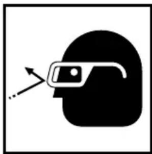
(1) Peel off the paper on the backside of the quick stick sanding paper.
Since adhesive agent is applied on the paper on the backside of the quick stick sanding paper, make sure that it is not exposed to dust or other particles. Fig. 2.
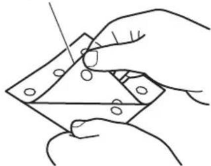
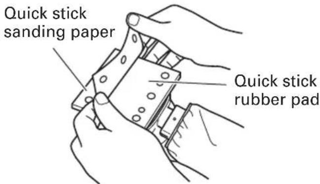
(2) To attach the quick stick sanding paper, match its holes to the holes in the quick stick rubber pad.
NOTE:
Wipe off any dust or oil on the pad before attaching the sanding paper to it.
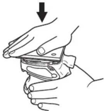
(3) Surely attach the quick stick sanding paper by strongly and evenly pressing with your palm. (Fig. 4)
NOTE:
If you reattach the quick stick sanding paper several times, its adhesive strength will become lowered. Please try to attach it only once.
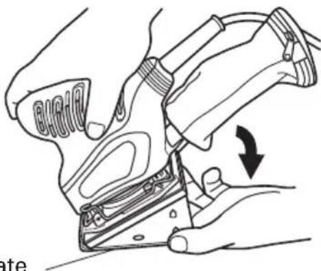
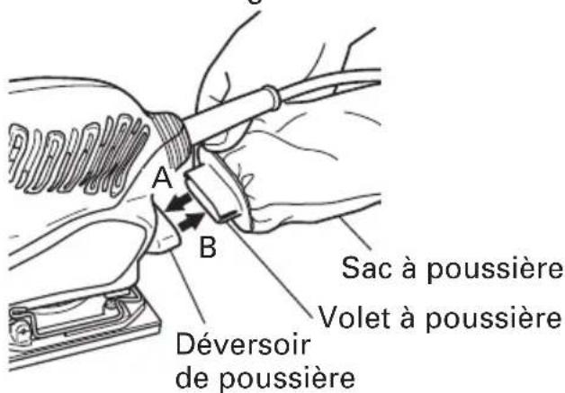
7. Attaching and removing the dust bag
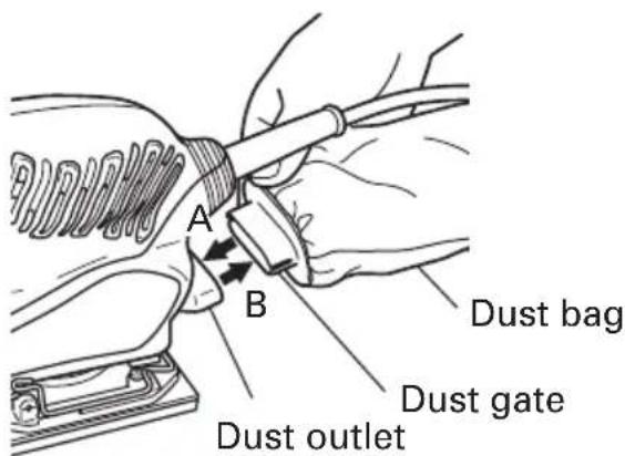
(1) Attaching the dust bag
As shown in Fig. 5, hold the dust gate and push it in the direction of arrow A to attach it to the dust outlet.
(2) Removing the dust bag
As shown in Fig. 5, hold the dust gate and pull it in the direction of arrow B to remove it from the dust outlet.
Paper on backside
natural_image
Line drawing of two hands holding a folded paper or sheet with circular holes (no text or symbols)Fig. 2
text_image
Quick stick sanding paper Quick stick rubber padFig. 3
Press strongly
natural_image
Line drawing of hands holding a small electronic device with a downward arrow indicating compression (no text or symbols)Fig. 4
text_image
A B Dust bag Dust gate Dust outletFig. 5
WARNING: Never apply water or grinding fluid when sanding. This could result in electrical shock.
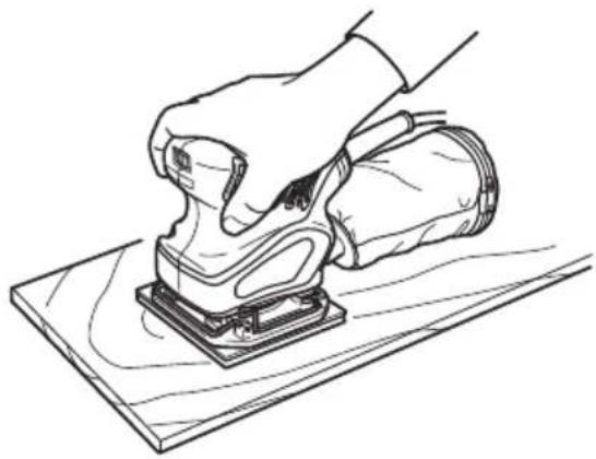
- How to hold the orbital sander
While gripping the housing, lightly press the sander against the surface to be sanded so that the sanding paper uniformly contacts the surface, as shown in Fig. 6. DO NOT apply excessive pressure to the sander while sanding. Excessive pressure may cause overload of the motor, reduced service life of the sanding paper, and lowered sanding or polishing efficiency.
- How to move the orbital sander
For optimum operating efficiency, alternately move the sander forward and backward at a constant speed and balance.
- Switching the sander ON and OFF
The power can be turned on by setting the lever to ON (1) and turned off by setting the lever to OFF (0).
natural_image
Line drawing of a hand using a power tool on a wooden surface (no text or symbols)Fig. 6
NOTE:
Never turn the power switch ON when the sander is contacting the surface to be sanded. This is necessary to preclude damage to the material. The same applies when switching the power OFF.

CAUTION:
- Immediately after use, always turn the sander off and unplug it.
●Since the sander may suck in dust and debris, be careful not to place it where there is much dust and debris when it is still spinning right after use.
HOW TO INSTALL THE OPTIONAL ACCESSORIES
⚠ WARNING: Be sure to switch power OFF and disconnect the plug to avoid accidents.
- Installing the sponge pad (velcro type), the felt pad and the round rubber pad.
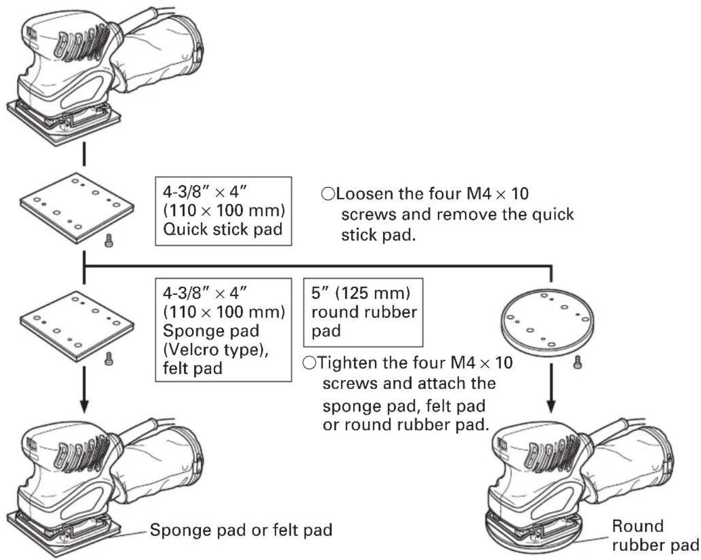
flowchart
graph TD
    A["Initial Screen"] --> B["4-3/8" × 4" (110 × 100 mm) Quick stick pad"]
    B --> C["4-3/8" × 4" (110 × 100 mm) Sponge pad (Velcro type), felt pad"]
    C --> D["Sponge pad or felt pad"]
    D --> E["Round rubber pad"]
    F["Loosen four M4 × 10 screws and remove the quick stick pad."] --> G["5" (125 mm) round rubber pad"]
    G --> H["Tighten the four M4 × 10 screws and attach the sponge pad, felt pad or round rubber pad."]
Fig. 7
CAUTION: Replace only the pad and use the other parts just as they are. The sander will vibrate greatly if parts other than the pad are removed or exchanged.
2. Installing the sanding paper
[4-1/2" × 5-1/2" (114 × 140 mm) sanding paper (Clip type)]
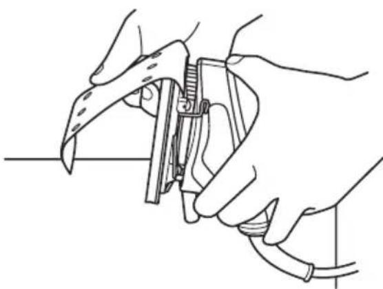
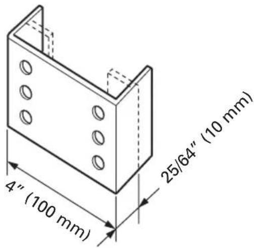
(1) Bending the sanding paper:
○ Position the sander with its pad side facing upward as shown in Fig. 8. Place the sanding paper on the pad so that the center of the sanding paper is aligned with the center of the pad, and bend both ends of the sanding paper at a 90° angle.
○Then, bend both ends again in the manner shown in Fig. 9. The sanding paper is now ready to be installed on the sander.

natural_image
Line drawing of hands operating a mechanical device with a tool (no text or symbols)Fig. 8 Fig. 9

text_image
4" (100 mm) 25/64" (10 mm)(2) Installing the sanding paper
While ensuring that the cord is not bent, place the sander on a workbench as shown in Fig. 10, and insert one end of the sanding paper (bent section). Next, insert the remaining bent section in the same manner.
CAUTION:
The sanding paper must be precisely installed on the pad, ensuring that there is ample tension (leaving no slack). Loosely installed sanding paper could result in unevenly sanded surfaces and/or damage to the sanding paper itself.
natural_image
Line drawing of hands using a tool to adjust or install a mechanical component (no text or symbols present)Fig. 10
[4-3/8" × 4" (110 × 100 mm) sanding paper (Velcro type)]
(1) Match the holes in the sanding paper (Velcro type) to the holes in the sponge pad (velcro type).

text_image
Sanding paper (Velcro type) Sponge pad (Velcro type)Fig. 11
(2) Surely attach the sanding paper (Velcro type) by strongly and evenly pressing with your palm. (Fig. 12)
Press strongly

natural_image
Line drawing of hands holding a small object with an arrow indicating downward motion (no text or symbols)Fig. 12
[5" (125 mm) quick stick sanding paper]
Attach the quick stick sanding paper to the 5" (125 mm) round rubber pad in the same way as shown in "6. Installing the sanding paper" on page 11.
- Opening holes in the sanding paper with the punch plate
Dust collecting capacity will improve if the punch plate is used to open holes in sanding paper without holes.
Punch plate
natural_image
Line drawing of a mechanical component with an arrow indicating rotation (no text or symbols)Fig. 13
MAINTENANCE AND INSPECTION

WARNING: Be sure to switch power OFF and disconnect the plug from the receptacle during maintenance and inspection.
- Emptying and cleaning the dust bag
If the dust bag contains too much saw dust, dust collection will be affected. Empty the dust bag when it gets full.
Remove the dust bag, open the fastener, and dispose of the contents.
- Inspecting the sanding paper
Since use of worn-out sanding paper will degrade efficiency and cause possible damage to the pad, replace the sanding paper as soon as excessive abrasion is noted.
- Inspecting the screws
Regularly inspect all screws and ensure that they are fully tightened. Should any of the screws be loosened, retighten them immediately.

WARNING: Using this orbital sander with loosened screws is extremely dangerous.
- Inspecting the carbon brushes
For your continued safety and electrical shock protection, carbon brush inspection and replacement on this tool should ONLY be performed by a HITACHI AUTHORIZED SERVICE CENTER.
- Service and repairs
All quality power tools will eventually require servicing or replacement of parts because of wear from normal use. To assure that only authorized replacement parts will be used, all service and repairs must be performed by a HITACHI AUTHORIZED SERVICE CENTER, ONLY.
- Service parts list

CAUTION: Repair, modification and inspection of Hitachi Power Tools must be carried out by an Hitachi Authorized Service Center.
This Parts List will be helpful if presented with the tool to the Hitachi Authorized Service Center when requesting repair or other maintenance. In the operation and maintenance of power tools, the safety regulations and standards prescribed in each country must be observed.
ACCESSORIES

WARNING:
ALWAYS use Only authorized HITACHI replacement parts and accessories. NEVER use replacement parts or accessories which are not intended for use with this tool. Contact HITACHI if you are not sure whether it is safe to use a particular replacement part or accessory with your tool. The use of any other attachment or accessory can be dangerous and could cause injury or mechanical damage.
NOTE:
Accessories are subject to change without any obligation on the part of the HITACHI.
STANDARD ACCESSORIES
(1) Sanding paper (quick stick type) (Grain: #80) (Code No. 310348) .... 1
(4-3/8" × 4" (110 mm × 100 mm))
(2) Dust bag (Code No. 323004)....1
OPTIONAL ACCESSORIES ...... sold separately
○Sanding paper
| Size Type Grit No. Code No. | |||
| 4-1/2" × 5-1/2"(114 mm × 140 mm) | Paper clip type AA | AA60 310341 | |
| 100 310342 | |||
| AA150 310343 | |||
| 4-3/8" × 4"(110 mm × 100 mm) | Velcro type AA10 | AA60 310344 | |
| 100 310345 | |||
| AA150 310346 | |||
| 4-3/8" × 4"(110 mm × 100 mm) | Quick stick type AA120 310350 | AA60 310347 | |
| AA80 310348 | |||
| AA100 310349 | |||
| AA150 310351 | |||
| AA180 310352 | |||
| 5" (125 mm) Velcro type AA60 310353 | |||
☐ Felt pad 4-3/8" × 4" (110 mm × 100 mm) (Code No. 310354)
○ Sponge pad (velcro type) 4-3/8" × 4" (110 mm × 100 mm) (Code No. 310355)
○ Round rubber pad 5" (125 mm) (Code No. 310356)
○Punch plate (Code No. 310340)
NOTE:
Specifications are subject to change without any obligation on the part of the HITACHI.
INFORMATIONS IMPORTANTES DE SÉCURITÉ
natural_image
Abstract black-and-white icon of a human head silhouette with a thermometer inside, no text or symbols present.natural_image
Silhouette of a helmet with a visor icon and arrow pointing to the head (no text or symbols)natural_image
Black and white illustration of a hand with a lightning bolt symbol (no text or numbers)⚠ AVERTISSEMENT:
natural_image
Line drawing of two hands assembling a diamond-shaped object with holes (no text or symbols)Fig. 2
natural_image
Line drawing of hands holding a mechanical component with an arrow indicating downward motion (no text or symbols)Fig. 4
natural_image
Line drawing of a hand using a power tool on a wooden surface (no text or symbols)Fig. 6
NOTE:
natural_image
Line drawing of hands using a tool to adjust or install a mechanical component (no text or symbols present)Fig. 8
text_image
4" (100 mm) 25/64" (10 mm)Fig. 9
natural_image
Line drawing of hands using a tool to adjust or install a mechanical component (no text or symbols present)Fig. 10
[Toile émeri de 4-3/8" × 4" (110 × 100 mm) (type Velcro)]
natural_image
Line drawing of hands holding a small electronic device with a downward arrow indicating compression (no text or symbols)Fig. 12
natural_image
Line drawing of a mechanical device with hands and a directional arrow indicating motion (no text or symbols)Fig. 13
natural_image
Abstract black-and-white icon of a human head silhouette with a thermometer and dot, no text or symbols present.natural_image
Silhouette of a helmet with a visor icon and arrow pointing to the head (no text or symbols)natural_image
Black and white illustration of a hand with a lightning bolt symbol (no text or numbers)ADVERTENCIA:
natural_image
Line drawing of hands holding a small electronic device with a downward arrow indicating force or motion (no text or symbols)Fig. 4

natural_image
Line drawing of a hand using a power tool on a wooden surface (no text or symbols)Fig. 6
OBSERVACION:
natural_image
Line drawing of hands holding a mechanical component with a tool, no text or symbols presentFig. 8

text_image
4"(100mm) 25/64"(10mm)Fig. 9
natural_image
Line drawing of hands using a tool to adjust or install a mechanical component (no text or symbols present)Fig. 10
[Papel de lija (tipo velcro) de 4-3/8" × 4" (110 mm × 100 mm)]
natural_image
Line drawing of a mechanical device being adjusted, showing internal components and a directional arrow (no text or symbols)text_image
Exploded view diagram of a mechanical assembly with numbered parts and exploded views for component identification.A B C D
1 — 1
2 301-653 4 D4 × 20
3 322-766 1
5 322-764 1
6 322-761 1
7 984-750 2 D4 × 16
8 937-631 1
9 — 1
10 953-327 1 D8.8
11 — 1
12 930-483 2
13 999-041 2
14 322-756 2
15 311-945 2 D4 × 10
16 322-759 1
17 311-978 1
18 949-216 4 M4 × 10
19 938-307 1
20 311-948 1
21 626-VVM 1 626VVC2PS2L
22 340-578D 1 120V
23 322-762 1
24 322-763 1
25 360-637U 1 120V "21, 26"
26 629-VVM 1 629VVC2PS2L
27 322-757 1
28 993-052 1
29 600-1DD 1 6001DDCMPS2L
30 987-169 1
31 993-244 1 M4 × 12
32 322-758 1
33 984-750 2 D4 × 16
34 311-946 1
35 322-760 2
501 323-004 1
502 310-348 1
503 310-340 1
WARNING:
Some dust created by power sanding, sawing, grinding, drilling, and other construction activities contains chemicals known [to the State of California] to cause cancer, birth defects or other reproductive harm. Some examples of these chemicals are:
- Lead from lead-based paints,
●Crystalline silica from bricks and cement and other masonry products, and
●Arsenic and chromium from chemically-treated lumber.
Your risk from these exposures varies, depending on how often you do this type of work. To reduce your exposure to these chemicals: work in a well ventilated area, and work with approved safety equipment, such as those dust masks that are specially designed to filter out microscopic particles.
AVERTISSEMENT:
Minato-ku, Tokyo 108-6020, Japan
Distributed by

Hitachi Koki U.S.A., Ltd.
3950 Steve Reynolds Blvd.
Norcross, GA 30093

Hitachi Koki Canada Co.
6395 Kestrel Road
Mississauga ON L5T 1Z5
402
Code No. C99129561
Printed in China