SPV33 - Water pump Ashland - Free user manual and instructions
Find the device manual for free SPV33 Ashland in PDF.

| Product Type | Sump Pump |
| Brand | Ashland |
| Model | SPV33 |
| Supply Voltage | 115 V |
| Electrical Protection | Ground Fault Circuit Interrupter recommended |
| Discharge Diameter | 1-1/2" |
| Max Liquid Temperature | 62.8 °C (145 °F) |
| Integrated Switch | Automatic Float Switch On/Off |
| Usage | Clear or wastewater (not potable water) |
| Materials | Bronze / brass (may contain lead) |
| Required accessories (not included) | 1-1/2" discharge pipe, 1-1/2" check valve, elbow, sealing tape |
| Thermal Protection | Yes (trips on overload) |
| Warranty | 3 years (limited) |
| Installation requirement | Hard, flat surface, no clay or gravel |
| Compatible piping type | ABS, PVC, polyethylene, galvanized steel |
| Maintenance | Clean the vent hole and intake regularly |
Frequently Asked Questions - SPV33 Ashland
User questions about SPV33 Ashland
0 question about this device. Answer the ones you know or ask your own.
Ask a new question about this device
Download the instructions for your Water pump in PDF format for free! Find your manual SPV33 - Ashland and take your electronic device back in hand. On this page are published all the documents necessary for the use of your device. SPV33 by Ashland.
USER MANUAL SPV33 Ashland
OPERATION, PERFORMANCE, SPECIFICATIONS and PARTS MANUAL
Heavy Duty Sump Pump
- Thank you for purchasing this pump. Take the time to read the instructions carefully before using this product. We strongly recommend that you keep this instruction manual in a safe place for future reference.
- Please refer to our website and the Products Center for additional installation and operation instructions.
• Refer to the website for replacement parts information.
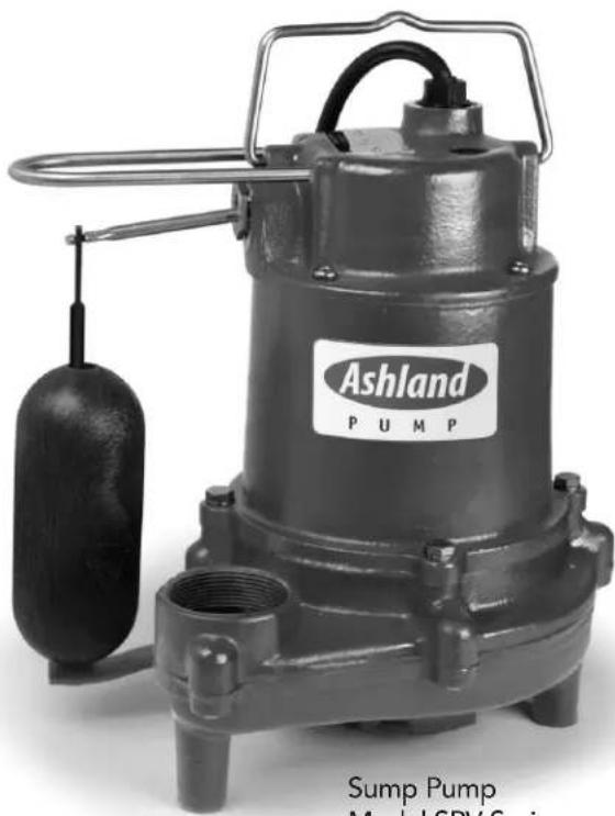
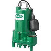
natural_image
Exterior view of a Ashland Pump model with visible branding and control handle (no text-heavy elements)Sump Pump Model SPV Series
MARKS AND MEANING:
DANGER
imminent hazardous situation
which, if not avoided, WILL result in death or serious injury.
"Warning" indicates an
WARNING Hazardous situation
which, if not avoided, MAY result in death or serious injury.
"Caution" indicates a
Potentially hazardous situation
which, if not avoided, MAY result in minor or moderate injury.

P U M P
Sump Pumps
Model: SPV Series
Specifications
Before installation, read the following instructions carefully. Failure to follow instruction and safety information could cause serious bodily injury, death and/or property damage. Each Ashland Pump is individually factory tested to ensure proper performance. Closely following these instructions will eliminate potential operating problems assuring years of trouble-free service.
Most accidents can be avoided by using common sense.
IMPORTANT - Ashland Pump is not responsible for losses, injury or death resulting from failure to observe these safety precautions, misuse, abuse or misapplication of pumps or equipment.
DANGER products must be recognized, or
decontaminated prior to shipment, to
everyone employees will not be exposed to health hazards in handling said materials.
All applicable laws and regulations shall apply.
Bronze/brass fitted pumps may contain lead levels higher than c
sidered safe for potable water systems. Government agencies have determined that leaded copper alloys should not be used in potable water applications.
⚠️WARNING] installation wiring, and junction connections must be in accord-
ance with the National Electric Code and all applicable state and local codes. Requirements may vary depending on usage and location.
⚠ WARNING Installation and servicing is to be conducted by qualified personnel only.
DANGER
Rotating machinery. Amputation or severe lacerations can

result. Keep clear of suction and discharge openings. DO NOT insert fingers into pump with power connected.
⚠️WARNING Always wear eye protection when working on pumps. Do not wear loose clothing that may become entangled in moving parts.
DANGER
Pumps build up heat and pressure during operation.
Allow time for pumps to cool before handling or servicing.
DANGER
Hazardous Voltage can shock, burn or cause death. This pump is

not intended for use in swimming pools or water installations where human contact with pumped fluid is possible.
DANGER
Risk of electrical shock. To

NGER reduce risk of electrical shock, always disconnect pump from power source before handling. Lock out power & tag.
⚠ WARNING Do Not use these pumps in water over 145°F. Do not exceed manufactures recommended maximum performance, as this could cause the motor to overheat.
CAUTION Make sure lifting handles are securely fastened each time before lifting.
DANGER Do not lift, carry or hang pump by the electrical cables. Damage to the electrical cables can cause shock, burns or death. Never handle connected power cords with wet hands. Use appropriate lifting device.
WARNING Sump and sewage pumps often handle materials which could cause illness or disease. Wear adequate protective clothing when working on a used pump or piping. Never enter a basin after it has been used.
⚠️ DANGER Failure to permanently ground the pump, motor and controls before connecting to power can cause shock, burns or death.
DANGER These pumps are NOT to be installed in locations classified as hazardous in accordance with the National Electric Code, ANSI/NFPA 70.
⚠ WARNING Do not introduce into any sewer, either directly, or through a kitchen waste disposal unit or toilet: Seafood Shells, Aquarium Gravel, Cat Litter, Plastic Objects, Sanitary Napkins or Tampons, Diapers, Rags, Disposable Wipes or Cloth, Medications, Flammable Material, Oil or Grease, Strong Chemicals, Gasoline.
- Operation against a closed discharge valve will cause premature bearing and seal failure on any pump.
- Any wiring of pumps should be performed by a qualified electrician.
- Cable should be protected at all times to avoid punctures, cuts, bruises, and abrasions-inspect frequently.
- Never handle connected power cords with wet hands.
- Never let cords or plugs lie in water outside the sump pit.
![305.6 [12.03] 248.1 [9.77]](/content/2026/04/642897/images/4f1a0480fd6a671f2f926431d061a8c1bd1ad8594d37833b64b21ff5557d0c74.jpg)
![215.6 [8.49] 266.8 [10.50] 1-1/2NPT](/content/2026/04/642897/images/08ec93dd79a18a77179833b0b7789d49a203ce62ffe4647b845bf09b30feb04a.jpg)
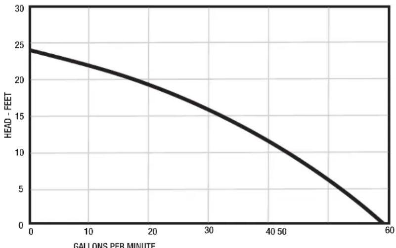
SPV33 PERFORMANCE
line
| GALLONS PER MINUTE | HEAD - FEET | | ------------------ | ----------- | | 0 | 24.5 | | 10 | 22.0 | | 20 | 19.0 | | 30 | 16.0 | | 40 | 12.0 | | 50 | 8.0 | | 60 | 0.0 |Performance Data
| Total Lift (feet) 0 | 5 10 | 15 20 | 24 | |||
| GPM | 58.5 | 51 | 44 | 31 | 17 |
0
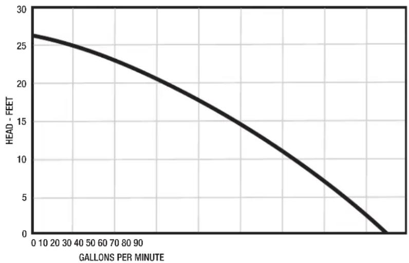
SPV50 PERFORMANCE
line
| GALLONS PER MINUTE | HEAD - FEET | | ------------------ | ----------- | | 0 | 26.5 | | 10 | 26.0 | | 20 | 25.5 | | 30 | 25.0 | | 40 | 24.5 | | 50 | 24.0 | | 60 | 23.5 | | 70 | 23.0 | | 80 | 22.5 | | 90 | 22.0 | | 100 | 21.5 | | 110 | 21.0 | | 120 | 20.5 | | 130 | 20.0 | | 140 | 19.5 | | 150 | 19.0 | | 160 | 18.5 | | 170 | 18.0 | | 180 | 17.5 | | 190 | 17.0 | | 200 | 16.5 | | 210 | 16.0 | | 220 | 15.5 | | 230 | 15.0 | | 240 | 14.5 | | 250 | 14.0 | | 260 | 13.5 | | 270 | 13.0 | | 280 | 12.5 | | 290 | 12.0 | | 300 | 11.5 | | 310 | 11.0 | | 320 | 10.5 | | 330 | 10.0 | | 340 | 9.5 | | 350 | 9.0 | | 360 | 8.5 | | 370 | 8.0 | | 380 | 7.5 | | 390 | 7.0 | | 400 | 6.5 | | 410 | 6.0 | | 420 | 5.5 | | 430 | 5.0 | | 440 | 4.5 | | 450 | 4.0 | | 460 | 3.5 | | 470 | 3.0 | | 480 | 2.5 | | 490 | 2.0 | | 500 | 1.5 | | 510 | 1.0 | | 520 | 0.5 | | 530 | 0.0 |Performance Data
| Total Lift (feet) 0 | 5 10 | 15 20 26 | ||||
| GPM | 85 74 | 63 | 47 | 31 |
0

Sump Pumps Model: SPV Series Installation
Pre-Installation
INSTALLATION REQUIREMENTS
- This pump is provided with an on/off float switch for automatic operation.
- Care should be taken to prevent the pump from running in a dry sump.
- The pump must be placed on a hard level surface. Never place the pump directly on clay or gravel surfaces.
- The pump can be installed with ABS, PVC, polyethylene or galvanized steel pipe. Proper adapters are required to connect plastic pipe to the pump.
- Install a union in the discharge line, just above the sump pit, to allow for easy removal of the pump for cleaning or repair.
- A check valve must be used in the discharge line to prevent back flow of liquid into the basin. The check valve should be a free flow valve that will easily pass solids.
- When a check valve is used, drill a relief hole 3/16" in diameter in the discharge pipe. This hole should be located below the floor line between the pump discharge and the check valve. Unless such a relief hole is provided, the pump could "air lock" and will not pump water even though it will run.
- A union and shut-off valve can follow the check valve to allow periodic cleaning of the check valve or removal of the pump.
- The remainder of the discharge line should be as short as possible with the minimum of turns to minimize friction head loss. Do not restrict the discharge to sizes below 2".
MATERIALS REQUIRED (NOT INCLUDED)
- 1-1/2" Discharge pipe
- Thread sealant tape
- 1-1/2" Check valve
- 1-1/2" Elbow
NOTE: The consumer/installer should purchase either a pre-threaded 1-1/2" MNPT pipe (or unthreaded pipe and pipe threader) or a 1-1/2" or 1-1/4" adapter (1-1/2" MNPT x 1-1/2" slip fit or 1-1/2" MNPT x 1-1/4" slip fit)
Service and Repair
Important: Pump should be thoroughly cleaned of trash and deposits before starting disassembly operations.

WARNING
Disconnect all power and control wires to motor at control panel before starting disassembly operation. Never rely on opening circuit breaker only.

CAUTION
Operating pump builds up heat and pressure; allow time for pump to cool to room temperature
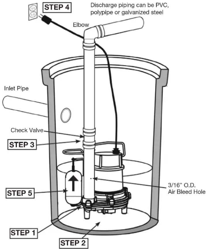
INSTALLATION
STEP 1:
Connecting the discharge pipe to the pump.
Wrap the threads of the 1-1/2" discharge pipe with thread sealant tape. Next attach the discharge pipe to the discharge of the pump.
STEP 2:
Place the pump in basin.
Place pump on a hard surface inside basin.
STEP 3:
Connecting the check valve.
Connect the discharge pipe to the check valve, another section of vertical pipe, elbow, and optional to connect union and shut-off valve after elbow.
OPERATION
STEP 4
Connecting power
Plug the power cord into a 115V GFCI power outlet. Allow pump to operate through several on-off cycles by adding water to basin.
STEP 5
Operating the pump
When the float switch moves up over the top of the pump, the pump begins to operate. When the water lowers to a certain level, the float switch will turn the pump off.
Always disconnect the pump from the electrical power source before handling. If the system fails to operate properly, carefully read instructions and perform maintenance recommendations. If operating problems persist, the following chart may be of assistance in identifying and correcting them.
SYMPTOM POSSIBLE CAUSES CORRECTIVE ACTION
| Pump runs but does 1. Pump impeller maybe air locked 1. Purge air not pump liquid 2. Vent hole clogged 2. Clean out the vent hole3. Clogged inlet 3. Clean out the inlet4. Discharge gate valve may be closed 4. Open gate valve5. Discharge check valve may be clogged or have a broken clapper freedom of operation6. Discharge head may be too high | ||
| Thermal overload trips | 1. Impeller may be clogged with foreign objects cavity and inlet of any | 1. Check impeller for freedom of operation, security and condition. Clean impeller obstruction |
| Circuit breaker trips short in the motor2. If this condition happens after an | 1. Excessive load possibly caused by a2. Reset breaker. electrical storm, motor or control box may be damaged by lightning | 1. Contact qualified technicianIf breaker trips again in a few seconds check motor for lightning damage |

Sewage Pumps Model: SPV33, SPV50 Series Warranty
For a period of time no greater than three (3) years after the original purchase of the subject product, and subject to the conditions of this Limited Warranty, Ashland Pump will repair or replace for the original purchaser only, any portion of your new Ashland Pump product that proves to contain defective materials or defective workmanship, provided the product is properly installed, serviced and operated under normal conditions and according to the manufacturer's instructions. Ashland Pump disclaims all liability, including liability under this Limited Warranty, for improper installation, application or use of its products. Ashland Pump shall have and possess the sole discretion to determine whether to repair or replace defective equipment, parts or components with a new or remanufactured part. Any item to be replaced under this Warranty must be returned to Ashland Pump, or such other place as Ashland Pump may designate, freight prepaid. In the absence of suitable proof of purchase date, the effective date of this warranty will be based upon the date of manufacture as evidenced by the serial number of the product.
There is no other express or implied warranty covering your Ashland Pump product. Without limiting the foregoing, Ashland Pump specifically disclaims the implied warranties of merchantability and fitness for a particular purpose. No warranties or representations at any time made by any representative of Ashland Pump shall vary or expand the provisions of this written Limited Warranty. This Limited Warranty contains the purchaser's exclusive remedy for any alleged defect in the product.
To the greatest extent permissible by applicable law, Ashland Pump shall not be liable or responsible for consequential, incidental or special damages resulting from or related in any manner to any Ashland Pump product or parts. Personal injury and/or property damage may result from improper installation, application or use of your Ashland Pump product. Ashland Pump shall not be liable for any loss, damage, or expenses resulting from the installation or use of its products other than as expressly set forth in this Limited Warranty. Ashland Pump shall in no event be responsible or liable for the cost of field labor or other charges incurred by any purchaser or user in removing and/or reaffixing any Ashland Pump product, part or component or any temporary pumping or other equipment. Some states do not allow the exclusion or limitation of incidental or consequential damages, so the above limitation or exclusion may not apply to you.

P U M P
Honest, Professional, Dependable
1899 Cottage Street, Ashland, Ohio 44805 Telephone: 855 281-6830 • Fax: 877 326-1994 ashlandpump.com
Ashland
P U M P
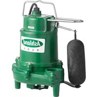
natural_image
Industrial water pump with attached piping and valve, labeled Ashland PUMP (no text on pump body)Bomba de Sumidero Modele Serie SPV

P U M P
Bombas de sumidero
Modelo: Serie SPV
Especificaciones
Bombas de sumidero
Modelo: Serie SPV
Especificaciones
![305.6 [12.03] 248.1 [9.77]](/content/2026/04/642897/images/cc6e65d7166f399787891b5ece229f19c9a116072e12adb369b19724b77124e1.jpg)
![215.6 [8.49] 266.8 [10.50] 1-1/2NPT](/content/2026/04/642897/images/d2551b7d0744d78629637c560d67547a50fabd36b91002b6bb8ff252158c1140.jpg)
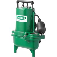
natural_image
Exterior view of a Ashland Pump with visible branding and control panel (no text-heavy elements)Pompes de puisard
Modèle : Série SPV
Spécifications
![305.6 [12.03] 248.1 [9.77]](/content/2026/04/642897/images/fd0480d7c39c54ec2df9e3e1c840c8bdf21e57848ea93e243903501629f0495c.jpg)
![215.6 [8.49] 266.8 [10.50] 1-1/2NPT](/content/2026/04/642897/images/a99e2289f79f0dceb8131ca9f5fda237ea2a460290ec953cda4e8e5ad9ffb237.jpg)
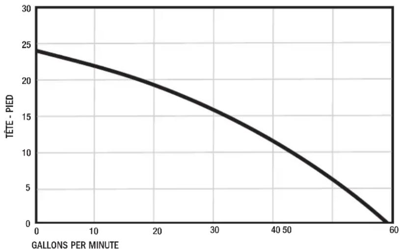
PERFORMANCE DE SPV33
line
| GALLONS PER MINUTE | TÊTE - PIED | | ------------------ | ----------- | | 0 | 24.5 | | 10 | 22.5 | | 20 | 19.5 | | 30 | 16.0 | | 40 | 11.5 | | 50 | 7.0 | | 60 | 0.0 |Performance
| Total Lift (feet) 0 | 5 10 | 15 20 | 24 | |||
| GPM | 58.5 | 51 | 44 | 31 | 17 |
0
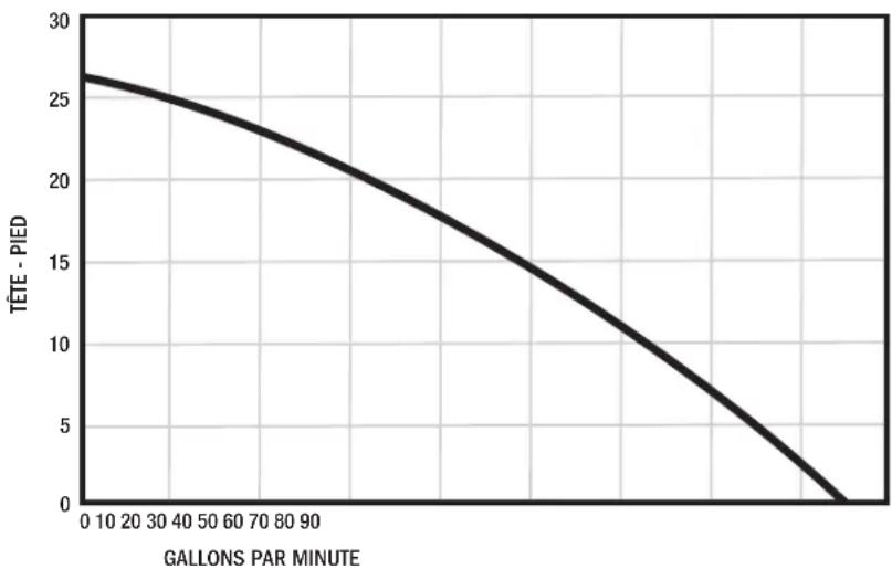
PERFORMANCE DE SPV50
line
| Gallons Par Minute | TÊTE - PIED | | ------------------ | ----------- | | 0 | 26.5 | | 10 | 26.0 | | 20 | 25.5 | | 30 | 25.0 | | 40 | 24.5 | | 50 | 24.0 | | 60 | 23.5 | | 70 | 23.0 | | 80 | 22.5 | | 90 | 22.0 | | 100 | 21.5 | | 110 | 21.0 | | 120 | 20.5 | | 130 | 20.0 | | 140 | 19.5 | | 150 | 19.0 | | 160 | 18.5 | | 170 | 18.0 | | 180 | 17.5 | | 190 | 17.0 | | 200 | 16.5 | | 210 | 16.0 | | 220 | 15.5 | | 230 | 15.0 | | 240 | 14.5 | | 250 | 14.0 | | 260 | 13.5 | | 270 | 13.0 | | 280 | 12.5 | | 290 | 12.0 | | 300 | 11.5 | | 310 | 11.0 | | 320 | 10.5 | | 330 | 10.0 | | 340 | 9.5 | | 350 | 9.0 | | 360 | 8.5 | | 370 | 8.0 | | 380 | 7.5 | | 390 | 7.0 | | 400 | 6.5 | | 410 | 6.0 | | 420 | 5.5 | | 430 | 5.0 | | 440 | 4.5 | | 450 | 4.0 | | 460 | 3.5 | | 470 | 3.0 | | 480 | 2.5 | | 490 | 2.0 | | 500 | 1.5 | | 510 | 1.0 | | 520 | 0.5 | | 530 | 0.0 |Performance
| Total Lift (feet) | 0 | 5 | 10 | 15 | 20 | 26 | |||
| GPM | 85 | 74 | 63 | 47 | 31 |
0

Pompes de puisard
Modèle : Série SPV
l'installation
SYMPTÔME CAUSES POSSIBLES ACTION CORRECTIVE
1899 Cottage Street, Ashland, Ohio 44805, USA