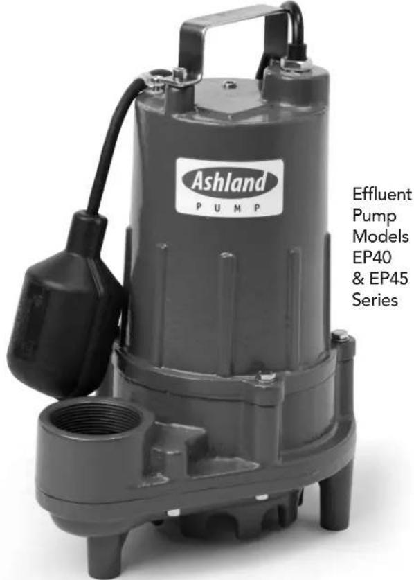
EP45 - Water pump Ashland - Free user manual and instructions
Find the device manual for free EP45 Ashland in PDF.

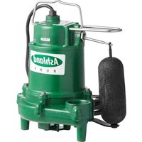
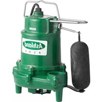
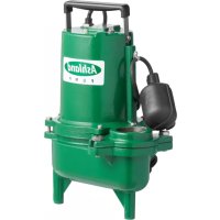
| Product Type | Effluent Water Pump |
| Brand | Ashland |
| Model | EP45 |
| Supply Voltage | 115 V or 230 V (single phase) |
| Rated Current | 11 A (115 V) or 5.5 A (230 V) |
| Motor Power | 1/2 HP (0.37 kW) |
| Impeller Type | Cast Iron Vortex |
| Body Material | Cast Iron |
| Volute Material | Cast Iron |
| Shaft Material | Stainless Steel |
| Discharge Size | 2" NPT |
| Max Solid Size | 3/4" (19 mm) |
| Cable Length | 20 ft (6 m) |
| Thermal Protection | Yes (built-in thermal sensor) |
| Recommended Use | Domestic, commercial, and light industrial wastewater |
| Installation Type | Submersible in a sump pit |
| Dimensions (L x W x H) | 24.9 x 17.8 x 34.8 cm |
| Recommended Maintenance | Check oil level and clean impeller |
| Warranty | 3 years (defective parts) |
Frequently Asked Questions - EP45 Ashland
User questions about EP45 Ashland
0 question about this device. Answer the ones you know or ask your own.
Ask a new question about this device
Download the instructions for your Water pump in PDF format for free! Find your manual EP45 - Ashland and take your electronic device back in hand. On this page are published all the documents necessary for the use of your device. EP45 by Ashland.
USER MANUAL EP45 Ashland
OPERATION, PERFORMANCE, SPECIFICATIONS and PARTS MANUAL
EP40 & EP45 4/10 & 1/2 HP Effluent Pumps
- Thank you for purchasing this pump. Take the time to read the instructions carefully before using this product. We strongly recommend that you keep this instruction manual in a safe place for future reference.
- Please refer to our website and the Products Center for additional installation and operation instructions and replacement parts information.
MARKS AND MEANING:
DANGER ttes an
immnent nucious situation
which, if not avoided, WILL result in death or serious injury.
WARNING "Warning" indicates an imminent hazardous situation which, if not avoided, MAY result in death or serious injury.
CAUTION "Caution" indicates a potentially hazardous situation which, if not avoided, MAY result in minor or moderate injury.

Effluent Pumps Model: EP40 & EP45 Series General Safety Information
Before installation, read the following instructions carefully. Failure to follow instruction and safety information could cause serious bodily injury, death and/or property damage. Each Ashland Pump is individually factory tested to ensure proper performance. Closely following these instructions will eliminate potential operating problems assuring years of trouble-free service.
Most accidents can be avoided by using common sense.
IMPORTANT - Ashland Pump is not responsible for losses, injury or death resulting from failure to observe these safety precautions, misuse, abuse or misapplication of pumps or equipment.
DANGERducts mustitized, or
decontaminated prior to shipment, to
in some employees will not be exposed to
health hazards in handling said materials.
All applicable laws and regulations shall apply.
AWARNTING fitted pumps may contain lead levels higher than o
sidered safe for potable water systems. Government agencies have determined that leaded copper alloys should not be used in potable water applications.
AWARNING ing, and junction connections must be in accord
ance with the National Electric Code and all applicable state and local codes. Requirements may vary depending on usage and location.
WARNING
Installation and servicing is to be conducted by qualified personnel only.
DANGER
Rotating machinery, amputation or severe lacerations can result.

Keep clear of suction and discharge openings. DO NOT insert fingers into pump with power connected.
WARNING
wear eye protection when
clothing that may become entangled in moving parts.
DANGER
Pumps build up heat and pressure during operation
Allow time for pumps to cool before handling or servicing.
DANGER
Hazardous Voltage can shock, burn or cause death. This pum

not intended for use in swimming pools or water installations where human contact with pumped fluid is possible.
DANGER
Risk of electrical shock. To reduce risk of electrical shock,

always disconnect pump from source before handling. Lock out power & tag.
WARNING
Do Not use these pumps in water over 145^ . Do not exceed manu
factures recommended maximum performance, as this could cause the motor to overheat.
CAUTION
Make sure lifting handles are securely fastened each time before lifting.
DANGER
Do not lift, carry or hang pump by the electrical cables. Damage to

the electrical cables can cause shock, burns or death. Never handle connected power cords with wet hands. Use appropriate lifting device.
WARNING
Effluent pumps often handle materials which could cause illness, inadequate protective clothing when a pump or piping. Never enter a basin used.
DANGER
Failure to permanently ground the pump, motor and controls before

connecting to power can cause shock, burns or death.
DANGER
These pumps are NOT to be in locations classified

as hazardous in accordance with the National Electric Code, ANSI/NFPA 70.
WARNING
Do not introduce into any sewer, either directly, or through a kitchen
waste disposal unit or toilet: Seafood Shells, Aquarium Gravel, Cat Litter, Plastic Objects, Sanitary Napkins or Tampons, Diapers, Rags, Disposable Wipes or Cloth, Medications, Flammable Material, Oil or Grease, Strong Chemicals, Gasoline.
Operation against a closed discharge valve will cause premature bearing and seal failure on any pump.
- Any wiring of pumps should be performed by a qualified electrician.
- Cable should be protected at all times to avoid punctures, cuts, bruises, and abrasions-inspect frequently.
- Never handle connected power cords with wet hands.
- Never let cords or plugs lie in water outside the sump pit.
- These pumps are offered in a three phase and single phase wiring configuration. Voltages will vary according to the application and can be seen in the tables in this manual.

Effluent Pumps Model: EP40 & EP45 Series Specifications
| IMPORTANT Prior to installation, record Model Number, MFG Date, Amps, Voltage, Phase and HP, from pump nameplate for future reference. Also record the voltage and current readings at startup: | 1 Phase Models | Model Number: MFG Date: HP: SN: | |
| Amps: Volts: | |||
SPECIFICATIONS
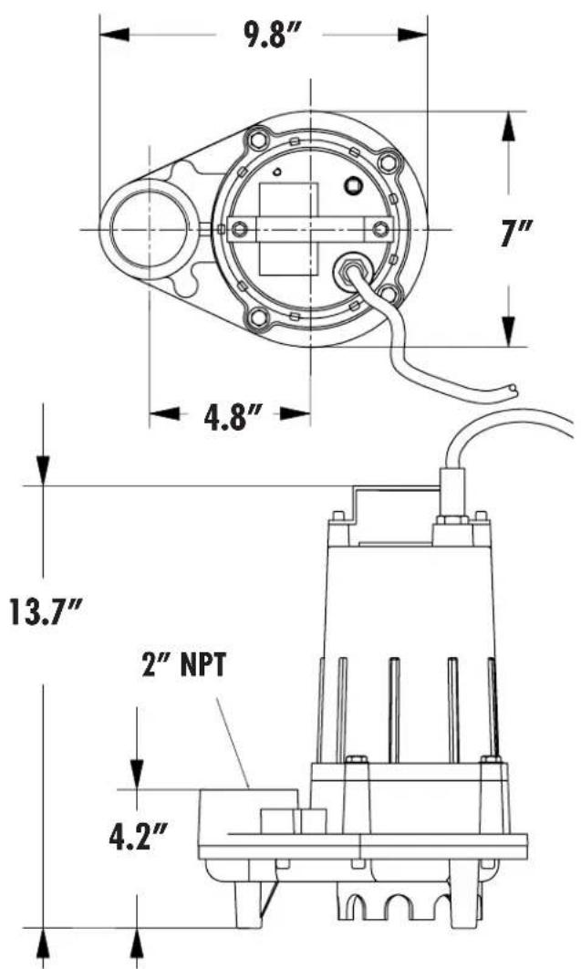
| Model | HP | Volt | Ph | Amps | Overall Size (inches) | Pump Material Motor | |||||
| L | W | H | Volute | Housing | Impeller | Shaft | |||||
| EP40M1-20 | 4/10 | 115 | 1 | 9.0 | 9.8 | 7 | 13.7 | Cast Iron | Cast Iron | Cast Iron | SS |
| EP40M2-20 | 4/10 | 230 | 1 | 4.5 | 9.8 | 7 | 13.7 | Cast Iron | Cast Iron | Cast Iron | SS |
| EP45M1-20 | 1/2 | 115 | 1 | 11.0 | 9.8 | 7 | 13.7 | Cast Iron | Cast Iron | Cast Iron | SS |
| EP45M2-20 | 1/2 | 230 | 1 | 5.5 | 9.8 | 7 | 13.7 | Cast Iron | Cast Iron | Cast Iron | SS |
Note: All dimensions have a tolerance of +1/8
Description: To pump domestic, commercial and light industrial sewage
Physical Data:
DISCHARGE SIZE 2" NPT
IMPELLER TYPE Vortex, Cast Iron
CABLE LENGTH 20
Liquid Handling:
SOLIDS SIZE 3/4"
ACCEPTABLE PH RANGE 6-8
Temperature:
MAXIMUM STATOR 130^
MAXIMUM LIQUID TEMP. 104°F - Intermittent
Technical Data:
POWER CORD TYPE SJTW 16/3C
MOTOR HOUSING Cast Iron
VOLUME Cast Iron
IMPELLER Cast Iron
MOTOR SHAFT 416SST
HARDWARE SST
"O RINGS NBR
SEALS Single Mechanical
Carbon Ceramic
UPPER BEARING 6000
LOWER BEARING 6203

Effluent Pumps
Model: EP40 & EP45 Series
Specifications and Performance
SPECIFICATIONS
| Model HP Hz Volts/Ph RPM Full Load Nema Start Cord Cord Cord Amps Code Type Size O.D. | |||||||||
| EP40M1-20 | 4/10 | 60 | 115 | 3450 | 9.0 | P | SJTW | 16AWG/3C | .34 |
| EP40M2-20 | 4/10 | 60 | 230 | 3450 | 4.5 | P | SJTW | 16AWG/3C | .34 |
| EP45M1-20 | 1/2 | 60 | 115 | 3450 | 11.0 | P | SJTW | 16AWG/3C | .34 |
| EP45M2-20 | 1/2 | 60 | 230 | 3450 | 5.5 | P | SJTW | 16AWG/3C | .34 |
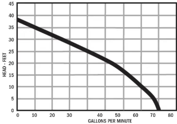
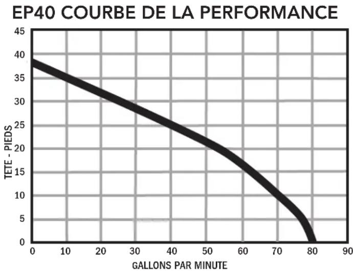
EP40 PERFORMANCE CURVE
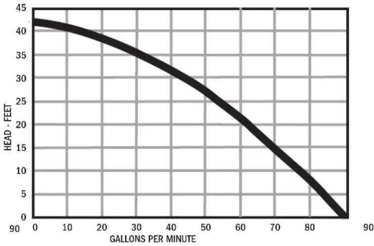
EP45 PERFORMANCE CURVE
EP40 PERFORMANCE CHART
| Total Lift(feet) | 0 | 5 | 10 | 15 | 20 | 25 | 30 | 37 |
| GPM | 80 | 75 | 70 | 62 | 53 | 42 | 27 | 0 |
EP45 PERFORMANCE CHART
| Total Lift(feet) | 0 | 5 | 10 | 15 | 20 | 25 | 30 | 40 | 42 |
| GPM | 90 | 83 | 76 | 69 | 61 | 52 | 42 | 12 | 0 |

Effluent Pumps Model: EP40 & EP45 Series Receiving and Installation
Receiving Inspection
Upon receiving the pump, it should be inspected for damage or shortages. If damage has occurred, file a claim immediately with the company that delivered the pump. If the manual is removed from the packaging, do not lose or misplace.
Storage
Any product that is stored for a period longer than six (6) months from the date of purchase should be bench tested prior to installation. A bench test consists of, checking the impeller to assure it is free turning and a run test to assure the motor (and switch if provided) operate properly. Do not pump out of liquid.
WARNING clearance under the pump to entrance of sewage solids must be a minimum of 2 inches to a maximum of 3.5 inches.
Submergence
The pump should always be operated in the submerged condition. The minimum sump liquid level should never be less than above the pump's motor (see fig. 1), unless very briefly.
Installation
The sump or basin shall be sealed and vented in accordance with local plumbing codes. This pump is designed to pump domestic wastewater, nonexplosive and noncorrosive liquids and shall NOT be installed in locations classified as hazardous in accordance with the National Electrical Code (NEC) ANSI/ NFPA 70 or Canadian Electric Code
(CEC). The pump
should never be installed in a trench, ditch, or hole with a dirt bottom.
The legs will sink into the dirt and the suction will become plugged.
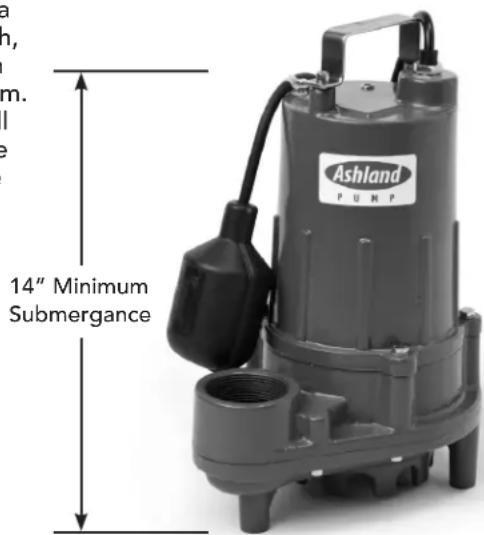
FIGURE 1
Discharge Piping
Install discharge piping or hose assembly to the pump. Discharge piping should be as short as possible and sized no smaller than the pump discharge. Do not reduce the discharge pipe size below that which is provided on the pump. Both a check valve and a shut-off valve are recommended for each pump. The check valve is used to prevent backflow into the sump. The shut-off valve is used to manually stop system flow during pump servicing. Be sure the discharge pipe has a 1/8'' diameter hole approx. 5'' from end nearest volute and oriented towards the pump body.
Control Panel
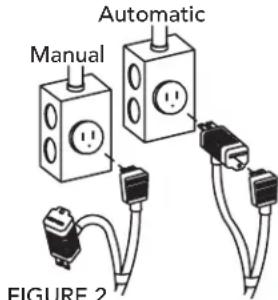
Single phase series effluent pumps DO NOT require a control panel, but do require a level control with a piggy back plug, see "Piggy-back Plug, figure 2" below.
Motor: Each motor is provided with heat sensor thermostats attached directly to the motor windings. The thermostats open if the motor windings see excessive heat and, in turn, open the motor contactor in the control panel when used, breaking the power to the pump. When the motor is stopped due to an overheated condition, it will not start until the motor has cooled.
Pre-operation
CHECK VOLTAGE AND PHASE
Before operating pump, check to make sure that voltage and phase information stamped on the pump's identification plate matches the available power.
CHECK PUMP ROTATION
Before putting pump into service for the first time, the motor rotation must be checked. Improper motor rotation can result in poor pump performance and can damage the motor and/or pump.
IDENTIFICATION PLATE
Note the numbers on the pumps identification plate and record in this manual for future reference.
Electrical Connections

Always rely upon a Certified Electrician for installation.
Piggy-Back Plug Plug the level control plug into a 115V receptacle, then plug the pump into the piggy-back plug (See Figure 2). It is recommended that this circuit have a 15 AMP breaker. One cycle of operation should be observed, so that any potential problems can be corrected.

Effluent Pumps Model: EP40 & EP45 Series Receiving and Installation
It is recommended that the level control float should be set to insure that the liquid in the sump never drops below the top of the motor housing. The level control should have adequate clearance so it cannot hang up in it's swing and that the pump is completely submerged when the level control is in the "Off" mode. Minimum tether length is 3.50^ .
By adjusting the cord tether the control level can be changed. DO NOT USE THE POWER CABLE TO LIFT PUMP.
Pump-Down Test - Be sure pump has been plugged in, lowered into the basin or sump, check the system by filling with liquid and allowing the pump to operate through its pumping cycle. The time needed to empty the system, or pump-down time along with the volume of water, should be recorded.
Thermal Protection
The normally closed (N/C) over temperature sensor is embedded in the motor windings and will detect excessive heat in the event an overload condition occurs. The thermal sensor will trip when the windings become too hot and will automatically reset when the pump motor cools to a safe temperature.
In the event of an over temperature, the source of this condition should be determined and repaired immediately. Thermal protection shall not be used as a motor overload device.
Maintenance
Minimal maintenance is required. Perform the following checks when pump is removed from operation or when pump performance deteriorates:
a). Inspect motor chambers for oil level and contamination.
b). Inspect impeller and body for excessive build-up or clogging.
c). Inspect motor and bearings.
d). Inspect seal for wear or leakage.
Servicing
Cooling Oil - Anytime the pump is removed from operation, the cooling oil in the motor housing should be checked visually for oil level and contamination. To check oil, set unit upright. Remove pipe plug from housing.
With a flashlight, visually inspect the oil in the housing to make sure it is clean and clear, light amber in color and free from suspended particles. Milky white oil indicates the presence of water. Oil level should be just above the motor when pump is in vertical position.
Oil Testing
- Drain oil into a clean, dry container by placing pump on it's side. Remove pipe plug, from housing.
-
Check oil for contamination using an oil tester with a range to 30 Kilovolts breakdown.
If oil is found to be clean and uncontaminated (measuring above 15KV breakdown), refill the housing. -
If oil is found to be dirty or contaminated (or measures below 15 KV. breakdown), the pump must be carefully inspected for leaks at the shaft seal, cable assembly, o-ring and pipe plug, before refilling with oil. To locate the leak, perform the following pressure tests.
After leak is repaired, dispose of old oil properly, and refill with new oil.
Pressure builds up extremely fast, increase pressure by "TAPPING" air nozzle. Too much pressure will damage seal. DO NOT exceed 10 P.S.I.
Motor Housing Pressure Test:
If oil has been drained, fill to normal level before performing pressure test. Remove pipe plug from motor housing.
Apply pipe sealant to pressure gauge assembly and tighten into hole. Pressurize motor housing to 10 P.S.I. Use soap solution around the sealed areas above the oil level and inspect joints for "air bubbles". For sealed areas below oil level, leaks will seep oil. If, after five minutes, the pressure is still holding constant, and no "bubbles" / oil seepage is observed, slowly bleed the pressure and remove the gauge assembly. Replace oil. Leak must be located and repaired if pressure does not hold.
Oil Replacement Motor Housing
Remove pipe plug from motor housing.
Drain all oil (if not already done so) from motor housing and dispose of properly per Local Code. Set pump upright and refill with new cooling oil, see "Cooling Oil" chart. Fill to just above motor (.9L) as an air space must remain in the top of the motor housing to compensate for oil expansion. Apply pipe thread compound to threads of pipe plug then assemble to motor housing. Check that o-ring is in place and does not need to be replaced. Reassemble cord cap to motor housing.

DO NOT overfill oil. Overfilling of housing oil can create excessive and dangerous hydraulic pressure which can destroy the pump and create a hazard. Overfilling avoids warranty.
WARNING Before any service work is done, disconnect and lock electrical power to pump.
| Cooling Oil Recommended Supplier/Grade | |
| BP | Enerpar SE100 |
| Conoco | Pale Paraffin 22 |
| Mobile | D.T.E. Oil Light |
| Shell Canada | Transformer-10 |
| Texaco | Diala-Oil-AX |


Effluent Pumps Model: EP40 & EP45 Series Installation and Service
Volute - Remove socket head cap screws from volute.
Impeller - Remove impeller by turning counter-clockwise; careful application of heat may be necessary. Do Not store pump without impeller in place.
Seal- Handle seal parts with care. Remove rotating member from shaft. Remove pressed-in spring component from seal plate. Examine all seal parts. Inspect contact faces for signs of uneven wear tracks on stationary face, chips and scratches on either seal face. DO NOT interchange seal components, replace the entire shaft seal if necessary.
Seal Plate - Remove cap screws from seal plate. Remove seal plate and o-ring.
Bearings - Using a bearing puller or arbor press remove bearing from shaft. Remove upper motor bearing from shaft with a bearing puller.

REASSEMBLY
Bearing - Be careful not to damage the rotor shaft when replacing bearing. Using an arbor press, hold the rotor and press the upper bearing on the rotor shaft, applying force to the inner race of the bearing only. In the same manner replace lower bearing (49) onto rotor shaft.
Seal Plate - Lubricate and set o-ring in bottom of seal plate. Place seal plate over shaft, being sure o-ring is not twisted and in the groove. Place four capscrews through holes in motor housing and into seal plate and torque to 6.5 ft/lbs.
Outer Seal - Clean and oil stationary seal cavity in seal plate. Slide seal guide tool over motor shaft. Lightly oil (Do not use grease) outer surface of seal's stationary member.
Press stationary firmly into seal plate using a seal pusher tool. Be sure the stationary member is in straight. Nothing but the seal tool is to come in contact with seal face.

IMPORTANT! Do not hammer on the seal her. It will damage the seal face.
With lapped surface of rotating member facing inward toward stationary, slide rotating member and onto shaft, until lapped faces of stationary and rotating seal are together.
Impeller - Place impeller on motor shaft by turning clockwise. Blue thread locking compound is recommended.
Volute - Place volute on seal plate. Place socket head cap screws through volute and into seal plate Then torque evenly to 11 ft/lbs.

Effluent Pumps Model: EP40 & EP45 Series Installation and Service
Installing Pump in BASIN
Install pump in properly vented basin according to local codes and regulations. PVC pipe along with plastic check valve and shut-off valve are recommended. Drill a 1/8'' hole in the discharge pipe below the check valve. Install check valve 12'' above pump discharge. See Figure 3
Starting Pump After Installing in Basin
Before lowering pump into basin, connect power lines and start motor. Impeller should turn counterclockwise when looking at impeller.
Service and Repair
Important: Pump should be thoroughly cleaned of trash and deposits before starting disassembly operations (pages 6-8).
WARNING
Disconnect all power and control wires to motor at control panel before starting disassembly operation. Never rely on opening circuit breaker only.
CAUTION
Operating pump builds up heat and pressure; allow time for pump to cool to room temperature
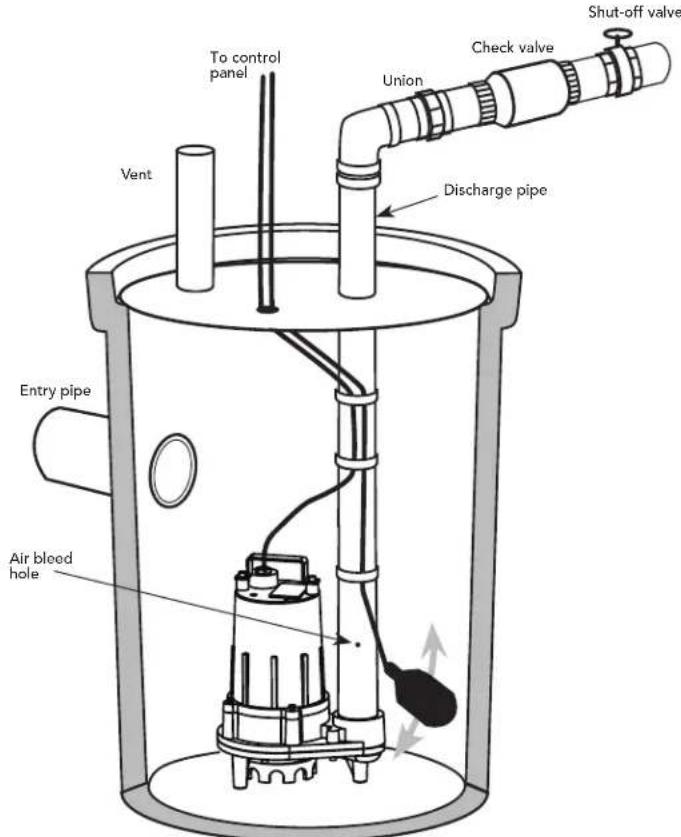
FIGURE 3
| PROBLEMS | POSSIBLE CAUSES/SOLUTIONS |
| PUMP DOES NOT RUN AND MAKES HUMMING SOUND | ·Line circuit breaker is off, or fuse is blown or loose ·Water level in sump has not reached turn-on level as indicated in installation drawing. ·Pump cord is not making contact in receptacle. ·Float is stuck. It should operate freely in basin. ·If all of the above are OK, then the motor could be malfunctioning. |
| PUMP RUNS BUT DOES NOT DELIVER WATER | ·Check if valve is installed backwards. Arrow on valve should point direction of flow ·Discharge shut-off valve (if used) may be closed. ·Impeller or volute openings are fully or partially clogged. Remove pump and clean. ·Pump is air-locked. Start and stop several times by plugging and unplugging cord. Check for clogged vent hole in pump case. ·Inlet holes in pump base are clogged. Remove pump and clean the openings. ·Vertical pumping distance is too high. Reduce distance or change the discharge fittings of the pump. |
| PUMP RUNS AND PUMPS OUT SUMP, BUT DOES NOT STOP | ·Float is stuck in up position. Be sure float operates freely in basin. ·Defective float switch. Replace float switch. |
| PUMP RUNS BUT ONLY DELIVERS A SMALL AMOUNT OF WATER | ·Pump is air-locked. Start and stop several times by plugging in and unplugging cord. Check for clogged vent hole in pump case. ·Vertical pumping distance is too high. Reduce distance or change the discharge fitting of the pump. Inlet holes in pump base are clogged. Remove pump and clean the strainer and openings. ·Impeller or volute openings are fully or partially clogged. Remove pump and clean. ·Pump impeller is partially clogged with tar or paint, causing motor to run slow and overload. Remove pump and clean. |
| FUSE BLOWS OR CIRCUIT BREAKER TRIPS WHEN PUMP STARTS | ·Pump impeller is partially clogged causing motor to run slow and overload. Remove pump and clean. ·Motor stator may be defective. ·Fuse size or circuit breaker may be too small. (must be 15 amps). ·Impeller or volute opening are fully or partially clogged. Remove pump and clean. |
| MOTOR RUNS FOR A SHORT TIME, THEN STOPS | ·Inlet holes in pump base are clogged. Remove pump and clean the openings. ·Pump impeller is partially clogged causing motor to run slow and overload. Remove pump and clean. ·Motor stator may be defective. ·Impeller or volute openings are fully or partially clogged. Remove pump and clean. Also clean the strainer if one is installed. |
ELECTRICAL PRECAUTIONS
AWARNING
then unplug the pump. Make sure you are not standing in water and are wearing insulated protective sole shoes, under flooded conditions. Contact your local electric company or a qualified licensed electrician for disconnecting electrical service prior to pump removal
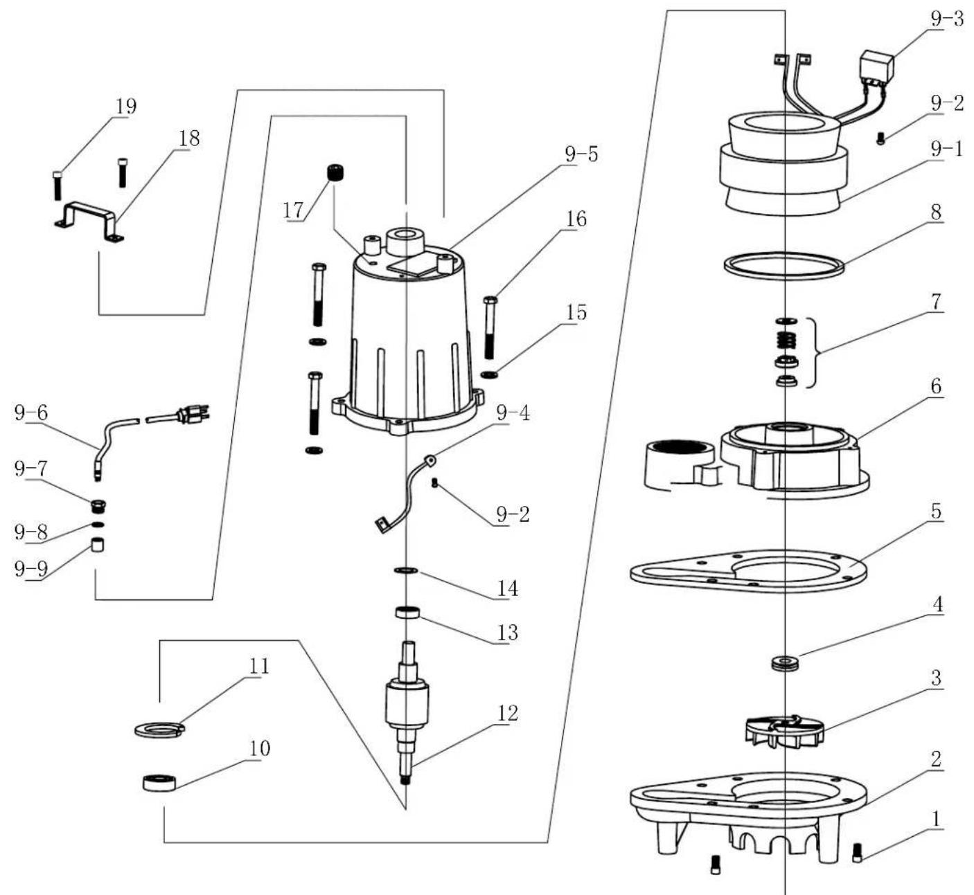
| No. Description Part No. QUANTITYEP40 EP45 | |||
| 1 | SCREW 091EP4001 6 6 | ||
| 2 | VOLUTE 091EP4002 1 1 | ||
| 3 | IMPELLER | 091EP4003 | 1 |
| IMPELLER | 091EP4503 | ||
| 4 | V-RING | 091EP4004 | 1 1 |
| 5 | GASKET | 091EP4005 | 1 1 |
| 6 | SEAL PLATE | 091EP4006 | 1 1 |
| 7 | SHAFT SEAL | 091EP4007 | 1 1 |
| 8 | O-RING 091EP4008 1 1 | ||
| 9-1 | STATOR ASSY | 091EP4009 | 1 1 |
| 9-2 | SCREW | 2 | |
| 9-3 | CAPACITOR | 1 1 | |
| 9-4 | GROUND LINE | 1 1 | |
| 9-5 | MOTOR HOUSING | 1 1 | |
| 9-6 | POWER CORD | 1 1 | |
| 9-7 | NUT | 1 | |
| 9-8 | WASHER | 1 | |
| 9-9 | O-RING | 1 | |
| 10 | BEARING | 091EP4018 | 1 1 |
| 11 | SNAP RING | 091EP4019 | 1 1 |
| 12 | ROTOR ASSY | 091EP4020 | 1 1 |
| 13 | BEARING | 091EP4021 | 1 1 |
| 14 | SPRING WASHER | 091EP4022 | 1 1 |
| 15 | WASHER | 091EP4023 | - - |
| 16 | SCREW | 091EP4024 | - - |
| 17 | PLUG | 091EP4025 | 1 1 |
| 18 | HANDLE | 091EP4026 | 1 1 |
| 19 | SCREW 091EP4027 2 | 2 | |
For a period of time no greater than three (3) years after the original purchase of the subject product, and subject to the conditions of this Limited Warranty, Ashland Pump will repair or replace for the original purchaser only, any portion of your new Ashland Pump product that proves to contain defective materials or defective workmanship, provided the product is properly installed, serviced and operated under normal conditions and according to the manufacturer's instructions. Ashland Pump disclaims all liability, including liability under this Limited Warranty, for improper installation, application or use of its products. Ashland Pump shall have and possess the sole discretion to determine whether to repair or replace defective equipment, parts or components with a new or remanufactured part. Any item to be replaced under this Warranty must be returned to Ashland Pump, or such other place as Ashland Pump may designate, freight prepaid. In the absence of suitable proof of purchase date, the effective date of this warranty will be based upon the date of manufacture as evidenced by the serial number of the product.
There is no other express or implied warranty covering your Ashland Pump product. Without limiting the foregoing, Ashland Pump specifically disclaims the implied warranties of merchantability and fitness for a particular purpose. No warranties or representations at any time made by any representative of Ashland Pump shall vary or expand the provisions of this written Limited Warranty. This Limited Warranty contains the purchaser's exclusive remedy for any alleged defect in the product.
To the greatest extent permissible by applicable law, Ashland Pump shall not be liable or responsible for consequential, incidental or special damages resulting from or related in any manner to any Ashland Pump product or parts. Personal injury and/or property damage may result from improper installation, application or use of your Ashland Pump product. Ashland Pump shall not be liable for any loss, damage, or expenses resulting from the installation or use of its products other than as expressly set forth in this Limited Warranty. Ashland Pump shall in no event be responsible or liable for the cost of field labor or other charges incurred by any purchaser or user in removing and/or reaffixing any Ashland Pump product, part or component or any temporary pumping or other equipment. Some states do not allow the exclusion or limitation of incidental or consequential damages, so the above limitation or exclusion may not apply to you.

P U M P
Honest, Professional, Dependable
1899 Cottage Street, Ashland, Ohio 44805 Telephone: 855 281-6830 Fax: 877 326-1994 ashlandpump.com
AP-0162/EP40/45 OM-rev07/2020
MANUAL DE OPERACION, DESEMPENO, ESPECIFICACIONES Y PIEZAS DE REPUESTO
Note: All dimensions have a tolerance of +1/8
Verifique la rotacion de la bomba Before putting pump into service for the first time, the motor rotation must be checked. Improper motor rotation can result in poor pump performance and can damage the motor and/or pump.
1899 Cottage Street, Ashland, Ohio 44805 Telephone: 855 281-6830 Fax: 877 326-1994 ashlandpump.com
OPERATION, PERFORMANCE ET SPECIFICATIONS
EP40 et EP45
4/10 et 1/2 HP
VADVERTSEMENT Weune situation
Note: All dimensions have a tolerance of +1/8
GAMME DE PH ACCEPTABLE 6-8
Temperature:
STATOR MAXIMAL 130^
Donnees Techniques:
TYPE DE CORDON D'ALIMENTATION SJTW 16/3C
BOITIER DU MOTEUR Fonte
VOLUME Fonte
IMPELLEUR Fonte
ARBRE DU MOTEUR 416SST
MATÉRIEL SST
ANNEAU D"O" NBR
SCELLÉS Mechanique Simple
Carbone / Céramique
PALIER SUPERIEUR 6000
PALIER INFÉRIEUR 6203

SPECIFICATIONS
| Modele HP Hz Volts/Ph RPM Ampères de Nema Start Type de Grandeur Corde pleine charge Code Corde de Corde O.D. | |||||||||
| EP40M1-20 | 4/10 | 60 | 115 | 3450 | 9.0 | P | SJTW | 16AWG/3C | .34 |
| EP40M2-20 | 4/10 | 60 | 230 | 3450 | 4.5 | P | SJTW | 16AWG/3C | .34 |
| EP45M1-20 | 1/2 | 60 | 115 | 3450 | 11.0 | P | SJTW | 16AWG/3C | .34 |
| EP45M2-20 | 1/2 | 60 | 230 | 3450 | 5.5 | P | SJTW | 16AWG/3C | .34 |
EP40 DIAGRAMME DE LA PERFORMANCE
| Levage total(pieds) | 0 | 5 | 10 | 15 | 20 | 25 | 30 | 37 |
| GPM | 80 | 75 | 70 | 62 | 53 | 42 | 27 | 0 |
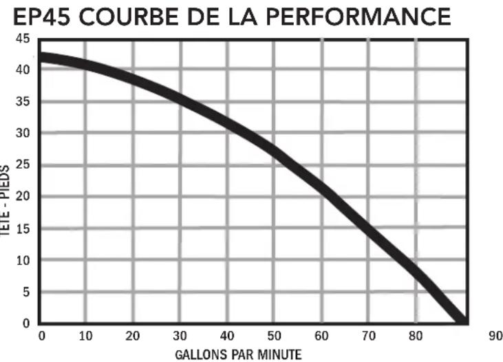
EP45 DIAGRAMME DE LA PERFORMANCE
| Levage total(pieds) | 0 | 5 | 10 | 15 | 20 | 25 | 30 | 40 | 42 |
| GPM | 90 | 83 | 76 | 69 | 61 | 52 | 42 | 12 | 0 |

PUMP
1899 Cottage Street, Ashland, Ohio 44805 Telephone: 855 281-6830 Fax: 877 326-1994 ashlandpump.com
AP-0162/EP40/45 OM-rev07/2020