
TG-98TA/5 - DJ Equipment JTS - Free user manual and instructions
Find the device manual for free TG-98TA/5 JTS in PDF.
User questions about TG-98TA/5 JTS
0 question about this device. Answer the ones you know or ask your own.
Ask a new question about this device
Download the instructions for your DJ Equipment in PDF format for free! Find your manual TG-98TA/5 - JTS and take your electronic device back in hand. On this page are published all the documents necessary for the use of your device. TG-98TA/5 by JTS.
USER MANUAL TG-98TA/5 JTS
natural_image
Two JTS-93A wireless earwatches with digital displays and antenna, shown against a plain light blue background (no text or symbols visible on devices themselves).TG-98RA/5
→ Other spectrum topics: SRD Regulations and indicative list of equipment sub-classes
→ EFIS and National Frequency Tables
2 Wichtige Hinweise
These instructions are intended for users without any specific technical knowledge. Please read the instructions carefully prior to operation and keep them for later reference. An illustration of the unit can be found on page 2.
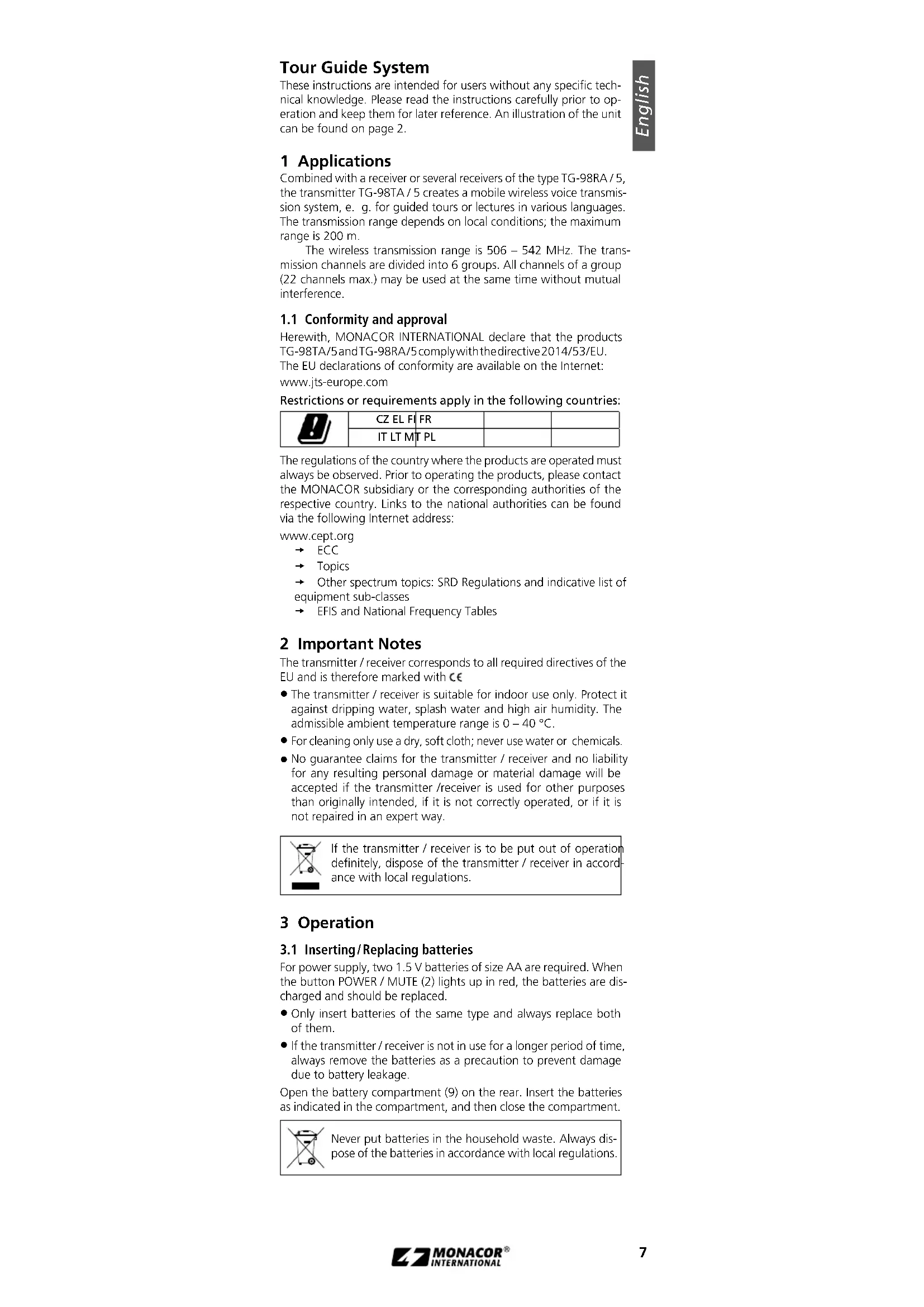
1 Applications
Combined with a receiver or several receivers of the type TG-98RA / 5, the transmitter TG-98TA / 5 creates a mobile wireless voice transmission system, e. g. for guided tours or lectures in various languages. The transmission range depends on local conditions; the maximum range is 200 m.
The wireless transmission range is 506 - 542 MHz. The transmission channels are divided into 6 groups. All channels of a group (22 channels max.) may be used at the same time without mutual interference.
1.1 Conformity and approval
Herewith, MONACOR INTERNATIONAL declare that the products TG-98TA/5 and TG-98RA/5 comply with the directive 2014/53/EU. The EU declarations of conformity are available on the Internet: www.jts-europe.com
Restrictions or requirements apply in the following countries:
 | CZ EL FI FR | ||
| IT LT MT PL |
The regulations of the country where the products are operated must always be observed. Prior to operating the products, please contact the MONACOR subsidiary or the corresponding authorities of the respective country. Links to the national authorities can be found via the following Internet address:
www.cept.org
→ ECC
→ Topics
→ Other spectrum topics: SRD Regulations and indicative list of equipment sub-classes
→ EFIS and National Frequency Tables
2 Important Notes
The transmitter / receiver corresponds to all required directives of the EU and is therefore marked with €€
- The transmitter / receiver is suitable for indoor use only. Protect it against dripping water, splash water and high air humidity. The admissible ambient temperature range is 0 – 40 °C.
- For cleaning only use a dry, soft cloth; never use water or chemicals.
- No guarantee claims for the transmitter / receiver and no liability for any resulting personal damage or material damage will be accepted if the transmitter / receiver is used for other purposes than originally intended, if it is not correctly operated, or if it is not repaired in an expert way.

If the transmitter / receiver is to be put out of operation definitely, dispose of the transmitter / receiver in accordance with local regulations.
3 Operation
3.1 Inserting/Replacing batteries
For power supply, two 1.5 V batteries of size AA are required. When the button POWER / MUTE (2) lights up in red, the batteries are discharged and should be replaced.
- Only insert batteries of the same type and always replace both of them.
- If the transmitter / receiver is not in use for a longer period of time, always remove the batteries as a precaution to prevent damage due to battery leakage.
Open the battery compartment (9) on the rear. Insert the batteries as indicated in the compartment, and then close the compartment.

Never put batteries in the household waste. Always dispose of the batteries in accordance with local regulations.
3.2 Connecting the microphone to the transmitter
The transmitter (black housing marked with a "T") is equipped with an internal microphone (3). Instead of the internal microphone, the clip-on microphone (11) can be used alternatively. Place the pop shield on the microphone. Clamp the microphone cable into the holder (10) as illustrated in fig. 3 and attach the holder to your clothes (e. g. tie), as close to your mouth as possible. Connect the microphone to the jack (4). Thus, the internal microphone is switched off.
3.3 Connecting the earphone to the receiver
The receiver (grey housing marked with an "R") is equipped with an integrated speaker ▶(3). Instead of this speaker, the earphone provided can be used to reproduce sound. Wrap the foam cover around the earphone as a padding: Put the earphone (with the JTS logo to the rear) into the unprinted pocket of the cover. Wrap the cover around the earphone and slip the second pocket over it. The printing ▶will mark the side where sound is emitted. Connect the earphone to the jack (4) and attach the earphone to your ear.
3.4 Wearing options
There are two wearing options for the transmitter / receiver: Attach its clip (8) to your clothes (e. g. belt or trouser pocket) or wear it on the lanyard provided (7):
Pull the thin loop of the lanyard over the clip (fig. 2), shift the stopper to adjust the desired length of the lanyard and put the lanyard around your neck. When the snap buckle is unlocked, the transmitter / receiver can be easily removed or exchanged.
3.5 Switching on / Setting the transmission channel
The table on page 3 shows all available channels. When up to 22 tour guide systems are used at the same time (e.g. for lectures in various languages), select the channels from the same group. There will be no mutual interference with channels of the same group.
1) For the time being, switch on the receiver only: Keep the button POWER (2) pressed until the display (5) lights up.
2) Keep the button SET (6) pressed until ⬤ or ⬤ to select the group.
3) Press the button SET again: The right digit for the channel starts flashing. Use the button or select the channel.
4) Press the button SET again to save the setting. Sisobiefly indicated and the symbol (no reception) appears. If the antenna symbol appears instead, interference signals or signals from another wireless transmission system are received. In this case, use a different channel.
5) Switch on the transmitter and set it to the channel of the receiver.
3.5.1 Display information
| Meaning | Transmitter | Receiver | |
| Y_n/Y_n | transmission power 10 mW/20 mW | × | |
| reception indication | × | ||
| ∅ | automatic switch-off | × | |
| ∅ | microphone muted | × | |
| no reception | × | ||
| ∅ | low battery alarm (beep) | × | |
| ∅∅ | battery full | × | × |
| ∅ | battery discharged | × | × |
| ∅ | key lock | × | × |
| 6-21 | group number – channel number | × | × |
3.6 Adjusting the volume and the microphone sensitivity/Muting the microphone
1) Use the control VOLUME (1) of the receiver to adjust the volume for the speaker or earphone.
Caution: Never adjust the earphone to a very high volume. Permanent high volumes may damage your hearing! The limiter should always be activated (chapter 3.7).
2) Use the control VOLUME of the transmitter to adjust the microphone sensitivity. When the volume is too high and the microphone signal is distorted, reduce the sensitivity. If the volume of the signal is too low, the signal-noise ratio will be poor; in this case, increase the sensitivity accordingly.
3) To mute the microphone during intervals, briefly press the button POWER / MUTE (2) on the transmitter. The symbol is displayed and the display backlight starts flashing after a while. To unmute the microphone, briefly press the button POWER / MUTE again.
3.7 Adjusting the transmission power / Limiting the volume
A small switch can be found on the top left of the battery compartment of the transmitter / receiver (remove the batteries, if necessary).
Use the switch to adjust the transmission power on the transmitter:
H = high power for a high range, but shorter battery life (indication Y_at )
L = low power for a long battery life, but shorter range (indication Y)
The receiver is equipped with a limiter for limiting the volume of the earphone. To activate this limiter, set it to ON; to deactivate it, set it to OFF.
3.8 Automatic switch-off / Low battery alarm
A function is available which will automatically switch off the receiver if the receiver does not receive any signal from the transmitter for 30 minutes.
1) To activate this function, keep the button SET pressed on the receiver until SET is briefly indicated. The left digit for the channel group starts flashing.
2) Press the button SET twice so that is indicated.
3) Use the button Ato activate the function (indication ADEFOn). A clock symbol Gappears; this symbol starts flashing when no signal is received. To deactivate the function, use the button √
4) Press the button SET again to save the setting.
When the batteries are discharged, the button POWER / MUTE
(2) lights up in red and the battery symbol Starts flashing. In addition, a low battery alarm is available: The receiver will emit two short beeps when the batteries are discharged.
1) To activate the alarm feature, keep the button SET pressed on the receiver until SET be refrly indicated. The left digit for the channel group starts flashing.
2) Press the button SET three times so that L is inelicated.
3) Use the button to activate the function (indication L_ab A bell symbol appears. To deactivate the function, use the button
4) Press the button SET again to save the setting.
3.9 Key lock
A key lock feature is provided to protect the transmitter / receiver from inadvertent operation or tampering: Keep the buttons and pressed at the same time until Loc briefly indicated and the symbol appears. When any button is pressed now, the message LocOn will appear.
To deactivate the key lock feature, keep the buttons and pressed until is briefly indicated and the symbol disappears.
3.10 Switching off
To switch off the transmitter / receiver, keep the button POWER pressed until the display indicates OFF.
4 Specifications
Radio frequency range: ..... 506–542 MHz (for channels refer to page 3)
Audio frequency range: ..... 40 Hz – 18 kHz
Transmission power (EIRP): ... L: 10 mW, H: 20 mW
Operating range: 200 m max.
Microphone in the transmitter.. electret microphone
Power supply: 2 (rech.) batteries of size AA
Operating time:.... 10 h approx.
Dimensions (W × H × D): .... 62 × 112 × 28mm
Weight: 72g
Subject to technical modification.
→ ECC
→ Topics
→ Other spectrum topics: SRD Regulations and indicative list of equipment sub-classes
→ EFIS and National Frequency Tables
→ ECC
→ Topics
→ Other spectrum topics: SRD Regulations and indicative list of equipment sub-classes
→ EFIS and National Frequency Tables