RAW370ZWA - Basket ETNA - Free user manual and instructions
Find the device manual for free RAW370ZWA ETNA in PDF.

User questions about RAW370ZWA ETNA
0 question about this device. Answer the ones you know or ask your own.
Ask a new question about this device
Download the instructions for your Basket in PDF format for free! Find your manual RAW370ZWA - ETNA and take your electronic device back in hand. On this page are published all the documents necessary for the use of your device. RAW370ZWA by ETNA.
USER MANUAL RAW370ZWA ETNA
Mounting the cooker hood
Gebruikte pictogrammen - Pictogrammes utilisés Benutzte Piktogramme - Pictograms used
natural_image
Two symbolic icons: a warning triangle with an exclamation mark and a light bulb with rays (no text or labels)natural_image
Simple diagram with four white circles containing symbols: plus, sun, person, and minus on black background (no text or labels)natural_image
Technical line drawing of a mechanical component with a grid-like base and a small rectangular component (no text or symbols)natural_image
Diagram showing a conveyor belt with a small component and warning symbols (no text or labels)Let op!
text_image
Diagram illustrating the process of inserting a solar panel into a device, with arrows indicating the transformation.natural_image
Diagram showing a grid panel inside a device with an arrow indicating rotation or movement, next to a blank rectangular panel (no text or symbols)Belangrijk:
$$ G R O E N / G E E L = A a r d e $$
Let op:
text_image
Prohibition sign with crossed-out trash bin and no text or symbolsnatural_image
Two gray warning symbols: a triangular warning triangle with an exclamation mark and a light bulb with radiating lines (no text or labels)natural_image
Four white circular icons on a black background: plus, sun, person, and minus (no text or symbols)natural_image
Technical line drawing of a mechanical component with a grid-like base and a small rectangular component (no text or symbols)natural_image
Diagram showing a battery cell inside a container with warning symbols (no text or labels)Remarque!
text_image
Diagram illustrating the process of inserting a solar panel into a device, showing step-by-step assembly and final state.natural_image
Diagram showing a solar panel mounted on a rectangular base with an arrow indicating rotation (no text or symbols present)Important :
$$ \text { MARRON } = \text { L (tension) } $$
$$ \mathrm{BLEU} = \mathrm{N(neutre)} $$
$$ \text { V E R T / J A U N E } = \text { t e r r e } $$
Remarque :
text_image
Warning symbol for a trash bin with crossed lines indicating no waste, and a blank sign below.natural_image
Two gray warning symbols: a triangular warning triangle with an exclamation mark and a light bulb with radiating lines (no text or labels)natural_image
Four white circular icons on a dark background: sun, plus sign, person, and minus sign (no text or symbols beyond basic markings)natural_image
Technical line drawing of a rectangular electronic component with a grid-like top and a small rectangular slot, no text or symbols present.natural_image
Diagram of a mechanical component with a grid-like structure and a small rectangular block, enclosed in a circular boundary (no text or symbols)
Hinweis!
flowchart
graph TD
    A["Rectangular Device"] --> B["Square with Circle"]
    style A fill:#f9f,stroke:#333
    style B fill:#bbf,stroke:#333
Geruchsfilter
text_image
Diagram illustrating the process of inserting a solar panel into a device, showing step-by-step assembly and final state.natural_image
Diagram showing a solar panel mounted on a rectangular base with an arrow indicating rotation (no text or symbols present)Wichtig:
text_image
Prohibition sign with crossed-out trash bin and no text or symbolsElectrical connection 10
Mounting the cooker hood 10
Environmental aspects
Disposal of packaging and appliance 11
Installation
Mounting the cooker hood 12
Introduction
natural_image
Two symbolic icons: a warning triangle with an exclamation mark and a light bulb with rays (no text or labels)Reading through these instructions for use will help you quickly find information about all the options you are offered by this appliance. It contains information for your safety and about the maintenance of the appliance.
Read the separate safety instructions before using the appliance!
Keep the instructions for use and the installation instructions. They will be of value to any later user of this appliance.
You can find the most recent version of the instructions for use on our website.
Description
text_image
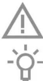
3 3 32 2 22 21 1 1 111- Extraction speeds LED indication
- Grease filter
- Lighting
- Lighting on/off key
- (+) increase extraction power key
- (-) decrease extraction power key
- Extraction on/off key
text_image
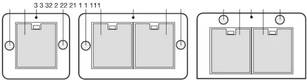
4 + - 6 7 5Operation
Remote control
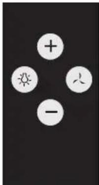
text_image
Image displaying four white circular icons with plus, sun, and minus signs arranged around a central symbol.Switching the fan on and off
- Touch the extraction on/off key.
• The cooker hood switches on at speed 1.
- The indicator on the cooker hood shows the selected speed:
$$ \triangleright \text { green } = \text { speed } 1; $$
$$ \triangleright \text { orange } = \text { speed 2 }; $$
$$ \triangleright r e d = s p e e d 3; $$
red, flashing = speed 4 (maximum of 7 minutes, after which the speed switches back to speed 3).
- If so required, select a higher speed using the '+' key.
- Select a lower speed using the '-' key.
Switching the lighting on and off
- Touch the lighting on/off key.
The light turns on.
▶Touch the on/off key again to switch the lighting off.
Linking the remote control to the cooker hood
- Disconnect the cooker hood from the power supply by setting the group fuse in the meter cupboard to '0' or removing the fuse from the fuse holder. If present, the cooker hood can also be disconnected from the power supply with the On / Off switch located at the top of the cooker hood.
- Reconnect the cooker hood to the mains by setting the group fuse to '1' or placing this in the fuse holder.
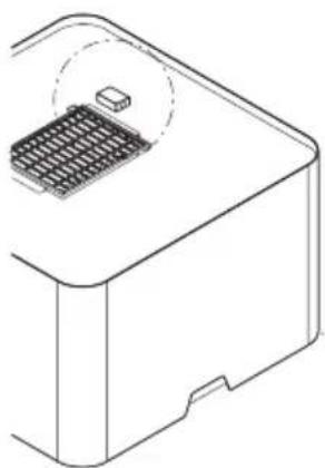
natural_image
Technical line drawing of a mechanical component with a grid-like base and a small rectangular component (no text or symbols)- Within 5 seconds, touch the lighting key until the lighting is on.
- Within 5 seconds, touch the extraction on/off key.
▶Wait at least 10 seconds before you using the cooker hood.
If the remote control is replaced, repeat the steps for linking the remote control. If present, the cooker hood can be connected to the power supply with the On/Off switch located at the top of the cooker hood.
Entering a new code for the cooker hood
When interference prevents the remote control from working properly, a new code can be entered.
-
Touch the remote control's (-) and (+) keys simultaneously for at least 10 seconds.
The LED on the remote control lights. -
Once again, touch the (-) and (+) keys simultaneously within 3 seconds.
The LED on the remote control flashes 3x.
- Work through the steps for linking the remote control.
Replacing the battery
Remove the remote control's cover and replace the battery with a battery of the same type and voltage. The battery is chemical waste and must be disposed of in a responsible manner and in accordance with government regulations.
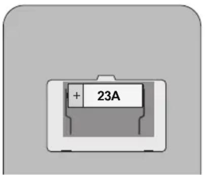
text_image
+ 23ACleaning
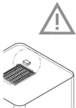
natural_image
Diagram showing a warning sign above a grid device and an exclamation mark (no text or symbols present)
Note!
Before carrying out maintenance work, always disconnect the cooker hood from the power supply by setting the group fuse in the meter cupboard to '0' or removing the fuse. If present, the cooker hood can also be disconnected from the power supply with the On / Off switch located at the top of the cooker hood.
The inside and outside of the cooker hood must be cleaned at regular intervals. Do not use abrasive products. Do not clean with alcohol!
Note!
Failure to follow these instructions for cleaning the appliance and replacing the filters can result in fire. Always follow these instructions! The manufacturer is not liable for damage to the hood or damage caused by fire that is due to inexpert maintenance or the failure to follow the aforementioned recommendations and the safety instructions supplied with the appliance.
Clean the cooker hood with a soft cloth with water and a little detergent. Then wipe with clean water. Do not use corrosive cleaning agents such as soda, and do not use scouring sponges or similar. Treat with a product designed for the maintenance of stainless steel and polish in the direction of the surface finish of the stainless steel.
Metal grease filters
Metal filters must be cleaned once per month (or when the filter cleaning indicator – if present on the model – indicates that this is necessary). Clean the filters with neutral cleaning agents, by hand or in the dishwasher at low temperatures and with a short programme. Put the grease filters in the dishwasher with the openings facing down so that the water can drain. Aluminium grease filters will become dull from the cleaning agents in the dishwasher. This is normal, and does not affect the performance.

The saturation of the filter depends on the intensity of use, the manner of cooking and the regularity with which the grease filters are cleaned.
Grease filters
Clean the grease filter at least once a month. Cleaning will result in the aluminium parts of the filters becoming dull due to the use of cleaning agents, in particular when cleaned in a dishwasher. This is normal, and is not covered by the warranty.
Removing the grease filter
- Switch off the cooker hood.
- Pull the handle of the grease filter towards you and tilt the front downwards.
Important:
Prevent the filter from falling on your hob by supporting it during insertion and removal.
flowchart
graph TD
    A["Rectangular Device"] --> B["Square with Circle"]
    B --> C["Arrow pointing inward"]
    C --> D["Rectangular Device"]
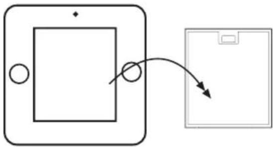
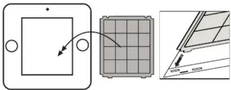
Odor filter
- Remove the grease filter.
- Mount the odor filter.
Important:
The odor filter is clamped between the body and the grease filter. Prevent the filter from falling on your hob by supporting it during insertion and removal.
text_image
Diagram illustrating the process of inserting a solar panel into a device, showing step-by-step assembly and final state.- Fit the grease filter.
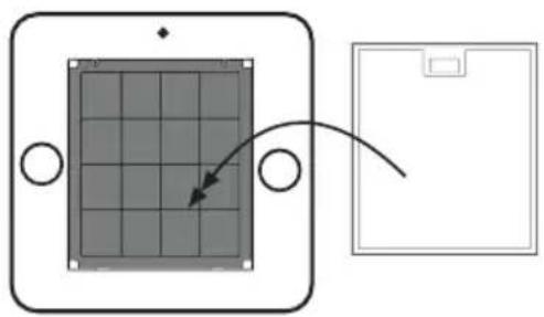
natural_image
Diagram showing a solar panel mounted on a rectangular base with an arrow indicating rotation (no text or symbols)Important:
- The saturation of the filter depends on the intensity of use, the manner of cooking and the regularity with which the grease filters are cleaned.
- The odor filter must be replaced at least once every four months.
- Odor filters cannot be washed for reuse. Saturated carbon is not environmentally friendly, so replace the filter in time.
Long-life filter (made of green plastic)
As a replacement odor filter you can opt for a long-life filter, recognizable by the green plastic. This filter must be cleaned every 4 months.
- The filters can be washed by hand or in the dishwasher at a maximum temperature of 65 °C. The washing cycle must be done without other dishes and without dishwasher detergent. Do not use any cleaning agents!
- Remove excess water. Be careful to avoid damaging the filter. Place the filter in the oven to dry for at least 1 hour at a maximum temperature of 80 °C. After 4 times of use (or if the filtres are damaged), the filters will need to be replaced.
Lighting
This hood is fitted with a light system. This light system has to be replaced by an authorized technician. Do not attempt to replace it by yourself.
The lamp in this household appliance is only suitable for illumination of this appliance. The lamp is not suitable for household room illumination.
General
This appliance must be connected to the mains by a recognized installer who is familiar with and works in accordance with the applicable safety regulations. This appliance meets the requirements of European regulations.
Important information:
- The lowest part of the cooker hood must be at least 65 cm above the cooking surface of the hob.
- Take account of local regulations governing the ventilation of gas appliances.
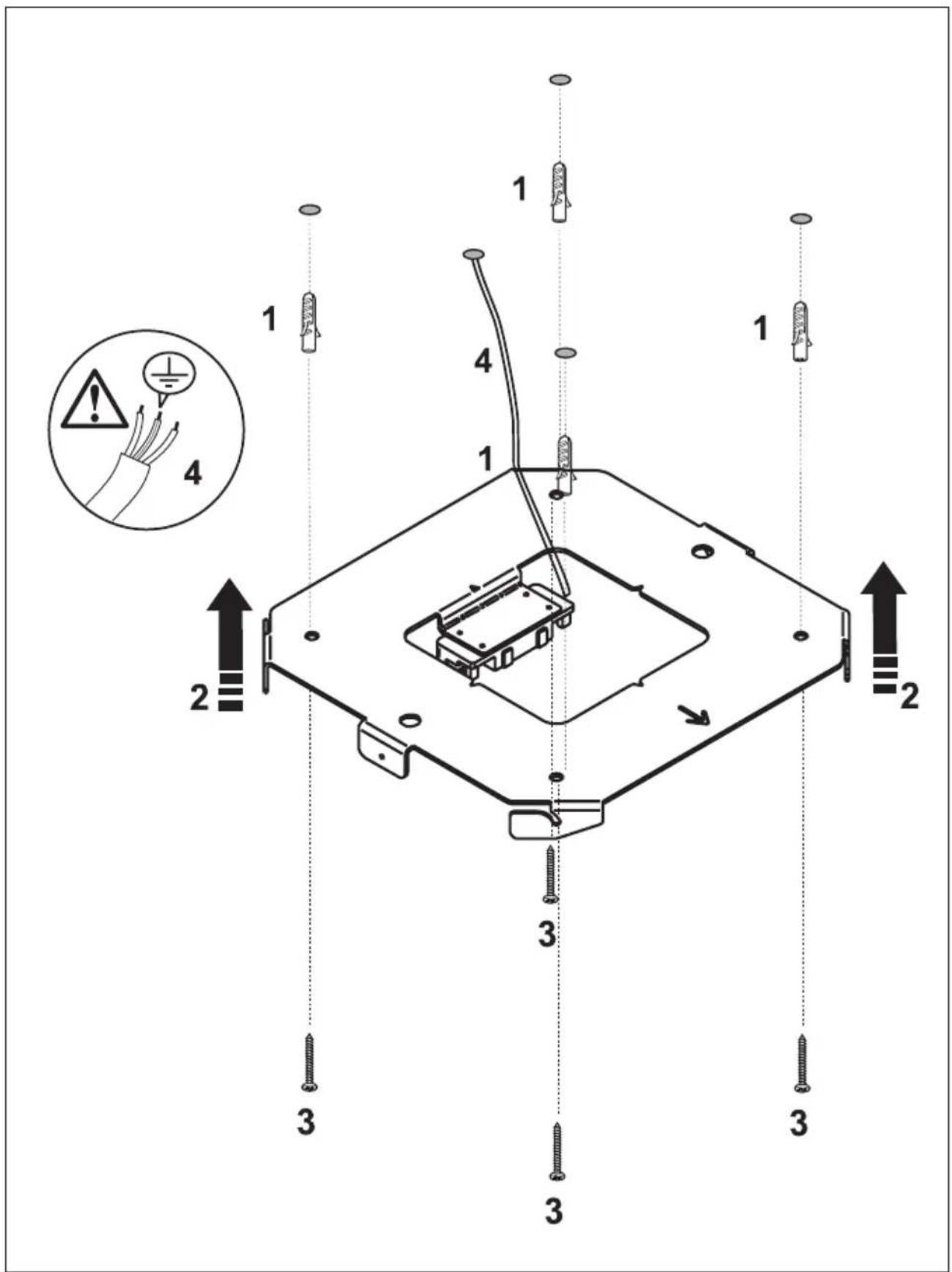
- Before drilling holes, check to make sure that there are no wires in the area.
- The installation material supplied with this cooker hood is suitable for fastening to concrete and reinforced concrete ceilings.
Electrical connection
This appliance must be plugged into an earthed wall socket.
Check to make sure that the voltage specified on the type plate matches the mains voltage. The appliance must be connected to the mains as follows:
$$ B R O W N = L (\text { live }) $$
$$ \text { BLUE } = \text { N (neutral) } $$
$$ \text { GREEN / YELLOW } = \text { Earth } $$
Note:
When you wish to make a fixed connection to the mains, you must make sure that a multipolar switch with a break contact distance of at least 3 mm is fitted in the power cable.
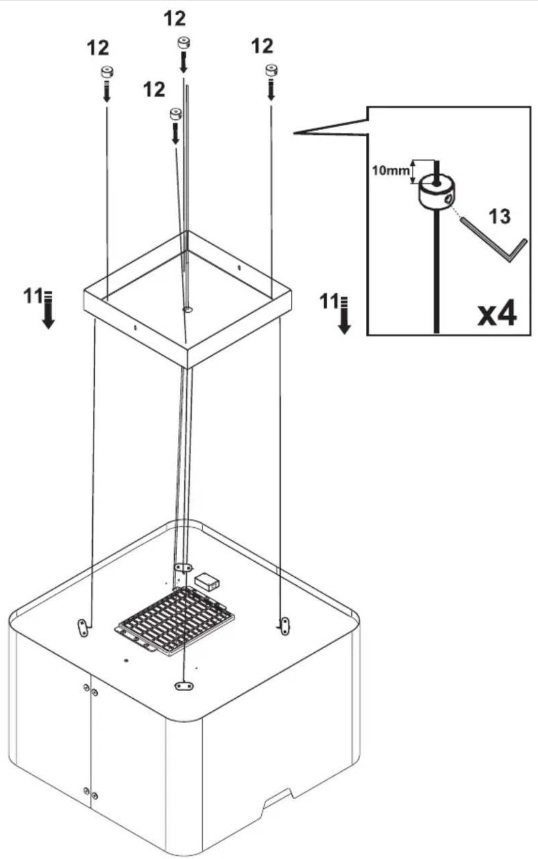
Mounting the cooker hood
The last pages of this manual show the steps for mounting the cooker hood.
Disposal of packaging and appliance
This appliance is made from sustainable materials. This appliance must be disposed of in a responsible manner at the end of its service life. Contact the local authorities for information about the method.
The packaging of the appliance is recyclable. The following materials may have been used:
- cardboard;
• polythene foil (PE); - CFK-free polystyrene (PS-hard foam).
These materials must be disposed of in a responsible manner and in accordance with government regulations.
text_image
Warning symbol for a trash bin with crossed lines indicating no waste, and a black rectangle below.The appliance is marked with a crossed out wheeled bin symbol to draw your attention to the requirement for the separate disposal of domestic electrical appliances. This means that the appliance may not be disposed of in unsorted household waste
at the end of its service life. The appliance must be taken to a special municipal waste processing location for separated waste or to a dealer who provides this service.
Collecting and disposing of domestic appliances separately avoids detrimental consequences for humans and the environment. This ensures that the materials used to make the appliance can be recovered and that substantial savings in the use of energy and raw materials can be achieved.

Declaration of conformity
We hereby declare that our products conform to the applicable European Directives, Regulations and requirements, as well as all requirements in the standards to which reference is made.
RAW370
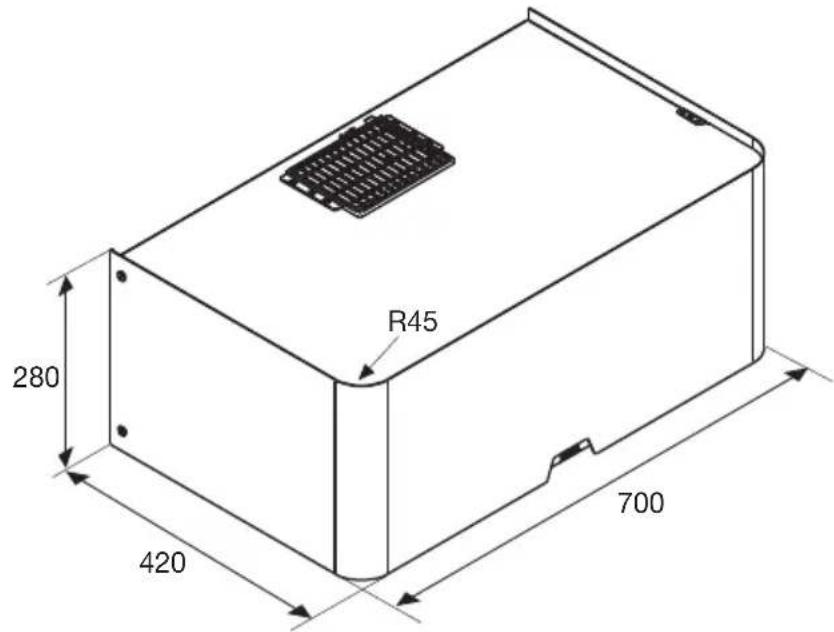
text_image
R45 280 420 700RAW370
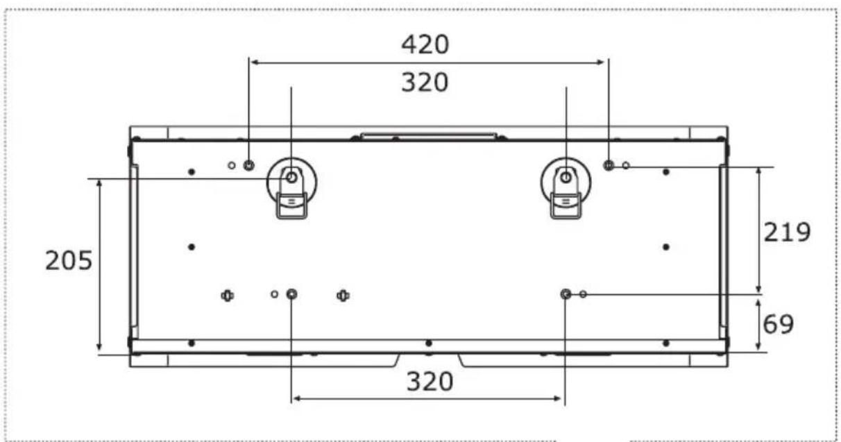
text_image
420 320 205 219 69 320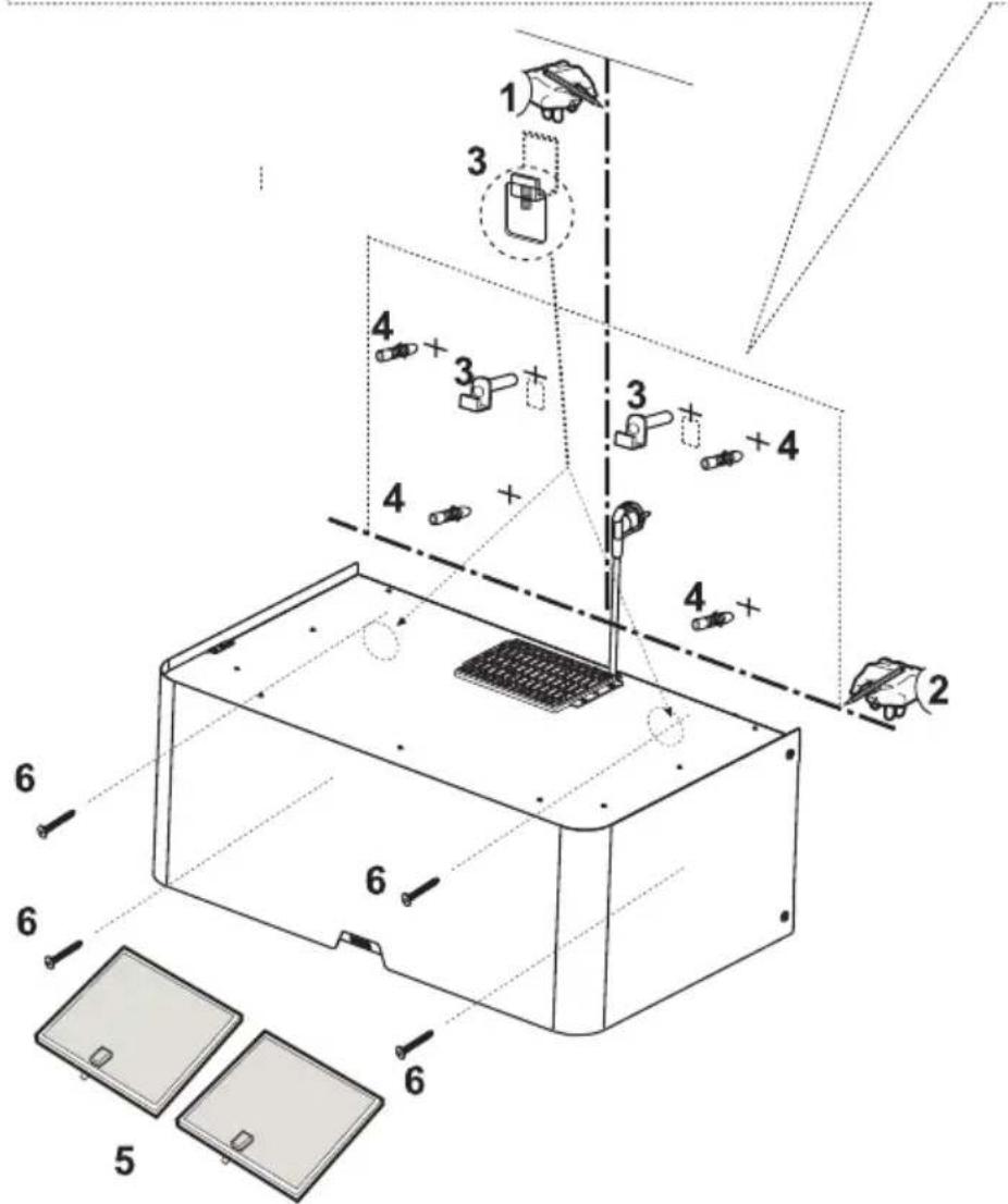
text_image
Technical diagram of a device assembly with numbered components and labeled partsRA345 / RA370
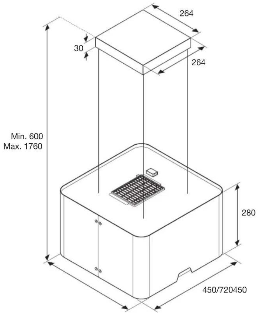
text_image
264 30 264 Min. 600 Max. 1760 280 450/720450RA345 / RA370
1
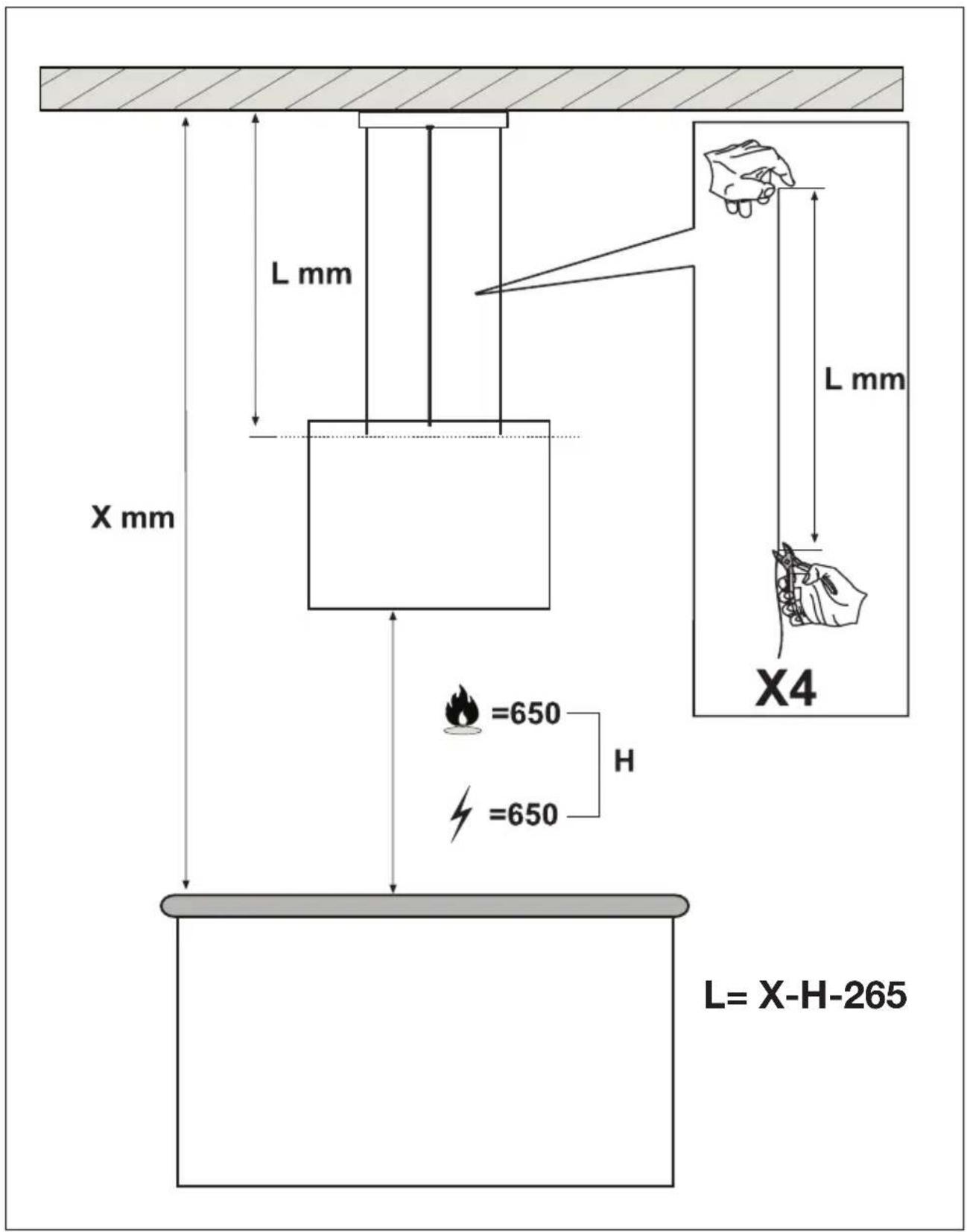
text_image
L mm X mm L mm X4 =650 H =650 L= X-H-265RA345 / RA370
2
text_image
Technical diagram of a device with numbered components and safety warning indicatorsRA345 / RA370
3
text_image
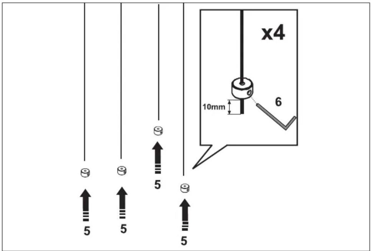
x4 10mm 6 5 5 5 54
text_image
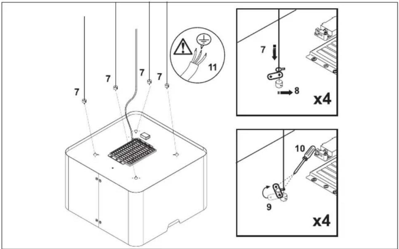
Technical diagram showing electrical wiring and component assembly with numbered parts and safety warning indicatorsRA345 / RA370
5
text_image
12 12 12 12 11 10mm 13 x4 11 12 13RA345 / RA370
6
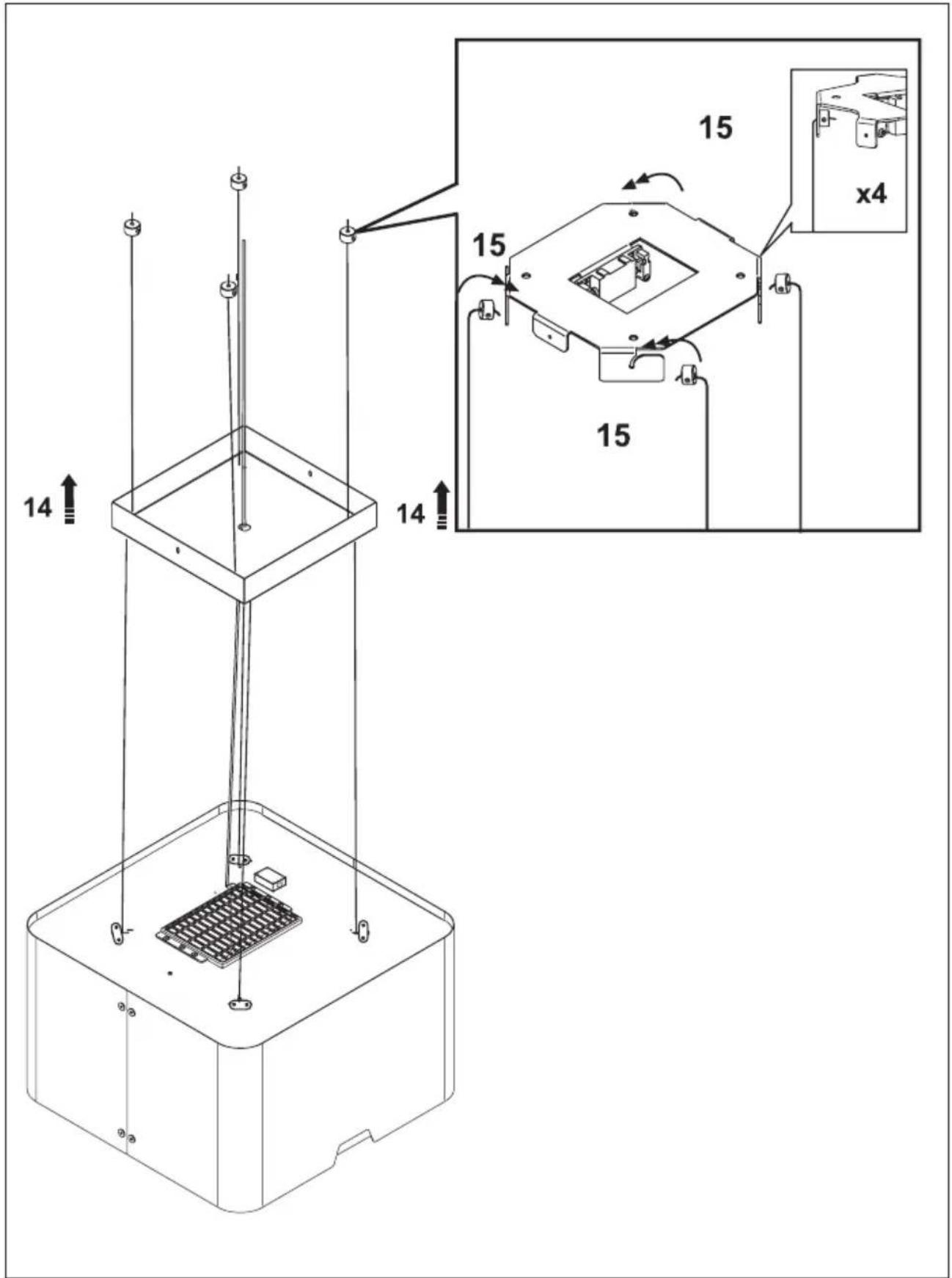
text_image
14 14 15 15 15 x4RA345 / RA370
7
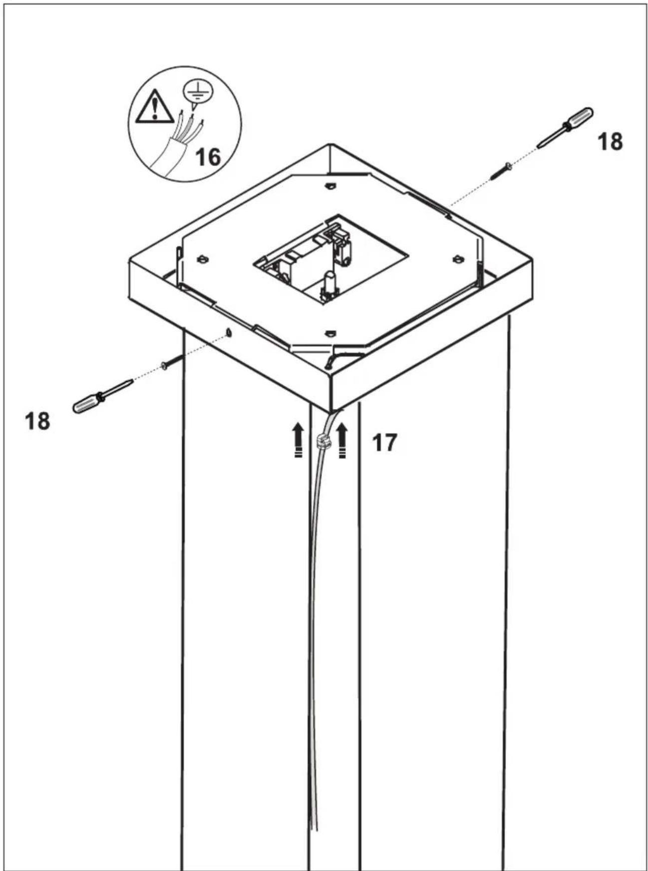
text_image
16 18 17INSTALLATIE - INSTALLATION
The appliance rating label is located on the inside of the appliance.
When contacting the service department, have the complete type number to hand.
Addresses, phone number of the service organisation and the warranty
conditions can be found at www.etna.nl or www.etna.be
www.etna.nl
www.etna.be
789363