
S3B - Vacuum Cleaner NILFISK - Free user manual and instructions
Find the device manual for free S3B NILFISK in PDF.

| Product Type | Professional Vacuum Cleaner |
| Brand | Nilfisk |
| Model | S3B |
| Category | Vacuum for commercial and industrial use |
| Supply Voltage | 230 V (EU version) / 110 V (GB version) |
| Power Consumption | 3 kW |
| Rated Power (EN 60335-2-69) | 2.6 kW (230 V) / 2.2 kW (110 V) |
| Max Vacuum | 2150 mm H₂O |
| Max Airflow (without hose) | 8100 L/min |
| Max Airflow (hose 3 m, ∅ 70 mm) | 7500 L/min |
| Tank Capacity | 50 L or 100 L depending on version |
| Weight (depending on version) | 67 kg (S3B L50) / 70 kg (S3B L100 and LP) |
| Dimensions (L50: L × W × H) | 795 × 600 × 1275 mm |
| Protection Class | IP 43 |
| Sound Pressure Level (Lpf) | 75 dB(A) |
| Vibrations (ah) | ≤ 2.5 m/s² |
| Primary Filter Area | 1.95 m² |
| HEPA Absolute Filter Area | 2.40 m² |
| Absolute Filter Efficiency (MPPS) | 99.995% (H14) |
| Suction Port Diameter | 70 mm |
| Use for Dry Solids | Yes |
| Use for Liquids | Yes, with mechanical liquid stop (float) |
| Emergency Stop | By main switch (position 0) |
| Filtration Options | Primary filter, absolute filter (HEPA H14), dust bag, Longopac® |
| Operating Conditions | Temperature: -10°C to +40°C, humidity ≤ 85%, max altitude 800 m (up to 2000 m with reduced performance) |
| Maintenance and Cleaning | Manual filter shaking, emptying and replacing bags, cleaning filters |
| Spare Parts | Filters, gaskets, motors, carbon brushes, bags (original Nilfisk) |
| Warranty and Compliance | CE declaration of conformity provided; any unauthorized modification voids warranty |
Frequently Asked Questions - S3B NILFISK
User questions about S3B NILFISK
0 question about this device. Answer the ones you know or ask your own.
Ask a new question about this device
Download the instructions for your Vacuum Cleaner in PDF format for free! Find your manual S3B - NILFISK and take your electronic device back in hand. On this page are published all the documents necessary for the use of your device. S3B by NILFISK.
USER MANUAL S3B NILFISK
I Italian
GB English
F French
D Deutsch
E Spanish
natural_image
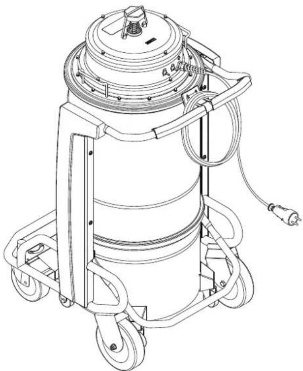
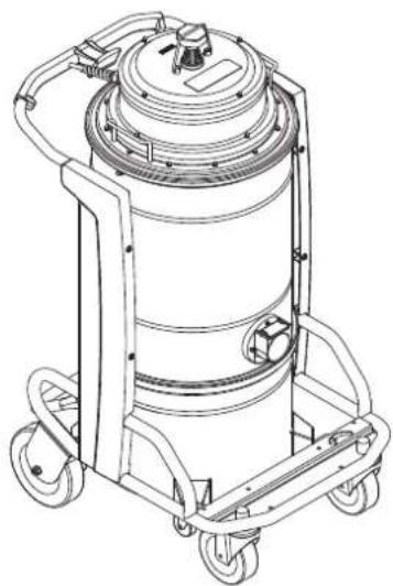
Technical line drawing of a cylindrical industrial vacuum cleaner with attached motors and wiring (no text or symbols)Translation of the original instructions
Table of contents
Instructions for use....2
Operator's safety 2
General information for using the machine 2
Proper uses 2
Improper Use....2
Versions and variations....3
General recommendations....3
Residual Risks....3
EC Declaration of conformity....4
Description of the machine ....5
Machine Parts and Labels 5
Optional kits....5
Accessories 5
Packing and unpacking 5
Unpacking, moving, use and storage 5
Setting to work - connection to the power supply 6
Extensions....6
Dry applications....6
Vacuuming of liquids 6
Technical data 8
Dimensions....8
Controls and indicators....9
Inspections prior to starting 9
Starting and stopping 9
Emergency stopping....9
Operation....9
At the end of a cleaning session 9
Maintenance, cleaning and decontamination....10
Primary filter cleaning with manual system 10
Emptying the container....11
Emptying of the liquid container 11
Dust Bag....11
Longopac® bag for dust collection....11
Replacement of dust bags....11
Main and absolute filter disassembly and replacement.... 12
Installation, cleaning and replacement of the separator (optional).... 12
Tightness inspection.... 13
Disposal....13
Wiring diagrams 13
Recommended spare parts ....14
Troubleshooting....15
Instructions for use
Read the operating instructions and comply with the important safety recommendations identified by the word CAUTION!
Operator's safety

CAUTION!


Before starting the machine, it is absolutely essential to read these operating instructions and to keep them on hand for consultation.
The machine can only be used by people who are familiar with the way it works and who have been explicitly authorised and trained for the purpose.
Before using the machine, the operators must be informed, instructed and trained on how to work it and for which substances its usage is permitted including the safe method for removing and disposing of the vacuumed material.

CAUTION!

The use of the machine by people (including children) with limited physical and mental capacities or lacking in experience and knowledge is strictly forbidden, unless they are supervised by a person who is experienced in the use and safe handling of the machine.
Children must be supervised to make sure they will not play with the machine.

CAUTION!

Before using the machine, always check that any hazardous condition has been eliminated and inform the people in charge about any operational fault.
Check that all guards and protections are correctly mounted and that all safety devices are installed and efficient.
Repairs must only be carried out when the machine is at a standstill and disconnected from the electricity and air supply mains. Never ever carry out repairs without having first received the necessary authorization.

CAUTION!

Any changes made by the user without the Manufacturer's explicit authorization shall invalidate the warranty and hold the Manufacturer harmless from any and all liabilities for damages caused by faulty products.
General information for using the machine
Use the machine in accordance with the laws in force in the country where it is used.
Besides the operating instructions and the laws in force in the country where the device is used, the technical regulations for ensuring safe and correct operation must also be observed (Legislation concerning environmental and labour safety, i.e. European Union Directive 89/391/EC and successive Directives).
Do not perform any operation that could jeopardize the safety of people, property and the environment.
Comply with the safety indications and prescriptions in this instruction manual.
Proper uses
This machine is suitable for commercial use, in hotels, schools, hospitals, factories, shops, offices and apartment hotels for example, for hire and in any case for purposes other than normal domestic use.
This machine is suitable for cleaning and vacuuming solid materials in indoor and outdoor environments.
The machine has been designed to be used by one operator at a time.
This machine consists of a vacuum unit, with an upstream filter unit and a container for collecting the vacuumed material.
Improper Use

CAUTION!

The following use of the device is strictly forbidden:
■ Outdoors in case of atmospheric precipitation.
■ When not placed on horizontal level ground.
■ When the filter unit is not installed.
■ When the vacuum inlet and/or hose are turned to face parts of the human body.
■ Use without the cover on the vacuum unit.
■ When the dust container is not installed.
■ Use without the guards, protective covers and safety systems installed by the manufacturer.
■ When the cooling vents are partially or totally clogged.
■ When the machine is covered with plastic or fabric sheets.
■ Use with the air outlet partially or totally closed.
CAUTION!
The following use of the device is strictly forbidden:
■ When used in narrow areas where there is no fresh air.
■ When the cable or plug is damaged. If appliance is not working as it should, has been dropped, damaged, left outdoors or dropped into water, return it to an authorized service center.
■ Vacuuming liquids with machine not equipped with specific original stopping systems.
■ Do not pull or carry by the cord, use the power cord as a handle, do not close a door on cord, or pull cord around sharp edges or corners. Do not run the appliance over the cord. Keep cord away from heated surfaces.
■ Vacuuming the following materials:
- Burning materials (embers, hot ashes, lit cigarettes, etc.).
- Naked flames.
- Combustible gas.
- Flammable liquids, aggressive fuels (gasoline, solvents, acids, alkaline solutions, etc.).
- Explosive dust/substances and/or ones liable to ignite in a spontaneous way (such as magnesium or aluminium dusts, etc.).
Note: Fraudulent use is not admitted.
Versions and variations
HEPA variants
This machine can be equipped with an upstream filter (HEPA). The procedures for servicing and emptying the machine including removing the dust container, must only be performed by authorized personnel wearing protective clothing. Do not use without the complete filter system in place.
General recommendations
CAUTION!
If an emergency situation occurs:
■ Accident
■ Breakdown
■ Filter breakage
■ Fire outbreak
■ etc.
Disconnect the machine from the power supply and ask for assistance from qualified personnel.
In case the user comes into contact with the vacuumed product, check the cautions shown on the safety technical sheet of the product, which must be made available from the employer.
[ NOTE ]
Check the place of work and substances tolerated for the machine suitable for liquids.
CAUTION!
The machines must not be used or stored outdoors, or in damp places.
Only versions with the level sensor can be used for liquids, if not, they can only be used to vacuum dry materials.
CAUTION!
Version for liquids.
If foam or liquid leaks out of the machine, turn it off immediately and contact qualified personnel for assistance.
[ NOTE ]
These devices must not be used in corrosive environment.
Residual Risks
After carefully considering the risks that are present in all machine operating phases, necessary measures were adopted in order to eliminate the risks for the operators, as far as possible, and/or limit or reduce the risks deriving from hazards that cannot be completely eliminated at the source.
During operations and/or maintenance, operators are exposed to certain residual risks which, due to the nature of the operations themselves, cannot be completely eliminated. Therefore the installer is responsible for providing additional information and/or hazard signals based on the location of machine installation and the material that is handled.
■ Risks due to electrical hazards during maintenance
DANGER
Risk of electrocution if accessing the electrical equipment during maintenance without having deactivated the electrical power supply.
FORBIDDEN
It is forbidden to work on the electric equipment before disconnecting the machine or its parts from the electrical line.
MANDATORY
Have the electrical maintenance operations performed by qualified personnel. Perform the checks on the electric equipment as specified in the manual.
■ Risks to the presence of residual high temperature after stopping the vacuum unit.
During maintenance and cleaning operations, the operator may come into contact while the machine is stopped, with parts of the vacuum unit with surfaces at high temperatures.
Specific warning signs placed in strategic points indicate the hazard due to the presence of hot surfaces and the obligation for the user to wear personal protective equipment, in particular protective gloves.
The potentially hot parts (high temperatures) are identified as follows:

IT IS MANDATORY TO WEAR GLOVES

EC Declaration of conformity
Every machine comes with a EC Declaration of conformity. See fac-simile in fig. 17.
[ NOTE ]
The Declaration of conformity is an important document and should be kept in a safe place to be presented to the Authorities on request.
Description of the machine
Machine Parts and Labels
Figure 1
- Identification plate: Model code, serial number, EC marking, year of manufacture, weight (kg)
- Dust container
- Dust container release lever
- Vacuum inlet
- Air outlet
- Warning plate the operator's attention to the fact that the filter must be shaken only when the machine is off (see par. "Shaking the primary filter" as well).
- Plug for connecting the vacuum cleaner to an electrical socket.
This machine creates a strong air flow which is drawn in through the vacuum inlet and blows out through the outlet.
Before turning on the machine, fit the vacuum hose into the inlet and then fit the required tool on to the end part (refer to the manufacturer's accessory catalogue or Service Centre).
The diameters of the authorized hoses are indicated in the Technical data table.
The machine is equipped with a primary filter which enables it to be used for the majority of applications.
In addition to the primary filter that retains the most common dust, a secondary filter (absolute filter) can be installed.
This machine is equipped with an internal baffle plate which subjects the vacuumed substances to a circular centrifugal movement that makes them drop into the container.
Optional kits
Various optional kits are available for converting the machine.
On request, the machine can be supplied with optional kits already installed. However, they can also be installed at a later date.
Please contact the sales network for further details.
Instructions describing how to fit the optional kits and the relative operation and maintenance manuals are supplied together with the optional kits.
Use only supplied and authorised genuine spare parts.
Accessories
Various accessories are available; refer to the manufacturer's accessory catalogue.
Use only genuine accessories supplied and authorised by the manufacturer.
Packing and unpacking
All the dispatched equipment has been thoroughly checked before being delivered to the haulage contractor.
On arrival, check the machine to see that it has not been damaged during transport. In case of damage, immediately lodge a complaint with the haulage contractor.
Dispose of the packing materials in compliance with the laws in force.
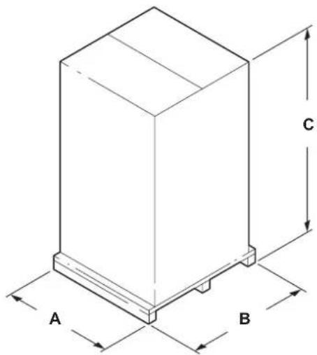
Draws
Figure 2
| Model A (mm) | B (mm) C | (mm) kg (*) | ||
| S3B 50L | 700 | 860 | 1,350 | 80 |
| S3B 100L | 700 | 860 | 1,750 | 86 |
| S3B LP | 700 | 860 | 1,750 | 89 |
(*) Weight with packing
Unpacking, moving, use and storage
To unpack the vacuum unit, remove the retainers with a hammer and a screwdriver.
Also remove the fastening devices placed by the manufacturer when packing, by using suitable tools.
Release the wheel brakes and remove the machine from the supporting platform, by using a ramp that can provide adequate capacity, and by driving the vacuum cleaner by the handle.
Operate on flat, horizontal surfaces.
The load-bearing capacity of the surface the machine is placed on must be suitable for bearing its weight.
If the device is to work in a fixed position, allow wide space around the device in order to ensure freedom of the movement and allow the maintenance staff to operate with ease.

The manufacturer shall not be liable for any damages caused to the machine during lifting, when the lifting equipment supplied by the manufacturer is not used.

When several supporting platforms are provided, the supporting platform to which the machine is anchored must be handled with a forklift truck that can provide adequate capacity. Then unpack the machine by laying it down on a flat and horizontal surface that can provide adequate capacity for the vacuum cleaner weight.
Setting to work - connection to the power supply

CAUTION!

■ Make sure there is no evident sign of damage to the machine before starting work.
■ Before plugging the machine into the electrical mains, make sure the voltage rating indicated on the data plate corresponds to that of the electrical mains.
■ Connect the plug into a socket with a correctly installed ground contact/connection. Make sure that the machine is turned off.
■ The plugs and connectors of the connection cables must be protected against splashes of water.
■ Check that for proper connection to the electrical mains.
■ Use the machine only when the cables that connect to the electricity mains are in perfect condition (damaged cables could lead to electric shocks!).
■ Regularly check there are no signs of damage, excessive wear, cracks or ageing on the electric cable.

CAUTION!

When the device is operating, do not:
■ Crush, pull, damage or tread on the cable that connects to the electrical mains.
■ Only disconnect the cable from the electrical mains by removing the plug (do not pull the cable).
■ Only replace the electric power cable with one of the same type as the original: H07 RN-F, The same rule applies if an extension is used.
- The cable must be replaced by the manufacturer's Service Centre staff or by equivalent qualified personnel.
The system safety officers must:
■ Prevent any improper use or manoeuvre.
■ Make sure that the safety devices are not removed or tampered with.
■ Check that all maintenance operations are regularly performed;
■ Make sure that no machine part (couplings, holes, etc.) is modified to attach additional devices;
■ Make sure that only original Nilfisk spare parts are used.
NOTE
The user shall be responsible for ensuring that installation complies with the all relevant local provisions. The equipment must be installed by qualified technicians who have read and understood the instructions herein.
Extensions
If an extension cable is used, make sure it is suitable for the power input and protection degree of the machine.
| Max power (kW) 3 5 15 22 | ||||
| Minimum section (mm2) | 2.5 | 4 10 16 | ||
| Maximum length (m) | 20 | |||
| Cable | H07 RN - F | |||

CAUTION!

Sockets, plugs, cable clamps, connectors and installation of the extension cable must maintain the IP protection degree of the machine, as indicated on the data plate.

CAUTION!

The machine power socket must be protected by a differential circuit-breaker with surge current limitation, that shuts off the power supply when the current discharged to the ground exceeds 30 mA for 30 msec. or an equivalent protection circuit.

CAUTION!

Never spray water on the machine: this could be dangerous for people and could short circuit the power supply.
Dry applications
[ NOTE ]
The supplied filters and the bag (if applicable) must be installed correctly.
![NILFISK S3B - [ NOTE ] - 1](/content/2026/04/639956/images/1c8e12fd62ca154f52b52255723c675fbd4968e13f47d02fdcfdb4484a6a8cab.jpg)
CAUTION!

Comply with the safety regulations governing the vacuumed materials.
Vacuuming of liquids

CAUTION!

Comply with the safety regulations governing the vacuumed materials.

CAUTION!

■ Make sure the liquid stop device is working correctly before vacuuming liquids.
■ In case of foam, immediately stop working, turn off the machine and empty the container.
■ Regularly clean the liquid level limiting device and check to make sure that there are no signs of damage.
■ Dirty liquid vacuumed by the machine must be considered conductive.
CAUTION!
Do not use the machine if the liquid mechanical stop is not installed!
If it's used without the float, the machine may be seriously damaged.
CAUTION!
When vacuuming a mix of water and air, take care to avoid overloading the motor of the vacuum unit.
The machine vacuums liquids and deposits them into the container.
When the machine vacuums liquids it must be equipped with liquid mechanical stop.
The liquid mechanical stop requires a special container with relevant nozzle.
Before starting the machine, close the inlet on the filtering chamber with the relevant plug and fit the vacuum hose in the inlet on the dust container, then fit the required tool on to the end part of the hose (refer to the manufacturer's accessory catalogue or Service Centre).
The liquid mechanical stop stops the vacuuming operation (the vacuuming units remain activated) when the liquid container is full; it is then necessary to turn off the machine and empty the liquid container.
The machine does not switch off automatically.
Technical data
| Parameter | Units of measurement | S3B | |||
| EU UK | |||||
| Voltage V 230 110 230 | |||||
| Power rating kW 3 | |||||
| Power rating (EN 60335-2-69) kW 2.6 2.2 2.6 | |||||
| Max vacuum mm H20 2150 1680 | 215 | ||||
| Maximum air flow rate without hose and reductions | L/m' | 8100 | 7080 | 8100 | |
| Maximum air flow rate (3 m ∅ 70 mm hose) | L/m' | 7500 | 6550 | 7500 | |
| Sound pressure level (Lpf) (EN60335-2-69) (*) | dB(A) | 75 | |||
| Vibration, ah (**) | m/s2 | ≤2.5 | |||
| Protection | IP 43 | ||||
| Insulation | Class | GB | |||
| Container capacity | L | 50/100 | |||
| Longopac® dust bag capacity L | - | ||||
| Vacuum inlet (diameter) | mm | 70 | |||
| Allowed hoses | mm | 70 | |||
| Primary filter surface | m2 | 1.95 | |||
| Upstream absolute H filter surface | m2 | 2.40 | |||
| Absolute filter efficiency according to MPPS method (EN 1822) | % | 99.995 (H14) | 99.995 (H14) | 99.995 (H14) | 99.995 (H14) |
| Weight | kg | 70 | |||
(*) Measurement uncertainty KpA < 1.5 dB (A). Noise emission values obtained according to EN-60335-2-69
(**) Total value of vibration output to the operator arm and hand
Dimensions
Figure 3
| Model | S3B L50 | S3B L100 | S3B LP |
| A (mm) | 795 | 795 | 795 |
| B (mm) | 600 | 600 | 600 |
| C (mm) | 1,275 | 1,580 | 1570 |
| Weight (kg) | 67 | 70 | 70 |
[ NOTE ]
■ Storage conditions:
Temperature: -10^ ÷ +40^
Humidity: ≤ 85%
■ Operating conditions:
Maximum altitude: 800 m
(Up to 2,000 m with reduced performances)
Temperature: -10^ ÷ +40^
Humidity: ≤ 85%
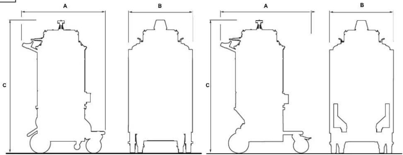
Controls and indicators
Figure 4
1. Start/stop switch
2-way selector:
position "0" - The vacuum cleaner is turned OFF.
position "I" - The vacuum cleaner is turned ON.
2. Power indicator
Indicates the vacuum cleaner is powered.
3. Manual filter shaker knob
Inspections prior to starting
Figure 5
1. Vacuum inlet
Before starting, check that:
■ The filters are installed.
■ The closing band is properly tightened.
■ The vacuum hose and tools have been correctly fitted into the vacuum inlet (1).
■ In case of liquid application, the liquid mechanical stop is properly installed inside the liquid container:
■ The bag or safety container is installed, if applicable.
Do not use the device if the filters are faulty.
Starting and stopping
Figure 4
Before starting the machine, lock the castor brakes
■ Turn switch (1) to position "I" to start the vacuum cleaner.
■ Turn the switch to position "0" to stop the vacuum cleaner.
Emergency stopping
Figure 4
Turn the switch to position "0" to stop the vacuum cleaner.
The motors and internal components of the vacuum cleaner will still be electrically powered.
Operation
The air speed in the vacuum hose must not be less than 20 m/s.
All machines can be used only with hoses whose diameters comply with the specifications in the "Technical Data" table.

Consult the "Troubleshooting" chapter if faults occur.
At the end of a cleaning session
■ Turn off the machine and remove the plug from the socket.
■ Wind up the connection cable.
■ Empty the container and clean the machine as described in the “Maintenance, cleaning and decontamination” paragraph.
■ Wash the container with clean water if aggressive substances have been vacuumed.
■ Store the machine in a dry place, out of reach of unauthorised people.
■ Lock the castor brakes.
■ During transport and when not using the machine, close the vacuum inlet with the relevant plug (if equipped).
Maintenance, cleaning and decontamination
CAUTION!
Disconnect the machine from its power source before cleaning, servicing, replacing parts or converting it to obtain another version/variant.
- Carry out only the maintenance operations described in this manual.
■ Use only original spare parts.
■ Do not modify the machine in any way.
Failure to comply with these instructions could jeopardize your safety. Moreover, such action would immediately void the EC declaration of conformity/ incorporation issued with the machine.
CAUTION!
For maintenance procedures not described in this manual, please contact the manufacturer's technical support or sales network.
CAUTION!
To guarantee the safety level of the machine, only original spare parts supplied by the manufacturer should be used.
CAUTION!
The precautions described below must be taken during all maintenance operations, including cleaning and replacing the primary and absolute filters.
CAUTION!
This Class H machine can collect dust hazardous for the health. The procedures for servicing and emptying the machine including removing the dust bag, must only be performed by specialised personnel wearing protective clothing. Do not use without the complete filter system in place.
CAUTION!
In particular, on Class H machines, the filtering efficiency of the machine must be checked at least once a year, or more often if required by national legislation. The test method for checking the filtering efficiency of the machine is indicated in standard EN 60335-2-69, par. 22.AA.201.2. If the test isn't passed, it must be repeated after the class H filter has been changed.
■ To allow the user to carry out the maintenance operations, the machine must be disassembled, cleaned and overhauled as far as is reasonably possible, without causing hazards for the maintenance staff or other people. The suitable precautions include decontamination before disassembling the machine, adequate filtered ventilation of the exhaust air from the room in which it is disassembled, cleaning of the maintenance area, and suitable personal protection.
■ The external parts of the machine must be decontaminated by cleaning and vacuuming methods, dedusted or treated with sealant before being taken out of a hazardous zone.
■ All parts of the machine must be considered as contaminated when they are removed from the hazardous zone and appropriate actions must be taken to prevent dust from dispersing.
■ When maintenance or repair procedure are carried out, all the contaminated elements that cannot be properly cleaned, must be eliminated.
■ These elements must be disposed of in sealed bags in accordance with applicable regulations and local laws on the disposal of such material.
■ This procedure must also be followed for filter disposal (primary and absolute filters).
■ Compartments that are not dust-tight must be opened with suitable tools (screwdrivers, wrenches, etc.) and thoroughly cleaned.
■ A check must be carried out by the manufacturer or the personnel of the same at least once a year. For example: Check the air filters to find out whether the air-tightness of the machine has been impaired in any way and make sure that the electric control panel operates correctly.
Primary filter cleaning with manual system
Figure 4
In relation to the quantity of vacuumed material, turn the vacuum cleaner off and use the knob (3) of the manual filter shaker.
CAUTION!
Stop the machine before using the filter shaker. Do not shake the filter with the machine functioning, as this could damage the filter.
Wait before restarting the machine, to allow the dust to settle.
[ NOTE ]
If the indicator is still in the red area. The vacuum hose or one of the accessories may be clogged, and not the filter. Clean these parts if this is the case.
Emptying the container
CAUTION!
Before proceeding with these operations, turn off the machine and remove the plug from the power socket. Check the machine filtration class.
Before emptying the container it is advisable to clean the filter (see "Cleaning the primary filter" paragraph).
Figure 6
■ Release the dust container with lever, then remove and empty it.
- Clean the machine as described in the “Maintenance, cleaning and decontamination” paragraph.
■ Wash the container with clean water if aggressive substances have been vacuumed.
■ Make sure the gasket is in perfect condition and correctly positioned.
■ Place the container back in position and secure it again.
[ NOTE ]
After the cleaning session, leave the machine running for at least 60 seconds before turning it off. Avoid switching on/off too frequently.
Emptying of the liquid container
CAUTION!
Before proceeding with these operations, turn off the machine and remove the plug from the power socket. Check the machine filtration class.
Before emptying the container it is advisable to clean the filter (see "Cleaning the primary filter" paragraph).
Figure 6
■ Release the container with the lever and remove it, then remove the liquid stop device and empty it.
■ Clean the machine as described in the “Maintenance, cleaning and decontamination” paragraph.
■ Wash the container with clean water if aggressive substances have been vacuumed.
■ Make sure the gasket is in perfect condition and correctly positioned.
■ Place the container back in position and secure it again.
[ NOTE ]
After the cleaning session, leave the machine running for at least 60 seconds before turning it off. Avoid switching on/off too frequently.
[ NOTE ]
The filter element will be wet after liquids have been vacuumed.
A wet filter element can quickly become clogged if the machine is then used to vacuum dry substances.
For this reason, make sure that the filter element is dry or replace it with another one before using the machine for dry materials.
Dust Bag
Figure 7
The machine can be equipped with dust collection bag. In this case, the machine must be equipped with optional accessories (depressor and grid).
If the bag is not installed or is installed improperly, it could create health risks for people exposed.
Longopac® bag for dust collection
Figure 8
The machine can be equipped with dust collection bag. In this case, the material is discharged by gravity when the vacuuming stops. The Longopac® bag can be cut, sealed or closed to the size required.
If the bag is not properly installed, it could create health risks for people exposed.
Replacement of dust bags
CAUTION!
Before proceeding with these operations, turn off the machine and remove the plug from the power socket.
CAUTION!
■ These operations can only be carried out by trained and qualified personnel who must wear adequate clothing, in compliance with the laws in force.
■ Take care not to raise dust during this operation. Wear a P3 protective mask.
In case of hazardous and/or harmful dust, use only the bags recommended by the manufacturer (see "Recommended spare parts").
■ The bag must only be disposed of by qualified personnel and in compliance with the laws in force.
CAUTION!
Use only original Nilfisk bags.
CAUTION!
Only use bags suitable for the machine class you are using.
CAUTION!
Take care not to raise dust during this operation. Wear a P3 mask and other protective clothing plus protective gloves (DPI) suited to the hazardous nature of the dust collected, refer to the laws in force.
How to replace the Dust Bag
Figure 7
■ Close the inlet by using the relevant cap (if equipped).
■ Release the dust container.
■ Remove the dust bag and close it with a clamp, if necessary.
■ Place a new bag, taking care to wrap it around the outer wall of the dust container.
■ Set the dust container into the machine again.
How to replace the Longopac®
Figure 8
■ Turn the bag full of dust on itself to obtain a section of coiled bags to be tightened with two clamps.
■ Place the two clamps at a distance of 50 mm between them, then with a pair of scissors cut between the two clamps.
■ Remove the bag full of dust and place the new section of Longopac®.
Main and absolute filter disassembly and replacement

CAUTION!

When the machine is used to vacuum hazardous substances, the filters become contaminated, therefore:
■ Work with care and avoid spilling the vacuumed dust and/or material;
■ place the disassembled and/or replaced filter in a sealed plastic bag;
■ close the bag hermetically;
■ dispose of the filter in accordance with the laws in force.

CAUTION!

Filter replacement is a serious matter. The filter must be replaced with one of identical characteristics, filtering surface and category.
Otherwise the machine will not operate correctly. Before proceeding with these operations, turn off the machine and remove the plug from the power socket.

CAUTION!

Before performing these operations, clean the filter as described in the “Maintenance, cleaning and decontamination” paragraph.

CAUTION!

Take care not to raise dust during this operation. Wear a P3 mask and other protective clothing plus protective gloves (DPI) suited to the hazardous nature of the dust collected, refer to the laws in force.

CAUTION!

Reassemble with care to avoid trapping your hands between the vacuum unit and the container. Use gloves that provide protection against mechanical risks (EN 388) with a level of protection CAT. II.

CAUTION!

Do not use the Class H filter again after having removed it from the machine.
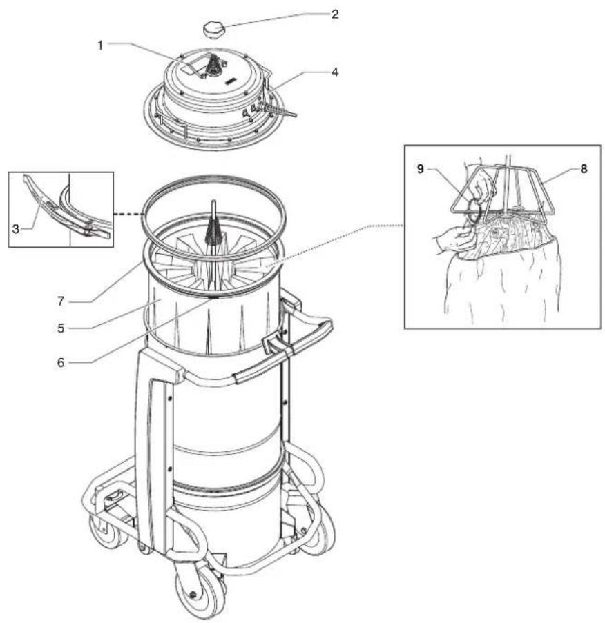
Primary filter replacement, for machines equipped with manual cleaning system
Figure 9
■ Release the stop (1), unscrew the filter shaker knob (2).
■ Release the closing band (3).
■ Lift the motor head (4).
■ Lift filter (5) and unscrew the filter clamp (6) on bearing ring (7).
■ Unscrew cage (8) and overturn the filter, exposing coupling clamp (9).
■ Release the clamps and detach the cage from the filter.
■ Dispose of the filter according to the laws in force.
■ Fit the new filter and secure it in the cage with special clamps. Assemble the components in the reverse order of disassembly.
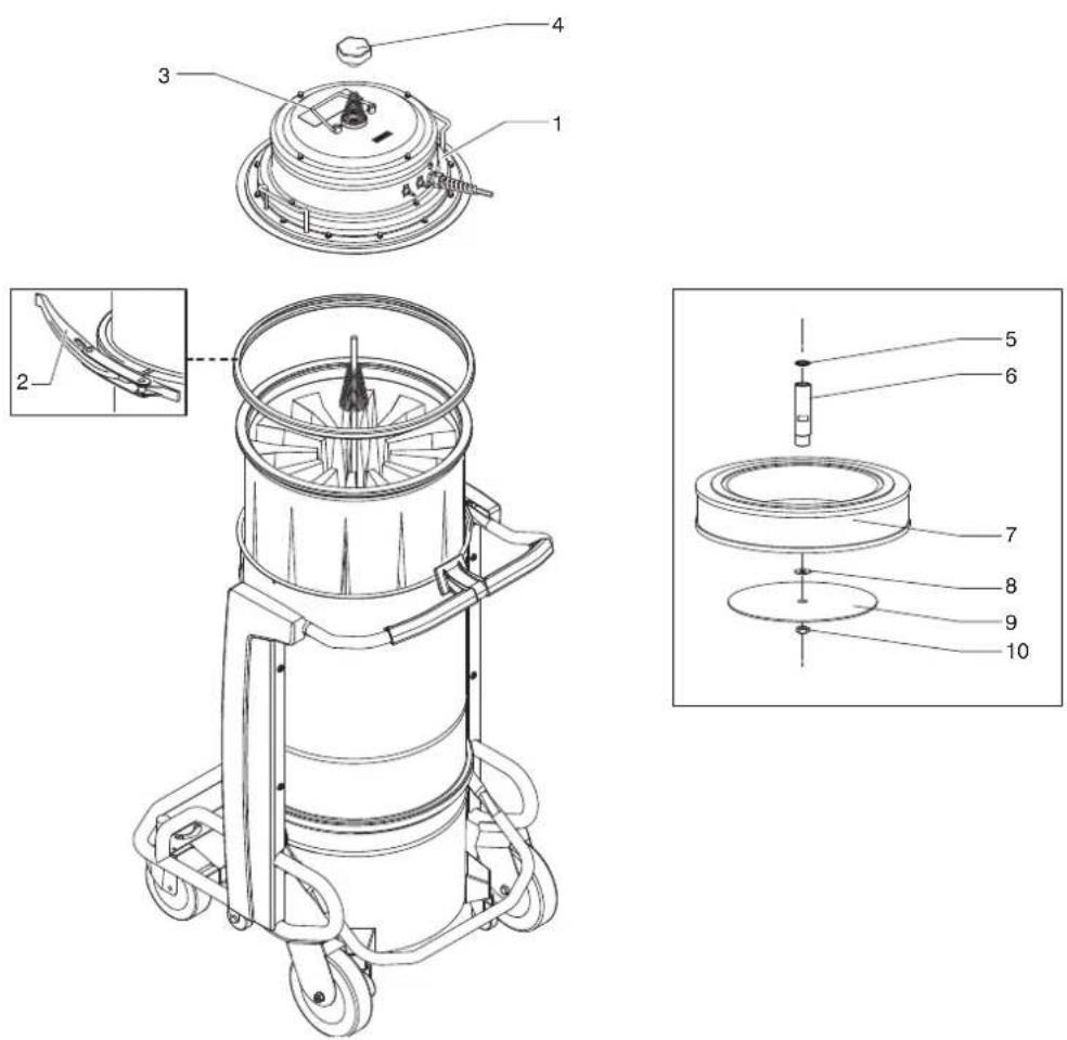
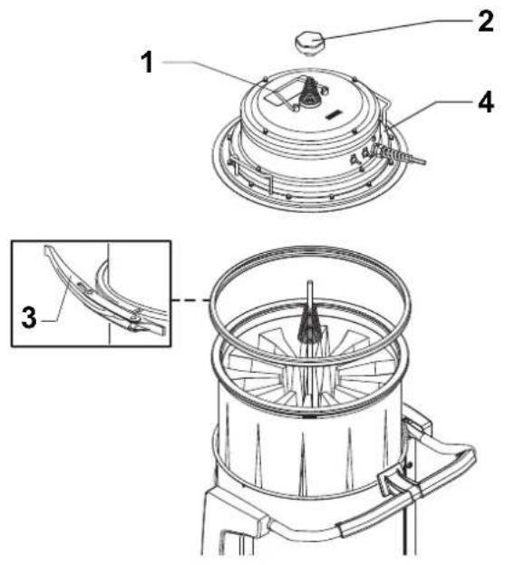
Upstream absolute filter replacement
Figure 10
■ Release the stop (3) and unscrew the filter shaker knob (4), release the closing band (2) and remove the head (1).
■ Unscrew the nut (10), remove the disc (9) and the gasket (8).
■ Replace the filter (7) and proceed in the reverse order to reassemble the head.
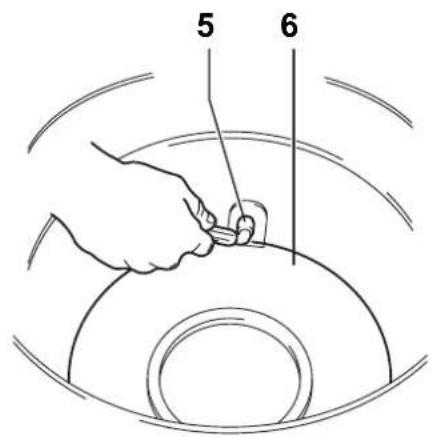
Installation, cleaning and replacement of the separator (optional)
Figure 11
[ NOTE ]
Instructions describing how to fit the optional kits and the relative operation and maintenance manuals are supplied together with the optional kits.
[ NOTE ]
If there is only a dust deposit on the separator (4) allow the dust to drop through the central hole.
The separator (4) should first be disassembled in order to be perfectly cleaned:
■ Release the stop (3) and unscrew the filter shaker knob (4), release the closing band (2) and remove the head (1).
■ Remove the filter.
■ Unscrew the two screws (5) and remove it from the container.
■ Replace the part if it is excessively worn.
■ Reinstall the separator (6).
■ Lock it and fix it by means of the two screws (5).
■ Reinstall the filter and the deck.
Tightness inspection
Hoses check
Figure 12
Make sure that connecting hoses (1) are in a good condition and correctly fixed.
If the hoses are damaged, broken or badly connected to the unions, they must be replaced.
When sticky materials are treated, check for possible clogging along the hose, in the inlet and on the baffle plate inside the filtering chamber.
To clean, scrape the inlet (2) from the outside to remove deposits.
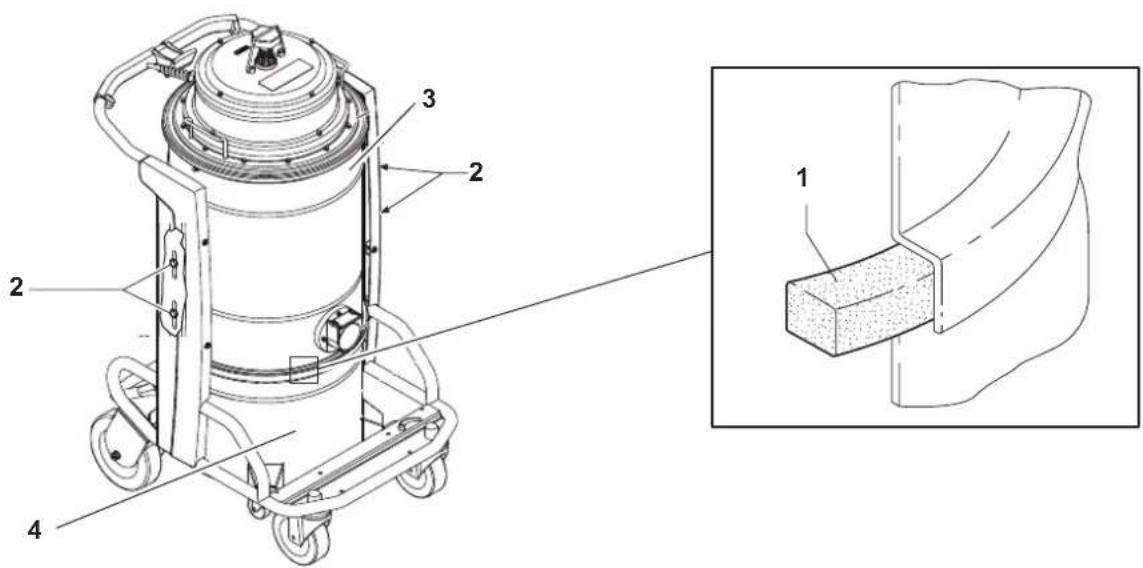
Filtering chamber gasket check for machines equipped with dust container
Figure 13
If the gasket (1) between the container and the filtering chamber (3) fails to guarantee tightness:
■ Loosen the four screws (2) that lock the filtering chamber (3) against the machine structure.
■ Allow the filtering chamber (3) to lower down and tighten the screws (2) once it has reached the tightness position.
If an optimal seal is not yet obtained or if there are tears, cracks, etc., the gasket must be replaced.
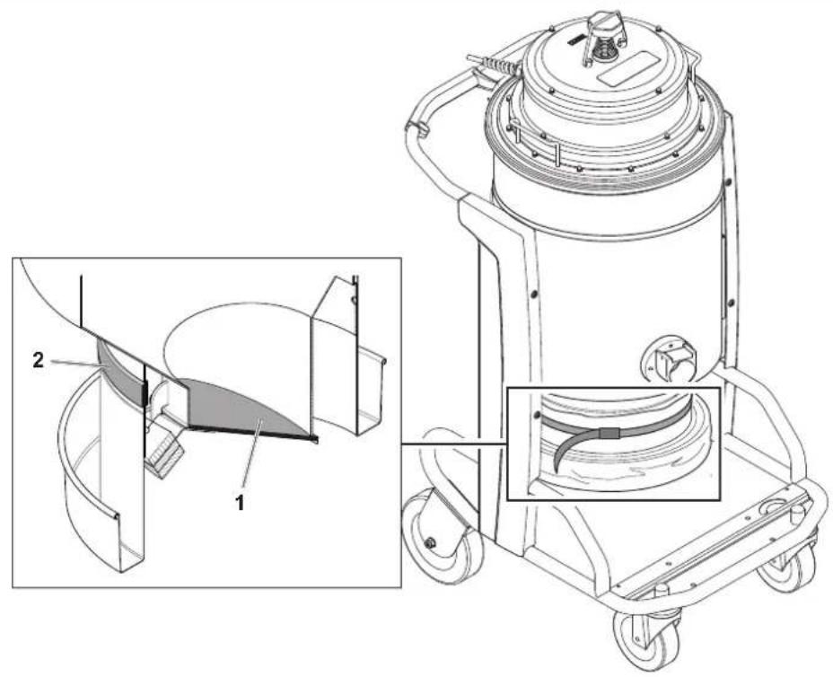
Filtering chamber gasket check for machines equipped with Longopac® system
Figure 14
Ensure that the Longopac® bag is tight with the gasket (2).
Also check the seal of the gasket positioned on the discharge clapet (1).
The gasket must be replaced if it is torn, cut, etc...
Disposal
Figure 15
The crossed-out wheeled bin symbol on the equipment indicates that used electrical and electronic equipment must be collected and disposed of separately from household waste. The correct disposal of the equipment will help prevent potential negative consequences for the environment and human health.
Electrical and electronic household equipment must be disposed of at the separate collection points in the residence area. Please note that commercial electrical and electronic equipment should be disposed of separately from the municipal waste stream. We will be pleased to inform you about suitable disposal options.
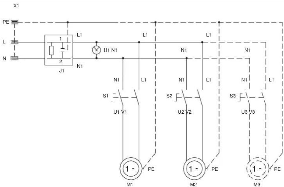
Wiring diagrams
Figure 16
Recommended spare parts
The following is a list of spare parts that should be kept ready at hand in order to speed up maintenance operations.
Refer to the manufacturer's spare parts catalogue when ordering spare parts.
| Name | Model | ||
| Standard Filter | “M” | ||
 | Star filter kit 40000338 40000699 | ||
 | Filter ring gasket Z8 17026 | ||
 | Filter chamber gasket 40000762 | ||
 | Filter clamp Z8 18079 | ||
 | Absolute filter Z8 17455 | ||
 | Dust bag Z8 40099 | ||
 | Longopac® 4084000956 | ||
 | 230V 1000W Motor 40000937 | ||
| 110V 1000W Motor 40000938 | |||
 | Brushes (carbon) for 230V 1000W motors (2 brushes) 40000885 | ||
| Brushes (carbon) for 120V 1000W motors (2 brushes) 40000886 | |||
GB
Troubleshooting
| Problem Cause Remedy | ||
| The machine does not start Lack of power supply | Check for power at the socket.Check the condition of the socket and the cable.Ask for assistance to be performed by a qualified manufacturer's technician. | |
| The machine revolutions increase | Clogged primary filter | Turn on the filter shaker. Replace it if this is not sufficient. |
| Clogged vacuum hose | Check the vacuum hose and clean it. | |
| The machine produces a more acute noise The liquid mechanical stop has activated Emptying of the liquid container. | ||
| Dust leaks from the machine | The filter is torn Replace it with another of identical type. | |
| Inadequate filter | Replace it with another of a suitable category and check. | |
| Noisy motors Motor brushes (carbon) worn or broken | Remove and replace the (carbon) motor brushes. | |
| Electrostatic current on the machine Missing or inefficient grounding | Check all ground connections. In particular on the vacuum inlet fitting; replace the hose with an antistatic hose. | |
GB
GB
2
3
9
10
11
12
natural_image
Line drawing of a cylindrical industrial machine with wheels and control panel (no text or symbols)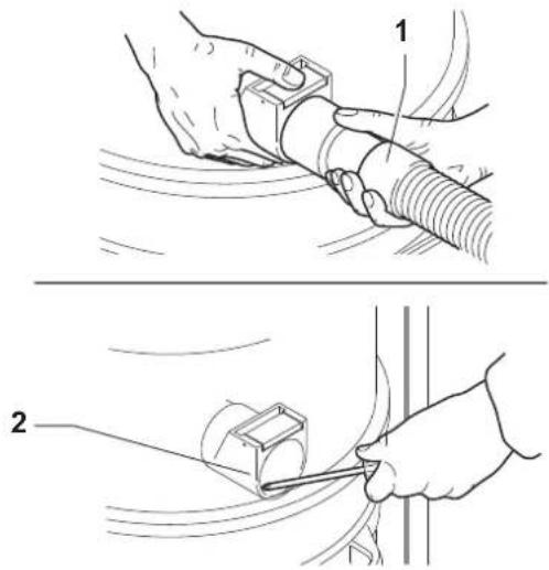
13
14
natural_image
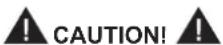
Technical line drawing of a vacuum cleaner with labeled components and an inset view showing internal structure (no text or symbols present)15
natural_image
Symbol of a trash bin crossed with a diagonal line, no text or numbers present16
17
Nilfisk®
CEDI 042518
Ec Declaration of Conformity - Enclosure II 14 - 2006/42
Eu Konfermitserklaering - Annals II 2006/42/FC
L'Vastagouse-Indikratscon - Tocnuse II, A. 2706/02
We declare under our own responsibility that the machines
Workser henned under fukt, answer at maskne
Apieonism de muso albodico, ke masos
Eke kunnams je osname enels vastulvel, et nos nivskantamme omals vastuallserme että kore
Bis pacinojam, sackand ar minu pastu athildia, ta mašiva
Nudukaraw tom Fessenskorsa, 11 mag.
Fermesfarkas of the past year's season. If all the members
Felskossagank transatlan cuninkluk hogs gap
The following table is in English:
- The following table provides the original data:

natural_image
Simple geometric diagram with a rectangle and diagonal line, no text or symbols present
Nilfisk S.P.A.
II Directure Generic The Group
The General Manager
111804

- Translation of the original instructions
- Table of contents
- Instructions for use....2
- Description of the machine ....5
- Maintenance, cleaning and decontamination....10
- Recommended spare parts ....14
- Troubleshooting....15
- Instructions for use
- Operator's safety
- CAUTION!
- General information for using the machine
- Proper uses
- Improper Use
- Versions and variations
- HEPA variants
- General recommendations
- [ NOTE ]
- Residual Risks
- DANGER
- FORBIDDEN
- MANDATORY
- ■ Risks to the presence of residual high temperature after stopping the vacuum unit.
- EC Declaration of conformity
- Description of the machine
- Machine Parts and Labels
- Figure 1
- Optional kits
- Accessories
- Packing and unpacking
- Unpacking, moving, use and storage
- Setting to work - connection to the power supply
- NOTE
- Extensions
- Dry applications
- Vacuuming of liquids
- Dimensions
- Controls and indicators
- Figure 4
- Start/stop switch
- Power indicator
- Manual filter shaker knob
- Inspections prior to starting
- Figure 5
- Vacuum inlet
- Starting and stopping
- Emergency stopping
- Operation
- At the end of a cleaning session
- Maintenance, cleaning and decontamination
- Primary filter cleaning with manual system
- Emptying the container
- Figure 6
- Emptying of the liquid container
- Dust Bag
- Figure 7
- Longopac® bag for dust collection
- Figure 8
- Replacement of dust bags
- How to replace the Dust Bag
- How to replace the Longopac®
- Main and absolute filter disassembly and replacement
- Primary filter replacement, for machines equipped with manual cleaning system
- Figure 9
- Upstream absolute filter replacement
- Figure 10
- Installation, cleaning and replacement of the separator (optional)
- Figure 11
- Tightness inspection
- Hoses check
- Figure 12
- Filtering chamber gasket check for machines equipped with dust container
- Figure 13
- Filtering chamber gasket check for machines equipped with Longopac® system
- Figure 14
- Disposal
- Figure 15
- Wiring diagrams
- Figure 16
- Recommended spare parts
- Nilfisk®
Brand : NILFISK
Model : S3B
Category : Vacuum Cleaner