TR6000R - Boiler BOSCH - Free user manual and instructions
Find the device manual for free TR6000R BOSCH in PDF.
User questions about TR6000R BOSCH
0 question about this device. Answer the ones you know or ask your own.
Ask a new question about this device
Download the instructions for your Boiler in PDF format for free! Find your manual TR6000R - BOSCH and take your electronic device back in hand. On this page are published all the documents necessary for the use of your device. TR6000R by BOSCH.
USER MANUAL TR6000R BOSCH
Tronic 4000 | 5000 | 6000 | 7000
TR4000 18|21|24|27EB - TR5000 13|18|21|24|27 EB - TR6000R 18/21|24/27 ESOB TR7000 15/18|21/24|24/27 DESOB - TR7000R 18/21|24/27 DESOB
natural_image
Exterior view of a Bosch Comfort Plus air conditioner unit (no visible text or symbols beyond branding)
natural_image
White Bosch air conditioner unit with control knob (no visible text or symbols beyond brand logo)Table of Contents 1 Safety information
1 Safety information....8
2 Installation instructions ....10
2.1 Installation .... 10
3 Technical data....11
3.1 Solar heated .... 12
4 Special accessories....13
5 Environmental protection/disposal ....13
6 Data Protection Notice ....13
This appliance is intended for domestic use and the household environment only.
Please read this installation instruction manual carefully, then act accordingly! Store for future reference. These installation instructions must be included when transferring this appliance to a new owner.
- The appliance may only be connected and put into operation by a qualified professional.
• Install and operate the appliance as described in the text and illustrations. We do not accept liability for damage resulting from failure to read these instructions. - This appliance is intended for use up to an altitude of 2000 m above sea level.
- The appliance may only be installed and stored in a frost-free room (due to residual water).

WARNING
The supplied water connection nozzles must be used and installed as shown in the supplementary sheets. Make sure that a check valve is installed in the cold water supply line.

WARNING
Risk of electric shock!
Switch off the mains voltage supply immediately if a fault occurs.
Disconnect the power supply before opening the appliance.
Immediately shut off the cold water supply to the appliance should it leak.
These installation instructions are intended for plumbers, heating engineers and electricians. All instructions must be observed. Failure to comply with instructions may result in material damage and personal injury, including possible loss of life.
▶ Read the installation instructions (heat source, heating controller, etc.) before installation ( chapter 2).
▶ Observe the safety instructions and warnings.
▶ Observe national and regional regulations, technical rules and guidelines.
- The statutory regulations of the respective country, as well as those of the local electricity and water suppliers, must be adhered to.
- The continuous-flow heater is a Class I appliance and must be connected to the protective earth.
- The appliance must be permanently connected to installed pipes. The conductor cross-section must comply with the installed appliance power.

CAUTION
Earthed water pipes may give the appearance of a connected protective earth.
- To guarantee compliance to relevant safety regulations, an all-pole separator must be fitted during installation, according to chapter 3. The contact opening must be at least 3 mm.
- Ensure that the inlet water pressure, maximum and minimum, is according with the value specified by the manufacturer (→ chapter 3).
- For models TR 4000, TR 5000, TR 5000R the water inlet shall not be connected to inlet water obtained from any water heating system.
- For TR 6000R, TR 7000R and TR7000 appliances the cold water supply temperature must not be higher than 55^ .
- In accordance with EN60335-2-35, when the appliance is intended to supply water for showering, the output temperature must be limited to 55 °C, see fig. 9.
- The continuous-flow heater is only suitable for closed (pressurised) operation.
- The tap and outlet fittings must be approved for operation with closed (pressurised) continuous-flow heater systems.
- The water's specific electrical resistivity must not be less than 1300 cm. Ask the local water utility company regarding the electrical resistivity of the water.
- The continuous-flow heater is suitable for connection to DVGW-tested plastic pipes.
- Disconnect the electrical connection cable from the supply and shut off the water supply before connecting the appliance!
- Connect the water supply and then connect the electrical supply.
- Only make the openings which are required for installation on the rear of the appliance. If the appliance is reinstalled, the unused openings must be provided with watertight sealing.
- Do not touch electrically live parts after installation.
- Do not use aggressive or abrasive cleaning detergents!
- Do not use a steam cleaner.
Safety of electrical devices for domestic use and similar purposes
The following requirements apply in accordance with EN 60335-2-35 in order to prevent hazards from occurring when using electrical appliances:
"This appliance can be used by children of 3 years and older, as well as by people with reduced physical, sensory or mental capabilities or lacking in experience and knowledge, if they are supervised and have been given instruction in the safe use of the appliance and understand the resulting dangers. Children shall not play with the appliance. Cleaning and user maintenance must not be performed by children without supervision."
"If the power cable is damaged, it must be replaced by the manufacturer, its customer service department or a similarly qualified person, so that risks are avoided."
2 Installation instructions
• Install the appliance as shown in the illustrations. Observe the instructions in the text.
2.1 Installation
Unpacking/Removing the cover (Fig. 1)
- Unpack the appliance and check for transport damage. If any components are damaged, then do not connect the appliance.
- Check that your appliance contains all components included in the scope of delivery: appliance, installation set with supplementary sheets, installation instructions, operating instructions.
- Please dispose of the packaging and the old appliance in an environmentally-friendly manner.
- When removing the cover from either a Type or Type appliance, please note the following: The Type Cover is fastened by a central closure behind the service flap. The Type Cover is attached by two screws located on the underside of the cover.
Preparations for installation (Fig. 2)

WARNING
Important: Only use the supplied installation set.
The supplied water connection nozzles must be installed!
- Shut off water supply. The electrical connection (connection cable) must be disconnected from the power supply. Unscrew the fuse or switch off the circuit breaker.
• Install the water connection nozzles according to the instructions on the supplementary sheet. - The electrical connection cable can either be guided in at the top (X) or bottom (Y).
- The rear panel must lie against the cold water connection nozzle in the position provided for such (8.).
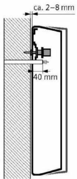
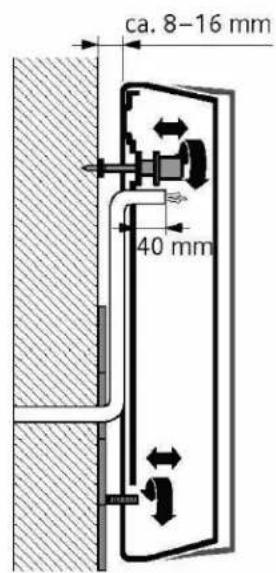
Wall mounting (Fig. 3)
- The grommet must tightly surround the connection cable. If it is damaged during mounting, the openings must be provided with watertight sealing.
- The electrical supply terminal can be fitted at the top (X) or bottom (Y). The sheath of the connection cable must extend for at least 40 mm into the appliance.
- The distance to the wall is variable. You can compensate for any unevenness of the wall's surface. With a distance to the wall of 8–16 mm, insert the spacer and install the extender (3.-5.).
- The appliance must be mounted securely on the wall in vertical position. If necessary, attach it at the lower adjustable screws (6.).
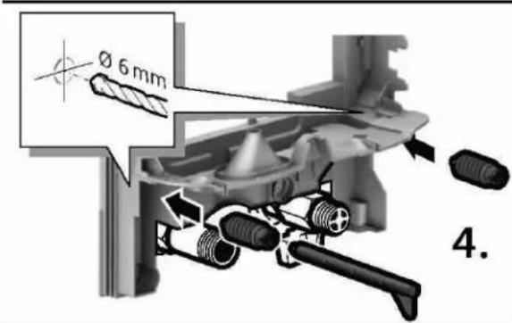
Water connection (Fig. 4)
- Connect the water supply, then open the cold water supply.
• The appliance must be vented. To do so, open the warm water tap fully and flush out the appliance thoroughly for 1 minute.
Electrical connection/Mounting (Fig. 5)
Limiting the outlet temperature to 53 °C if unit used for shower purposes.

WARNING
Risk of electric shock!
How to move the temperature limiting switch,
▶ Disconnect the power supply before opening the appliance.
▶ Remove the cover.
▶ Move the temperature limiting switch to the 53°C position ( Fig. 9).
- Only for appliances with power selector switches:
Set the power using the power selector switch before connecting the wires to the mains connection terminal: Nominal output power left, reduced output right (1.) and the set output marked on the ratings plate.
- Screw the wires tightly into the mains connection terminal.
- Switch on the safety limiter (3.)
- Install the cover - according to either Type or A instructions (4.-7.).
Installation note
- The installation of non plug-in ready appliances must be undertaken by the respective utility operator or by a qualified specialist company, who can also assist you when you are requesting the approval of the utility company for installation of the appliance.
Startup (Fig. 6)
The device is compliant to IEC 61000-3-12.
First start-up
- Switch on the fuses.
- Setting the temperature.
- Initial rinsing: Open the warm water tap fully and allow water to flow for at least 1 minute. Only then (for safety reasons) will the appliance begin to heat.
Tip: Should the appliance not start because of a reduced flow-rate, remove the perlator, shower head or similar from the water tap before start and repeat the process.
- Explain the operation of the appliance to the user.
Additional information (Fig. 7)
- If the appliance does not have sufficient water flow due to low water line pressure in your domestic plumbing system, remove the flow-rate limiter (1.-3.) or increase supply pressure to the system.
- The integrated flow restriction in the unit ensures a certain temperature increase in order to grant comfort, so removing this and in case the water pressure varies it can cause temperature fluctuations.
- The inlet filter must not be removed. It must always remain in the appliance even if flow restrictor is removed.
- Priority circuit for the combination with electrical storage heaters: For operation with a priority circuit, a special load shedding relay BZ 45L21 (special accessory) is required. Other existing load shedding relays, with the exception of electronic load shedding relays, may malfunction (Wiring diagram).
- The control electronics must be coded when operated with a load shedding relay. Remove the keying nose on the electronics (4.).
• After anytime the unit is disconnected from power, e.g. at initial operation, power failures, air bubble detected, 6 l/min of water have to flow through appliance once. Only after this rinsing, the appliance starts heating up. The reason for this behavior is to remove air bubbles inside the heating element so a damage of the heating coils can be avoided. - The safety limiter (SL) disconnects all electrical components in the event of a over-pressure or temperature. When the cause of the
actuation has been found / eliminated, the SL can be switched on again by pressing the lock down button. Water pressure peaks in installation due to flushing systems, pumping systems could trigger
the SL, so pressure regulation valves are advised at supply line in order to minimize possible perturbations.
* Larger cable cross-sections may be required depending on the connection configuration.
| - | TR400018 EB | TR400021 EB | TR400024 EB | TR400027 EB | ||
| Rated output [kW] 18 21 24 27 | ||||||
| Rated voltage [V] 400 400 400 400 | ||||||
| Fuse protection [A] 32 32 40 40 | ||||||
| Minimum conductor cross-section* [mm | 2] 4 4 6 6 | |||||
| Warm water flow at rated output with temperature increase from 12 °C to 38 °C (without flow-rate limiter) | [l/min] | 9.8 | 11.6 | 13 | 14.6 | |
| 12 °C to 38 °C (with flow-rate limiter) | [l/min] | 6.5 | 7.6 | 8.7 | 9.3 | |
| 12 °C to 60 °C | [l/min] | 5.3 | 6.2 | 7.1 | 7.9 | |
| Start-up flow | [l/min] | 2.5 | 2.5 | 2.5 | 2.5 | |
| Start-up flow pressure** | [MPa (bar)] | 0.04 | 0.04 | 0.04 | 0.04 | |
| 0.4 | 0.4 | 0.4 | 0.4 | |||
| Application area in water specific electric resistance at 15 °C | [Ωcm] | ≥ 1 300 | ≥ 1 300 | ≥ 1 300 | ≥ 1 300 | |
| Rated pressure | [MPa (bar)] | 1.0 (10) | 1.0 (10) | 1.0 (10) | 1.0 (10) | |
| Maximum permissible supply temperature | [°C] | 20 | 20 | 20 | 20 | |
| Maximum mains impedance at connection point | [Ω] | 0.104 | 0.104 | 0.104 | 0.104 | |
| Energy efficiency class | AAAA | |||||
| Load profile | S | S | S | S | ||
| Annual energy consumption | [kWh] | 479 | 477 | 477 | 479 | |
| Daily energy consumption | [kWh] | 2,204 | 2,195 | 2,191 | 2,204 | |
| Sound power level | [dB] 15 15 15 15 | |||||
| Hot water heating energy efficiency | [%] | 39 | 39 | 39 | 39 | |
| TR500011/13 EB | TR500015/18 EB | TR5000R18/21 EB | TR500021/24 EB | TR500024/27 EBTR5000R24/27 EB | ||
| Rated output | [kW] | 11/13 | 15/18 | 18/21 | 21/24 | 24/27 |
| Rated voltage [V] 400 400 400 400 | ||||||
| Fuse protection [A] 25 32 32 | 40 40 | |||||
| Minimum conductor cross-section* [mm | 2] | 2.5 | 4 4 6 6 | |||
| Warm water flow at rated output with temperature increase from 12 °C to 38 °C (without flow-rate limiter) | [l/min] | 6.0/7.1 | 8.1/9.8 | 9.8/11.6 | 11.6/13.0 | 13.0/14.6 |
| 12 °C to 38 °C (with flow-rate limiter) | [l/min] | 5 | 6.5 | 7.6 | 8.7 | 9.3 |
| 12 °C to 60 °C | [l/min] | 3.3/3.8 | 4.4/5.3 | 5.3/6.2 | 6.2/7.1 | 7.1/7.9 |
| Start-up flow | [l/min] | 2.5 | 2.5 | 2.5 | 2.5 | 2.5 |
| Start-up flow pressure** | [MPa (bar)] | 0.04 | 0.04 | 0.04 | 0.04 | 0.04 |
| 0.4 | 0.4 | 0.4 | 0.4 | 0.4 | ||
| Application area in water specific electric resistance at 15 °C | [Ωcm] | ≥ 1 300 | ≥ 1 300 | ≥ 1 300 | ≥ 1 300 | ≥ 1 300 |
| Rated pressure | [MPa (bar)] | 1.0 (10) | 1.0 (10) | 1.0 (10) | 1.0 (10) | 1.0 (10) |
| Maximum permissible supply temperature | [°C] | 20 | 20 | 20 | 20 | 20 |
| Maximum mains impedance at connection point | [Ω] | 0.433 | 0.067/0.104 | 0.067/0.104 | 0.067/0.104 | 0.067/0.104 |
| Energy efficiency class | AAAA | A | ||||
| Load profile | XS | S | S | S | S | |
| Annual energy consumption | [kWh] | 471 | 479 | 477 | 477 | 479 |
| Daily energy consumption | [kWh] | 2,160 | 2,204 | 2,195 | 2,191 | 2,204 |
| Sound power level | [dB] | 15 | 15 | 15 | 15 | 15 |
| Hot water heating energy efficiency | [%] | 39- | 39TR700015/18 DESOB | 39TR6000R18/21 ESOBTR7000R18/21 DESOB | 39TR700021/24 DESOB | 39TR7000 24/27 DESOBTR6000R 24/27 ESOBTR7000R 24/27 DESOB |
| Rated output [kW] 15/18 18/21 21/24 24/27 | ||||||
| Rated voltage [V] 400 400 400 400 | ||||||
| Fuse protection [A] 32 32 40 40 | ||||||
| Minimum conductor cross-section* | [mm2] | 4 | 4 | 6 6 | ||
| Warm water flow at rated outputwith temperature increase from12 °C to 38 °C (without flow-rate limiter) | [l/min] | 8.1/9.8 | 9.8/11.6 | 11.6/13.0 | 13.0/14.6 | |
| 12 °C to 38 °C (with flow-rate limiter) | [l/min] | 6.5 | 7.6 | 8.7 | 9.3 | |
| 12 °C to 60 °C | [l/min] | 4.4/5.3 | 5.3/6.2 | 6.2/7.1 | 7.1/7.9 | |
| Start-up flow | [l/min] | 2.5 | 2.5 | 2.5 | 2.5 | |
| Start-up flow pressure** | [MPa (bar)] | 0.04 | 0.04 | 0.04 | 0.04 | |
| 0.4 | 0.4 | 0.4 | 0.4 | |||
| Application area in waterspecific electric resistance at 15 °C | [Ωcm] | ≥ 1 300 | ≥ 1 300 | ≥ 1 300 | ≥ 1 300 | |
| Rated pressure | [MPa (bar)] | 1.0 (10) | 1.0 (10) | 1.0 (10) | 1.0 (10) | |
| Maximum permissible supply temperature | [°C] | 55 | 55 | 55 | 55 | |
| Maximum mains impedance at connection point | [Ω] | 0.067/0.104 | 0.067/0.104 | 0.067/0.104 | 0.067/0.104 | |
| Energy efficiency class | A | A | A | A | ||
| Load profile | S | S | S | S | ||
| Annual energy consumption | [kWh] | 479 | 477 | 477 | 479 | |
| Daily energy consumption | [kWh] | 2,204 | 2,195 | 2,191 | 2,204 | |
| Sound power level | [dB] | 15 | 15 | 15 | 15 | |
| Hot water heating energy efficiency | [%] | 39 | 39 | 39 | 39 |
** The pressure loss on the mixer must also be added.
3.1 Solar heated
Only for appliances that are suitable for solar heating systems:
The appliance can only heat prewarmed water to a max. of 60°C.
If the cold water supply exceeds a temperature of 55^ C, the water will not be warmed any further.
Important: The cold water supply temperature must not be higher than 55 °C!
If the cold water supply exceeds a temperature of 60^ , a circuit breaker will trigger and shut the appliance off. Therefore, the residential plumbing must be equipped with a thermostatic premixer that will limit the cold water supply temperature to a max. of 55^ by appropriately mixing in cold water.
Dimensions (Fig. 8)
4 Special accessories
- Priority switch (load shedding relay) BZ 45L21: for operation with a priority circuit
• Mounting kit BZ 45K23: for surface mount installation - Only for appliances that are suitable for solar heating systems:
Thermostatic premixer for installation in the domestic plumbing when using preheated water
5 Environmental protection/disposal
Environmental protection is a fundamental corporate strategy of the Bosch Group.
The quality of our products, their economy and environmental safety are all of equal importance to us and all environmental protection legislation and regulations are strictly observed.
We use the best possible technology and materials for protecting the environment taking account of economic considerations.
Packaging
Where packaging is concerned, we participate in country-specific recycling processes that ensure optimum recycling.
All of our packaging materials are environmentally compatible and can be recycled.
Used appliances
Used appliances contain valuable materials that can be recycled.
The various assemblies can be easily dismantled. Synthetic materials are marked accordingly. Assemblies can therefore be sorted by composition and passed on for recycling or disposal.
Used electrical and electronic appliances
Electrical or electronic devices that are no longer serviceable must be collected separately and sent for environmentally compatible recycling (in accordance with the European Waste Electrical and Electronic Equipment Directive).
To dispose of old electrical or electronic devices, you
should use the return and collection systems put in place in the country concerned.
Batteries must not be disposed together with your household waste.
Used batteries must be disposed of in local collection systems.
6 Data Protection Notice

We, Bosch Thermotechnology Ltd., Cotswold Way, Warndon, Worcester WR4 9SW, United Kingdom process product and installation information, technical and connection data, communication data, product registration and client history data to provide product functionality (art. 6 (1) sentence 1 (b)
GDPR), to fulfil our duty of product surveillance and for product safety and security reasons (art. 6 (1) sentence 1 (f) GDPR), to safeguard our rights in connection with warranty and product registration questions (art. 6 (1) sentence 1 (f) GDPR) and to analyze the distribution of our products and to provide individualized information and offers related to the product (art. 6 (1) sentence 1 (f) GDPR). To provide services such as sales and marketing services, contract management, payment handling, programming, data hosting and hotline services we can commission and transfer data to external service providers and/or Bosch affiliated enterprises. In some cases, but only if appropriate data protection is ensured, personal data might be transferred to recipients located outside of the European Economic Area. Further information are provided on request. You can contact our Data Protection Officer under: Data Protection Officer, Information Security and Privacy (C/ISP), Robert Bosch GmbH, Postfach 30 02 20, 70442 Stuttgart, GERMANY.
You have the right to object, on grounds relating to your particular situation or where personal data are processed for direct marketing purposes, at any time to processing of your personal data which is based on art. 6 (1) sentence 1 (f) GDPR. To exercise your rights, please contact us via privacy.ttgb@bosch.com To find further information, please follow the QR-Code.
- First rinse: open the hot water tap and allow the water to run for at least 1 minute. The device will only start heating up (for safety reasons).
Savet: Ukoliko se uredaj ne pokrene zbog smanjenog protoka vode, uklonite perlator, glavu tuša ili slično pre nego što počnete i ponovite postupak.
- Objasnite rad aparata korisniku.
text_image
Technical diagram illustrating cable installation and component assembly with labeled parts and dimensional annotationsX
text_image
ca. 2-8 mm 40 mmX
text_image
ca. 8-16 mm 40 mm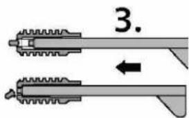
text_image
3.
text_image
Ø 6 mm 4.
text_image
5. 6.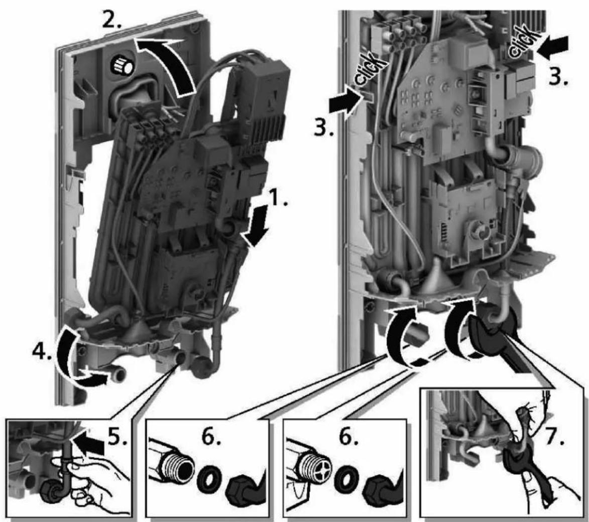
text_image
Technical diagram illustrating the assembly of a mechanical component with numbered parts and directional arrows indicating motion or assembly.1 Minute entlüften!
Vent for one minute!
natural_image
Industrial equipment component with a marked cross symbol and circular arrow, no readable text or labels present.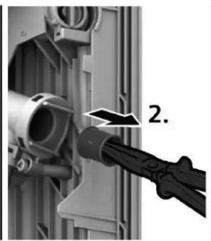
natural_image
Close-up of a mechanical component with a tool inserted, showing a pipe connection (no text or symbols visible)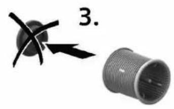
natural_image
Two mechanical components: a circular component with cross-shaped features and a threaded cylindrical component (no text or symbols)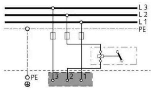
text_image
L 3 L 2 L 1 PE PE 3 2 1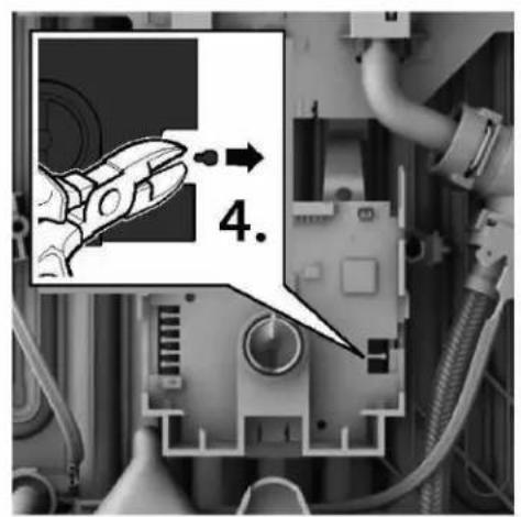
text_image
4.
natural_image
Exterior view of a white industrial air conditioner unit (no visible text or symbols)
natural_image
White industrial water heater with control knob (no visible text or symbols)
natural_image
White industrial appliance with digital display and control knob (no visible text or symbols)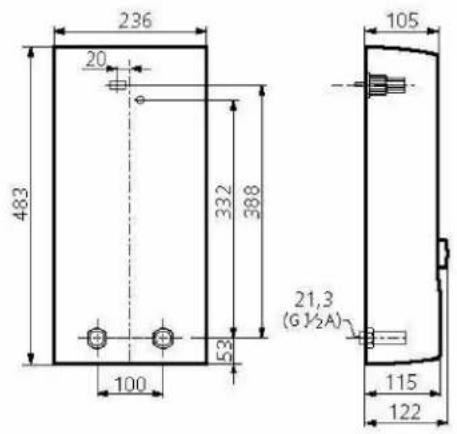
text_image
236 20 483 332 388 53 100 105 21,3 (G ½A) 115 122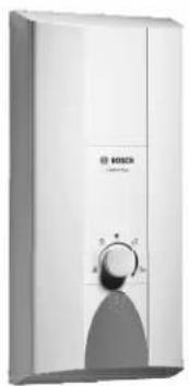
natural_image
Exterior view of a white Bosch air conditioner unit with control knob (no visible text or symbols)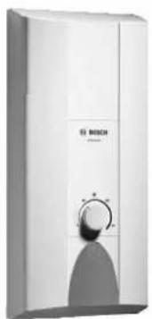
natural_image
Exterior view of a white Bosch air purifier unit with control knob (no text or symbols visible)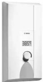
natural_image
White industrial water heater with digital display showing 385°C, no visible text or symbols on the device itself.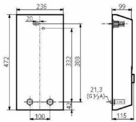
text_image
236 20 472 332 388 100 42 99 21,3 (GY2A) 115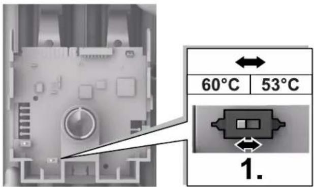
text_image
60°C 53°C 1.