B215 - Cassette tape REVOX - Free user manual and instructions
Find the device manual for free B215 REVOX in PDF.
| Product type | Stereo cassette tape deck |
| Brand | Revox |
| Model | B215 |
| Dimensions (W x H x D) | 450 x 153 x 332 mm |
| Weight | 9.15 kg |
| Power supply | 100/120/140/200/220/240 V AC, switchable, ±10%, 50-60 Hz, max. 45 W |
| Mains fuse | 100-140 V: T 500 mA; 200-240 V: T 250 mA |
| Tape speed | 4.76 cm/s |
| Wow and flutter | < 0.1% (DIN 45507 / IEC 386) for C60 and C90 |
| Usable cassettes | C46 to C120 (specifications guaranteed up to C90) |
| Motors | 4 motors: 2 µp-controlled DC reel motors, 2 quartz-driven direct-drive capstans |
| Frequency response (rec./play at -20 dB) | Type I: 30 Hz - 18 kHz ±3 dB; Type II/IV: 30 Hz - 20 kHz ±3 dB |
| Signal-to-noise ratio (with Dolby C, ref. 3% distortion) | Type I: >70 dB(A); Type II/IV: >72 dB(A) |
| Noise reduction systems | Switchable Dolby B and Dolby C |
| Modulation level | 200 nWb/m for 0 dB |
| Audio input (AUDIO INPUT) | Sensitivity: 50 mV / 100 kΩ, adjustable in 60 steps of 1 dB |
| Audio output (AUDIO OUTPUT) | 0.775 V / 1.5 kΩ |
| Headphone output (PHONES) | Jack socket, max. 2.8 V / 220 Ω, adjustable in 7 steps |
| Calibration | Automatic (ALIGN) for each tape type, 6 memory locations |
| Tape counter | Real time in minutes and seconds, dependent on cassette length |
| Special functions | Locator with 2 addresses, loop mode (LOOP), recording fade (FADE IN/OUT), timer, infrared remote control, serial link (SERIAL LINK) |
| Maintenance and cleaning | Clean the capstans, pinch rollers, magnetic heads, and tape guides; demagnetize occasionally |
| Safety | Do not obstruct the ventilation slots; protect from moisture and excessive heat; unit is not disconnected from mains in standby |
| Included accessories | Mains cable, manuals (FR/DE/EN) |
Frequently Asked Questions - B215 REVOX
User questions about B215 REVOX
0 question about this device. Answer the ones you know or ask your own.
Ask a new question about this device
Download the instructions for your Cassette tape in PDF format for free! Find your manual B215 - REVOX and take your electronic device back in hand. On this page are published all the documents necessary for the use of your device. B215 by REVOX.
USER MANUAL B215 REVOX
text_image
COUNTER PEAK PROGRAM INDICATOR 02:15REVOx


text_image
APPROD REMOTE CONTROLLED SYSTEM PAGE 04 19 KAR STOF 2010 PAPER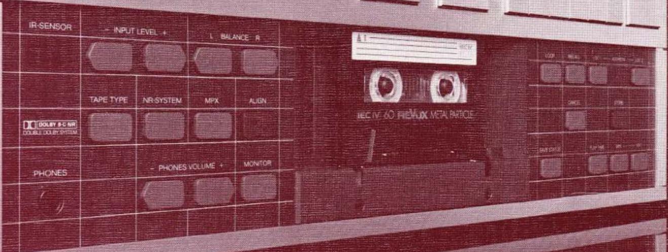
text_image
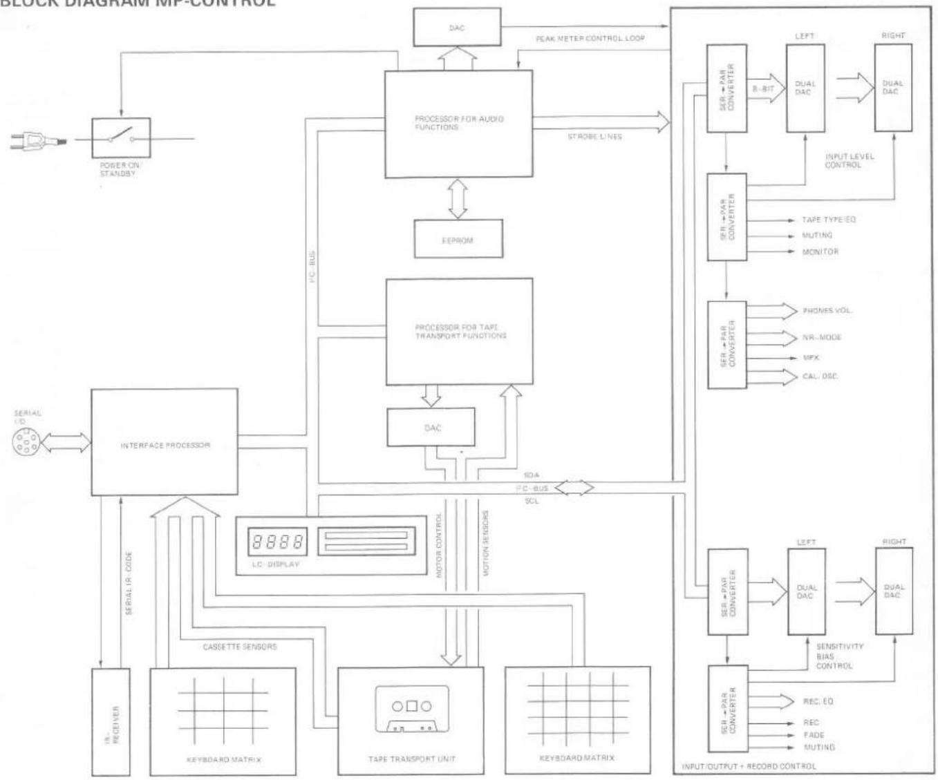
IR-SENSOR INPUT LEVEL + BALANCE R TEC IV 60 HEMUX METAL PARTICLE TAPE TYPE NR-SYSTEM MPX ALIGN DO DOLBY 9-C NR DOUBLE DOLBY SYSTEM PHONES PHONES VOLUME MONITORBLOCK DIAGRAM MP-CONTROL
flowchart
graph TD
    A["Power On Standby"] --> B["POWER ON STANDBY"]
    B --> C["PROCESSOR FOR AUDIO FUNCTIONS"]
    C --> D["EEPROM"]
    C --> E["PROCESSOR FOR TAPE TRANSPORT FUNCTIONS"]
    E --> F["DAC"]
    F --> G["INTERFACE PROCESSOR"]
    G --> H["CASSETTE SENSORS"]
    H --> I["KEYBOARD MATRIX"]
    I --> J["TAPE TRANSPORT UNIT"]
    J --> K["KEYBOARD MATRIX"]
    K --> L["CELL-DC"]
    L --> M["SER+PAR CONVERTER"]
    M --> N["DUAL DAC"]
    N --> O["INPUT/OUTPUT + RECORD CONTROL"]
    O --> P["SSENSITIVITY BIAS CONTROL"]
    P --> Q["DUAL DAC"]
    Q --> R["LEFT"]
    R --> S["DUAL DAC"]
    S --> T["RIGHT"]
    T --> U["SER+PAR CONVERTER"]
    U --> V["DUAL DAC"]
    V --> W["INPUT LEVEL CONTROL"]
    W --> X["TAPE TYPE EQ"]
    W --> Y["MUTING"]
    W --> Z["MONITOR"]
    W --> AA["PHONES VOL."]
    W --> AB["NR-MODE"]
    W --> AC["MPX"]
    W --> AD["CAL, DISC"]
    E --> AE["SOA"]
    E --> AF["P-C-BUS"]
    E --> AG["SCL"]
    G --> AH["LIC- DISPLAY"]
    AH --> AI["SER+PAR CONVERTER"]
    AI --> AJ["DUAL DAC"]
    AJ --> AK["INPUT/OUTPUT + RECORD CONTROL"]
    AK --> AL["SSENSITIVITY BIAS CONTROL"]
    AL --> AM["DUAL DAC"]
    AM --> AN["LEFT"]
    AN --> AO["DUAL DAC"]
    AO --> AP["INPUT/OUTPUT + RECORD CONTROL"]
Warning: This unit is not separated from the mains supply when switched off (STANDBY).
text_image
[11] B 215 • CASSETTE TAPE DECK REAL TIME COUNTER [10] PEAK PROGRAM INDICATOR [9] REVOX SET LEVEL FADE INPUT [8] [7] [6] [5] [4] [3] [2] [1] INFRARED REMOTE CONTROLLED SYSTEM PAUSE -04 PP PLAY STOP REC POWER IN RIVER PART TYPE NETHTEN LWP ALW DO NOT TO POTABLE PLATES VOLUME + MWC ON [25] [12] [13] [14] [15] [16] [17] [18] [19] [20] [21] [22] [23] [24] [26] [27] [28] [29] [30] [31] [32] [33] [34] [35]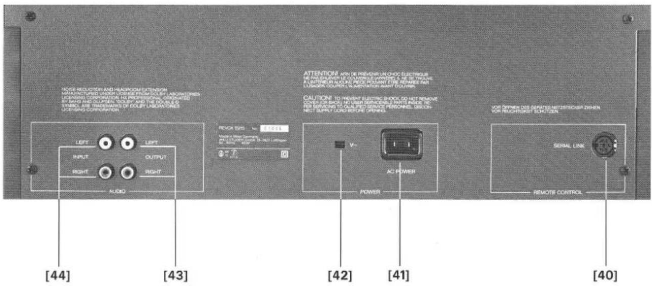
text_image
RIOG REDUCTION AND HEADROOM EXTENSION MANUFACTURED WORKS USING FROM DOULY LABORATORIES OPERATING CORPORATION (NO PROFESSIONAL ORGANATED) BY HANDS AND OILPEN TEXTURE AND THE ORDER SYMBOL ARE TRADEMANS OF DOULY LABORATORIES OPERATING CORPORATION. [44] [43] [42] [41] [40] REXOR SYS - to 5.8214 MODE IN WIRE DRINKS IN LUTTER FOR ON-NO LOPE V~ AC POWER POWER VOR OPENING DES GERATES METSTROKER DESHEN VOR RECHTRUST SCHUTZEN SERIAL LINK REMOTE CONTROLtext_image
R SENSOR - INPUT LEVEL - L BALANCE Rtext_image
REAL TIME COUNTER PEAK PROGRAM INDICATOR 12:35 MIN SEC SOURCE TYPE IV IF SENSOR INPUT LEVEL BALANCE R$$ I E C \parallel = + 4 d B $$
$$ I E C I V = + 6 \mathrm{dB} $$
text_image
P SENSOR INPUT LEVEL 1 SALANCE RWichtig:
text_image
REAL TIME COUNTER PEAK PROGRAM INDICATOR INPUT 1 2 -26 dB LOC DOLBYC PAUSE FADE L I B I I I I I I I I I I I I I I I I I I I I I I I I I I I I I I I I I I I I I I I I I I RECORD -30-20 -14-10 -6-4 -2 0+2+4+6+8 BAL R M D T Y P S U R SOURCE TYPE II
text_image
IN SEASON - INPUT LEVEL 4 C BALANCE 5text_image
REAL TIME COUNTER PEAK PROGRAM INDICATOR 1 LOC R2 TAPE DOLETHC LBB -30-35 -14-10-6-4-2 0+2+4+6+8 BAL RBB TYPE 8 SP SENSOR INPUT LEVEL 4 BALANCE 0natural_image
Interior view of an electronic device with visible circuitry and components (no readable text or symbols)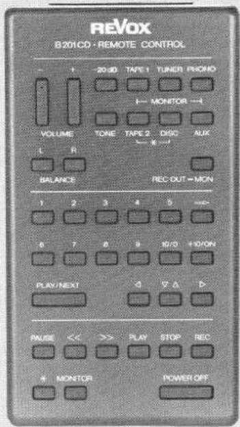
text_image
REVOX B201CD · REMOTE CONTROL - + - 20 dB TAPE 1 TUNER FRONO ← MONITOR → VOLUME TONE TAPE 2 DISC AUX L R ← × → BALANCE REC OUT = MON 1 2 3 4 5 ≈ 6 7 8 9 10/11+10/ON PLAY/NEXT △ ▼ △ △ PAUSE << >> PLAY STOP REC + MONITOR POWER OFF1 = GND
2 = GND (floating)
3 = serial I/O
4 = +5 V floating
5 = +5V 150mA max.
6 = n.c.
6. SCHALTUHRBETRIEB
natural_image
Diagram of a car interior with wheels and equipment, no text or symbols presentnatural_image
Pure electrical circuit lines without any symbolsNoise reduction and headroom extension manufactured under license from Dolby Laboratories Licensing Corporation. HX Professional originated by Bang and Olufsen. "Dolby" and the double-D symbol are trade marks of Dolby Laboratories Licensing Corporation.
Protect your cassette recorder from excessive heat and humidity. Install it in a location where the ventilating louvers are not obstructed. Please read the instructions in Section 1.2 before connecting the recorder to the AC supply.
GUARANTEE
A special guarantee request card is bypassed to all cassette recorders sold within the Federal Republic of Germany. This card is either located inside the packing or in a plastic pouch on the outside of the packing. Should this card be missing, please consult your REVOX dealer or your national REVOX distributor.
Guarantee cards for cassette recorders sold in Switzerland and Austria are issued directly by the authorized REVOX dealer.
Guarantee cards for cassette recorders sold in France are located inside the packing. This card must be completely filled out and signed by your authorized REVOX dealer.
Please note that the guarantee is only valid within the country in which the equipment has been sold. The guarantee becomes null and void if unauthorized modifications or unprofessional repairs are made.
PACKING
Please save the original packing material because its special construction provides optimum protection for your valuable equipment.
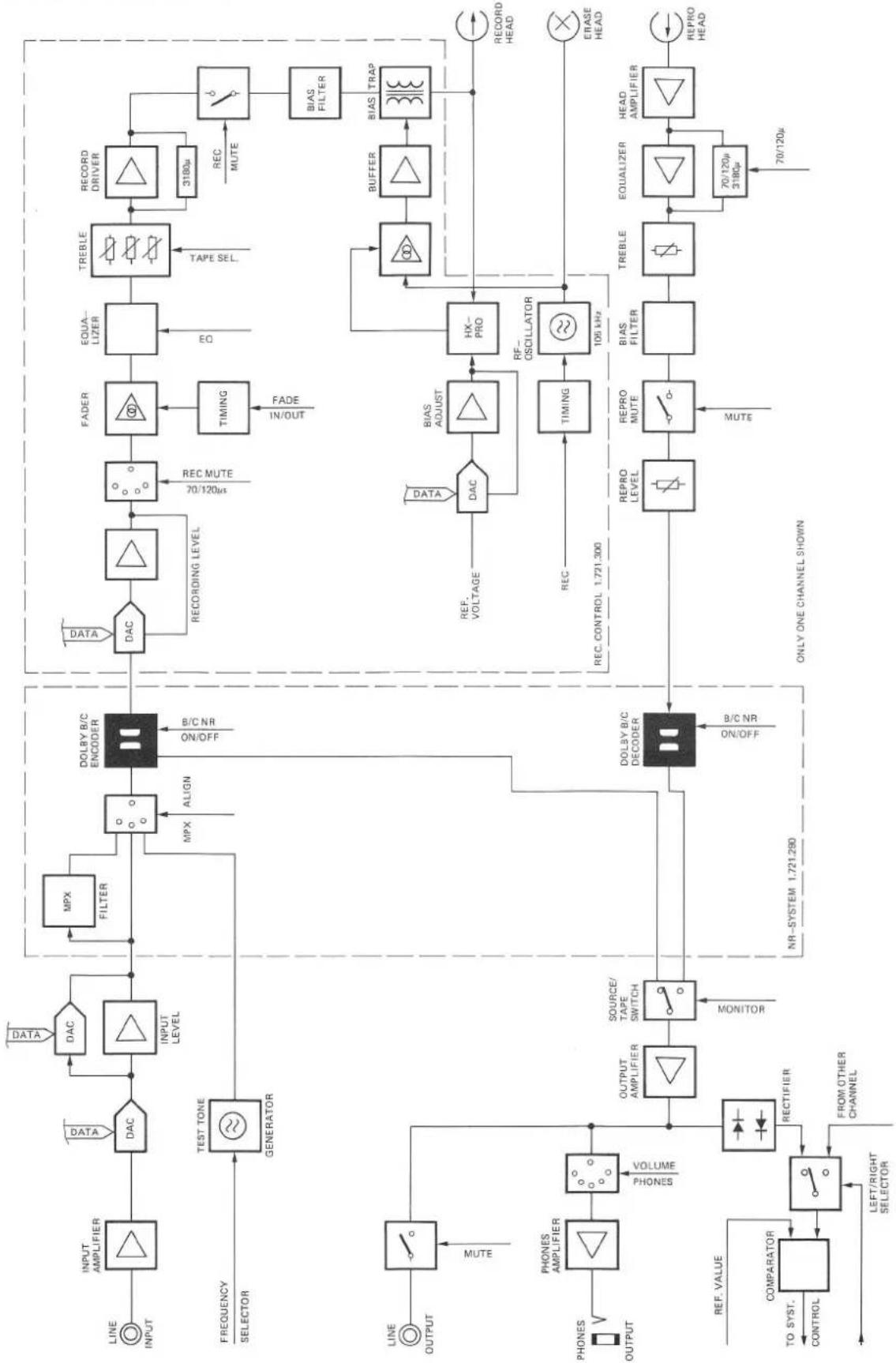
BLOCK DIAGRAM AUDIO SECTION
flowchart
graph TD
    A["LINE INPUT"] --> B["INPUT AMPLIFIER"]
    B --> C["DAC"]
    C --> D["INPUT LEVEL"]
    D --> E["MPX FILTER"]
    E --> F["DOLBY B/C ENCODER"]
    F --> G["DATA"]
    F --> H["REC MUTE"]
    H --> I["FADER"]
    I --> J["EQUA-LIZER"]
    J --> K["TREBLE"]
    K --> L["3180μ REC MUTE"]
    L --> M["BIAS FILTER"]
    M --> N["BIAS TRAP"]
    O["FREQUENCY SELECTOR"] --> P["TEST TONE GENERATOR"]
    P --> Q["LINE OUTPUT"]
    Q --> R["MUTE"]
    S["LINE OUTPUT"] --> T["PHONE AMPLIFIER"]
    T --> U["VOLUME PHONES"]
    U --> V["OUTPUT AMPLIFIER"]
    V --> W["SOURCE/TAPE SWITCH MONITOR"]
    W --> X["DOLBY B/C DECODER"]
    X --> Y["DATA"]
    X --> Z["REC VOLTAGE"]
    Z --> AA["DAC"]
    AA --> AB["BIAS ADJUST"]
    AB --> AC["RF-OSCILLATOR"]
    AC --> AD["TIMING"]
    AD --> AE["105 kHz"]
    AE --> AF["BIAS FILTER"]
    AF --> AG["BIOSURFACE SWITCH"]
    AH["PROVATION"] --> AI["REF. VALUE TO SYST. CONTROL"]
    AI --> AJ["COMPARATOR"]
    AJ --> AK["LEFT/RIGHT SELECTOR"]
    AL["REC. CONTROL 1.721.300"] --> AM["REC MUTE"]
    AN["NR-SYSTEM 1.721.280"] --> X
    AO["ONLY ONE CHANNEL SHOWN"] --> AP["REPRO LEVEL"]
    AP --> AQ["REPRO MUTE"]
    AQ --> AR["BIAS FILTER"]
    AR --> AS["TREBLE"]
    AS --> AT["EQUALIZER"]
    AT --> AU["HEAD AMPLIFIER"]
    AV["70/120μ 3180μ"] --> AW["70/120μ"]
    AX["70/120μ"] --> AY["REPRO HEAD"]
TABLE OF CONTENTS
Page
- GENERAL 3
1.1 How to use these operating instructions 3
1.2 Checks and connecting the recorder to the AC supply 3
1.2.1 Checks before first time operation 3
1.2.2 First time operation 4
1.3 Index of cassette recorder controls 4
1.3.1 Tape transport controls and counter 4
1.3.2 Controls for PLAY mode 5
1.3.3 Controls for RECORD mode 5
1.3.4 Connector panel 5
- PLAYBACK INSTRUCTIONS 6
2.1 Playing a cassette 6
2.2 Playback of a Dolbyized recording 6
2.3 Playback via headphones 6
2.4 Tape transport commands 7
- RECORDING A CASSETTE 8
3.1 Preparations for recording 8
3.1.1 Setting the record level with button SET LEVEL [9] 8
3.1.2 Manual setting/influencing of record level 8
3.2 Recording procedure 9
3.2.1 Recording from STOP mode 9
3.2.2 Recording from PAUSE mode 9
3.3 Which noise reduction system? 10
3.4 Automatic alignment 10
- REAL-TIME COUNTER AND LOCATOR FUNCTIONS 11
4.1 Real-time counter 11
4.2 Locator functions 11
4.2.1 Entering the locator address 11
4.2.2 Reading out the address memory contents 12
4.2.3 Erasing the content of a LOC memory 12
4.3 Loop (repeat) mode 12
- REMOTE CONTROL 13
5.1 Remote control with hand-held infrared transmitter 13
5.2 Defining the address 13
5.3 SERIAL LINK socket 13
- TIMER OPERATION 14
6.1 Preparations for timer operation 14
7.1 Maintenance of the cassette tape transport 15
7.2 Equalization 120μs for IEC II cassettes 15
7.3 Dimensions 15
7.4 Technical data 16
1. GENERAL
1.1 How to use these operating instructions
These operating instructions consist of seven Sections.
Section 1 contains important instructions such as checks before first time operation, connection to the AC supply, etc. Please read this Section carefully before switching on the cassette recorder for the first time.
Section 2 contains general operating instructions for playing a cassette.
Section 3 contains a step-by-step explanation on how to make a recording. The automatic alignment is explained at the end of this Section.
Section 4 describes the universal tape counter and gives detailed instructions on how to use it.
Section 5 describes the REVOX infrared remote control which may be used to operate the B215 cassette recorder.
Section 6 describes how the cassette recorder can be switched on by a commercial timer.
Section 7 is the technical appendix. It describes the cleaning of the tape transport elements etc. The technical data can be found at the end of this Section.
You will find it helpful to unfold page 4 of these instructions while studying their contents. The numbering of the controls illustrated on this page is the same throughout the entire handbook. The numbers shown on this fold-out page make it easier to locate the corresponding elements.
1.2 Checks and connecting the recorder to the AC supply
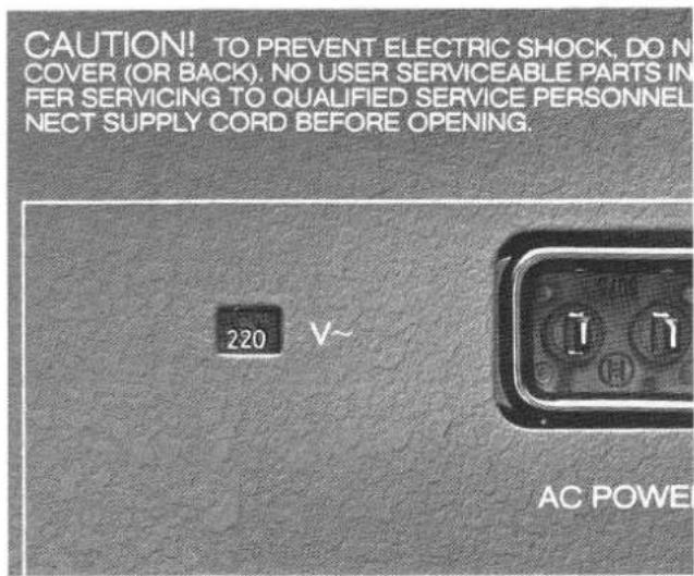
1.2.1 Checks before first time operation
Checking the line voltage:
- Does the setting of the voltage selector on the rear panel match the local line voltage?
text_image
CAUTION! TO PREVENT ELECTRIC SHOCK, DO N COVER (OR BACK), NO USER SERVICEABLE PARTS IN FER SERVICING TO QUALIFIED SERVICE PERSONNEL NECT SUPPLY CORD BEFORE OPENING. 220 V~ AC POWER- If the setting of the voltage selector must be changed it is also necessary to check the rating of the power fuse.
Fuse rates:
100V...140V=T 500mA SLOW
200V...240V = T 250mA SLOW
- The voltage selector and the fuse become accessible after the cover (four screws) has been removed. Ensure that the power cord is unplugged before you open the recorder!
- Reinstall the cover after the line voltage setting and the fuse have been checked (or replaced, if necessary).

text_image
[11] [10] [9] [8] [7] [6] [5] [4] [3] [2] [1] B 215 • CASSETTE TAPE DECK REAL TIME COUNTER PEAK PROGRAM INDICATOR REVOX INTRARED REMOTE CONTROLLED SYSTEM SET LEVEL FADE INOUT PAUSE 4/5 I/P PLAY STOP REC POWER [12] [13] [14] [15] [16] [17] [18] [19] [20] [21] [22] [23] [24] [25] [26] [27] [28] [29] [30] [31] [32] [33] [34] [35]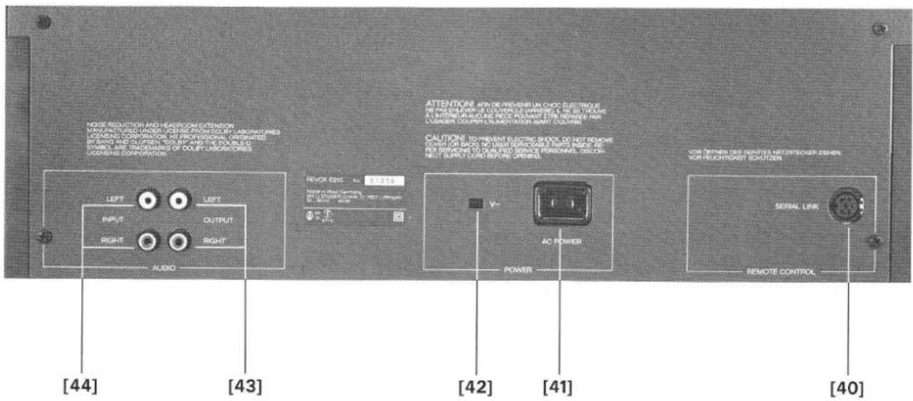
text_image
MODE REDUCTION AND HEADCOME EXTENSION MANUFACTURED UNIFIED OUTPUT FROM COLD BY LABORATORYS LOVENSING CORPORATION AT PROFESSIONAL ORGANATED BY HAND AND OLUPPEN. WELBY AND THE COOLUTS SYMBOL ARE TRANSCHANGES OF DOULY LABORATORIES LOVENSING CORPORATION [44] [43] [42] [41] [40] RETURN ON: 9.9725 RETURN ON: 9.9725 RETURN ON: 9.9725 RETURN ON: 9.9725 RETURN ON: 9.9725 RETURN ON: 9.9725 RETURN ON: 9.9725 RETURN ON: 9.9725 RETURN ON: 9.9725 RETURN ON: 9.9725 [44] [43] [42] [41] RETURN ON: 9.9725 RETURN ON: 9.9725 RETURN ON: 9.9725 RETURN ON: 9.9725 RETURN ON: 9.9725 RETURN ON: 9.9725 RETURN ON: 9.9725 RETURN ON: 9.9725 RETURN ON: 9.97251.2.2 First time operation
Check according to Section 1.2.1.
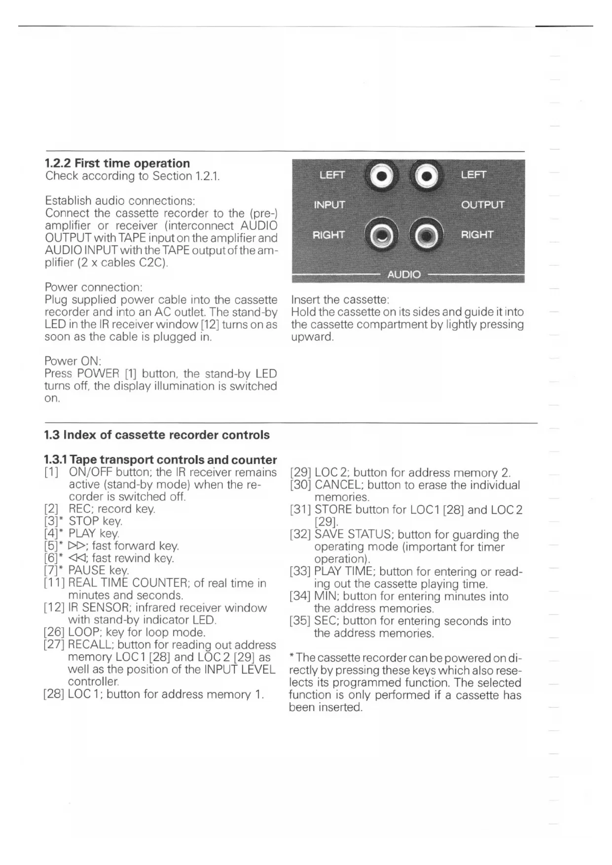
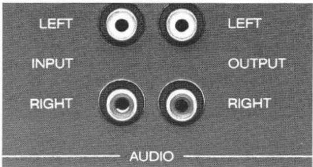
Establish audio connections:
Connect the cassette recorder to the (pre-) amplifier or receiver (interconnect AUDIO OUTPUT with TAPE input on the amplifier and AUDIO INPUT with the TAPE output of the amplifier (2 x cables C2C).
Power connection:
Plug supplied power cable into the cassette recorder and into an AC outlet. The stand-by LED in the IR receiver window [12] turns on as soon as the cable is plugged in.
Power ON:
Press POWER [1] button, the stand-by LED turns off, the display illumination is switched on.
text_image
LEFT INPUT RIGHT LEFT OUTPUT RIGHT AUDIOInsert the cassette:
Hold the cassette on its sides and guide it into the cassette compartment by lightly pressing upward.
1.3 Index of cassette recorder controls
1.3.1 Tape transport controls and counter
[1] ON/OFF button; the IR receiver remains active (stand-by mode) when the recorder is switched off.
[2] REC; record key.
[3]* STOP key.
[4]* PLAY key.
[5]* ▷; fast forward key.
[6]* ◀◀; fast rewind key.
[7]* PAUSE key.
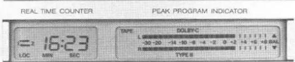
[11] REAL TIME COUNTER; of real time in minutes and seconds.
[12] IR SENSOR; infrared receiver window with stand-by indicator LED.
[26] LOOP; key for loop mode.
[27] RECALL; button for reading out address memory LOC1 [28] and LOC2 [29] as well as the position of the INPUT LEVEL controller.
[28] LOC 1; button for address memory 1.
[29] LOC 2; button for address memory 2.
[30] CANCEL; button to erase the individual memories.
[31] STORE button for LOC1 [28] and LOC2 [29].
[32] SAVE STATUS; button for guarding the operating mode (important for timer operation).
[33] PLAY TIME; button for entering or reading out the cassette playing time.
[34] MIN; button for entering minutes into the address memories.
[35] SEC; button for entering seconds into the address memories.
* The cassette recorder can be powered on directly by pressing these keys which also reselects its programmed function. The selected function is only performed if a cassette has been inserted.
1.3.2 Controls for PLAY mode
[17] TAPE TYPE; selector for manual tape type definition. Switching sequence: TYPE I (IEC I), TYPE II (IEC II, 70μs), TYPE II -120μs (IEC II, -120μs) and TYPE IV (IEC IV). The setting is shown on the display [10].
[18] NR SYSTEM; selector for noise reduction system. Switching sequence: NR system off, Dolby B on, Dolby C on, NR system off, etc.
[21] PHONES; jack socket for connecting headphones.
[22]/[23] PHONES VOLUME ±; buttons for increasing or decreasing (in steps) the volume on the headphones output.
[24] MONITOR; source/tape selector, feedback on display [10] (SOURCE or TAPE is indicated).
1.3.3 Controls for RECORD mode
[8] FADE IN/OUT; button for fading in or out during recording.
[9] SET LEVEL; button for automatic record level adjustment. Level metering is active for as long as this button is held. Level matching to the corresponding tape type takes place automatically.
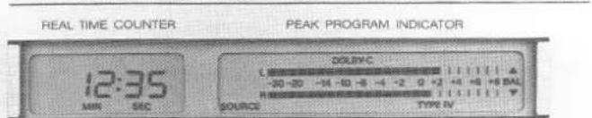
[10] PEAK PROGRAM INDICATOR; display with peak program meter and various feedback functions.
[13] INPUT LEVEL –; button to decrease the input level.
[14] INPUT LEVEL +; button to increase the input level.
[15] BALANCE L; button to shift the balance to the left.
[16] BALANCE R; button to shift the balance to the right.
[17] TAPE TYPE; selector for manual input of tape type. Switching sequence: TYPE I (IEC I), TYPE II (IEC II, 70μs), TYPE II -120μs (IEC II, -120μs) and TYPE IV (IEC IV), acknowledged in display [10].
[18] NR SYSTEM; noise reduction system selector. Switching sequence: NR system off, Dolby B on, Dolby C on, NR system off, etc.
[19] MPX; multiplex filter, can be brought into the circuit for Dolby B or C.
[20] ALIGN (calibration); button to preselect the memory location for alignment data or to start the alignment command.
[21] PHONES; jack socket for connecting headphones.
[22]/[23] PHONES VOLUME ±; buttons to increase (in steps) the volume on the headphones output.
1.3.4 Connector panel
[40] SERIAL LINK; socket for serial remote control.
[41] AC POWER; power inlet.
[42] \~ V; voltage selector window.
[43] AUDIO OUTPUT; audio signal output.
[44] AUDIO INPUT; audio signal input.
2. PLAYBACK INSTRUCTIONS
2.1 Playing a cassette
- Switch cassette recorder on by pressing the POWER [1] button.
- Hold cassette on its sides and guide it into the cassette compartment by lightly pushing it upward. If the cassette is coded according to IEC standards, the corresponding tape type is indicated on the display [10]. For cassettes that are not coded according to IEC, the standard must be entered manually by pressing the TAPE TYPE [17] button repetitively until the correct designation appears on the display [10].
- Enter the playing time of the inserted cassette by repeatedly pressing the PLAY TIME [33] button until the correct playing time appears in the display (switching sequence: C46, C60, C90, C120, C46 etc.). The playing time of the cassette must be entered to enable the real-time counter to compute the correct time in PLAY mode.
- Press PLAY [4] key. The start of a selection is indicated by rhythmic fluctuation of the bars in the PEAK READING METER (display [10]).
- The desired volume is to be set on the amplifier.
B 215 - CASSETTE TAPE DECK
text_image
REAL TIME COUNTER PEAK PROGRAM INDICATOR = 16:23 LOC MIN SEC TYPE DOLBYC -30 -20 -14 -10 -8 -4 -2 0 -2 +4 +5 +9 BAL TYPE B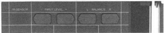
text_image
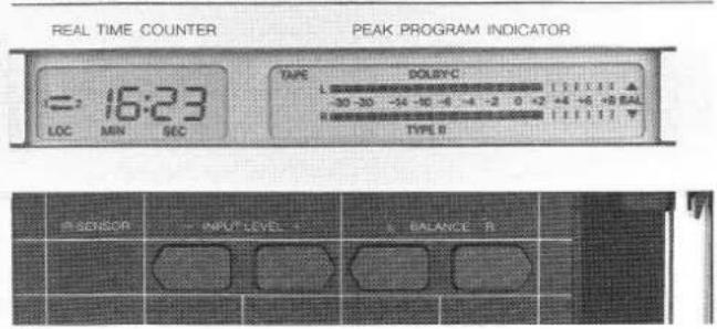
IN-SENSOR + INPUT LEVEL * L BALANCE R2.2 Playback of a Dolbyized recording
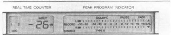
- Switch the NR SYSTEM on in addition to the normal playback preparation. Repeatedly press the NR SYSTEM [18] button until the corresponding symbol (Dolby B or C) appears in the display [10]. The Dolby level (200 nWb/m) is attained at the 0 dB mark of the PPM instrument.
- The noise reduction system can be switched off by pressing button [18] until no Dolby symbol is visible on the display.
B 215 · CASSETTE TAPE DECK
text_image
REAL TIME COUNTER PEAK PROGRAM INDICATOR 12:35 MIN SEC DOLYC L -30-20 -14 -10 -6 -4 -2 0 +2 +4 +6 +8 BAL R SOURCE TYPE IV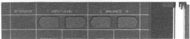
text_image
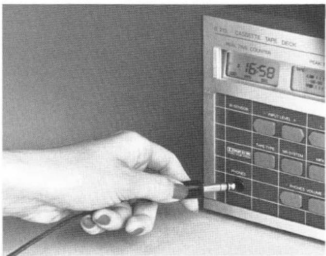
R SENSOR - RIGHT LEVEL - L BALANCE R2.3 Playback via headphones
- Connect headphones to the jack socket PHONES [21].
- The desired volume can be adjusted with the buttons VOLUME - [22] and VOLUME + [23]. The volume can get changed in 8 steps. The last step switches off the sound.
text_image
R 201 CASSSETTE TAPE DECK MAX. TIME COUNTER 16:58 R 201 TIME VOUT LEVEL TURBURE OFF POT WIRE SIGHT MOUNT POT WIRE SIGHT VOLUME2.4 Tape transport commands
- The tape can be spooled forward with the key ▷▶ [5] or backward with the key ◀◀ [6].
- An exact tape location can be found by holding down the STOP key [3] while inching the tape forward or backward by touching the corresponding spooling key [5] or [6]).
text_image
REVOX NEWARD REMOTE CONTROLLED SYSTEM OFF LINE FIRE HOUR VALUE OK ID PLAY STOP REC POWER NO FLOW NO METAL PANEL- If the tape is rewound to the start, the real-time counter accuracy and, therefore, the repeatability is very high. Any tape location can be traced with high precision. However, this is only valid if the entered cassette playing time corresponds to the utilized cassette.
- If a non-rewound cassette is inserted, the momentary counter reading is computed after a few seconds of playing time and the current tape location is indicated in the display [11] (however, the repeatability of the real-time counter is not as accurate as in the above mentioned method in which the cassette is first rewound to the start).
Note:
The cassette recorder automatically switches to STOP as soon as the tape end is reached. The transparent leader tape is recognized by an optical tape sensor. After fast rewind (key ◀◀[6]) has been pressed, the recorder automatically searches the tape start (the counter is reset to zero). The transport command keys can be pressed in any sequence without passing via STOP.
Attention:
The recording mode always erases both channels. By mono recordings the unused track is also erased. It is, therefore, recommended to make mono recordings on both channels.
The REVOX B215 cassette recorder can automatically align itself to any type of tape. Various memory locations are available for individual cassette data. Memory loading and read out are explained at the end of this Section.
3.1 Preparations for recording
- Insert cassette.
- Select tape type and playing time (buttons [17] and [33]).
IEC I = TYPE I = Fe2 O3 (ferric oxide)
IEC II = TYPE II = CrO2 (chromium dioxide, equalization 70μs)
IEC II -120μs = TYPE II -120μs = CrO₂ (chromium dioxide, equalization 120μs)
IEC IV = TYPE IV = metal pigment (metal tape)
For most cassettes the standard is automatically set based on the cassette coding and also shown in the display [10]. Cassette coding:
IEC I

IEC II

IEC IV

- If the noise reduction system is to be activated for a recording, it can be inserted by pressing the button NR SYSTEM [18]. Repeatedly press this button until the desired symbol appears on the display [10] (for a detailed description of the NR system refer to Section 3.3).
3.1.1 Setting the record level with button SET LEVEL [9]
- The record level can be automatically set by pressing the SET LEVEL [9] button while playing the loudest passage of the title to be recorded.
- The maximum level is stored after releasing the button. The characteristics of the inserted cassette are also taken into consideration.
- Occuring balance errors can be corrected with the buttons BALANCE L [15] and R [16].
- The unit is now ready for recording.
3.1.2 Manual setting/influencing of record level
It is, of course, possible to set the record level manually. This is an advantage for numerous applications (e.g. if the general dynamic range is exceeded by only a brief passage, the level can be slightly reduced during recording of this part).
B 215 · CASSETTE TAPE DECK
text_image
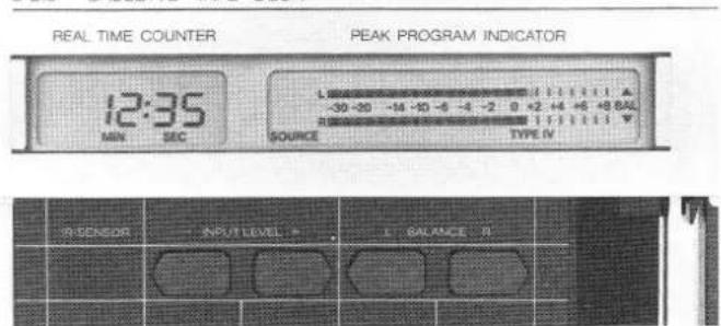
REAL TIME COUNTER PEAK PROGRAM INDICATOR 12:35 MIN SEC SOURCE TYPE IV R SENSOR INPUT LEVEL > BALANCE R- Play the title to be recorded (or similar one) and set the level according to one of the following maximum values on the PPM meter [10], depending on the tape brand:
$$ \mathrm{IEC} \quad = + 6 \mathrm{dB} $$
$$ I E C \quad I I = + 4 d B $$
$$ I E C I V = + 6 d B $$
The level can be temporarily changed during recording as follows:
- Adjust the level stepwise by repeated pressing of the buttons INPUT LEVEL - [13] or + [14] until the desired level is reached.
- The initial record level can be obtained the same way. The new level setting is shown on the display [11] each time the button is pressed.
- The set level can be displayed any time without influencing the setting by pressing first the RECALL [27] and then one of the INPUT LEVEL buttons [13]/[14].
3.2 Recording procedure
A recording can be started directly or with fade-in.
3.2.1 Recording from STOP mode
- A recording can be started out of stop mode by concurrently pressing REC [2] and PLAY [4]. (Press REC key first, otherwise the tape starts in PLAY mode, which causes erase gaps when rerecording cassettes.)
- The cassette recorder automatically switches to tape mode (reproduction of recorded signal from tape). If the source is to be monitored, the MONITOR [24] button must be pressed (the display indication [10] changes from TAPE to SOURCE).
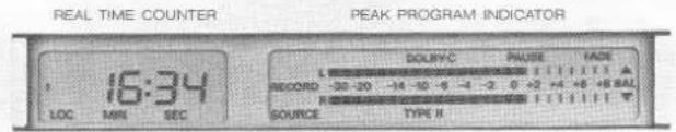
Recording mode is displayed [10] by flashing of the message RECORD.
B 215 - CASSETTE TAPE DECK
text_image
REAL TIME COUNTER PEAK PROGRAM INDICATOR 16:34 LOC MIN SEC DOLYC PAUSE FADE RECORD -20-20 -14-10-9 -4-2 0+2+4+5+6+7+8 SOURCE TYPE R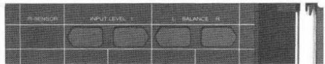
text_image
R-SENSOR INPUT LEVEL 1 L-BALANCE RImportant:
The initial tape address is stored in the LOC1 memory whenever a recording is started. When interrupting a recording by pressing the STOP key, the starting position can be relocated by pressing button LOC1 [28]. When rerecording a cassette, a small section of the previous recording might not be erased at the start. This can be prevented by holding down key ◀[6] during rewind. In this case the recorder stops when the transparent leader is reached without repositioning itself to the tape start and without resetting the timer indication. On already rewound cassettes, the tape can be backed up to the leader by briefly pressing the key ◀[6].
3.2.2 Recording from PAUSE mode
There are two reasons why it may be desirable to start a recording from PAUSE mode. First, such a recording can be prepared and started by pressing only one key, and second, it is possible on the B215 to select the FADE IN/OUT function in addition to PAUSE.
A Recording with fade in/out
- Preselect the recording function by pressing REC [2] and PAUSE [7]. PAUSE and FADE appear on the display and the MONITOR function changes to SOURCE.
B 215 · CASSETTE TAPE DECK
text_image
REAL TIME COUNTER PEAK PROGRAM INDICATOR INPUT 1 2 -26 dB LOC DOLEY-C PAUSE FADE L 00 1 2 3 4 5 6 7 8 9 10 11 12 13 14 15 16 17 18 19 20 21 22 23 24 25 26 27 28 29 30 31 32 33 34 35 36 37 38 39 40 41 42 43 44 45 46 47 48 49 50 RECORD -30-20 +30 -3 -4 -2.0 +2 +4 +6 +8 BAL R:00000000000000000000000000000000000000000000000000000000000000000000000000 SOURCE TYPE S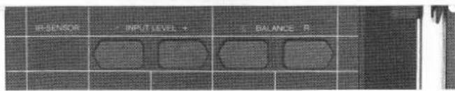
text_image
RESENSOR INPUT LEVEL 4 BALANCE R- Press the PAUSE [7] key and at that moment the fade-in starts. The recorder automatically fades in the recording. The monitor function changes to TAPE.
- To fade out of the recording press PAUSE [7] again. The recorder switches to PAUSE mode two seconds later (MONITOR = SOURCE).
- The recording can also be ended without FADE-OUT by pressing the STOP [3] key. This resets the recorder to STOP, REC and PAUSE must be reentered for a new recording.
- For fade-out without stopping the tape, press the FADE IN/OUT [8] button. After fade-out the tape continues to run, i.e. erasing continues. Fade-in can be reactivated by pressing the button [8] again. In this case, the source/tape monitor switch remains unchanged.
B Normal recording start from PAUSE mode
- Press REC [2] and PAUSE [7].
- FADE appears on the display [10] in addition to PAUSE. Since FADE is not desired, cancel by pressing the FADE IN/OUT [8] button.
- The recording starts by pressing the Pause [7] button.
- The recording can be faded out by pressing PAUSE [7]. If no fade-out is desired, the recording can be ended by pressing the STOP key.
3.3 Which noise reduction system?
The choice of the noise reduction system is very simple: For all new recordings use Dolby C. Its signal-to-noise ratio is much better than with Dolby B. Dolby B should be used only when playing existing recordings and when appending new recordings to cassettes already recorded with Dolby B. Dolby C recorded cassettes may be played back with a minor audio quality
loss in recorders equipped with Dolby B only (e.g. by car cassette players: noisier, frequency response error).
3.4 Automatic alignment
The REVOX B215 cassette recorder is able to align itself optimally to the type of tape used. Since tape-related data are automatically stored and retrievable as required, it is recommended to perform the alignment procedure for the brand of tape used. The following memory locations are available for the various tape types:
IEC I 2 memory locations A1 and A2
IEC II 3 memory locations A1, A2, and A3
IEC IV 1 memory locations A1
Alignment
- Insert cassette.
- If the inserted cassette is not coded according to IEC (refer to Section 3.1), the corresponding standard can be selected by pressing the TAPE TYPE [17] button.
- Select the memory location in which the cassette data are to be stored by pressing ALIGN [20] (appears in the display [11]).
- Prepare the RECORD mode (press REC [2] and PAUSE [7]).
- Press ALIGN [20] button, the alignment process starts. The
text_image
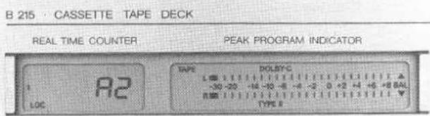
B 215 · CASSETTE TAPE DECK REAL TIME COUNTER PEAK PROGRAM INDICATOR LOC R2 TYPE DOLSYC -30 -20 -14 -10 -8 -6 -4 -2 0 +2 +4 +6 +8 BAL TYPE II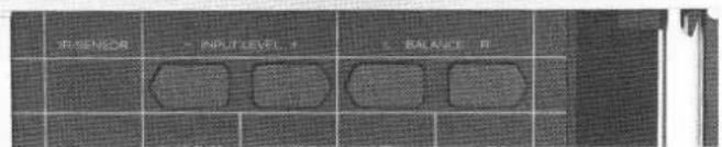
text_image
IN SENSOR + IN LUT LEVEL + - BALANCE P1tape is automatically rewound to the start position upon completion to the alignment, and the corresponding tape data are written into the selected memory.
- Since alignment is necessary only once for each cassette type, the corresponding memory location should be remembered. The alignment is only useful if the corresponding alignment data related to the cassette type are recalled.
Note:
Alignment should not be made at the very start of a tape because some tapes have damaged magnetic coating just after the leader tape. If for any reason the recorder is unable to perform the alignment, it is indicated by the flashing word ALIGN on the display [10]. In this case, the recorder is blocked until a tape command is entered as an acknowledgment. The previously stored alignment data will then remain available. For subsequent recordings, always use the same noise reduction system during the alignment (compensation for the Dolby circuit). For poor or damaged cassettes, alignment should be performed without noise reduction system.
Possible trouble sources:
- Cassette tape on transparent leader
- Wrong tape category selected
- Dirty soundheads
- Defective tape
Recall of alignment data:
- When changing to a different type of tape, the corresponding alignment data should be recalled.
- Check whether the correct cassette type is indicated on the display [10], otherwise it should be selected with the TAPE TYPE [17] button.
- Press ALIGN button repetitively until the memory location containing the corresponding alignment data is shown on the display [114]. By following this procedure, the cassette recorder is always optimally calibrated for recordings.
4. REAL-TIME COUNTER AND LOCATOR FUNCTIONS
4.1 Real-time counter
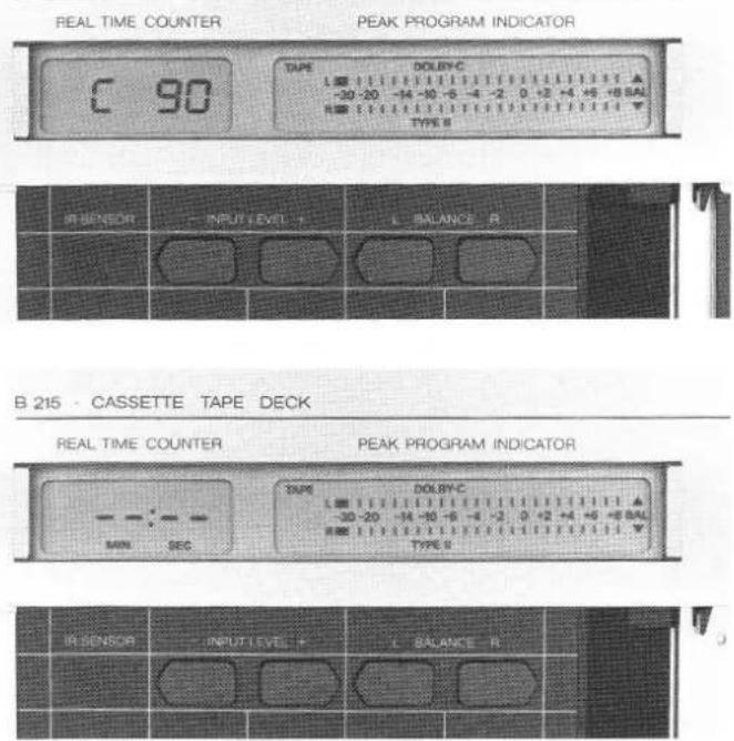
The real-time counter always displays the playing time that has elapsed since the start of the tape. It is, therefore, possible to memorize the time of a tape location and to subsequently reposition the tape at this location. The tape counter is also able to compute the current tape location of a newly inserted cassette that has not been rewound to the start in PLAY mode. It is essential, however, that the correct total cassette playing time has been entered (by pressing the PLAY TIME [33] button). The computation will be incorrect if a wrong playing time is selected.
The counter read-out is reset each time a new cassette is inserted (display [11] shows: --:--).
If this sign is displayed when a cassette is inserted this means that the counter reading has not been computed yet. However, this is done automatically when the recorder is started in PLAY or RECORD mode. The computation takes approximately 5 to 8 seconds. During the computation time the selected total cassette playing time is shown on the display [11] for verification.
B 215 CASSETTE TAPE DECK
text_image
REAL TIME COUNTER PEAK PROGRAM INDICATOR C 90 TAPE DOLBY-C -30 -20 -14 -10 -6 -4 -2.0 +2 +4 +5 +8 BAL TYPE B IR SENSOR INPUT LEVEL L BALANCE R B 215 · CASSETTE TAPE DECK REAL TIME COUNTER PEAK PROGRAM INDICATOR MIN SEC TYPE DOLBY-C -30 -20 -14 -10 -6 -4 -2.0 +2 +4 +5 +8 BAL TYPE B IR SENSOR INPUT LEVEL L BALANCE R4.2 Locator functions
Any address stored in the LOC1 or LOC2 address memories can be located from any operating mode (except RECORD) by spooling. This can be particularly useful for recordings that have to be repeated (fast search of the starting position), or for learning purposes if the same part has to be replayed several times.
4.2.1 Entering the locator address
Once the cassette has been inserted and the real time computed, the address memories LOC1 and LOC2 can be loaded in two ways.
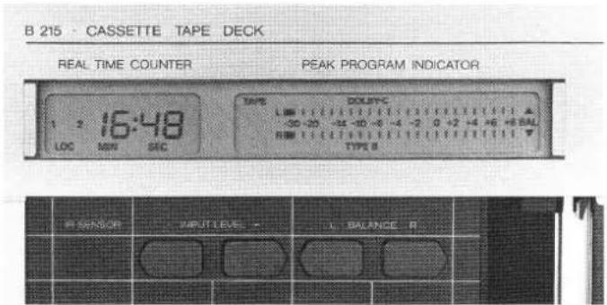
A Storing current tape location
- Search desired tape location by pressing the keys ◀◀[6].▶▶ [5], and PLAY [4].
- Store this location by pressing the STORE [31] button and LOC1 [28] or LOC2 [29] (the latter is for a second address).
The stored tape location can now be searched directly at any time regardless of the operating made (except RECORD) or the
text_image
B 215 - CASSETTE TAPE DECK REAL TIME COUNTER PEAK PROGRAM INDICATOR 1 2 16:48 LOC MEN SIC TYPE COLTYPE L 0 1 2 3 4 5 6 7 8 9 10 11 12 13 14 15 16 17 18 19 20 -30 -20 -14 -10 -8 -4 -2 0 +2 -4 +6 +8 BAL R NM 1 2 3 4 5 6 7 8 9 10 TYPE BSENSOR
INPUT LEVEL
BALANCE R
current counter reading, by pressing the LOC1 [28] or LOC2 [29] button.
B Direct input of an address (numeric)
The LOC1 and LOC2 address can also be entered directly through the buttons MIN [34] and SEC [35] without interfering with the currently active mode.
- The minutes can be entered by repetitive pressing or holding down of the MIN [34] button and the seconds with the SEC [35] button.
- When the desired position is shown in the display [11] it can be stored by pressing the STORE [31] button followed by the corresponding LOC button.
The current counter reading reappears on the display [11] after the LOC address has been stored.
4.2.2 Reading out the address memory contents
If a value is stored in the address memory, this is indicated in the display [11] (word LOC and above number 1 and/or 2).
Pressing the RECALL [27] button followed by one of the LOC buttons reads out the stored address on the display [11] without interfering with the current operating mode.
4.2.3 Erasing the content of a LOC memory
The content of the corresponding LOC memory is erased by pressing the CANCEL [30] button followed by one of the LOC buttons.
4.3 Loop (repeat) mode
If both address memories have been entered, the recorder can be switched to repeat or loop mode by pressing the LOOP [26] button.
Cancel the LOOP function by selecting one of the transport commands.
During LOOP mode, the loop can be restarted at any time by pressing the LOOP [26] button again. It is not possible to erase the content of one of the address memories while the loop mode is active.
Note:
LOOP-Function is cancelled as soon as leader-tape is reached after automatic rewinding in LOOP-Function.
This can be avoided by setting the start address one minute after tape start.
B 215 · CASSETTE TAPE DECK
text_image
REAL TIME COUNTER PEAK PROGRAM INDICATOR = 16:23 LOC MIN SEC TAPE DOLBYC -30 -30 -34 -36 -4 -2 0 +2 +4 +6 +8 RAL TYPE B P-SENSOR INPUT LEVEL BALANCE R5. REMOTE CONTROL
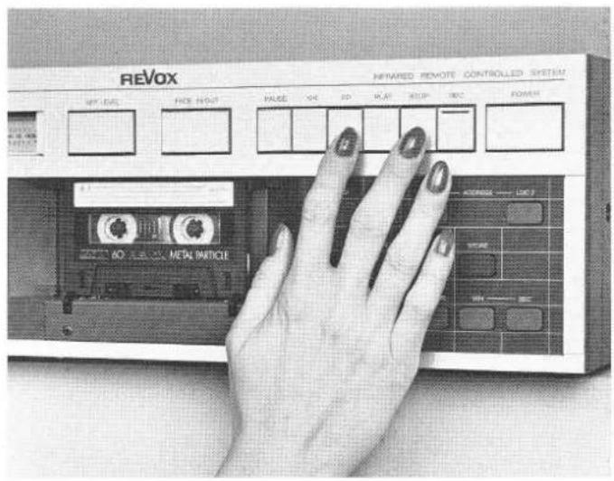
5.1 Remote control with hand-held infrared transmitter
The cassette recorder can be controlled with the REVOX infrared remote control (B201, B201 CD or B205).
The buttons that control the B215 cassette recorder are located in the lower field of the hand-held IR transmitter. The following functions can be controlled: PLAY, REC, (and PAUSE), ◀◀ and ▶▶, STOP, POWER OFF, and MONITOR.
The illustration shows that the keys are labeled in exactly the same way as on the recorder itself.
The * button is used to control a second tape recorder by means of the same remote control. (For the 2nd recorder, each function must be selected together with the * button.)
5.2 Defining the address
The cassette recorder is originally set for direct control. Which device is to be controlled via the * button depends on the extent of its utilization, i.e. the less frequently used recorder should be controlled via the * button.
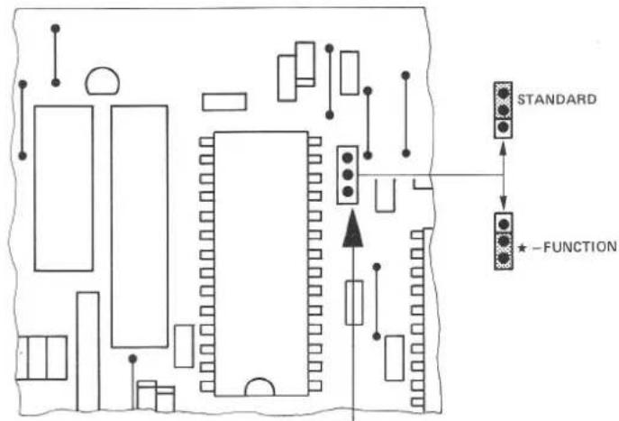
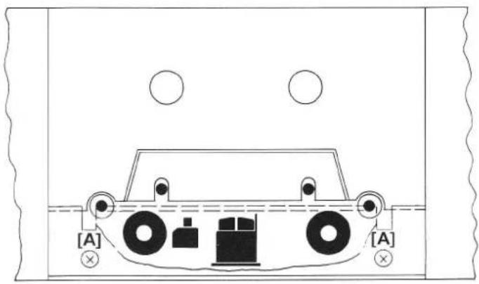
Changing the address:
- Disconnect the recorder from the AC supply and remove the cover (also refer to Section 1.2.1).
- Replug the jumper [A] according to the desired address as follows:
text_image
STANDARD -FUNCTION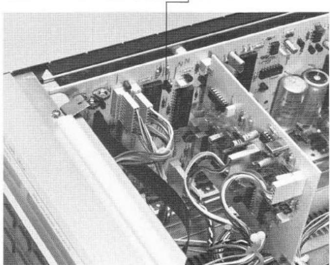
natural_image
Interior view of an electronic device with visible circuitry and components (no text or symbols)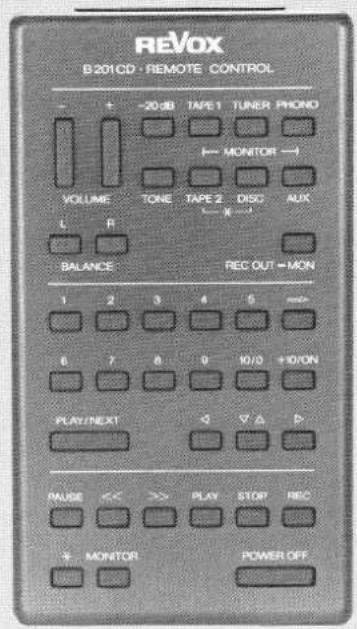
text_image
REVOX B201CD · REMOTE CONTROL - + -20 dB TAPE 1 TUNER PHONO VOLUME TONE TAPE 2 DISC AUX L R BALANCE REC OUT = MON 1 2 3 4 5 mm+ 6 7 8 9 IO/3 + IO/ON PLAY/NEXT ▼ ▼ ▶ PAUSE << >> PLAY STOP REC + MONITOR POWER OFF5.3 SERIAL LINK socket
Facility to connect a bidirectional serial cable remote control (for tape transport functions, LOC addresses, feedback of counter reading, etc.) or an external IR receiver (installed in an adjacent room).
Serial Link
1 = GND
2 = GND (floating)
3 = serial I/O
4 = +5 V floating
5 = +5 V 150 mA max.
6 = n.c.
6. TIMER OPERATION
Timer operation is possible with any commercially available timer.
6.1 Preparations for timer operation
- Switch on the recorder and select desired mode (recording with REC and PAUSE, playback with PLAY).
- All recorder settings (such as record level, NR system, balance, etc.) can be stored in a nonvolatile memory by pressing the SAVE STATUS [32] button.
- Disconnect recorder from the AC supply and reconnect it via a commercially available timer (can also be installed before).
- Set the timer to the desired power-on time.
Note:
The SAVE STATUS function can also be useful in the event of a power failure. The function is automatically reactivated after a power failure, if the operating parameters have been stored by pressing the SAVE STATUS [32] button. However, recording mode is only reactivated after the first restoration of supply. After a second power failure the recorder is reactivated in STOP mode (protects against unwanted recording). For PLAY mode, several off/on cycles are possible. If no start in PLAY mode is desired, store the STOP function.
7. TECHNICAL APPENDIX
7.1 Maintenance of the cassette tape transport
Maintenance of the B215 cassette recorder is limited to cleaning the capstan shafts, pinch rollers, soundheads with their tape guide elements, and to occasional demagnetization of the metal parts that come in contact with the tape.
The cleaning kit No. 39000 is suited for this purpose. In the case of very dirty tape guide elements, remove the headshield as illustrated. (Picture shows the locations to be cleaned.)
The tape transport can also be cleaned with commercially available cleaning and demagnetizing cassettes.
text_image
[A] [A]7.2 Equalization 120μs for IEC II cassettes
The unusual equalization for chromium dioxide cassettes has been chosen because this type of tape material is frequently used for prerecorded music cassettes. This improves the treble response, albeit at the expense of a slightly higher tape noise. To record this chromium dioxide tape, select the standard TYPE II-120 s.
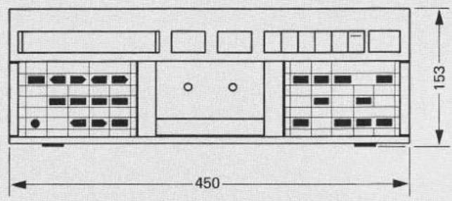
7.3 Dimensions (mm)
text_image
450 153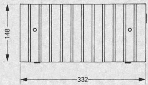
text_image
148 332
natural_image
Pure electrical circuit lines without any symbols7.4 Technical data
| Transport mechanism: | 4-motor tape drive.2 DC spooling motors controlled by microcomputer, 2 individually controlled direct drive capstan motors. |
| Tape counter: | real-time display in min./sec., in consideration of the preselected cassette playing time. |
| Locator functions: | 2 arbitrary addresses storable and erasable, possibility for loop (repeat) mode. |
| Tape speed: | 4.76 cm/s (17/8 ips) |
| Wow and flutter:(DIN 45507 / IEC 386) | 0.1% with C60 and C90 cassettes |
| Useable cassettes: | C46 to C120 (specified data guaranteed up to C90 only) |
| Winding times: | approx. 50 sec. for C60approx. 75 sec. for C90 |
| Noise reduction systems: | Dolby B / Dolby C processors, switch-selectable, in the recording and reproducing channels. |
| Tape selection: | type I = Fe_2O_3 (2 memory locations: A1, A2)type II = CrO_2 (3 memory locations: A1, A2, A3)type IV = Metal (1 memory location: A1)selection by automatic sensing of coded cassettes or manually via keyboard. |
| Playback equalization: | type I 3180 + 120 μstype II 3180 + 70 μs or 120 μstype IV 3180 + 70 μs |
| Peak level meter: | 200 nWb/m equals 0 dB |
| Distortion:(HD3, 315 Hz, 0 dB) | type I <0.8 %type II <1.5 %type IV <1.0 % |
| Frequency response:(via tape, after automatic alignment) | type I : 30 Hz...18 kHz +2/-3 dBtype II : 30 Hz...20 kHz +2/-3 dBtype IV : 30 Hz...20 kHz +2/-3 dB |
| Signal to noise ratio: referred to 3% distortion, Dolby C on | type I >70 dB(A) type II >72 dB(A) type IV >72 dB(A) |
| Separation: | >40 dB at 1 kHz |
| Bias and erase frequency: | 105 kHz |
| Erase efficiency: | >70 dB at 1 kHz, Dolby C on |
| Input sensitivity: (for 0 dB level) | 50 mV / 100 kOhms; level adjustable in 60 steps, max. resolution = 1 dB |
| Max. admissible input voltage: | 2.5 V |
| Outputs: (referred to 200 nWb/m) | LINE OUTPUT: 0.775 V / R_j = 1.5 kOhms PHONES: max. 2.8 V / R_j = 220 Ohms level adjustable in 7 steps |
| Voltage selector: | 100/120/140/200/220/240V AC selectable, ±10%, 50...60 Hz, max. 45 W |
| Fuse: | 100 ... 140 V : T 500 mA SLOW 200 ... 240 V : T 250 mA SLOW |
| Operating conditions: | ambient temperature +5 ... +40°C (+41 ... +104°F) relative humidity according to DIN 40040, class F |
| Operating position: | only horizontal (cassette vertical) |
| Weight: | 9.150 kg (20 lbs 3 ozs) |
| Dimensions: | (W x H x D) 450 x153 x 332 mm (17.7 x 6 x 13.1 inches) |
The tape-specific measured values are attained with modern high quality cassettes.
Noise reduction and headroom extension manufactured under license from Dolby Laboratories Licensing Corporation. HX Professional originated by Bang and Olufsen, "Dolby" and the double-D symbol are trade marks of Dolby Laboratories Licensing Corporation.
Subject to change.
MODE D'EMPLOI
text_image
[11] [10] [9] [8] [7] [6] [5] [4] [3] [2] [1] B 215 • CASSETTE TAPE DECK REAL TIME COUNTER PEAK PROGRAM INDICATOR REVOX INFRARED REMOTE CONTROLLED SYSTEM SET LEVEL FADE N/OUT PAURSE QD DO PLAY STOP REC POWER CORRER PRO/LEVEL BALANCE TYPE TYPE MACHINE MODE ALIEN CORRATING PUMBER PUMBER VOLUME MOUNTAIN [25] [26] [27] [28] [29] [30] [31] [32] [33] [34] [35] [12] [13] [14] [15] [16] [17] [18] [19] [20] [21] [22] [23] [24]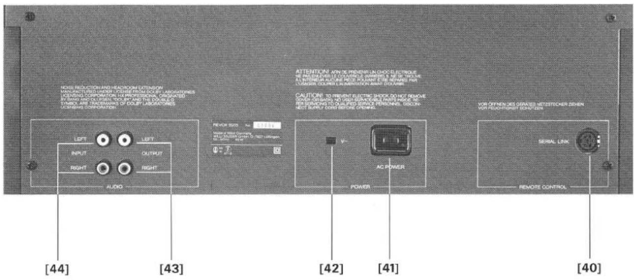
text_image
NOSI PRODUCTION AND HEADROOM EXTENSION MANUFACTURED WORKING UPSIDE RESOLUTION FOR LABORATORIES ICENSING CORPORATION, HA PROFESSIONAL, ORIGATED INVOICE AND COORDERS YOU ARE THE COURSE SYMBOL ARE TRANSFORMS OF DOLEY LABORATORIES CONSINE CORPORATION. LEFT INPUT RIGHT AUDIO LEFT OUTPUT AUDIO REVOE 500 N= 10000 AUX OF PEEF Germany ALL U.S. (24) Lower O-3mm oxygen in dBm AC POWER POWER CAUTION: TO PREVENT ELECTRIC SHOCK DO NOT REMOVE COOPERATION NO VSUS ENVOODABLE FROM MARGE AC PER SERVING TO QUALIFIED SERVICE PERSONS, DISCON- NOT SUPPLY CORE BEFORE OPENING. VOR OFFEN DES GERATES NETESTECHER SEHEN VOR PEUCH-POSET HIGH CEN. SERIAL LINK REMOTE CONTROL [40] [41] [42] [43] [44]text_image
FLOOR NEE LEASE BLANCE 2text_image
IEC I IEC II IEC IVtext_image
REAL TIME COUNTER PEAK PROGRAM INDICATOR 12:35 MIN SEC SOURCE TYPE IVSENSOR INPUT LEVEL → BALANCE R
$$ I E C \parallel = + 4 d B $$
$$ \mathrm{IEC} \quad \mathrm{IV} = + 6 \mathrm{dB} $$
text_image
SENSOR INPUT LEVEL 1 L BALANCE RImportant :
text_image
R-SENSOR - INPUT LEVEL R L-BALANCE RIEC IV 1 emplacement mémoire A1
Calibrage :
text_image
REAL TIME COUNTER PEAK PROGRAM INDICATOR = 16:23 LOC MIN SEC TAPE DOLBYC -20 -20 -14 -10 -8 -6 -4 -2 0 +2 +4 +6 +8 BAL TYPE 9 R SENSOR INPUT LEVEL L BALANCE R5. TÉLÉCOMMANDES
text_image
Normal Adresse *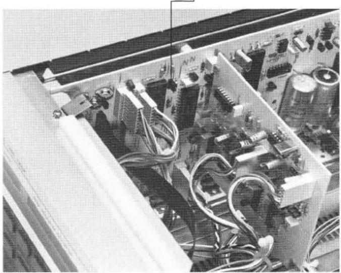
natural_image
Interior view of an electronic device with visible circuitry and components (no readable text or symbols)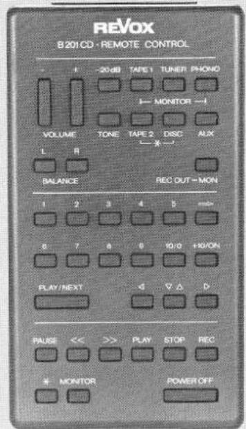
text_image
REVOX B201CD · REMOTE CONTROL - - 20 dB TAPE 1 TUNER PHOIO MONITOR -1 VOLUME TONE TAPE 2 DISC AUX L R BALANCE REC OUT-MON 1 2 3 4 5 # 8 7 8 9 10/10 +10/ON PLAY/NEXT ◀ ▼ △ D PAUSE << >> PLAY STOP REC * MONITOR POWER OFF5.3 Raccordement SERIAL LINK
1 = GND
2 = GND (floating)
3 = serial I/O
4 = +5 V floating
5 = +5 V 150 mA max.
6 = n.c.
6. FONCTIONNEMENT AVEC UNE MINUTERIE
natural_image
Pure diagram of a rectangular panel with vertical lines and a bottom line, no text or symbols present.Noise reduction and headroom extension manufactured under license from Dolby Laboratories Licensing Corporation. HX Professional originated by Bang and Olufsen, "Dolby" and the double-D symbol are trade marks of Dolby Laboratories Licensing Corporation.