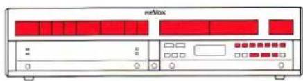
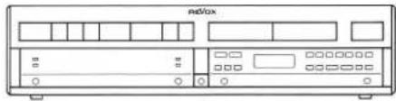
B250 - Audio Receiver REVOX - Free user manual and instructions
Find the device manual for free B250 REVOX in PDF.
| Product type | Audio receiver / integrated amplifier |
| Brand | Revox |
| Model | B250 |
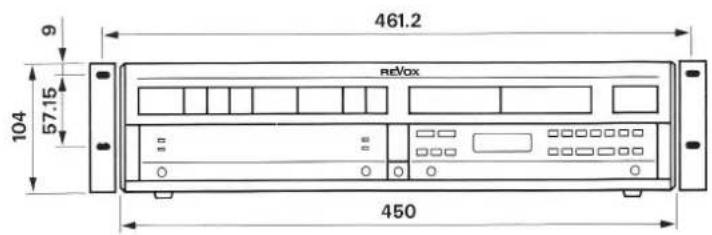
| Dimensions (W x H x D) | 450 x 109 x 332 mm |
| Weight | approx. 15 kg |
| Mains power supply | 100–240 V AC, +5%/-10%, 50–60 Hz (internally switchable) |
| Maximum power consumption | 800 W |
| Standby power consumption | approx. 10 W |
| Sinusoidal power (DIN 45500) | 2 x 200 W at 4 Ω, 2 x 120 W at 8 Ω |
| Maximum power (1 kHz, 1 period) | 2 x 300 W at 4 Ω, 2 x 160 W at 8 Ω |
| Damping factor | ≥ 100 (1 kHz, 8 Ω) |
| Harmonic distortion | ≤ 0.006% (1 kHz, 180 W, 4 Ω) |
| Signal-to-noise ratio (TUNER, etc.) | 98 dB (200 W, 4 Ω, 1 kΩ terminated) |
| Inputs | TUNER, CD, AUX, TAPE 1, TAPE 2, PHONO MM/MC (option), PWR-AMP |
| Outputs | SPEAKERS A/B, PRE-AMP, PHONES, TAPE 1/2, RECORD, MONITOR |
| Tone controls | BASS ±12 dB (40 Hz), TREBLE ±12 dB (14 kHz), stepped |
| Special features | Preamp/power amp separation, LOUDNESS, -20 dB, MAX VOLUME, SENSITIVITY, REC-OUT/REC=IN |
| Remote control | IR REVOX B208 (optional) |
| Protection | Thermal protection, overload, short circuit, microprocessor RESET |
| Speaker connection | Terminals for SPEAKERS A and B, impedance 4–8 Ω |
Frequently Asked Questions - B250 REVOX
User questions about B250 REVOX
0 question about this device. Answer the ones you know or ask your own.
Ask a new question about this device
Download the instructions for your Audio Receiver in PDF format for free! Find your manual B250 - REVOX and take your electronic device back in hand. On this page are published all the documents necessary for the use of your device. B250 by REVOX.
USER MANUAL B250 REVOX
Operating Instructions
Mode d'emploi
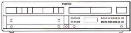
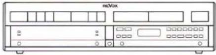
text_image
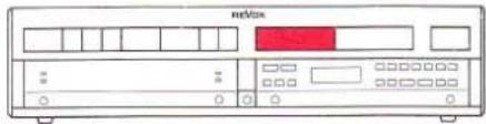
B 250-S • AMPLIFIER REVOX TUNER 1 TAPE 2 AUX CD PHOTO -20dB TV 1 VCP 2 DISC VIDEO OPEN TUNERWarning: This unit is not separated from the mains supply when switched off (STANDBY).
Subject to change. Printed in Switzerland by WILLI STUDER AG Order number 10.30.1230 (Ed. 1188) Copyright by WILLI STUDER AG CH-8105 Regensdorf-Zurich
REVOX is a registered trade mark of WILLI STUDER AG Regensdorf.
natural_image
Front view line drawing of a retrobox (no text or symbols)Packungsinhalt
natural_image
Black-and-white photo of a cardboard box, a small electronic device labeled B25G, and a plug with cable (no readable text or symbols)natural_image
Front view of a vintage audio workstation (no visible text or labels)natural_image
Back panel of a network equipment unit showing multiple ports and connectors (no visible text or labels)natural_image
Back panel of a portable electronic device showing ports, connectors, and indicator lights (no visible text or labels)text_image
rate Tape 1natural_image
Diagram of a device rear panel connected to a cable, showing ports and connectors (no text or labels)natural_image
Diagram of a device rear panel connected to a cable, showing ports and connectors (no text or labels)TAPE 1 [50], TAPE 2 [49]
![REVOX B250 - TAPE 1 [50], TAPE 2 [49] - 1](/content/2026/02/383402/images/38d3292174fecaade70753e83274885bb041d8352761449c96f16f476718046e.jpg)
text_image
0], TAPE 2 [49] Tape 2natural_image
Back panel of a computer interface showing ports, connectors, and a red indicator button (no text or symbols visible)text_image
REXO TUNIPEnatural_image
Front view of a red and white electronic device with ports and buttons (no visible text or symbols)TUNER [12], CD [8], AUX [9]
![REVOX B250 - TAPE 1 [50], TAPE 2 [49] - 2](/content/2026/02/383402/images/7ce5790151844d7700014689475c1729202eda4fde08a44df8d9e08b37bae33f.jpg)
text_image
TUNER CD AUXtext_image
TAPE 1 TAPE 2text_image
L = 200 m 100 m L = 400 m 300 m L = 800 m 500 mtext_image
L PF 450 R 50Ausnahme:
natural_image
Front view of a beige electronic device labeled 'netBox' with ports and indicator lights (no readable text beyond label)![REVOX B250 - TAPE 1 [50], TAPE 2 [49] - 3](/content/2026/02/383402/images/07e9be954d135eb48d39868d14a54a7ee9980cda149101b1d6ef714861a441a9.jpg)
![REVOX B250 - TAPE 1 [50], TAPE 2 [49] - 4](/content/2026/02/383402/images/884e21c1bb3f4b050cdbd2affbc8f0a0c4a62124f542ab08af56f40c70ab4a99.jpg)
![REVOX B250 - TAPE 1 [50], TAPE 2 [49] - 5](/content/2026/02/383402/images/cc17026b203e2380b3448161caa39d4dbb807c7d1b609e5acec884b98c25234b.jpg)
text_image
HMXnatural_image
Back panel of a network equipment unit showing ports, connectors, and a switch (no visible text or labels)natural_image
Back panel of a computer interface showing ports and connectors (no visible text or labels)natural_image
Front view of a red and white electronic device labeled 'netbox' (no readable text or symbols beyond branding)natural_image
Technical line drawing of an industrial machine with rollers and a rotating component (no text or symbols)100...140VAC: T6,3A/250V (SLOW)
200...240VAC: T3.15A/250V (SLOW)
natural_image
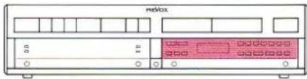
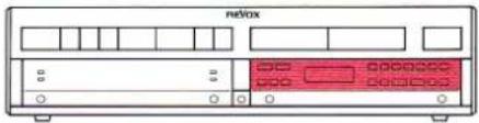
Front view of a rectangular electronic device with vertical slots and top tabs (no text or symbols)For the sake of clarity these operating instructions have been subdivided into the following 5 Sections:
SECTION 1
Installation procedure
Describes the procedures to be followed for installing the amplifier and putting it into operation.
SECTION 2
Main keypad
Explains all main functions of the amplifier.
SECTION 3
Auxiliary keypad (behind hinged cover)
Explains all auxiliary and special functions that are not covered in Section 2, such as SPEAKERS A/B, PRE-OUT, and MAX VOLUME.
SECTION 4
Technical appendix
Contains useful information concerning the operation of the amplifier, error messages and corresponding corrective action, as well as technical data and dimensions.
SECTION 5
List of keypad functions
Contains a quick-reference operating guide for experienced and professional users and a summary of all keypad functions.
Quick-reference diagram
At the end of this handbook you will find a foldout page with a quick-reference diagram on which all the operator controls are identified with an index number. These numbers agree exactly with the bracketed numbers in the text.
| Protect your amplifier from exposure to excessive heat and moisture. Install it in a position where the ventilation louvers are not obstructed. | |
| WARRANTY | A special warranty request card is included with all equipment sold within the Federal Republic of Germany. This card is located either inside the packing or in a plastic pouch attached to the outside of the packing. Should this card be missing, please consult your REVOX dealer or your national REVOX distributor.Warranty cards for equipment sold in Switzerland or Austria are issued directly by the authorized dealer.Please note that the warranty is only valid within the country in which the equipment has been sold. The warranty becomes null and void if unauthorized modifications or unprofessional repairs are made. |
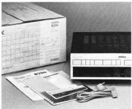
| PACKING MATERIAL | Please retain the original packing material for reuse in case your unit ever needs to be transported. The packing in which you received it has been especially designed to protect your valuable equipment from mechanical shock in transit. |
Table of contents
| SECTION 1 | Page | |
| Installation | Accessories included | 4 |
| Setting up the amplifier | 4 | |
| Safety regulations | 4 | |
| Start-up | AC Line voltage | 5 |
| Connecting the signal sources | 5 | |
| Connecting the outputs | 6 | |
| Power on | 7 | |
| SECTION 2 | ||
| Main keypad | Signal sources | 9 |
| Volume | 10 | |
| SECTION 3 | ||
| Auxiliary keypad | Hinged cover | 11 |
| Signal outputs | 11 | |
| Stereo balance | 12 | |
| Tone control | 12 | |
| Recording | 13 | |
| Phono cartridge systems (MM, MC) | 14 | |
| Separating the preamplifier/power amplifier | 15 | |
| Adjustments: | ||
| - MAX VOLUME | 16 | |
| - PWR-ON VOLUME | 17 | |
| - SENSITIVITY: SPEAKERS, PRE-OUT | 18 | |
| - SENSITIVITY: INPUT | 19 | |
| SECTION 4 | ||
| Error messages | <<<< | 21 |
| OVERLOADED!!! | 21 | |
| BREAKDOWN!!! | 21 | |
| Fault sources | Troubleshooting | 22 |
| Technical appendix | IR remote control REVOX B208 | 24 |
| AC line voltage | 26 | |
| Power fuse | 26 | |
| Technical data | 27 | |
| Dimensions | 28 | |
| SECTION 5 | ||
| List of keypad functions | Quick-reference description of all functions | 29 |
| Indexed quick-reference diagram | 32 | |
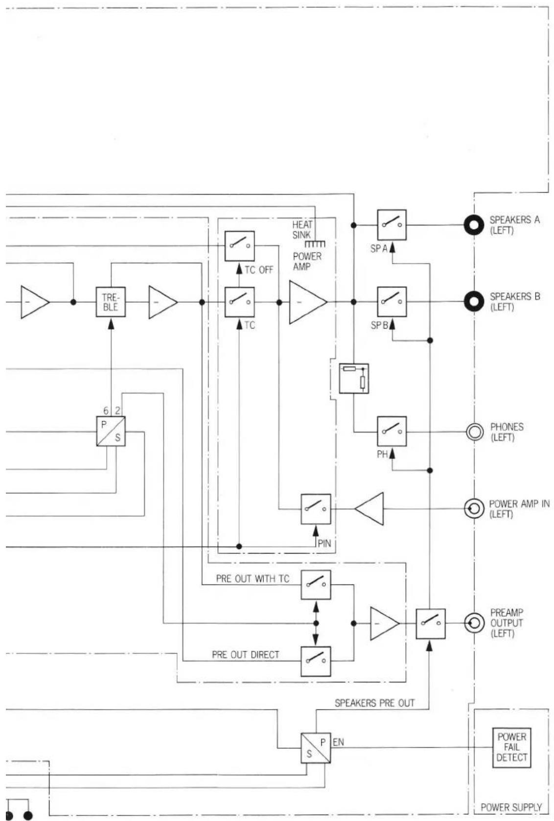
| Audio block diagram | 33 | |
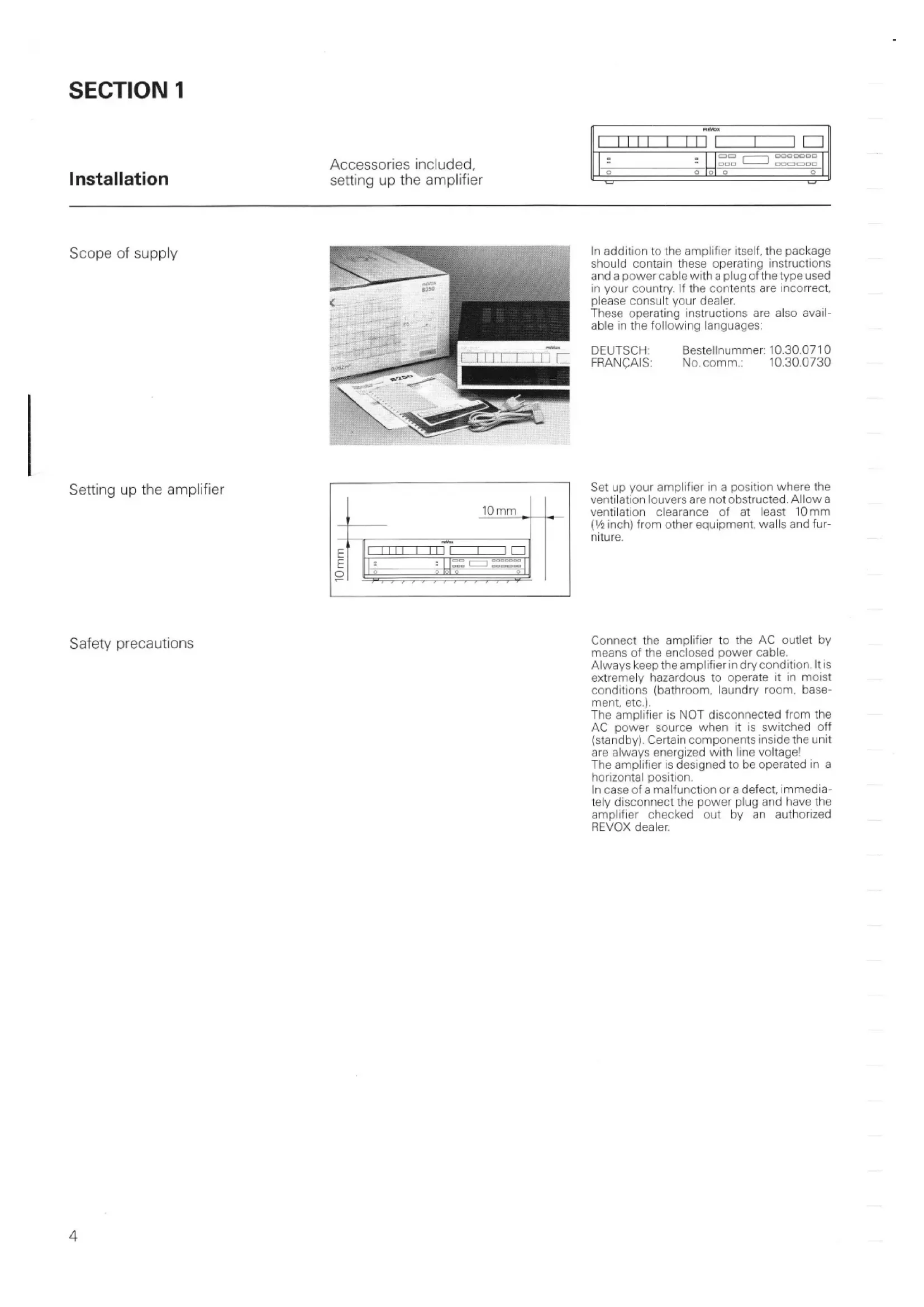
SECTION 1
Installation
Accessories included, setting up the amplifier
text_image
HDFS 3.8 1.8 0 0Scope of supply
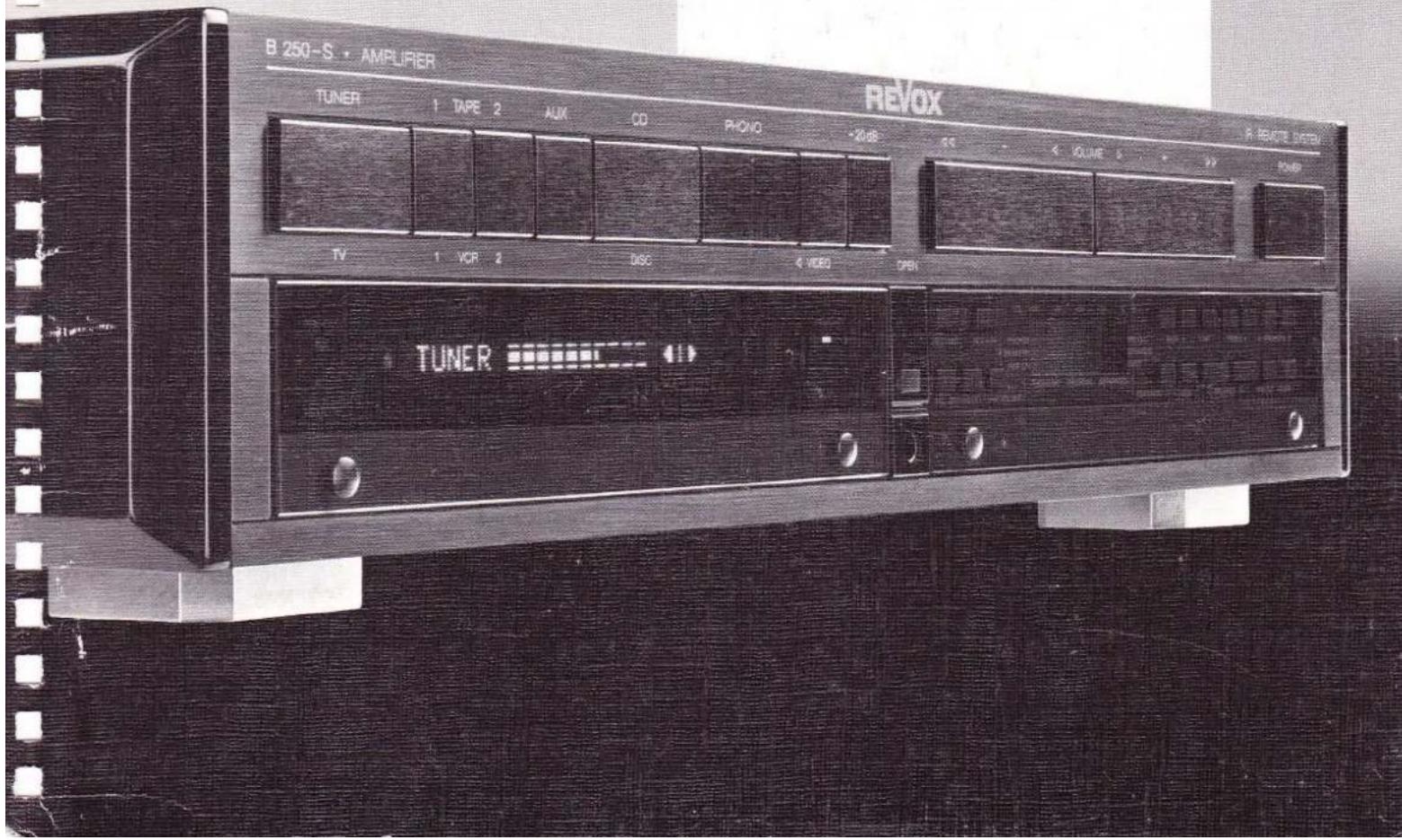
natural_image
Black-and-white photo of a cardboard box, a circuit board, and an electronic device with cables (no visible text or symbols)In addition to the amplifier itself, the package should contain these operating instructions and a power cable with a plug of the type used in your country. If the contents are incorrect, please consult your dealer.
These operating instructions are also available in the following languages:
DEUTSCH: Bestellnummer: 10.30.0710
FRANÇAIS: No. comm.: 10.30.0730
Setting up the amplifier
text_image
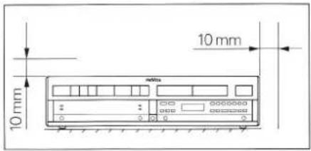
10 mm 10 mmSet up your amplifier in a position where the ventilation louvers are not obstructed. Allow a ventilation clearance of at least 10 mm ( 12 inch) from other equipment, walls and furniture.
Safety precautions
Connect the amplifier to the AC outlet by means of the enclosed power cable.
Always keep the amplifier in dry condition. It is extremely hazardous to operate it in moist conditions (bathroom, laundry room, basement, etc.).
The amplifier is NOT disconnected from the AC power source when it is switched off (standby). Certain components inside the unit are always energized with line voltage!
The amplifier is designed to be operated in a horizontal position.
In case of a malfunction or a defect, immediately disconnect the power plug and have the amplifier checked out by an authorized REVOX dealer.
Start-up
Checking the line voltage, connecting the signal source
text_image
metboxChecking the line voltage
natural_image
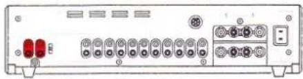
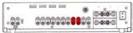
Front view of a network device rear panel with ports and connectors (no visible text or labels)Make sure that the voltage rating inscribed below the power inlet [56] agrees with your local line voltage.
The amplifier can be switched to a different line voltage but this work should be performed by your dealer.
Connecting the signal sources
natural_image
Back panel of a network device showing multiple ports and connectors (no visible text or labels)Make sure that all components to be connected to the amplifier are switched off, or even better, disconnected from the AC power source.
Connect the audio outputs (OUTPUT) of these components (signal sources) such as tuner, CD player, and tape deck to the corresponding inputs of the amplifier.
An additional CD player, a third tape recorder, or a second tuner can be connected to the auxiliary input AUX [43].
Do not confuse the channels left (L) and right (R).
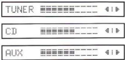
Tuner, CD, Aux
text_image
Aux CD-Player TunerConnect the outputs of a tuner (radio receiver) or CD player to the inputs TUNER [46] or CD [42].
Turntable
text_image
PhonoConnect the turntable outputs to the corresponding PHONO [38/40] inputs of your amplifier.
If your turntable is equipped with a stranded ground wire, the latter should be connected to the ground terminal [39].
Turntables with a conventional moving magnet cartridge system should be connected to the terminal marked MM [40] while those with a moving coil cartridge system should be connected to the terminal marked MC [38]. If an MC cartridge system is used the amplifier must be retrofitted with an MC preamplifier (option).
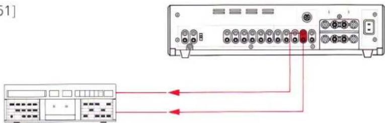
Tape recorders
text_image
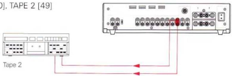
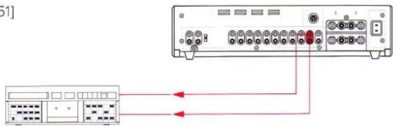
Tape 1Two tape recorders can be connected to the amplifier. Connect the tape recorder outputs to the TAPE 1 [45] and TAPE 2 [44] inputs of the amplifier.
For making recordings, the tape recorder inputs must be connected to the corresponding amplifier outputs TAPE 1 [50] and TAPE 2 [49].
natural_image
Front view of a vintage electronic device with ports and indicator lights (no visible text or symbols)Speakers
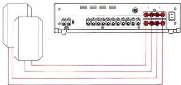
natural_image
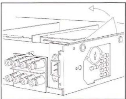
Diagram of a device rear panel connected to a cable, showing ports and connectors (no text or labels)Two speaker pairs can be connected to the goldplated speaker terminals SPEAKERS A [54] and SPEAKERS B [55] of the REVOX B250 · amplifier.
Speakers with an impedance of 4 Ohm or 8 Ohm should preferably be used.
Connect only the terminals of like color between the amplifier and the speakers (correct phasing).
The ground terminals (black terminals) of the individual speakers must not be interconnected.
In order to minimize power loss to the speakers. Use cables with a large conductor cross-section. 12 gauge wire can be easily connected to the terminals. Conventional banana plug (diam. 4 mm) can be connected directly.
Active speakers
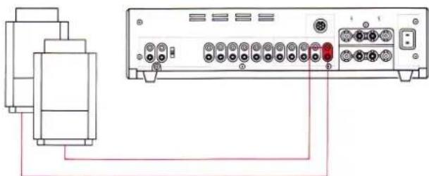
natural_image
Diagram of a device rear panel connected to a cable, showing ports and connectors (no text or labels)Active speakers (with built-in amplifiers) should be connected to the PRE-AMP [53] output of the preamplifier.
This output is activated when you press the PRE-OUT [34] key (behind the hinged cover). When connecting active speakers, limit the maximum cable length to the value recommended in the relevant operating instructions and use only well-shielded audio cables.
TAPE 1 [50], TAPE 2 [49]
![REVOX B250 - TAPE 1 [50], TAPE 2 [49] - 1](/content/2026/02/383402/images/59b7c4610458378b59ee352e06f8b9533d235fe73992bad05826376eabd29e42.jpg)
text_image
0], TAPE 2 [49] Tape 2The outputs TAPE 1 [50] and TAPE 2 [49] are reserved for the recording paths of the recorders TAPE 1 and TAPE 2. When a tape recorder operates in play mode, the record output of the corresponding unit is disabled so that TAPE COPY from one recorder to another is possible without feedback.
MONITOR [48]
![REVOX B250 - MONITOR [48] - 1](/content/2026/02/383402/images/b59b1d00deec9ac0d13465c6bef6ec6bd3790a6fabf8ae865044eb57b0f78d09.jpg)
text_image
[48]An additional tape recorder or an additional amplifier can be connected to the MONITOR [48] output. These units will not be affected by the volume, tone, and balance controls. This output always carries the signal from the source that is also audible via the amplifier outputs (SPEAKERS A/B, PREAMP).
Power Amplifier
Start-up
Connecting the signal source, power on
natural_image
Front view of a beige Max computer interface with ports and indicator lights (no readable text or symbols)RECORD [51]
text_image
Diagram showing connection between a server rack and a control panel with labeled ports and red arrows indicating data flow.Tape 3
The input of an additional tape recorder, for example, can be connected to the RECORD [51] output.
This output always carries the recording signal selected with REC-OUT [19].
Caution:
When you use this output make sure that no audio loop is created (feedback), (e.g. play TAPE 1 and simultaneously record on TAPE 1 via the RECORD output).
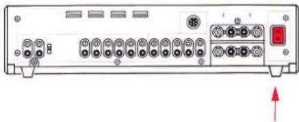
Power connection [56]
natural_image
Back panel of a computer interface showing ports, connectors, and a red indicator button (no text or symbols visible)Switching on the amplifier
text_image
netbox TUNER 41When all audio connections have been established (signal sources and speakers connected), you can connect the amplifier to an AC power outlet by means of the enclosed power cable.
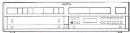
When you press the POWER [1] button on the front panel, the REVOX B250 · Amplifier switches on and the signal source that was active when the amplifier was switched off the last time is automatically selected. Pressing the POWER [1] button a second time switches the amplifier off (standby).
When the amplifier is switched off but still connected to the AC power source, it operates in standby mode which means that it can be conveniently switched on and off by means of an infrared remote control from your listening position.
The power consumption in standby is negligible (approx. 10W).
SECTION 2
Main keypad
Signal sources, volume
text_image
硬盘41XTUNER [12], CD [8], AUX [9]
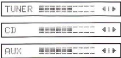
text_image
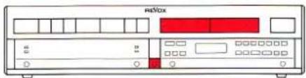
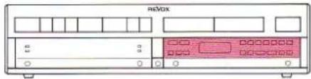
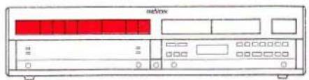
TUNER CD AUXWhen you press one of these keys the corresponding input is connected to the amplifier. The selected signal source together with the current VOLUME and BALANCE setting are indicated on the display [15]. The amplifier can also be switched on directly by selecting a signal source.
TAPE 1 [11], TAPE 2 [10]
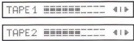
text_image
TAPE 1 TAPE 2When you press one of these keys the corresponding TAPE 1 [45] or TAPE 2 [44] input is connected to the amplifier. The selected signal source together with the current VOLUME and BALANCE setting are indicated on the display [15]. The amplifier can also be switched on directly by setting a signal source.
PHONO [7]
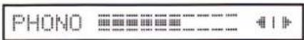
When you press one of these keys the turntable is connected to the amplifier. The selected signal source identified by the word PHONO together with the current VOLUME and BALANCE setting are indicated on the display [15]. The amplifier can also be switched on directly by selecting a signal source.
VOLUME +/- [2/3]
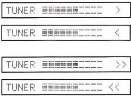
text_image
TUNER TUNER TUNER TUNERWhen you press the VOLUME + [2] key the volume increases while VOLUME - [3] decreases the volume.
The volume can be changed at two different speeds. If you press the key below the marking < and >, the volume changes slowly in small steps (1 dB). If you press the key below the markings << and >>, the volume changes rapidly in larger steps (3 dB).
The actuated VOLUME key (<,>or<<,>>) is shown on the display [15] in place of the BALANCE setting.
During the power on phase the volume can be decreased but not increased.
The maximum achievable volume depends on the MAX VOLUME set for the corresponding speaker group.
If both speaker groups are activated, the lower of the two preset maximum volumes is applicable.
- 20 dB [5]

When you press this key the volume is decreased by 20 dB in a single step. Press this key again and the volume is decreased by another 20 dB, etc. until the minimum volume is reached.
The volume can be increased by pressing the VOLUME + [2] key.
Note:
text_image
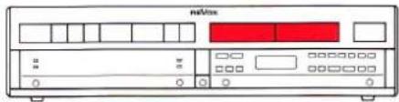
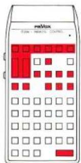
TV VCR1 VCR2 DISCYour REVOX B250 · Amplifier is equipped for future applications. In conjunction with the REVOX B200 · Controller which to can be installed below the amplifier, the VIDEO [6] key can be used to access the secondary functions TV, VCR1, VCR2, and DISC.
In this way you can connect the audio signals of a television set (TV), two video cassette recorders (VCR1, VCR2) and a DISC player to your hi-fi system. Corresponding video signals of these four sources can be connected to a monitor (television set) by means of the controller.
SECTION 3
Auxiliary keypad
Hinged cover, signal outputs
text_image
R&VXHinged cover
text_image
netboxThe tinted acrylic glass cover of the second keypad can be opened by pressing the OPEN [4] key. The LC display [24] will light up. In order to close the cover simply push it back up until it locks into place. The illumination of the display switches off. Any programming operation left incomplete in the secondary keypad will be cancelled and the previous condition reestablished.
SPEAKERS A/B [35/37]
text_image
FOXOWhen you press the SPEAKERS A [35] key the speaker group switches on or off. The SPEAKERS B [37] key controls the speaker group B. In order to prevent annoying switching clicks the microprocessor briefly switches the volume off and on again.
Both speaker groups can be switched on or off concurrently.
The green LED [17] to the right of the display [15] lights up when SPEAKERS A [54] are switched on; LED [16] indicates the state of SPEAKERS B [55].
PHONES [18]
text_image
RiBoxThe headphones can be used in any mode. Simply plug the headphones into the corresponding socket on the front panel. The volume can be controlled with the VOLUME +/- [2/3] keys.
If no speaker group is switched on, the maximum adjustable volume is determined by the MAX VOLUME set for PHONES. Otherwise the MAX VOLUME set for the activated speaker group (or the lower value if both groups are switched on) is applicable.
PRE-OUT [34]
text_image
HertzWhen you press the PRE-OUT [34] key the PRE-AMP [54] output of the amplifier is switched on or off.
As is the case for the outputs SPEAKERS A/B [54/55], the microprocessor switches the volume off for the duration of the switching process. This output can be switched independently of the two speaker groups A and B. The green LED on the left-hand side of the display [15] lights up when the preamplifier output is activated.
Auxiliary keypad
Stereo-Balance, Tone Control
text_image
nRMXBALANCE L/R [30/32]
text_image
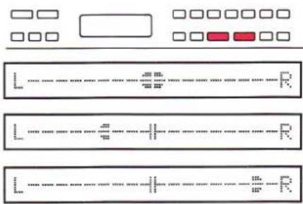
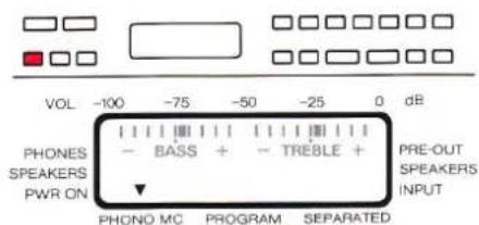
Diagram showing three labeled rectangular panels with dotted lines and checkboxes, likely representing a layout or layout design.With the two keys BALANCE L [30] and BALANCE R [32] you can match the stereophonic sound pattern to an asymmetric listening position by emphasizing one or the other channel.
Both channels can be adjusted in steps of ±9 dB. When you press one of these keys, the current BALANCE setting is automatically displayed for a few seconds by a bargraph on the display [15].
The true balance can be restored as follows: Continuously press the key of the de-emphasized channel. The adjustment stops automatically in the center position.
TONE [29]
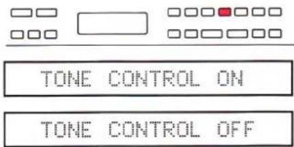
text_image
TONE CONTROL ON TONE CONTROL OFFThe TONE [29] key switches the tone controls (BASS, TREBLE) on or off so that the sound can be compared between linear (uninfluenced) and corrected frequency response. The current status of this function is shown on the display [15] for a few seconds: TONE CONTROL ON/OFF, and the bar symbols for BASS and TREBLE light up on the LC display [24].
The LOUDNESS function is automatically cancelled when this function is selected.
BASS +/− [27/25]
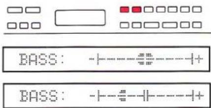
text_image
BASS: -+---#---++-++ BASS: -+---#---++-++With the bass control you can emphasize (BASS + [27]) or de-emphasize (BASS - [25]) frequencies in 4 steps.
When you press one of the bass control keys the current setting is shown on the display [15] for a few seconds and the bar symbols for BASS and TREBLE light up on the LC display [24]. Each time you press one of these keys the setting changes by an additional step in the corresponding direction.
TREBLE +/- [33/31]
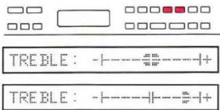
text_image
TREBLE : +----+----++ TREBLE : +----+----++With the treble control you can emphasize (TREBLE + [33]) or de-emphasize (TREBLE - [31]) in 4 steps.
When you press one of the treble control keys the current setting is shown on the display [15] for a few seconds and the bar symbols for BASS and TREBLE light up on the LC display [24]. Each time you press one of these keys, the setting changes by an additional step in the corresponding direction.
LOUDNESS [28]
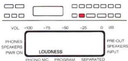
text_image
VOL -100 -75 -50 -25 0 dB PHONES SPEAKERS PWR ON LOUDNESS PHONO MC PROGRAM SEPARATED PRE-OUT SPEAKERS INPUTThe LOUDNESS [28] key activates or deactivates the tone compensated volume control which is matched to the natural characteristics of the human ear.
Based on the maximum volume set with MAX VOLUME, the bass frequencies are accentuated at reduced volumes (1 correction step per 10 dB of VOLUME decrease).
When the LOUDNESS function is activated, the manual tone controls (BASS, TREBLE) are automatically switched off. Conversely the LOUDNESS function is cancelled when you press the TONE [29] key.
Auxiliary keypad
Record (REC=IN, REC-OUT)
text_image
mediaRecording
There are two ways of making a recording. The audible signal source can also be the recording source or a different source can be selected for recording.
REC=IN [23]
TUNER
This setting is selected before the amplifier leaves the factory. The display [15] shows the selected signal source, the volume control and balance settings. The audible signal source is also the recording source available on the outputs RECORD [51], TAPE 1[50], and TAPE 2 [49].
Note:
The outputs TAPE 1 [45] and TAPE 2 [44] are mutually interlocked.
If TAPE 1 is defined as the signal source, the record output TAPE 1 [50] is disabled in order to prevent feedback. However, the signal can be recorded via TAPE 2.
REC-OUT [19]
IN: TUNER REC:
IN: TUNER REC: PHONO
When you press REC-OUT [19] the content of the display [15] changes immediately.
The word IN: is followed by the currently audible signal source (e.g. TUNER). For the record output a signal source can now be selected following REC: (e.g. PHONO). As a result you will hear the signal source TUNER via the outputs SPEAKERS A [54], SPEAKERS B [55], PRE-AMP [53], and MONITOR [48], while the PHONO signal can be recorded via the outputs TAPE 1 [50], TAPE 2 [49], and RECORD [51].
MM
text_image
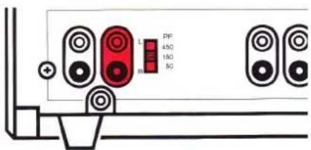
L PF 450 150 50 +Turntables equipped with a MM (moving magnet) cartridgesystem must be connected to the PHONO MM [40] input.
Correct matching of the PHONO input is essential for optimum reproduction of records. The input capacitance must, therefore, be adjusted to the cartridge system with the PF [41] switch located on the rear panel.
Exception:
When a REVOX B291 turntable is used, always select the 150 pF setting.
Matching procedure:

text_image
L R PF a60 SDFor cartridge systems Elac EMM 150 and Shure V15V the correct setting is 150 pF. The setting of other systems can be computed according to the example given below. The capacitance rating can be found in the technical specifications of the turntable and the phono cartridge system.
Example:
Nominal capacitance
| of phono cartridge: | 375 pF |
| Capacitance of turntable output (cable capacitance): | -225 pF |
| Correct setting: | 150 pF |
If the correct value cannot be set exactly, use the closest possible value. A lower setting causes accentuation of the (extreme) treble frequencies, a higher value causes losses in the (extreme) treble range.
MC [20]
text_image
VOL -100 -75 -50 -25 0 dB PHONES SPEAKERS PWR ON - BASS + - TREBLE + PRE-OUT SPEAKERS INPUT PHONO MC PROGRAM SEPARATEDTurntables equipped with a MC (moving coil) cartridge system should be connected to the PHONO MC [38] input, but in this case the amplifier must be fitted with the optional MC preamplifier.
When you press the MC [20] key, the MC preamplifier is switched on and the MM preamplifier is switched off.
Auxiliary keypad
Separating the preamplifier/power amplifier
text_image
netfoxSEPARATED [21]
![REVOX B250 - SEPARATED [21] - 1](/content/2026/02/383402/images/2adb6cd8af5e5c7ffc4b5c954435e2223b7541f6c11ae929dd434ef1771483c8.jpg)
text_image
VOL -100 -75 -50 -25 0 dB PHONES SPEAKERS PWR ON - BASS + - TREBLE + PRE-OUT SPEAKERS INPUT PHONO MC PROGRAM SEPARATEDThe SEPARATED [21] key disconnects the preamplifier from the power amplifier. This is acknowledged on the LC display [24] by an arrow pointing to the word SEPARATED. This function can be used, for example, to connect an equalizer into the signal path. The preamplifier signal is available on the PRE-AMP [53] output (selectable with the PRE-OUT [34] switch) and fed via the equalizer and the PWR-AMP [47] input to the power amplifier.
PWR-AMP [47]
![REVOX B250 - PWR-AMP [47] - 1](/content/2026/02/383402/images/b044aa126bf2bc7dff431656e75f3226b80be14e20316c492162e935b6e6de2d.jpg)
text_image
VOL -100 -75 -50 -25 0 dB PHONES SPEAKERS PWR ON - BASS + - TREBLE + PRE-OUT SPEAKERS INPUT PHONO MC PROGRAM SEPARATEDThe PWR-AMP [47] input connects the available signal directly to the power amplifier which means that it can no longer be influenced with the VOLUME keys. This input is only enabled when the preamplifier is separated from the power amplifier (SEPARATED [21] key).
MAX VOLUME [22]
The maximum adjustable volume can be defined individually for SPEAKERS A, SPEAKERS B, PREAMP, and PHONES.
The following procedure must be followed for each of the outputs. The other outputs should be switched off. If more than one output is switched on the adjustment is made for SPEAKERS A.
● Press SPEAKERS A [35] key
![REVOX B250 - PWR-AMP [47] - 2](/content/2026/02/383402/images/f16320a0f857cbf90eeba8f7a9573b7199a2315af1b2f91df5398cac95d957c1.jpg)
Switch on the output to be adjusted by pressing the corresponding key (for PHONES [18] all outputs must be switched off).
● Press the MAX VOLUME [22] key
![REVOX B250 - PWR-AMP [47] - 3](/content/2026/02/383402/images/8654ba93f7757274310734c97f7d67793a7f52cfa1350eef45d4ad0ff2ffd581.jpg)
When you press the MAX VOLUME [22] key, the input mode is activated. This is signalled on the LC display [24] by a bargraph symbol for the current setting and the message MAX VOLUME flashes. The two arrows point to PROGRAM and PHONES or SPEAKERS.
● Press the VOLUME key
![REVOX B250 - PWR-AMP [47] - 4](/content/2026/02/383402/images/747dc32f119063bbe4f2ecacde045e2880507da3bb7e0aefeb8d64b59eee55a2.jpg)
text_image
MeBoxThe desired maximum volume can now be set with the VOLUME + [2] and VOLUME - [3] keys.
● Press the STORE [36] key
![REVOX B250 - PWR-AMP [47] - 5](/content/2026/02/383402/images/9856ee369758411eb6d3c6916a8f35b177a1ea60a8fa9827120b6c016aa211b7.jpg)
When you press the STORE [36] key, the volume setting is stored as the maximum available volume for the corresponding speaker group.
Factory setting
A higher volume can only be achieved by increasing the MAX VOLUME according to the foregoing procedure.
![REVOX B250 - PWR-AMP [47] - 6](/content/2026/02/383402/images/ddd9ff4695539cc3ed015606955dc3bd8d040b794354c720d0291e13ab057d38.jpg)
text_image
RESTORE NOMINAL ?The MAX VOLUME and PWR ON VOLUME settings made by the factory prior to shipment of the unit can be reestablished at any time as follows:
![REVOX B250 - PWR-AMP [47] - 7](/content/2026/02/383402/images/0c861ad187901cae79795a6f57a0e9111dcc2cd6c5dfdda5d6c22149cf1b5555.jpg)
text_image
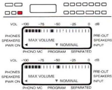
VOL -100 -75 -50 -25 0 dB PHONES SPEAKERS PWR ON MAX VOLUME PRE-OUT SPEAKERS INPUT PHONO MC PROGRAM SEPARATED VOL -100 -75 -50 -25 0 dB PHONES SPEAKERS PWR ON MAX VOLUME PRE-OUT SPEAKERS INPUT PHONO MC PROGRAM SEPARATEDRepeatedly press the MAX VOLUME [22] key until the message RESTORE NOMINAL? becomes visible on the LC display [15] and the flashing message MAX VOLUME NOMINAL appears on the LC display [24].
When you press the STORE [36] key at this point, the factory settings are reprogrammed for all outputs.
PWR-ON VOLUME
The POWER-ON VOLUME defines the volume setting at the time the amplifier is switched on, regardless of the volume setting in effect when the amplifier was switched off. The power-on volume can also be adjusted to personal requirements. However, this setting should not be adjusted to high (power-on at late hours of the night).
● Press MAX VOLUME [22] key
![REVOX B250 - ● Press MAX VOLUME [22] key - 1](/content/2026/02/383402/images/8887841ea1d62d134f935b36fbedd3f4d112aa08c8ee5c86092ada2e985073ee.jpg)
text_image
VOL -100 -75 -50 -25 0 dB PHONES SPEAKERS PWR ON MAX VOLUME PRE-OUT NOMINAL SPEAKERS INPUT PHONO MC PROGRAM SEPARATED VOL -100 -75 -50 -25 0 dB PHONES SPEAKERS PWR ON MAX VOLUME PRE-OUT NOMINAL SPEAKERS INPUT PHONO MC PROGRAM SEPARATEDRepeatedly press the MAX VOLUME [22] key until the arrow in the LC display [24] points to PWR ON. The input mode for entering the PWR-ON VOLUME is now activated. On the LC display [24] this is acknowledged with a bargraph symbol and the flashing message MAX VOLUME. The two arrows point to PROGRAM and PWR ON.
● Press VOLUME key
text_image
mnl/loxThe desired power-on volume can now be set by means of the VOLUME + [2] and VOLUME - [3] keys.
● Press STORE [36] key
![REVOX B250 - ● Press STORE [36] key - 1](/content/2026/02/383402/images/96c726f95e94f76bf85030f2551913fcc768888bd1d65547135ea6f27b88ff9c.jpg)
When you press the STORE [36] key the volume setting is stored as the PWR-ON VOLUME. You can reprogram the power-on volume at any time.
Factory setting
The factory settings for MAX VOLUME and PWR-ON VOLUME can be reestablished at any time: Repetitively press the MAX VOLUME [22] key until the message RESTORE NOMINAL? becomes visible on the LC display [15] and the flashing message MAX VOLUME NOMINAL appears on the LC display [24]. When you press the STORE [36] key at this point, the factory settings are reprogrammed for all outputs.
Auxiliary keypad
Adjustments: SENSITIVITY: SPEAKERS, PRE-OUT
text_image
redboxSENSITIVITY [26]
With the SENSITIVITY key it is possible to adjust the preamplifier output level relative to the output level of the SPEAKERS A/B outputs and to increase or decrease the nominal output level of one speaker group relative to the other group. In addition the gain of the input amplifier can be matched to the levels of the individual signal sources.
If several outputs are simultaneously active, the nominal output level is governed by the output with the highest priority:
1st priority: SPEAKERS A
2nd priority: SPEAKERS B
No priority: PRE-OUT
Each input and output can be adjusted individually.
● Press SPEAKERS A [35] key
![REVOX B250 - SENSITIVITY [26] - 1](/content/2026/02/383402/images/19e01cd1642fcc062de85d702d6cc737c8d88b02bc42136705a63b18a520fd9a.jpg)
Activate the output to be adjusted by pressing the corresponding key. Switch-off the other outputs (PRE-OUT, SPEAKERS B).
● Press SENSITIVITY [26] key
![REVOX B250 - SENSITIVITY [26] - 2](/content/2026/02/383402/images/0d658686a2a1ecf70a54294954d0bbe67f5448fc26d436079fd87a24d73ce924.jpg)
text_image
VOL -100 -75 -50 -25 0 dB PHONES - 0 + SPEAKERS SENSITIVITY ► PRE-OUT PWR ON INPUT PHONO MC PROGRAM SEPARATEDThe SENSITIVITY [26] key activates the input mode. On the LC display [24] this is acknowledged with a bargraph symbol for the current setting and the flashing message SENSITIVITY. The two arrows point to PROGRAM and SPEAKERS.
● Press VOLUME key
![REVOX B250 - SENSITIVITY [26] - 3](/content/2026/02/383402/images/798e68428047ce20b78d30d5af7dba359c486c84fd21c89b95c2275d2df896ff.jpg)
text_image
mdVox VOL -100 -75 -50 -25 0 dB PHONES SPEAKERS PWR ON - 0 + SENSITIVITY ► PRE-OUT SPEAKERS INPUT PHONO MC PROGRAM SEPARATEDThe level of the activated output can now be increased or decreased by means of the VOLUME + [2] and VOLUME - [3] keys.
● Press STORE [36] key
![REVOX B250 - SENSITIVITY [26] - 4](/content/2026/02/383402/images/1ebb2e4ad16154cfb0c7edab915e8b23b857eb7bfc9dfc714e2daac4389fdf9a.jpg)
When you press the STORE [36] key the volume setting is stored. You can reprogram the level at any time.
Factory setting
The factory sensitivity setting can be reestablished at any time: Repeatedly press the SENSITIVITY [26] key until the message RESTORE NOMINAL? becomes visible on the LC display [15] and the flashing message SENSITIVITY NOMINAL appears on the LC display [24]. When you press the STORE [36] key at this point, the factory settings are reprogrammed for all inputs and outputs.
Auxiliary keypad
Adjustments: INPUT SENSITIVITY
text_image
meBox 1.0SENSITIVITY [26]
With the SENSITIVITY key it is possible to adjust the preamplifier output level relative to the output level of the signal sources. Each input is individually adjustable.
● Press TUNER [12] key
![REVOX B250 - ● Press TUNER [12] key - 1](/content/2026/02/383402/images/a3b220a933e6900c13ea02030577d5832e29f0761b353a9185b067923c17958b.jpg)
text_image
intbox TUNERSelect the signal source to be adjusted (TUNER, TAPE 1/2, AUX, CD, PHONO, TV, VCR 1/2, DISC) by pressing the appropriate key.
● Press SENSITIVITY [26] key
![REVOX B250 - ● Press SENSITIVITY [26] key - 1](/content/2026/02/383402/images/de73b3a204be78800748c9ab389f40a776c841903afc9281e78a0a1f51e14793.jpg)
text_image
VOL -100 -75 -50 -25 0 dB PHONES SPEAKERS PWR ON - 0 + SENSITIVITY PRE-OUT SPEAKERS INPUT PHONO MC PROGRAM SEPARATED VOL -100 -75 -50 -25 0 dB PHONES SPEAKERS PWR ON - 0 + SENSITIVITY PRE-OUT SPEAKERS INPUT PHONO MC PROGRAM SEPARATEDRepeatedly press the SENSITIVITY [26] key until the arrow on the LC display [24] points to INPUT. This activates the mode for entering the sensitivity of the inputs. On the LC display [24] this is acknowledged with a bargraph symbol for the current setting and the flashing message SENSITIVITY. The two arrows point to PROGRAM and INPUT.
● Press STORE [36] key
![REVOX B250 - ● Press STORE [36] key - 1](/content/2026/02/383402/images/61b386168b1cc99429f001edc5e471b7dfa7f6f1a53f2c3b1657635ea99e92cc.jpg)
text_image
TUNER: MEASURING TUNER: LOW LEVELWhen you press the STORE [36] key the level measurement is automatically activated for the corresponding input. When you release the STORE [36] key the gain of the corresponding input amplifier is matched to the measured level and stored. During the measurement operation the message MEASURING appears on the display [15] behind the signal source. If the signal source does not supply a signal or if the signal is too low (switched off), the message LOW LEVEL appears and the gain of the input amplifier is not changed.
Factory setting
The factory sensitivity setting can be reestablished at any time:
Repeatedly press the SENSITIVITY [26] key until the message RESTORE NOMINAL? becomes visible on the LC display [15] and the flashing message SENSITIVITY NOMINAL appears on the LC display [24].
When you press the STORE [36] key at this point, the factory settings are reprogrammed for all inputs and outputs.
SECTION 4
Fault messages
<<<<, OVERLOADED !!!, BREAKDOWN!!!
text_image
NBCbox

text_image
meVboxThe volume is automatically decreased by 10 dB if the temperature of the output power stages becomes too high.
This process is indicated on the display [15] by the flashing symbol in place of the balance setting. The volume can be further decreased with the VOLUME keys, but not increased until the indication disappears.

After the output power stages have cooled off, the display [15] returns to the usual format, i.e. the signal source and the recording source, or the signal source, volume and balance settings are shown. The volume can now be increased as desired. However, the cause for the fault message (possibly insufficient ventilation) should be investigated.
OVERLOADED!!!


If the output power stages do not cool off after the <<< message has been displayed and their temperature continuous to increase, the fault message OVERLOADED !!! is shown on the display [15] and the speaker outputs are switched off.
After the output power stages have cooled off and the message has disappeared, the speakers can be switched on again by pressing the keys SPEAKERS A [35] and/or SPEAKERS B [37].
BREAKDOWN!!!

text_image
adVoxIn the event of severe overloading (e.g. manipulation of the connectors while the amplifier is switched on and the volume is all the way up), the speakers are muted. This fault is indicated by the message BREAKDOWN!!! on the display [15].
To remedy this fault, switch the amplifier off, check that all cables and connectors are firmly seated, and switch the amplifier back on after a reasonable pause.
Fault control
Troubleshooting
text_image
netBoxBefore you suspect a fault in the amplifier, make sure that the unit is correctly installed and that it is being operated in accordance with these instructions.
Speakers are dead

Check the speaker connections.
Has the speaker group been switched on (with SPEAKERS A [35], SPEAKERS B [37], PRE-OUT [34])?
Has the power amplifier been SEPARATED from the preamplifier? Press the SEPARATED [21] key again.
Has any signal source been selected and switched on?
text_image
netboxInsufficient output power

Has the MAX VOLUME been inadvertently set too low? You can check this by reestablishing the factory setting (RESTORE NOMINAL?).
No reproduction in PHONO mode
natural_image
Front view of a network device rear panel with ports and connectors (no visible text or labels)Has the turntable been connected to the correct PHONO input (MM [40] or MC [38])? Has the correct cartridge system been selected on the amplifier (press MC [20] key for an MC cartridge)?
text_image
MeVoxRecording on TAPE not possible
natural_image
Back panel of a computer interface showing ports and connectors (no visible text or labels)Are the INPUTS of the tape recorder connected to the OUTPUTS TAPE 1 [50] or TAPE 2 [49]?
The amplifier cannot be operated

Your amplifier is controlled and monitored by a microprocessor. When line voltage is applied this microprocessor is automatically initialized.
Faults in the AC supply system and other faults can put the microprocessor into an undefined state. The amplifier can no longer be operated.
The microprocessor can be restarted by pressing the RESET button above the SEPARATED [21] key by means of a pointed object (bent open paper clip).
Since the circuit conditions of the audio paths cannot be monitored during the reinitialization process, the speakers should preferably be disconnected from the amplifier.
If the power plug is readily accessible, it is better to disconnect it from the AC outlet for approx. 15 seconds rather than actuating the RESET button.
During the initialization of the microprocessor certain segments of the display [15] may briefly light up. This is a normal process and does not damage the amplifier.
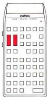
REVOX B208
text_image
mMax 0.256 - 198.0% CONTROLWith the REVOX B208 infrared remote control you can conveniently control the audio functions of the complete REVOX hi-fi system from your listening position.
text_image
MeVoxIn addition to the functions of the main keypad of the REVOX B250 amplifier, you can remote control the outputs SPEAKERS A, SPEAKERS B, PRE-OUT, the BALANCE setting and the tone control functions (TONE, BASS, TREBLE).
Operating characteristics
With the IR remote control the amplifier can be operated in the same manner as on the unit itself, except for the following special cases.
Power on
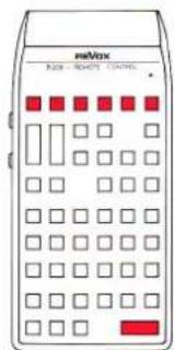
text_image
meVox RIO - RIOPTI CONTROLThe amplifier can only be powered on with the IR remote control by selecting a source (TUNER, TAPE 1/2, AUX, CD, PHONO). If you press the POWER OFF key on the IR remote control, all REVOX IR-equipped components in the entire hi-fi system will be switched off.
TV, VCR 1/2, DISC
text_image
mBox M-200 - 100000 100000The additional signal sources accessible with the REVOX B200 · Controller are activated with the remote control by pressing the * key together with the corresponding source selection key.
REC-OUT
IN:TUNER REC:PHONO
text_image
ReVox 12:00 14:00 16:00If the amplifier is operating in REC-OUT mode (REC-OUT [19] key), the signal source to which you are currently listening can also be the recording source by pressing the REC=MON key on the IR remote control. You can then press a source selection key for listening to another signal source without changing the recording source.
VOLUME +/-
TUNER
text_image
radlox 928 MHz 100MHzWhen you briefly press the VOLUME key on the IR remote control, the volume is changed in small steps (1 dB), if you hold down this key continuously the volume changes in larger steps (3 dB).
Changing the line voltage
natural_image
Technical line drawing of a mechanical device with rollers and a rotating arrow (no text or symbols)The amplifier can be switched over to different line voltages but this work should be performed by your dealer!
Disconnect the power cord!
Remove the top cover and the left-hand side panel.
Lift the protective foil and adjust the line voltage.
Glue a rating label that corresponds to the new line voltage over the 220V\~marking below the power inlet on the rear panel.
Power fuse
If the line voltage setting is changed, the power fuses must be checked and matched to the new line voltage, if necessary.
100...140VAC: 6.3A/250V (SLOW)
200 ... 240VAC: 3.15A/250V (SLOW)
Completely reassemble the unit before you reconnect it to the AC power outlet.
IEC standards
| Peak output power: | into 4 Ohm: | 2x300W |
| into 8 Ohm: | 2x160W | |
| 1kHz signal; 1 period on, 16 periods off | ||
| Continuous power output: | into 4 Ohm: | 2x200W |
| (DIN 45500) | into 8 Ohm: | 2x120W |
| Damping factor: | at 1 kHz into 8 Ohm: | >100 |
| Harmonic distortion: | at 1 kHz, 180 W into 4 Ohm: | <0.006% |
| Rise time: | for 4 Ohm load: | 4μs |
| for 8 Ohm load: | 3μs | |
| Inputs | ||
| Sensitivity/impedance: | (for 1 kHz at 200 W into 4 Ohm) | |
| - TUNER, TAPE 1, TAPE 2, AUX, CD: | 250 mV/47 kOhm, nominal 500 mV | |
| - PHONO MM: | 2.5 mV/47 kOhm; 50, 150, 450 pF; nominal 5 mV | |
| - PHONO MC (option): | 140 μV/100 Ohm, nominal 0.5 mV | |
| - PWR-AMP: | 2.8 V/47 kOhm | |
| Outputs | ||
| Level/impedance: | (at nominal input voltage) | |
| - REC, MONITOR, TAPE 1, TAPE 2: | 500 mV/440 Ohm | |
| - from PHONO MM input: | 250 mV | |
| - PRE-AMP: | 2.8 V/440 Ohm | |
| - PHONES: | 9.8 V/280 Ohm | |
| - SPEAKERS A/B: | 28.3 V/80 mOhm | |
| Tone control response: | (parametric in ±4 steps) | |
| BASS at 40 Hz: | -12 dB ... +12 dB | |
| TREBLE at 14 kHz: | -12 dB ... +12 dB | |
| Signal-to-noise-ratio: | linear (at nominal input voltage) | |
| - TUNER, TAPE 1, TAPE 2, AUX, CD: | ||
| at 200 W into 4 Ohm, 1kOhm termination: 98 dB | ||
| at 50 mW into 4 Ohm, 1kOhm termination: 76 dB | ||
| - PHONO MM: | at 200 W into 4 Ohm, 1kOhm termination: 76 dB | |
| at 50 mW into 4 Ohm, 1kOhm termination: 75 dB | ||
| - PHONO MC (option): | at 200 W into 4 Ohm, 1kOhm termination: 73 dB | |
| at 50 mW into 4 Ohm, 1kOhm termination: 70 dB | ||
| Maximum input voltage: | TUNER, TAPE 1, TAPE 2, AUX, CD: | 10 V |
| PHONO MM: | 200 mV | |
| PHONO MC (option): | 10 mV | |
| Crosstalk attenuation: | ||
| - Between inputs: | at 10 kHz, 1kOhm termination: | 100 dB |
| - Tape/source: | at 10 kHz, 1kOhm termination: | 80 dB |
| Channel separation: | ||
| - TUNER, TAPE 1, TAPE 2, AUX, CD: | ||
| at 1 kHz, 1kOhm termination: | 86 dB | |
| - PHONO: | at 1 kHz, 1kOhm termination: | 55 dB |
| Frequency response: | 20 Hz ... 20 kHz: | +0 dB/-0.2 dB |
| PHONO RIAA equalization: 4 times constants. 20Hz...20kHz ±0.3dB | ||
| Power requirements: | internally adjustable100, 120, 140, 200, 220, 240VAC, +5%/-10%50Hz...60Hz | |
| Power fuse: | 100V...140VAC:200V...240VAC: | T6.3A/250V (SLOW)T3.15A/250V (SLOW) |
| Power consumption: | maximum:in standby, approx.: | 800W10W |
| Dimensions: | (W×H×D): | 450×109×332mm |
| Weight: | approx.: | 15kg |
Subject to change.
IHF standards
| Continuous average Power output: | 20Hz...20kHz, THD <0.015%, at 4Ohm: | 2×150W |
| at 8Ohm: | 2×100W | |
| Dynamic headroom: | at 4Ohm: | 2.8dB |
| at 8Ohm: | 1.9dB | |
| Frequency response: | 20Hz...20kHzHigh level inputs: | +0 dB/−/0.2 dB |
| PHONO RIAA equalization: | ±0.3 dB | |
| Sensitivity: | for 100W at 8Ohm | |
| - TUNER, TAPE 1, TAPE 2, AUX, CD: | 250 mV | |
| - PHONO MM: | 2.5 mV | |
| - PHONO MC (option): | 140μV | |
| - POWERAMP: | 2.8V | |
| A-weighted Signal-to-noise-ratio: | referred to 100W at 8Ohm | |
| - TUNER, TAPE 1, TAPE 2, AUX, CD: | 103 dB | |
| - PHONO MM: | 80 dB | |
| - PHONO MC (option): | 75 dB | |
| Maximum input signal: | ||
| - TUNER, TAPE 1, TAPE 2, AUX, CD: | 10V | |
| - PHONO MM: | 200 mV | |
| - PHONO MC (option): | 10 mV | |
| Input impedance: | ||
| - TUNER, TAPE 1, TAPE 2, AUX, CD: | 47 kOhm | |
| - PHONO MM: | 47 kOhm; 50, 150, 450 pF | |
| - PHONO MC (option): | 100 Ohm | |
| - POWERAMP: | 47 kOhm | |
| Output impedance: | ||
| - TAPE 1, TAPE 2, REC, MONITOR, PREAMP: | 440 Ohm | |
| - PHONES: | 280 Ohm | |
| - SPEAKERS A/B: | 80 mOhm | |
| Damping factor: | at 1 kHz referenced to 8 Ohm: | 100 |
| Tone-control response: | BASS at 40Hz: | -12 dB...+12 dB |
| TREBLE at 14 kHz: | -12 dB...+12 dB | |
| Crosstalk: | between inputs at 10 kHz: | 100 dB |
| Channel separation: | ||
| - TUNER, TAPE 1, TAPE 2, AUX, CD: | ||
| - PHONO: | at 1 kHz: | 86 dB |
| at 1 kHz: | 55 dB | |
| Power supply: | internal switch for 100, 120, 140, 200, 220, 240 VAC, +5%/-10%50 Hz...60 Hz | |
| Power fuse: | 100V...140 VAC: | T6.3 A/250V (SLOW) |
| 200V...240 VAC: | T3.15 A/250V (SLOW) | |
| Power consumption: | max. | 800 W |
| Standby mode: | approx. 10 W | |
| Dimensions: | (W x HxD): | 450 x109 x332 mm |
| Weight: | approx. | (33 lbs| 15 kg |
Subject to change.
Dimensions
text_image
461.2 reVox 104 57.15 450
text_image
ca.28 332
natural_image
Front view of a rectangular electronic device with vertical slots and top tabs (no text or symbols)Index of keypad functions
Quick-reference description of all functions
natural_image
Front view of a vintage remote control unit (no visible text or labels)●)) Functions that respond to the REVOX B208 IR remote control.
Front panel:
| Operating element | Function | Page | ||
| [1] | POWER | ●)) | On/off switch. The amplifier is switched on in the last active mode. The amplifier is switched off (standby) when this key is pressed again. | 7 |
| [2] | VOLUME + | ●)) | Increases the volume. With > in 1 dB steps, with >> in 3 dB steps. Increases the level in programming mode. | 10 |
| [3] | VOLUME - | ●)) | Decreases the volume. With < in 1 dB steps, with << in 3 dB steps. Decreases the level in programming mode. | 10 |
| [4] | OPEN | Opens the hinged cover of the auxiliary keypad and contains the IR receiver. To reclose the cover simply push it up. | 11 | |
| [5] | -20 dB | ●)) | Decreases the volume by - 20 dB each time this key is pressed. Can be reset with VOLUME + [2]. | 10 |
| [6] | VIDEO | Only active in conjunction with the REVOX B200 · Controller. Can be used for selecting additional signal sources such as TV, VCR 1/2 and DISC. | 10 | |
| [7] | PHONO | ●)) | Signal source selection key for turntable. | 9 |
| [8] | CD | ●)) | Signal source selection key for CD player. | 9 |
| [9] | AUX | ●)) | Signal source selection key for the auxiliary input. | 9 |
| [10] | TAPE 2 | ●)) | Signal source selection key for tape recorder 2. | 9 |
| [11] | TAPE 1 | ●)) | Signal source selection key for tape recorder 1. | 9 |
| [12] | TUNER | ●)) | Signal source selection key for tuner. | 9 |
| [13] | PRE-OUT | This pilot LED is lit when the preamplifier output PRE-OUT is activated. | 11 | |
| [14] | REMOTE | This LED is lit when an IR signal is being received. | 24 | |
| [15] | Display | 20-position vacuum fluorescence display. Indicates the operating state of the amplifier. | 9 | |
| [16] | SPEAKERS B | This LED is lit when the SPEAKERS B output is switched on. | 11 | |
| [17] | SPEAKERS A | This LED is lit when the SPEAKERS A output is switched on. | 11 | |
| [18] | PHONES | Headphones socket. | 11 | |
| [19] | REC-OUT | The recording source differs from the listening source. The display [15] changes the indicating mode to e.g.: IN:TUNER REC:TAPE1. | 13 | |
| [20] | MC | Selects the moving coil PHONO preamplifier if the MC option is installed, otherwise this key is inactive. | 14 | |
| [21] | SEPARATED | Separates the preamplifier from the power amplifier so that e.g. an equalizer can be looped in. | 15 | |
| Operating element | Function | Page | |
| [22] | MAX VOLUME | Activates the mode for programming the MAX VOLUME of the individual outputs and the PWR-ON VOLUME. | 17 |
| [23] | REC=IN | The recording source is the same as the listening source. The display [15] changes the indicating mode to: signal source, volume, and balance setting. | 13 |
| [24] | LC display | Multifunction display field with indicators for: BASS, TREBLE, MAX VOLUME, SENSITIVITY, etc. | 11 |
| [25] | BASS - | ●)) Reduces the content of low frequencies. The current setting is displayed when you press this key the first time. | 12 |
| [26] | SENSITIVITY | Activates the mode for programming relative volume levels between all audio inputs and between speakers pairs. Compensation in favor of an output and the SENSITIVITY of the signal sources. | 18 |
| [27] | BASS + | ●)) Increases the content of low frequencies. The current setting is displayed when you press this key the first time. | 12 |
| [28] | LOUDN | Switches the tone compensated volume control (LOUDNESS function) on and off. | 12 |
| [29] | TONE | ●)) Switches the tone control (BASS, TREBLE) on and off. | 12 |
| [30] | BALANCE | ●)) Shifts the output level in favor of the left channel. | 12 |
| [31] | TREBLE - | ●)) Decreases the content of high frequencies. The current setting is displayed when you press this key the first time. | 12 |
| [32] | BALANCE R | ●)) Shifts the output level in favor of the right channel. | 12 |
| [33] | TREBLE + | ●)) Increases the content of high frequencies. The current setting is displayed when you press this key the first time. | 12 |
| [34] | PRE-OUT | ●)) Switches the preamplifier output PRE-AMP on and off. | 11 |
| [35] | SPEAKERS A | ●)) Switches SPEAKERS A on and off. | 11 |
| [36] | STORE | Stores the programmed MAX VOLUME or SENSITIVITY setting (except SENSITIVITY INPUT). A programming sequence can be cancelled at any time without storing by simply closing the cover. | 16 |
| [37] | SPEAKERS B | Switches SPEAKERS B on and off. | 11 |
Rear panel:
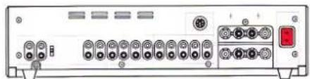
| Operating element | Function | Page | |
| [38] | PHONO MC | Input sockets (CINCH) for a turntable with moving coil cartridge system (option). | 14 |
| [39] | Terminal for turntable ground. | 5 | |
| [40] | PHONO MM | Input sockets (CINCH) for a turntable with moving magnet cartridge system. | 14 |
| [41] | PF | Switch for matching the input capacitance of the PHONO MM input to the capacitance of the turntable. | 14 |
| [42] | CD | Input sockets (CINCH) for a CD player. | 5 |
| [43] | AUX | Input sockets (CINCH) for an additional signal source (auxiliary input). | 5 |
| [44] | TAPE 2 | Input sockets (CINCH) for playback from tape recorder 2. | 5 |
| [45] | TAPE 1 | Input sockets (CINCH) for playback from tape recorder 1. | 5 |
| [46] | TUNER | Input sockets (CINCH) for a tuner. | 5 |
| [47] | PWR-AMP | Input sockets (CINCH) for direct feeding into the amplifier stage. | 15 |
| [48] | MONITOR | Output sockets (CINCH) with fixed level for an additional amplifier. | 6 |
| [49] | TAPE 2 | Output sockets (CINCH) for recording with tape deck 2. | 6 |
| [50] | TAPE 1 | Output sockets (CINCH) for recording with tape deck 1. | 6 |
| [51] | RECORD | Output sockets (CINCH) for an additional recording channel (third tape deck). | 7 |
| [52] | SERIAL LINK | Serial control terminal for connecting an external REVOX B206 IR receiver. | |
| [53] | PRE-AMP | Output sockets (CINCH) for connecting active speakers (preamplifier output). | 6 |
| [54] | SPEAKERS A | Speaker terminals for speaker group A. | 6 |
| [55] | SPEAKERS B | Speaker terminals for speaker group B. | 6 |
| [56] | AC POWER | Power connection. | 7 |
Quick-reference diagram
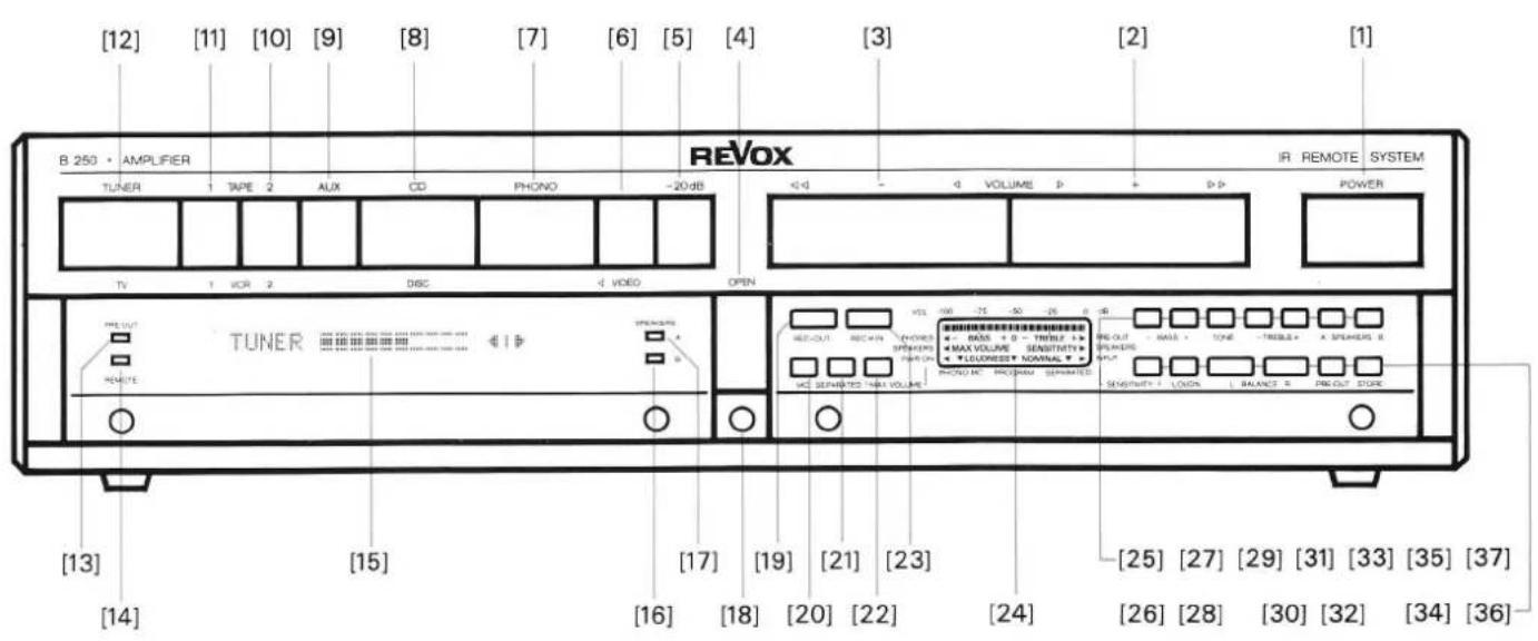
text_image
[12] [11] [10] [9] [8] [7] [6] [5] [4] [3] [2] [1] B 250 • AMPLIFIER TUNER 1 TAPE 2 AUX CD PHONO -20 dB TV 1 VCR 2 DISC 4 VIDEO OPEN IR REMOTE SYSTEM POWER TUNER OPEN [13] [15] [17] [19] [21] [23] [25] [27] [29] [31] [33] [35] [37] [14] [16] [18] [20] [22] [24] [26] [28] [30] [32] [34] [36]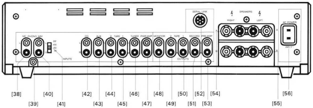
text_image
MC PHONO MM L PF 450 150 36 INPUTS CD AUX 2 TAPE 1 TUNER PWR-AMP MONITOR 2 TAPE 1 RECORD PRE-AMP R OUTPUTS SERIAL LINK A RIGHT SPEAKERS LEFT A AC POWER B 220 V+ [38] [40] [42] [44] [46] [48] [50] [52] [54] [39] [41] [43] [45] [47] [49] [51] [53] [56] [55]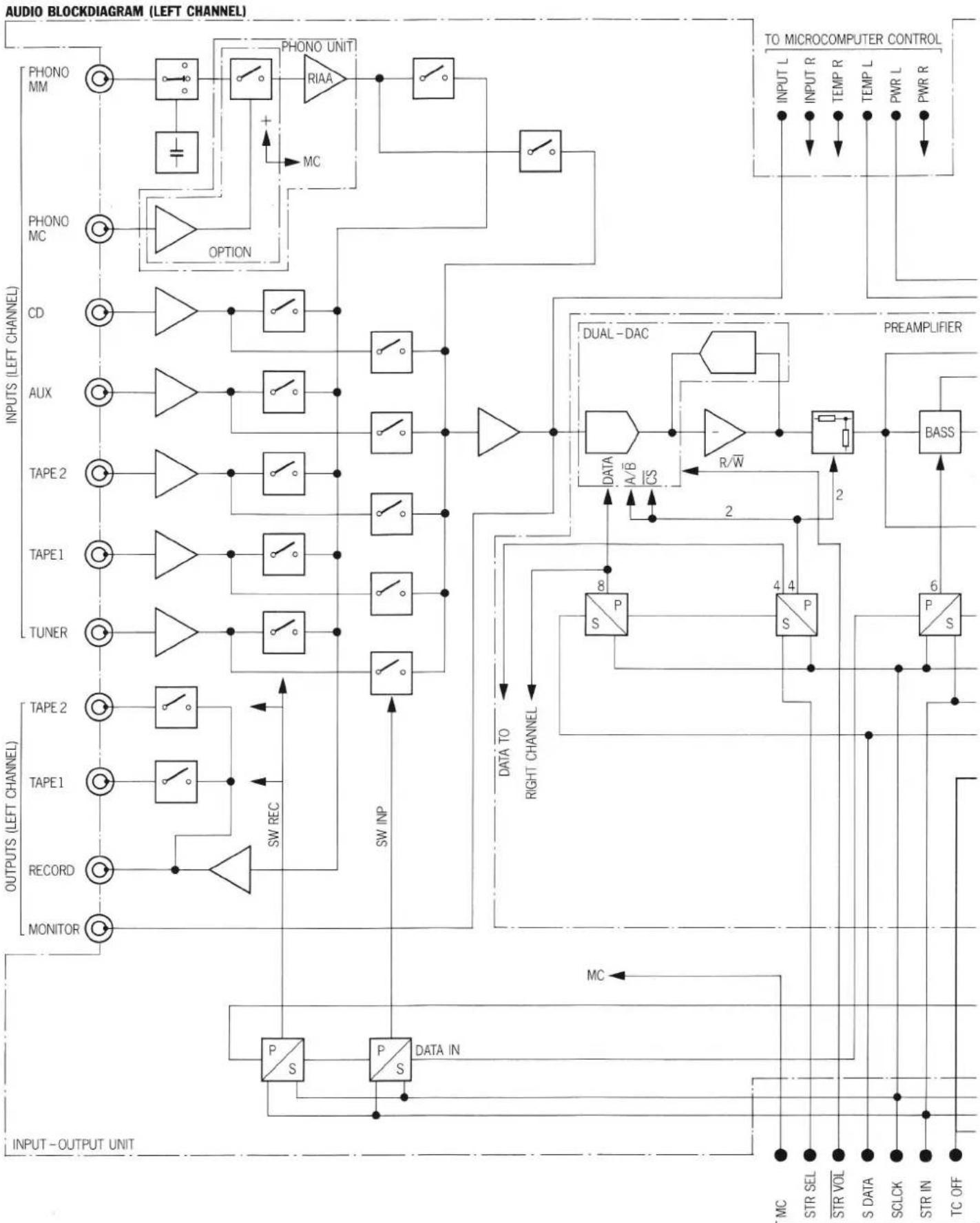
flowchart
graph TD
    subgraph_Left_Channel["OUTPUTS (LEFT CHANNEL)"]
        direction TB
        MONITOR1["MONITOR"] --> RECORD["RECORD"]
        RECORD --> TAPE1["TAPE1"]
        TAPE1 --> TAPE2["TAPE2"]
        TAPE2 --> TUNER["TUNER"]
        TUNER --> TAPE1
        TAPE1 --> TAPE2
        TAPE2 --> TAPE1
        TAPE2 --> TAPE2
        TAPE1 --> TAPE2
        TAPE2 --> TAPE1
        TAPE1 --> AUX["AUX"]
        TAPE2 --> AUX
        AUX --> CD["CD"]
        CD --> PHONO["PHONO"]
        PHONO --> MM["MM"]
    end

    subgraph_Right_Channel["INPUTS (LEFT CHANNEL)"]
        direction TB
        SNPS["PS"] --> DATA_IN["DATA IN"]
        DATA_IN --> SWINP["SW INP"]
        SWINP --> SNPS
        SNPS --> DATA_TO_RIGHT_CHANNEL["DATA TO RIGHT CHANNEL"]
        DATA_TO_RIGHT_CHANNEL --> SPP["S/P 8"]
        SPP --> DATA_A/B_CS["A/B/CS"]
        DATA_A/B_CS --> R/W["R/W"]
        R/W --> DUAL_DAC["DUAL-DAC"]
        DUAL_DAC --> BASS["BASS"]
    end

    subgraph_Micro_Control_Circuit["To MICROCOMPUTER CONTROL"]
        direction TB
        INPUTL["INPUT L"]
        INPUTR["INPUT R"]
        TEMPR["TEMP R"]
        TEMPL["TEMP L"]
        PWRL["PWR L"]
        PWRR["PWR R"]
    end

    %% Legend
    subgraph_Audio_BlockDiagram["AUDIO BLOCKDIABRAM (LEFT CHANNEL)"]
        direction TB
        ONION["OPTION"] --> RAA["RAA"]
        RAA --> MM["MM"]
        MM --> PHONO
    end
flowchart
graph TD
    A["Speaker A (LEFT)"] --> B["SP A"]
    C["Speaker B (LEFT)"] --> D["SP B"]
    E["Phone 6"] --> F["P S"]
    G["Pre OUT WITH TC"] --> H["P IN"]
    I["Pre OUT DIRECT"] --> J["P IN"]
    K["PreAMP OUTPUT (LEFT)"] --> L["P IN"]
    M["POWER FAIL DETECT"] --> N["POWER SUPPLY"]
    O["HEAT SINK POWER AMP"] --> P["TC OFF"]
    Q["6"] --> R["TRE-BLE"]
    S["2"] --> T["P S"]
    U["THAT"] --> V["TC OFF"]
    W["THAT"] --> X["TC OFF"]
    Y["THAT"] --> Z["TC OFF"]
    AA["THAT"] --> AB["TC OFF"]
    AC["THAT"] --> AD["TC OFF"]
    AE["THAT"] --> AF["TC OFF"]
    AG["THAT"] --> AH["TC OFF"]
    AI["THAT"] --> AJ["TC OFF"]
    AK["THAT"] --> AL["TC OFF"]
    AM["THAT"] --> AN["TC OFF"]
    AO["THAT"] --> AP["TC OFF"]
    AQ["THAT"] --> AR["TC OFF"]
    AS["THAT"] --> AT["TC OFF"]
    AU["THAT"] --> AV["TC OFF"]
    AW["THAT"] --> AX["TC OFF"]
    AY["THAT"] --> AZ["P S EN"]
    BA["THAT"] --> BB["P S EN"]
FRANÇAIS ____
F
Mode d'emploi
natural_image
Black-and-white photo of a cardboard box, a laptop, and a printed notebook with cable (no visible text or symbols)text_image
10 mm wellsnatural_image
Front view of a vintage electronic device with ports and indicator lights (no visible text or symbols)natural_image
Front view of a rack-mounted electronic device with ports and connectors (no visible text or labels)natural_image
Back panel of a computer interface showing ports, connectors, and a power connector (no visible text or labels)natural_image
Diagram of a device rear panel connected to a terminal block, showing pin connections and red connectors (no text or labels)natural_image
Diagram of a device rear panel connected to a cable, showing ports and connectors (no text or labels)TAPE 1 [50], TAPE 2 [49]
text_image
0], TAPE 2 [49] Tape 2natural_image
Front view of a portable electronic device labeled 'mcVox' (no visible text or symbols on the device body)RECORD [51]
text_image
51]Tape 3
natural_image
Front view of a computer rack with ports and connectors (no visible text or labels)natural_image
Front view of a red and white electronic device with ports and buttons (no visible text or symbols)TUNER [12], CD [8], AUX [9]
text_image
TUNER CD AUXtext_image
TAPE 1 TAPE 2natural_image
Front view of a red and white electronic device with ports and buttons (no visible text or symbols)VOLUME +/− [2/3]


text_image
L - R L - H - R L - H - Rtext_image
L R PF 40Hz +● Presser la touche MAX VOLUME [22]

● Presser la touche MAX VOLUME [22]
text_image
VOL -100 -75 -50 -25 0 dB PHONES SPEAKERS PWR ON MAX VOLUME PRE-OUT ↓ NOMINAL SPEAKERS INPUT PHONO MC PROGRAM SEPARATED VOL -100 -75 -50 -25 0 dB PHONES SPEAKERS PWR ON MAX VOLUME PRE-OUT ↓ NOMINAL SPEAKERS INPUT PHONO MC PROGRAM SEPARATEDnatural_image
Line drawing of a beige electronic device front panel with ports and buttons (no text or symbols)natural_image
Front view of a rack-mounted electronic device with multiple ports and connectors (no visible text or labels)natural_image
Back panel of a computer interface showing ports and connectors (no visible text or labels)natural_image
Front view of a beige NEVOX radio receiver with red buttons and indicator lights (no visible text or labels)natural_image
Technical line drawing of an industrial machine with rollers and a rotating component (no text or symbols)100 ... 140VAC: T6,3A/250V (SLOW)
200...240VAC: T3,15A/250V (SLOW)