SC8000 - Vacuum Cleaner NILFISK - Free user manual and instructions
Find the device manual for free SC8000 NILFISK in PDF.
| Product Type | Ride-on scrubber-drier |
| Brand | Nilfisk |
| Model | SC8000 |
| Power Source | Diesel or LPG (propane) |
| Transport Weight | Approximately 1410 kg (3110 lb) |
| Solution Tank Capacity | 100 gallons (378.54 L) maximum |
| Recovery Tank Capacity | Not specified (equipped with shut-off float) |
| Main Functions | Scrubbing, vacuuming, side sweeping, EcoFlex detergent system |
| Sound Pressure Level | 84.5 dB(A) (LpA) |
| Sound Power Level | 104.4 dB(A) (LwA) |
| Maximum Incline in Scrubbing | 10.5% (6°) |
| Maximum Incline in Transport | 16% (9°) |
| Engine Oil Type (Diesel) | SAE 10W-30, 20, or 10W depending on temperature |
| Engine Oil Type (LPG) | SAE 10W-30 or 5W-30 depending on temperature |
| Hydraulic Oil Type | Engine oil SAE 10W30 (before serial number 1000068541) or ISO 32 (after) |
| Maintenance** | Daily checks (oil, coolant, filters) and weekly maintenance |
| Safety** | Parking brake, main switch, optional overhead guard (FOPS) |
| Spare Parts and Repairability | Contact an authorized Nilfisk dealer for genuine parts |
| Intended Use | Commercial use (hotels, schools, hospitals, factories, stores, offices) |
Frequently Asked Questions - SC8000 NILFISK
User questions about SC8000 NILFISK
0 question about this device. Answer the ones you know or ask your own.
Ask a new question about this device
Download the instructions for your Vacuum Cleaner in PDF format for free! Find your manual SC8000 - NILFISK and take your electronic device back in hand. On this page are published all the documents necessary for the use of your device. SC8000 by NILFISK.
USER MANUAL SC8000 NILFISK
Instructions for use
Instructions for Use
Original Instructions
natural_image
Technical line drawing of a vehicle chassis with internal components (no text or symbols)
Models:
56108124 (1300 LPG), 56108125 (1300 D)
56108126 (1600 LPG), 56108127 (1600 D), 56384395 (1200 LPG)

Nilfisk
TABLE OF CONTENTS
PAGE
Introduction....A-3
Cautions and Warnings ......A-4 – A-5
Know Your Machine ....A-6 – A-9
Prepare the Machine for Use
General Information ......A-10
Pre-operational Checklist A-11 - A-12
Hydraulic Oil A-11
Engine Oil A-11
Engine Coolant A-12
Engine Air Filter A-12
Fuel A-12
Install the Brushes ...... A-13
Filling the Solution Tank A-14
Operating the Machine
Starting the Engine A-15
Detergent System ......A-16 – A-17
Scrubbing ......A-18 – A-19
Wet Vacuuming A-18
After Using the Machine
After Use A-20
Shutting Down the Engine A-20
Maintenance
Maintenance Schedule A-20
Lubricating the Machine ....A-20 – A-21
Side Broom Maintenance A-22
Dustguard Nozzle Cleaning Procedure ...... A-22
Squeegee Maintenance A-23
Squeegee Adjustment ...... A-23
Side Skirt Maintenance A-24
Debris Hopper Maintenance A-25
Troubleshooting....A-26 – A-27
Technical Specifications ...... A-28
INTRODUCTION
This manual will help you get the most from your Nilfisk Rider Scrubber. Read it thoroughly before operating the machine.
Note: Bold numbers in parentheses indicate an item illustrated on pages 6 – 9.
PARTS AND SERVICE
Repairs, when required, should be performed by your Authorized Nilfisk Service Center, who employs factory trained service personnel, and maintains an inventory of Nilfi sk original replacement parts and accessories.
Call the NILFISK DEALER named below for repair parts or service. Please specify the Model and Serial Number when discussing your machine.
MODIFICATIONS
Modifications and additions to the cleaning machine which affect capacity and safe operation shall not be performed by the customer or user without prior written approval from Nilfisk Inc. Unapproved modifications will void the machine warranty and make the customer liable for any resulting accidents.
NAME PLATE
The Part Number and Serial Number of your machine are shown on the Nameplate on the machine. This information is needed when ordering repair parts for the machine. Use the space below to note the Part Number and Serial Number of your machine for future reference.
PART NO.
SERIAL NO.
UN-CRATING
Upon delivery, carefully inspect the shipping crate and the machine for damage. If damage is evident, save all parts of the shipping crate so that they can be inspected by the trucking company that delivered the machine. Contact the trucking company immediately to file a freight damage claim.
1 After removing the crate, remove the wooden blocks next to the wheels.
2 Check the engine oil and coolant levels.
3 Check the hydraulic oil level.
4 Read the instructions in the Preparing the Machine For Use section of this manual, then fill the fuel tank.
5 Place a ramp next to the front end of the pallet.
6 Read the instructions in the Operating Controls and Operating the Machine sections of this manual and start the engine. Slowly drive the machine forward down the ramp to the floor. Keep your foot lightly on the brake pedal until the machine is off the pallet.
CAUTION!
Use extreme CAUTION when operating this machine. Be certain that you are thoroughly familiar with all operating instructions before using this machine. If you have any questions, contact your supervisor or your local Nilfisk Industrial Dealer.
In the event of an accident or equipment breakdown, do not attempt to correct the problem. Have a qualified company mechanic or an authorized Nilfisk Dealer Service person make any necessary corrections to the equipment.
Use extreme care when working on this machine. Loose clothing, long hair, and jewelry can get caught in moving parts. Turn the Key Ignition Switch OFF and remove the key before servicing the machine. Use good common sense, practice good safety habits and pay attention to the yellow decals on this machine.
Drive the machine slowly on inclines. Use the Brake Pedal (23) to control machine speed while descending inclines. DO NOT turn the machine on an incline; drive straight up or down.

The maximum rated incline for sweeping and scrubbing is 10.5%(6°). The maximum rated incline during transport is 16%(9°).
CAUTIONS AND WARNINGS
SYMBOLS
Nilfisk uses the symbols below to signal potentially dangerous conditions. Always read this information carefully and take the necessary steps to protect personnel and property.

DANGER!
Is used to warn of immediate hazards that will cause severe personal injury or death.

WARNING!
Is used to call attention to a situation that could cause severe personal injury.

CAUTION!
Is used to call attention to a situation that could cause minor personal injury or damage to the machine or other property.

Read all instructions before using.
GENERAL SAFETY INSTRUCTIONS
Specific Cautions and Warnings are included to warn you of potential danger of machine damage or bodily harm.
This machine is for commercial use, for example in hotels, schools, hospitals, factories, shops and offices other than normal residential housekeeping purposes.

DANGER!
* This machine emits exhaust gases (carbon monoxide) that can cause serious injury or death, always provide adequate ventilation when using machine.

WARNING!
- This machine shall be used only by properly trained and authorized persons.
- This machine is not intended for use by persons (including children) with reduced physical, sensory or mental capabilities, or lack of experience and knowledge.
• While on ramps or inclines, avoid sudden stops. Avoid abrupt sharp turns. Use low speed down ramps. - Do not use for cleaning purposes on surfaces having a gradient exceeding that marked on the machine.
- To avoid hydraulic oil injection or injury always wear appropriate clothing and eye protection when working with or near hydraulic system.
• Turn the key switch (50) off (O) and disconnect the batteries before servicing electrical components. - Never work under a machine without safety blocks or stands to support the machine.
- Do not dispense flammable cleaning agents, operate the machine on or near these agents, or operate in areas where flammable liquids exist.
- Do not clean this machine with a pressure washer.
- Observe the Gross Vehicle Weight, GVW, of the machine when loading, driving, lifting or supporting the machine.
- Do not use the machine without a falling object protective structure (FOPS) in areas where it is likely that the operator is hit by falling objects.
• Machines shall be parked safely. - The machine shall be inspected by a qualified person regularly, in particular regarding the LPG container and their connections, as required for safe operation by regional or national regulations.
CAUTIONS AND WARNINGS - CONTINUED
CAUTION!
- This machine is not approved for use on public paths or roads.
- This machine is not suitable for picking up hazardous dust.
- Use care when using scarifier discs and grinding stones. Nilfisk will not be held responsible for any damage to floor surfaces caused by scarifiers or grinding stones.
- When operating this machine, ensure that third parties, particularly children, are not endangered.
• Before performing any service function, carefully read all instructions pertaining to that function. - Do not leave the machine unattended without first turning the key switch (50) off (O), removing the key and applying the parking brake.
• Turn the key switch (50) off (O) before changing the brushes, and before opening any access panels.
• Take precautions to prevent hair, jewelry, or loose clothing from becoming caught in moving parts. - Use caution when moving this machine in below freezing temperature conditions. Any water in the solution or recovery tanks or in the hose lines could freeze.
- Before use, all doors and hoods should be properly latched.
- The battery must be removed from the machine before the machine is scrapped. The disposal of the battery should be safely done in accordance with your local environmental regulations.
SAVE THESE INSTRUCTIONS
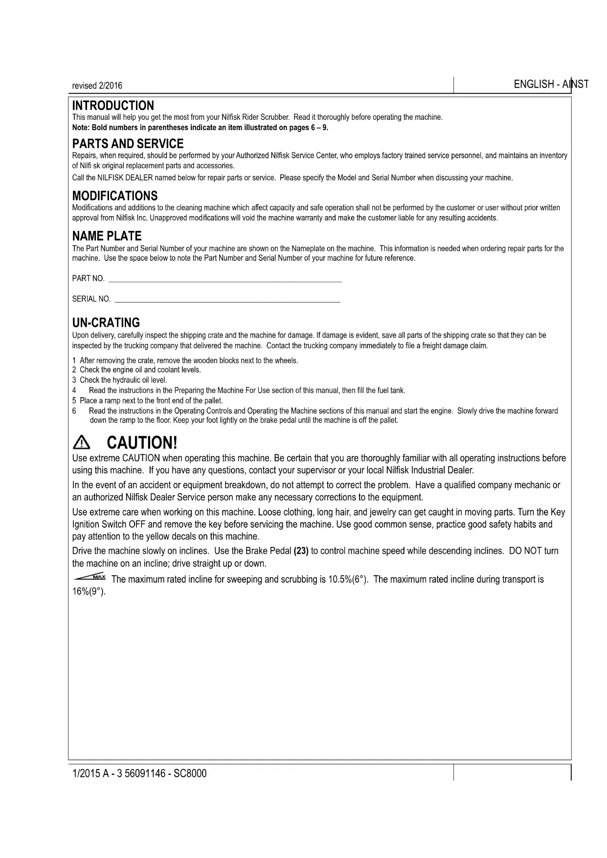
KNOW YOUR MACHINE
As you read this manual, you will occasionally run across a bold number or letter in parentheses - example: (2). These numbers refer to an item shown on these pages unless otherwise noted. Refer back to these pages whenever necessary to pinpoint the location of an item mentioned in the text.
1 Operator's Seat
2 Solution Tank Fill Cover
3 Engine Cover
4 Recovery Tank Cover
5 Engine Air Filter Service Indicator
6 Coolant Overflow Tank
7 Engine Air Filter
8 Engine Cover Latch
9 Recovery Tank Drain Hose
10 Recovery Tank Tilt Out Latch
11 Recovery Tank Tilt Out Grip
12 Left Side Skirt Latch
13 Left Side Skirt
14 Fuel Tank (Diesel tank shown)
15 Fuel Tank Cover Latch
16 Head Light
17 Fuel Tank Cover
18 Operator Seat Adjustment Lever
19 Steering Wheel
20 Double Scrub Skirt Holder
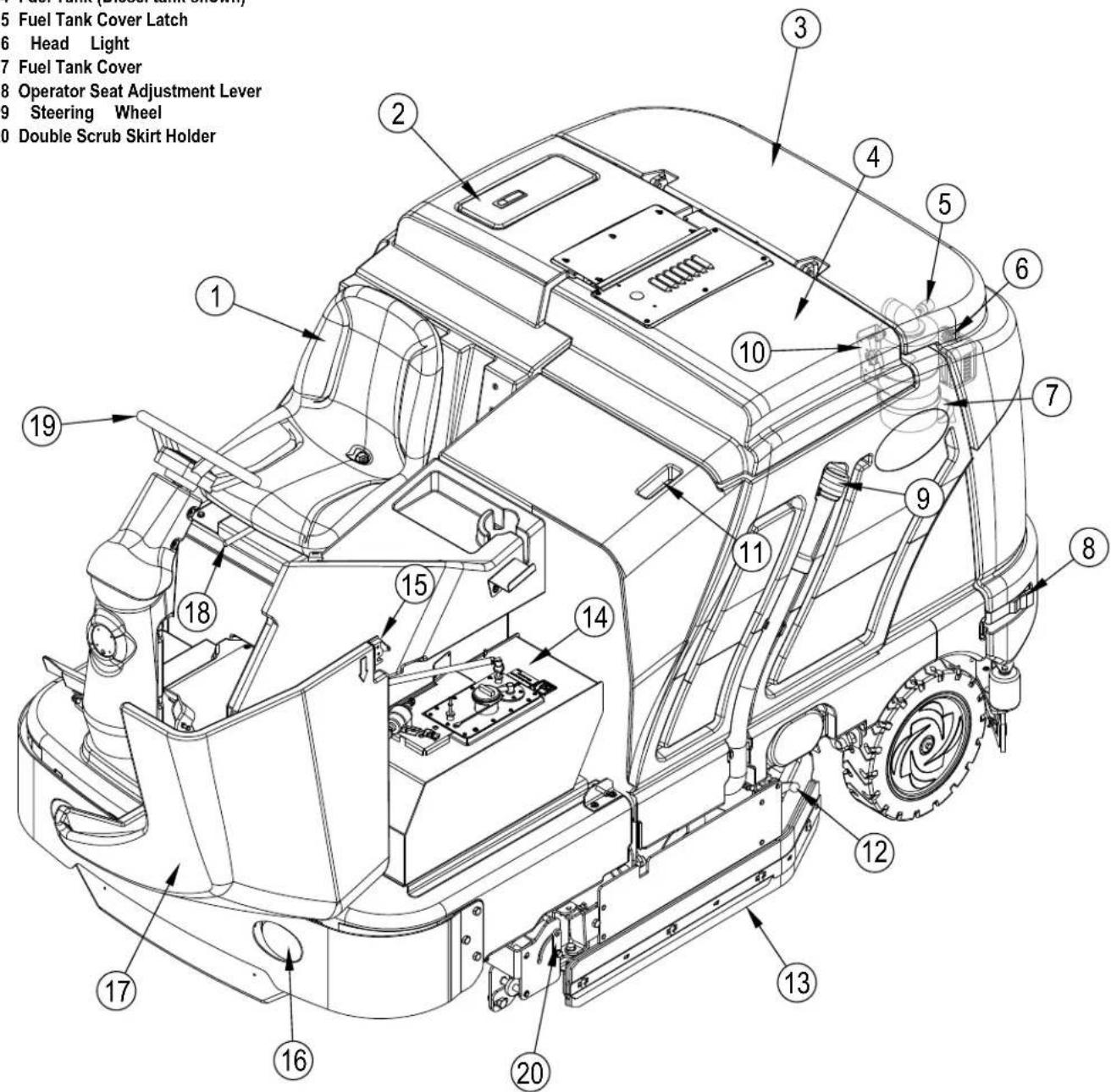
KNOW YOUR MACHINE
24 Detergent Cartridges (EcoFlex models only)
25 Control Panel
26 Circuit Breaker Panel (see Troubleshooting)
27 Steering Wheel Tilt Adjust Lever
28 Brake Pedal / Parking Brake
29 Drive Pedal, Directional/Speed
30 Detergent Cartridge Compartment
31 Right Side Skirt
32 Right Side Skirt Latch
33 Hopper
34 Tow Valve Lever
35 Battery
36 Solution Filter
37 Solution Tank Drain Hose
38 Squeegee Assembly
39 Squeegee Height Adjust Knob
40 Squeegee Mount Wrench
41 Squeegee Tilt Adjust Knob
42 Engine Oil Filter
43 Engine Cover Prop Rod
44 Hydraulic Oil Reservoir Filler Cap
45 Oil Cooler Tilt Out Latch
46 Engine Oil Dipstick
47 Right Scrub Skirt Retainer Knobs
48 Right Scrub Skirt Assembly
49 Engine Oil Drain (under radiator)
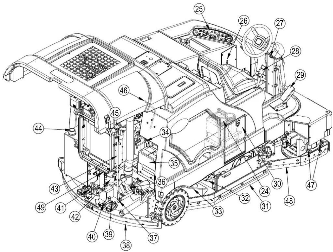
KNOW YOUR MACHINE
50 Key Switch
51 Engine Speed Switch
52 Dust Guard Switch
53 Side Broom/Scrub ON / OFF Switch
53a Side Broom DOWN adjust Switch
53b Side Broom UP adjust Switch
54 Scrub ON / Scrub Mode Select Switch
55 Scrub OFF
56 Solution Switch
56a Solution Flow Decrease Switch
56b Solution Flow Increase Switch
57 EcoFlex Switch
58 Vacuum/Wand Switch (see next page)
59 Horn Switch
60 Extended Scrub Switch (optional / see next page)
61 Detergent System Switch (EcoFlex models only)
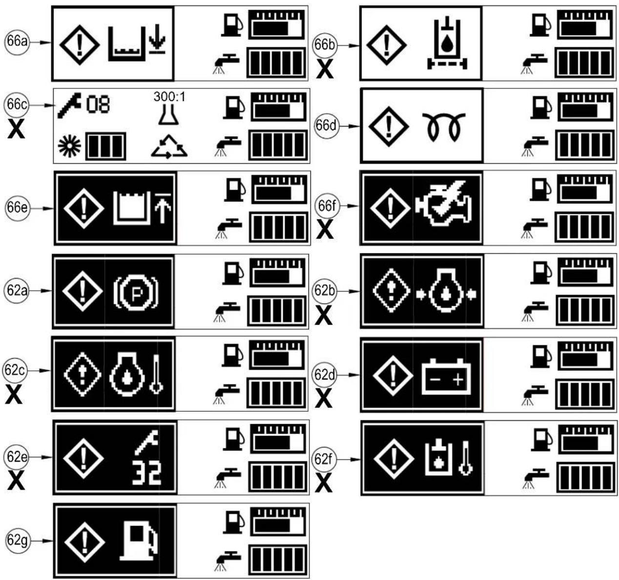
62 Warning Indicator Light (RED)
62a Parking Brake ON
62b Oil Pressure (Diesel)
62c Engine Temp
62d Battery Low
62e Controller Fault
62f Hydraulic Temp
62g Low Fuel
63 Left Turn Signal Switch (optional)
64 Display
64a Scrub Pressure Indicator
64b Hour Meter
64c Detergent Indicator (if so equipped)
64d Fuel Gauge
64e Solution Flow Indicator
64f Extended Scrub Indicator (optional)
65 Right Turn Signal Switch (optional)
66 Attention Indicator Light (YELLOW)
66a Solution Low
66b Hydraulic Filter Plugged
66f Service Engine Soon
67 Emergency Flashers Switch (optional)
68 Head Lights Switch
flowchart
graph TD
    A["64c"] --> B["1234.5"]
    C["64b"] --> B
    D["64a"] --> E[" "]
    F["64f"] --> G[" "]
    H["64d"] --> I[" "]
    J["64e"] --> K[" "]
    L["(scrub 1) press 1 time"] --> M["1234.5"]
    N["(scrub 2) press 2 times"] --> M
    O["(scrub 3) press 3 times"] --> M
    P["Flow Rate 1"] --> Q["1234.5"]
    R["Flow Rate 2"] --> Q
    S["Flow Rate 3"] --> T["1234.5"]
    U["(scrub 1) press 1 time"] --> V["1234.5"]
    W["(scrub 2) press 2 times"] --> V
    X["(scrub 3) press 3 times"] --> V
    Y["60"] --> Z["61"]
    AA["61"] --> AB["62"]
    AC["63"] --> AD["64"]
    AE["65"] --> AF["66"]
    AG["67"] --> AH["68"]
    AI["69"] --> AJ["59"]
    AK["58"] --> AL["57"]
    AM["56b"] --> AN["56a"]
    AO["55"] --> AP["54"]
    AQ["53b"] --> AR["53a"]
    AS["53"] --> AT["52"]
    AU["51"] --> AV["50"]
KNOW YOUR MACHINE
VACUUM / WAND SWITCH (58)
See Vac Wand Kit Instruction Sheet form number 56040944.
EXTENDED SCRUB SWITCH (60)
See Extended Scrub Kit Instruction Sheet form number 56040945.
IF ANY OF THE WARNING / ATTENTION ICONS MARKED(X) BELOW ARE DISPLAYED PLEASE CONTACT YOUR NILFISK AUTHORIZED SERVICE CENTER.
flowchart
graph TD
    A["66a"] --> B["Warning icon"]
    B --> C["Storage unit"]
    C --> D["Storage unit"]
    D --> E["Warning icon"]
    E --> F["Warning unit"]
    F --> G["Storage unit"]
    G --> H["Storage unit"]
    H --> I["Storage unit"]
    I --> J["Storage unit"]
    J --> K["Storage unit"]
    K --> L["Storage unit"]
    L --> M["Storage unit"]
    M --> N["Storage unit"]
    N --> O["Storage unit"]
    O --> P["Storage unit"]
    P --> Q["Storage unit"]
    Q --> R["Storage unit"]
    R --> S["Storage unit"]
    S --> T["Storage unit"]
    T --> U["Storage unit"]
    U --> V["Storage unit"]
    V --> W["Storage unit"]
    W --> X["Storage unit"]
    X --> Y["Storage unit"]
    Y --> Z["Storage unit"]
    Z --> AA["Storage unit"]
    AA --> AB["Storage unit"]
    AB --> AC["Storage unit"]
    AC --> AD["Storage unit"]
    AD --> AE["Storage unit"]
    AE --> AF["Storage unit"]
    AF --> AG["Storage unit"]
    AG --> AH["Storage unit"]
    AH --> AI["Storage unit"]
    AI --> AJ["Storage unit"]
    AJ --> AK["Storage unit"]
    AK --> AL["Storage unit"]
    AL --> AM["Storage unit"]
    AM --> AN["Storage unit"]
    AN --> AO["Storage unit"]
    AO --> AP["Storage unit"]
    AP --> AQ["Storage unit"]
    AQ --> AR["Storage unit"]
    AR --> AS["Storage unit"]
    AS --> AT["Storage unit"]
    AT --> AU["Storage unit"]
    AU --> AV["Storage unit"]
    AV --> AW["Storage unit"]
    AW --> AX["Storage unit"]
    AX --> AY["Storage unit"]
    AY --> AZ["Storage unit"]
    AZ --> BA["Storage unit"]
    BA --> BB["Storage unit"]
    BB --> BC["Storage unit"]
    BC --> BD["Storage unit"]
    BD --> BE["Storage unit"]
    BE --> BF["Storage unit"]
    BF --> BG["Storage unit"]
    BG --> BH["Storage unit"]
    BH --> BI["Storage unit"]
    BI --> BJ["Storage unit"]
    BJ --> BK["Storage unit"]
    BK --> BL["Storage unit"]
    BL --> BM["Storage unit"]
    BM --> BN["Storage unit"]
    BN --> BO["Storage unit"]
    BO --> BP["Storage unit"]
    BP --> BQ["Storage unit"]
    BQ --> BR["Storage unit"]
    BR --> BS["Storage unit"]
    BS --> BT["Storage unit"]
    BT --> BU["Storage unit"]
    BU --> BV["Storage unit"]
    BV --> BW["Storage unit"]
    BW --> BX["Storage unit"]
    BX --> BY["Storage unit"]
    BY --> BZ["Storage unit"]
    BZ --> CA["Storage unit"]
    CA --> CB["Storage unit"]
    CB --> CC["Storage unit"]
    CC --> CD["Storage unit"]
    CD --> CE["Storage unit"]
    CE --> CF["Storage unit"]
    CF --> CG["Storage unit"]
    CG --> CH["Storage unit"]
    CH --> CI["Storage unit"]
    CI --> CJ["Storage unit"]
    CJ --> CK["Storage unit"]
    CK --> CR["Storage unit"]
    CR --> CS["Storage unit"]
    CS --> CT["Storage unit"]
    CT --> CU["Storage unit"]
    CU --> CV["Storage unit"]
    CV --> CW["Storage unit"]
    CW --> CX["Storage unit"]
    CX --> CY["Storage unit"]
    CY --> CZ["Storage unit"]
    CZ --> DA["Storage unit"]
    DA --> DB["Storage unit"]
    DB --> DC["Storage unit"]
    DC --> DD["Storage unit"]
    DD --> DE["Storage unit"]
    DE --> DF["Storage unit"]
    DF --> DG["Storage unit"]
    DG --> DH["Storage unit"]
    DH --> DI["Storage unit"]
    DI --> DJ["Storage unit"]
    DJ --> DK["Storage unit"]
RAISING THE MACHINE
CAUTION!
Never work under a machine without safety stands or blocks to support the machine.
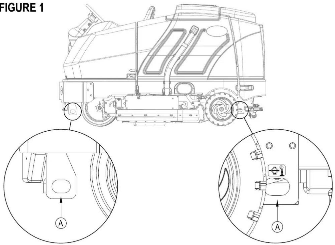
- When raising the machine, do so at designated locations - see Tie Down / Lift Point Locations (A) in Figure 1.
TRANSPORTING THE MACHINE
CAUTION!
Before transporting the machine on an open truck or trailer, make sure that . . .
- All access doors are latched securely.
• The machine is tied down securely - see Tie Down / Lift Point Locations (A) in Figure 1.
• The machine Parking Brake (28) is set.
TOWING OR PUSHING A DISABLED MACHINE
CAUTION!
The machine's drive propelling pump is manufactured with an adjustable tow valve. This valve prevents damage to the hydraulic system when the machine is being towed/pushed short distances without use of the engine.
The tow valve is controlled by the Tow Valve Lever (34) which is accessed by opening and propping the Engine Cover (3). Pull The Tow Valve Lever (34) out; this disengages the hydrostatic lock between the motor and pump.
The drive wheel may be damaged if the machine is towed with the valve in the normal working position (Tow valve lever (34) pushed OUT). Note: if the tow valve is left in free-wheeling position (Tow valve lever (34) pushed IN) the hydraulic pump may not propel the machine forward or reverse. If the tow valve is engaged or partially engaged the vehicle may not operate at full speed. Continuous operation under this conditions can cause overheating and permanent damage to the hydrostatic drive system. Do not tow or push the machine faster than a normal walking pace (2-3 mph / (3-4 km/hr) and for short distances only (300 feet / 100 meters) or serious damage to the hydrostatic drive motor may occur. If the machine is to be moved long distances the front drive wheel needs to be raised off the floor and placed on a suitable transport dolly.
PRE-OPERATIONAL CHECKLIST
Before Each Use:
* Inspect the machine for damage, oil or coolant leaks.
* Squeeze the rubber dust cup on the Engine Air Filter (7) to release built-up dust.
* Check the engine coolant level (6).
* Check the engine oil level (46).
* Check the hydraulic oil level (44).
* Check the Fuel Gauge (64d) on the diesel models.
* Check the Fuel Gauge located on the LP tank for LPG model.
* Check the Air Filter Service Indicator (5).
In the Driver's Seat:
* Be sure that you understand the operating controls and their functions.
* Adjust the seat to allow easy reach of all controls.
* Insert the Master Key and turn the Ignition Key Switch (50) to the ON position. Check for proper operation of the Horn (59), Hour Meter (64b) and Headlights (68). Turn the Ignition Key Switch (50) OFF.
* Check the Brake Pedal (28). The pedal should be firm and should not go all the way down. The latch should hold the pedal when applied. (Report all defects immediately to service personnel).
Plan Your Cleaning in Advance:
* Arrange long runs with a minimum of stopping or starting.
* Allow 2-3" (5.08-7.62cm) of scrub path overlap to ensure complete coverage.
* Avoid making sharp turns, bumping into posts, or scraping the side of the machine.
HYDRAULIC OIL
Open and prop the Engine Cover (3) to access the hydraulic oil reservoir. Remove the Fill Cap (44) from the tank and look to the bottom of the filler screen. If the oil level is below the bottom of the filler screen, add oil (see below for correct type) until the bottom of the filler screen is covered (oil level should not be higher than 1/2" (12.7mm) above the bottom of the filler screen). Change the oil if major contamination from a mechanical failure occurs.
MACHINE SERIAL NUMBER OIL TYPE
Before serial number 10 00068541 SAE 10W30 motor oil
After serial number 1000068540 ISO 32 all-season hydraulic oil
ENGINE OIL - LPG
Check the engine oil level when the machine is parked on a level surface and the engine is cool. Change the engine oil after the first 35 hours of operation and every 150 hours after that. Use any SF or SG rated oil meeting API specifications and suited to seasonal temperatures. Refer to the Engine System section for oil capacities and additional engine specifications. Replace the oil filter with every oil change.
TEMPERATURE RANGE
Above 60° F (15° C)
Below 60° F (15° C)
OIL WEIGHT
SAE 10W-30
SAE 5W-30
ENGINE OIL - DIESEL
Check the engine oil level when the machine is parked on a level surface and the engine is cool. Change the engine oil after the first 35 hours of operation and every 150 hours after that. Use CF, CF-4 or CG-4 oil meeting API specifications and suited temperatures (*important reference the oil/fuel type note below for further diesel oil recommendations). Refer to the Engine System section for oil capacities and additional engine specifications. Replace the oil filter with every oil change.
TEMPERATURE RANGE
Above 77 °F (25 °C)
32 °F to 77 °F (0 °C to 25 °C)
Below 32 °F (0 °C)
OIL WEIGHT
SAE 30 or 10W-30
SAE 20 or 10W-30
SAE 10W or 10W-30
\* Diesel Lubricating Oil Note:
With the emission control now in effect, the CF-4 and CG-4 lubricating oils have been developed for use with a low-sulfur fuel used in on-road vehicle engines. When an off-road vehicle engine runs on a high-sulfur fuel, it is advisable to employ the CF, CD or CE lubricating oil with a high total base number. If the CF-4 or CG-4 lubricating oil is used with a high-sulfur fuel, change the lubricating oil at shorter intervals.
- Lubricating oil recommended when a low-sulfur or high-sulfur fuel is employed.
| Lubricating Oil class\Fuel | Low sulfur (0.5 % ≥) | High sulfur | Remarks |
| CF | O | O | TBN ≥ 10 |
| CF-4 | O | X | |
| CG-4 | O | X |
O : Recommended
X : Not recommended
PRE-OPERATIONAL CHECKLIST ENGINE COOLANT
CAUTION!
Do not remove the radiator cap when the engine is hot.
To check the engine coolant level, open and prop the Engine Cover (3) and observe the coolant level on the Coolant Recovery Tank (6). If the level is low add automotive type anti-freeze appropriately diluted for the environment. Clean the radiator and oil cooler exteriors by washing with low-pressure water or using compressed air every 30 hours. Service Note: The oil cooler tips out for easy cleaning.
ENGINE AIR FILTER
Check the Air Filter Service Indicator (5) before each use of the machine. Do not service the air filter unless the red flag is visible in the service indicator.
CAUTION!
When servicing the engine air filter elements, use extreme care to prevent loose dust from entering the engine. Dust can severely damage the engine.
The engine air filter contains a Primary (outer) and a Safety (inner) filter element. The Primary Element may be cleaned twice before being replaced. The Safety Element should be replaced every third time that the Primary Filter Element is replaced. Never attempt to clean the Inner Safety Element.
To clean the Primary Filter Element, unsnap the 2 clips at the end of the air filter and remove the end housing. Pull the primary element out. Clean the element with compressed air (maximum pressure 100 psi) or wash it with water (maximum pressure 40 psi). DO NOT put the element back into the canister until it is completely dry.
FUEL
WARNING!
• ALWAYS STOP THE ENGINE BEFORE FILLING THE FUEL TANK.
• DO NOT SMOKE WHILE FILLING THE FUEL TANK.
• FILL THE FUEL TANK IN A WELL-VENTILATED AREA.
• DO NOT FILL THE FUEL TANK NEAR SPARKS OR OPEN FLAME.
- USE ONLY THE FUEL SPECIFIED ON THE FUEL TANK DECAL.
On machines with diesel engines, a decal near the Fuel Tank (14) filler neck shows the proper fuel to use in the machine. Before removing the cap from the tank, wipe all dust and dirt from the cap and from the top of the tank to keep the fuel as clean as possible.
On machines with propane engines, a decal near the tank gives specific information about the proper type of tank to be used on the machine.
DIESEL ENGINE
Fill the tank with Number 2 Diesel Fuel if the machine will be used in an area where the temperature is 30^ Fahrenheit (0° Celsius) or higher. Use Number 1 Diesel Fuel if the machine will be used in an area where the temperature is below 30^ Fahrenheit (0° Celsius).
NOTE: If the diesel machine runs out of fuel completely, the fuel system must be bled before the engine can be re-started. To avoid this situation, fill the fuel tank when the fuel gauge indicates 1/4 tank. Fuel tank capacity is 11 gallons (42 liters).
LPG ENGINE
Mount a standard 33 lb. liquid withdrawal propane tank on the machine, connect the fuel hose and open the shutoff valve on the tank. Wear gloves when connecting or disconnecting the fuel hose. Shut the propane tank service valve OFF when the machine is not in use.
The machine shall be inspected by a qualified person regularly, in particular regarding the LPG container and their connections, as required for safe operation by regional or national regulations.
INSTALL THE BRUSHES
CAUTION!
Turn the key switch off (O) and remove the key, before changing the brushes, and before opening any access panels.
1 Make sure the Scrub Deck is in the RAISED position, the Key Switch (50) is off (O) and the Parking Brake (28) is set.
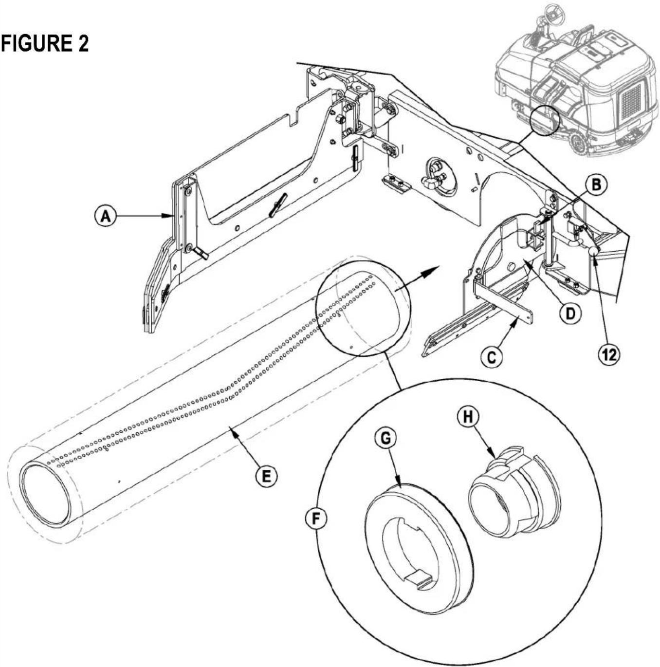
2 See Figure 2. Push down on the Side Skirt Latch (12 or 32) and swing the Skirt Assy (A) open as shown.
3 Lift up on Latch (B), swing Lever (C) out and pull to open the Idler Assembly (D).
4 Slide the Brush (E) into the housing, lift slightly, push and turn until it seats. NOTE: Figure 2 shows a closeup view (F) of the Brush Lugs (G) and the Brush Drive Hub (H).
5 Swing the Idler Assembly (D) closed while holding Lever (C) at a 90 degree angle to the Idler.
6 Once the Idler Assembly (D) is closed, push Lever (C) in until Latch (B) can be slid back down in front of it.
7 Push down on the Side Skirt Latch (12 or 32), swing the Skirt Assy (A) closed and release the Latch.
NOTE: Refer to this section when rotating (flipping end-to-end) brushes according to the maintenance schedule.
FILLING THE SOLUTION TANK
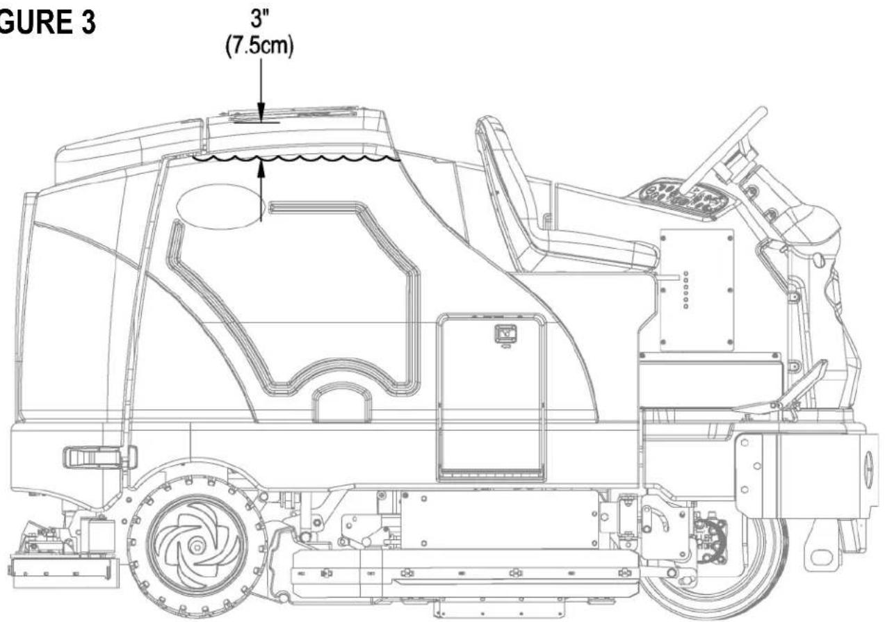
See Figure 3. Fill the solution tank with a maximum of 100 gallons (378.54 Liters) of cleaning solution. Do not fill the solution tank above 7.5 cm (3 inches) from the bottom of the Solution Fill (2). The solution should be a mixture of water and the proper cleaning chemical for the job. Always follow the dilution instructions on the chemical container label. NOTE: EcoFlex machines can either be used conventionally with detergent mixed in the tank or the detergent dispensing system can be used. When using the detergent dispensing do not mix detergent in the tank, plain water should be used.

CAUTION!
Use only low-foaming, non-flammable liquid detergents intended for machine application. Water temperature should not exceed 130 degrees Fahrenheit (54.4 degrees Celsius)
FIGURE 3
The SC8000 is a rider-type automatic floor scrubbing machine. It is designed to lay down cleaning solution, scrub the floor, and vacuum dry all in one pass.
The controls on the SC8000 were designed with one touch operation in mind. For single pass scrubbing the user can simply depress one switch and all scrub functions on the machine will be activated.
NOTE: Bold numbers in parentheses indicate an item illustrated on pages 6-9.
NOTE!: MAKE SURE THE FOOT PEDAL IS IN THE NEUTRAL POSITION. THE ENGINE WILL NOT CRANK IF THE FOOT PEDAL IS NOT IN NEUTRAL. EITHER THE SEAT SWITCH MUST BE CLOSED OR THE BRAKE ENGAGED BEFORE THE ENGINE WILL START.
STARTING THE DIESEL ENGINE
1 Turn the key switch (50) clockwise to the RUN (ON) position. The glow plugs will activate for 10 seconds as indicated by the attention indicator (66) and the glow plug icon (66d) on the display. If the engine is already warm, turn the key switch to the start position to crank the engine. If the engine is cold, wait for the attention indicator and glow plug icon to turn off before cranking the engine. The engine should start immediately. If the engine does not start within 15 seconds release the key, wait for approximately one minute and repeat the above steps.
2 Let the engine run at IDLE speed for five minutes before using the machine.
3 Press the Engine Speed Switch (51) once to switch to "RUN" speed and move the machine around for two to three minutes at slow speed to warm up the hydraulic system.
STARTING THE LPG ENGINE
1 Open the service valve on the LP fuel tank.
2 Turn the Ignition Key Switch (50) clockwise to the START position and release it as soon as the engine starts. If the engine does not start after cranking for 15 seconds, release the key, wait for 1 minute, then try again.
3 Let the engine run at "IDLE" speed for 5 minutes before using the machine.
4 Push the Engine Speed Switch (51) once to switch to "RUN" speed and move the machine around for 2 or 3 minutes at a slow speed to warm up the hydraulic system.
ALWAYS operate the machine with the Engine Speed Switch at run throttle. Use the Drive Pedal (29) not the Engine Speed Switch (51) to control the speed of the machine. The speed of the machine will increase as the pedal is pushed closer to the floor. Do not press the Drive Pedal (29) until the engine has started.
NOTE!: If the operator leaves the seat without setting the brake, the engine will be turned off.
Engine Speed Switch (51):
There are three engine speed settings that can be selected by the engine speed switch (51) on the control panel.
1 "Idle" (1200 RPM – LPG) (1300 RPM – Diesel). Use for warm up and cool down. The engine speed switch light will be off.
2 "Run" (2200 RPM). Use for transporting and most scrubbing operations. The engine speed light will be on.
3 "Maximum" (2400 RPM). Use only for heavy engine load situations such as heavy scrubbing on inclines. The engine speed light will be on.
4 To select between Idle and Run press and release the engine speed switch.
5 To select the Maximum speed, first set the speed to Run. Then press and hold the engine speed switch for 2 seconds. To go back to Run speed, press the switch again.
6 The SC8000 has an automatic idle feature that will reduce the engine speed to idle when the foot pedal (29) has been in the neutral position for 20 seconds or more. The selected engine speed will automatically resume when the foot pedal is moved from neutral. If the engine speed switch (51) is pressed while in idle-override, the automatic idle feature will be temporarily disabled until the next time the foot pedal is moved from the neutral position. This can be useful during troubleshooting or if it is desired to let the machine run at full speed for warming up.
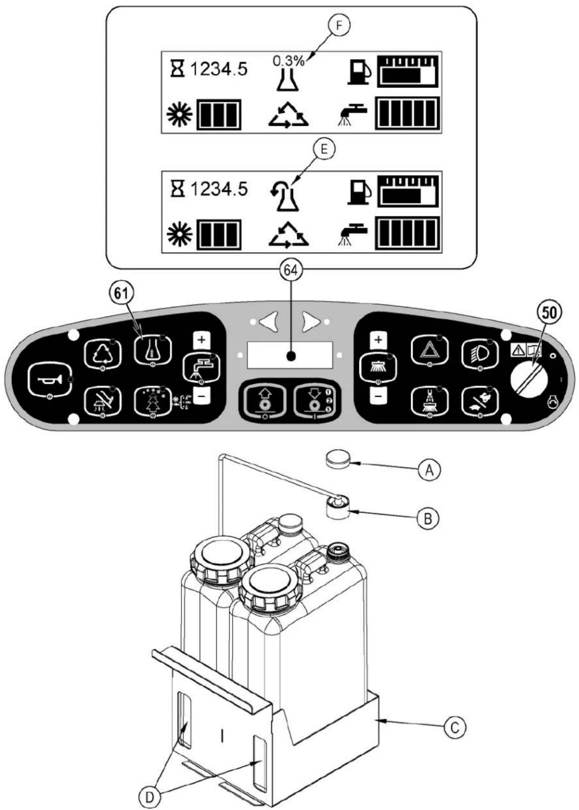
DETERGENT SYSTEM PREPARATION AND USE (ECOFLEX MODELS ONLY)
The Detergent Cartridges (24) are located inside of the Detergent Cartridge Compartment (30). Fill the detergent cartridge with a maximum of 2.2 gallons (8.32 Liters) of detergent. SERVICE NOTE: Remove the detergent cartridge from the detergent box prior to filling to avoid spilling detergent on the machine.
It is recommended that a separate cartridge be used for each detergent you plan to use. The detergent cartridges have a white decal on them so you can write the detergent name on each cartridge to avoid mixing them up. When installing a new cartridge, remove the Cap (A) and place the cartridge in the detergent box. Install the Dry Break Cap (B) as shown.
The system should be purged of previous detergent when switching to a different detergent. SERVICE NOTE: Move machine over floor drain before purging because a small amount of detergent will be dispensed in the process.
To Purge When Changing Chemicals(SCRUB SYSTEM MUST BE OFF):
1 Disconnect and remove the detergent cartridge.
2 Turn the key switch (50) to the RUN (ON) position. Wait a few seconds for the start-up sequence to finish.
3 Press and hold the detergent switch (61) for approximately 2 seconds. Release the switch when the chemical purge icon (E) appears on the display and the indicator on the detergent switch (61) starts flashing. NOTE: Once activated the purge process takes at least 20 seconds. See illustration on next page for Detergent System indicators. Normally one purge cycle is adequate to purge the system.
To Purge Weekly(SCRUB SYSTEM MUST BE OFF):
1 Disconnect and remove the detergent cartridge. Install and connect a Cartridge filled with clean hot water.
2 Turn the key switch (50) to the RUN (ON) position. Wait a few seconds for the start-up sequence to finish.
3 Press and hold the detergent switch (61) for approximately 2 seconds. Release the switch when the chemical purge icon (E) appears on the display and the indicator on the detergent switch (61) starts flashing. NOTE: Once activated the purge process takes at least 20 seconds. See illustration on next page for Detergent System indicators. Normally one purge cycle is adequate to purge the system.
The Detergent Box (C) has Detergent Level Viewing Slots (D) for referencing the amount of detergent remaining in the cartridge(s). When the detergent level is nearing the bottom of this slot it is time to refill or replace the cartridge(s).
Detergent Ratio (SCRUB SYSTEM MUST BE ON):
The default minimum concentration detergent ratio is .04%. The maximum detergent concentration detergent rate may be adjusted by pressing and holding the detergent switch (61) for two seconds. Release the switch once the detergent switch light begins flashing. While the light is flashing, pressing and releasing the detergent switch will cycle through the available percentages (.04%, .05%, .07%, .08%, 1.0%, 1.5%, 2.0%, 3.0%, or 3.8%). Once the desired percentage is displayed on the screen (F), stop and it will lock in after 3 seconds.
- The detergent mixture (F) will always be displayed when the detergent system is on.
Once set, the detergent flow rate automatically increases and decreases with the solution flow rate but the detergent ratio remains the same. If an operator would prefer the flexibility of setting different detergent dilutions ratios for different solution flow rates this specific programming can be found in the service manual. During scrubbing, the detergent system can be turned off at any time by pressing the Detergent ON/OFF Switch (61) to allow scrubbing with water only. No detergent is dispensed until the scrub system is activated and the Drive Pedal (29) pushed forward.
SERVICE NOTE: Follow the "To Purge Weekly" instructions above if the machine is going to be stored for an extended period of time or if you plan to discontinue use of the detergent (EcoFlex) system.
DETERGENT SYSTEM PREPARATION AND USE (ECOFLEX MODELS ONLY)
FIGURE 4
SCRUBBING
WARNING!
Be sure you understand the operator controls and their functions.
While on ramps or inclines, avoid sudden stops when loaded. Avoid abrupt sharp turns. Use low speed down hills.
To Scrub...
Follow the instructions in preparing the machine for use section of this manual. Start the engine following the instructions in the appropriate "Starting the ... Engine" section.
1 See Figure 5. While seated on the machine, adjust the seat and steering wheel to a comfortable operating position using the adjustment controls (18 & 27).
2 Release the Parking Brake (28). To transport the machine to the work area, apply even pressure with your foot on the front of the Drive Pedal (29) to go forward or the rear of the pedal for reverse. Vary the pressure on the foot pedal to obtain the desired speed.
3 Press the Solution Switch (56) and hold for 5 seconds to pre-wet the floor. NOTE: This will help prevent scarring of the floor surface when starting to scrub with dry brushes. This must be done prior to pressing the Scrub ON Switch (54).
4 Press the Scrub ON Switch (54) once for Light Scrub (1), twice for Medium Scrub (2) or three times for Heavy Scrub (3) mode. Both the solution flow and detergent (EcoFlex models) flow have 3 presets that coincide with the 3 scrub modes (see Display Panel (64)). The right side scrub brush pressure is also affected when pressing this switch.
NOTE: The solution flow rate can be overridden simply by pressing the Solution Flow Decrease or Increase Switches (56a / 56b). Any subsequent scrub pressure adjustments will reset the solution flow rate to correspond with the scrub pressure.
NOTE: The scrub, solution, vacuum, detergent (EcoFlex models) and side broom(s) / brush systems are automatically enabled when the Scrub ON Switch (54) is pressed. Any individual system can be turned OFF or back ON by simply pressing its switch at any time during scrubbing. If you have installed the Extended Scrub Kit, it will not be automatically activated. You must press the Extended Scrub Switch (60) to activate this system. The Extended Scrub system will not turn ON until the water level in the recovery tank reaches a certain level and the clean solution has been used up.
5 When the Scrub ON Switch (54) is selected, the brushes, squeegee and side broom(s) / brush are automatically lowered to the floor. The scrub, solution, vacuum, detergent (EcoFlex models) and side broom(s) / brush systems all start when the Drive Pedal (29) is activated.
NOTE: When operating the machine in reverse the squeegee automatically raises and the solution flow will stop.
6 Begin scrubbing by driving the machine forward in a straight line at a normal walking speed and overlap each path by 2-3" (5.08-7.62cm). Adjust the machine speed and solution flow when necessary according to the condition of the floor.
The side broom height can be adjusted by pressing the Side Broom DOWN and UP Switches (53a/53b). The side broom(s) will return to the last used position each time the sweep system is turned on. The side brooms have a misting function (Dust Guard) (52) for use in dusty conditions. NOTE: The "Dust Guard" (52) comes on automatically with the Side Brooms (53) but can be turned OFF by pressing (52). NOTE: If equipped with Extended Scrub, the "Dust Guard" will shut off when the machine runs out of clean solution.
CAUTION!
To avoid damaging the floor, keep the machine moving while the brushes are turning (the brushes will turn OFF after a 2 second delay when the drive pedal is placed in the neutral position).
Raise scrub deck and side scrub brush, if so equipped, when crossing speed bumps. Do not attempt to operate the scrub deck or side brush in the down position when crossing speed bumps. Hydraulic pressure pushes down on the brushes and attempting to operate in the scrub mode over a speed bump can cause damage to the machine.
7 When scrubbing, check behind the machine occasionally to see that all of the waste water is being picked up. If there is water trailing the machine, you may be dispensing too much solution, the recovery tank may be full, or the squeegee tool may require adjustment.
8 The machine defaults to the EcoFlex cleaning mode (if detergent is installed) (EcoFlex Switch Indicator is lit) conserving solution and detergent. Press the EcoFlex Switch (57) to override the EcoFlex cleaning mode and temporarily increase scrub pressure, solution flow and the detergent percentage. This will cause the indicator to flash for one minute, solution flow rate will increase to the next level, scrub pressure will increase to the next level and the detergent ratio will increase to the next higher percentage from the last one used (detergent system will be turned on if it was off).
NOTE: Pressing and holding the EcoFlex Switch (57) for 2 seconds disables the EcoFlex system. The only way to re-enable is to push the EcoFlex Switch (57) again. Cycling the Key Switch (50) does not re-enable the system. The EcoFlex system will only function if the Scrub System (54) has been enabled.
9 For extremely dirty floors, a one-pass scrubbing operation may not be satisfactory and a "double-scrub" operation may be required. This operation is the same as a one-pass scrubbing except on the first pass the squeegee is in the up position (press the Vacuum Switch (58) to raise the squeegee). This allows the cleaning solution to remain on the floor to work longer. The Side Skirts (13 & 31) can also be raised for double scrubbing if needed with the Skirt Holders (20). The final pass is made over the same area, with the squeegee and skirts lowered to pick up the accumulated solution.
10 The recovery tank has a float switch that causes ALL systems to turn OFF except the drive system when the recovery tank is full. When this float switch is activated, the recovery tank must be emptied. The machine will not pick up water or scrub with the float switch activated.
NOTE: The Attention Indicator Light (66) will light up YELLOW and the Recovery Full Icon (66e) will display when the float switch is activated. If the control repeatedly gives a full indication when the tank is not full check to make sure the float moves freely.
11 When the operator wants to stop scrubbing, press the Scrub OFF Switch (55) once. This will automatically stop the scrub brushes, side broom(s) / brush, solution flow and detergent flow. The scrub deck and side broom(s) / brush will raise up. The squeegee will raise up after a brief delay and the vacuum will stop after a brief delay (this is to allow any remaining water to be picked up without turning the vacuum back on).
12 Drive the machine to a designated waste water "DISPOSAL SITE" and empty the recovery tank. To empty, pull the Drain Hose (9) from its storage area, then remove the plug (hold the end of the hose above the water level in the tank to avoid sudden, uncontrolled flow of waste water). The Recovery Tank Drain Hose (9) can be squeezed to regulate the flow. Refill the solution tank and continue scrubbing.
NOTE: Make sure the Recovery Tank Cover (4) and the Recovery Tank Drain Hose (9) cap are properly seated or the machine will not pick-up water correctly.
SERVICE NOTE: Refer to the service manual for optional programmability.
1 When finished scrubbing, press the Scrub Off Switch (55). This will automatically raise, retract and stop all the machine systems (brush, squeegee, vacuum, solution and detergent (EcoFlex models)). Then drive the machine to a service area for daily maintenance and review of other needed service up keep.
2 To empty the solution tank, remove the Solution Drain Hose (37) from its storage clamp. Direct the hose to a designated "DISPOSAL SITE" and remove the cap. Rinse the tank with clean water.
3 To empty the recovery tank, pull the Recovery Tank Drain Hose (9) from its storage area. Direct the hose to a designated "DISPOSAL SITE" and remove the plug (hold the end of the hose above the water level in the tank to avoid sudden, uncontrolled flow of waste water). The Recovery Tank Drain Hose can be squeezed to regulate the flow. Rinse the recovery tank with clean water. Inspect the recovery and vacuum hoses; replace if kinked or damaged.
4 Remove the brushes, remove any string or banding that is wrapped around them, rinse in warm water and stand on end to dry. NOTE: Brushes should be flipped "end for end" and rotated "front to back" daily for longest life.
5 Remove the squeegee, rinse it with warm water and re-install on mount.
6 Remove the Hopper (33) and clean thoroughly. Remove from the right side of the machine by opening the skirt, disconnecting the vacuum hose and then pulling out. NOTE: Reconnect vacuum hose after re-installing.
7 Check the maintenance schedule and perform any required maintenance before storage
SHUTTING DOWN THE DIESEL ENGINE
1 Put all controls to the OFF position.
2 Raise the squeegee, the scrub brushes, and the brooms.
3 Push the Engine Speed Switch (51) to change to "Idle" speed and let the engine idle for 30 seconds.
4 Apply the Parking Brake (28).
5 Turn the Key Ignition Switch (50) OFF and remove the key.
SHUTTING DOWN THE LPG ENGINE
1 Put all controls to the OFF position.
2 Raise the squeegee, the scrub brushes, and the brooms.
3 Turn the service valve on LP gas tank OFF.
4 Push the Engine Speed Switch (51) to change to "Idle" speed and let the engine idle until all the LP gas is dispelled from the line.
5 Apply the Parking Brake (28)
6 Turn the Key Ignition Switch (50) OFF and remove the key.
IMPORTANT NOTE: During normal operation the engine will continue to run for a short period of time (1-3 seconds) after turning the key OFF until all fuel is dispelled from fuel system.
MAINTENANCE SCHEDULE
Keep the machine in top condition by following the maintenance schedule closely. Maintenance intervals given are for average operating conditions. Machines used in severe environments may require service more often.
| MAINTENANCE | ITEM | DAILY | ||||
| Perform the “After Use” maintenance steps X | ||||||
| Check parking brake X | ||||||
| Check engine oil X | ||||||
| *Check / Clean / Rotate & flip the Brushes | X | |||||
| Check filter indicator and lights (hyd & air) | X | |||||
| Check engine coolant level X | ||||||
| Check hydraulic oil level X | ||||||
| Drain / Check / Clean Tanks & Hoses X | ||||||
| Check / Clean the Squeegee X | ||||||
| Clean the Hopper X | ||||||
| Clean the DustGuard system spray nozzles X | ||||||
| Purge Detergent System (EcoFlex only) | X | |||||
| Inspect main scrub head skid plates(replace if worn to 1/8") | X | |||||
| MAINTENANCE ITEM | 15 hrs. | 30 hrs. | 150 hrs. | 300 hrs. | 500 hrs. | 1000 hrs. |
| Inspect and clean the Solution Filter | X | |||||
| Clean radiator and oil cooler | X | |||||
| Side Broom Maintenance | X | |||||
| Clean solution trough | X | |||||
| Inspect scrub housing skirts | X | |||||
| Perform engine maintenance | X | |||||
| Inspect and grease steering rack | X | |||||
| Change the hydraulic “charge” oil filter | X | |||||
| Change reservoir hydraulic oil and filter | X | |||||
| Flush the radiator | X | |||||
| Engine fuel filter(s) lpg | X | |||||
* See "INSTALL THE BRUSHES" section.
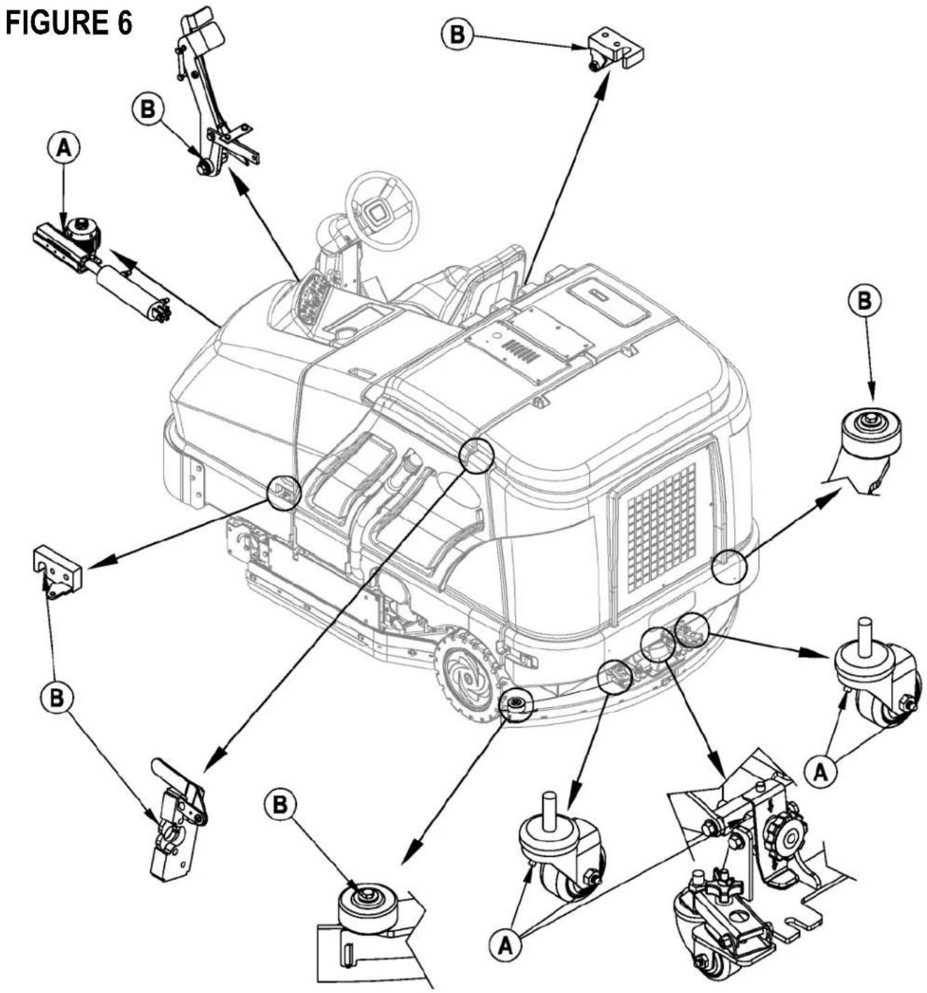
LUBRICATING THE MACHINE - FIGURE 6
Once a month, pump a small amount of grease into each grease fitting on the machine until grease seeps out around the bearings.
Grease fi tting locations (or apply grease to) (A):
• Squeegee Caster Wheel Axle and Pivot
- Steering Rack
- Squeegee mount angle adjustment knob threads
Once a month, apply light machine oil to lubricate the (B):
- Squeegee tool end wheels
- Fuel Tank Cover Latch
• Recovery Tank Latch
- EcoFlex Cover Latch
- Brake Pedal (parking brake) linkage
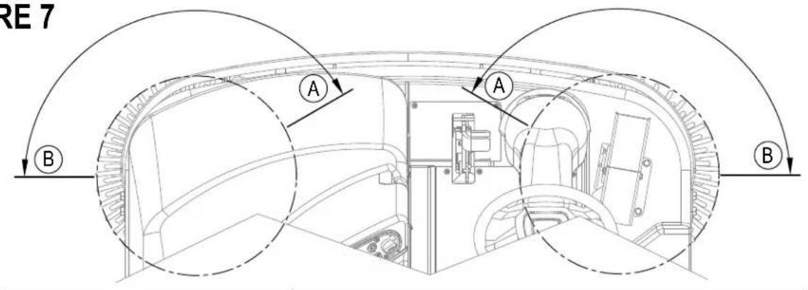
The side broom(s) move dirt and debris away from walls or curbs and into the path of the main brushes. Adjust the side broom(s) so that the bristles are contacting the floor from the (A) to (B) area shown in Figure 7 when the broom is down and running.
To adjust the Side Brooms...
1 The side broom(s) are adjusted simply by pressing either the Side Broom DOWN Switch (53a) or the Side Broom UP Switch (53b). NOTE: Broom setting resumes each time brooms are lowered but adjustment will be needed as brooms wear or are replaced.
NOTE: The machine should be stored with the Side Brooms in the raised position. The Side Brooms should be replaced when the bristles are worn to a length of 3 inches (7.62 cm) or they become ineffective. Side brooms should be replaced in pairs as they are not independently adjustable for proper height.
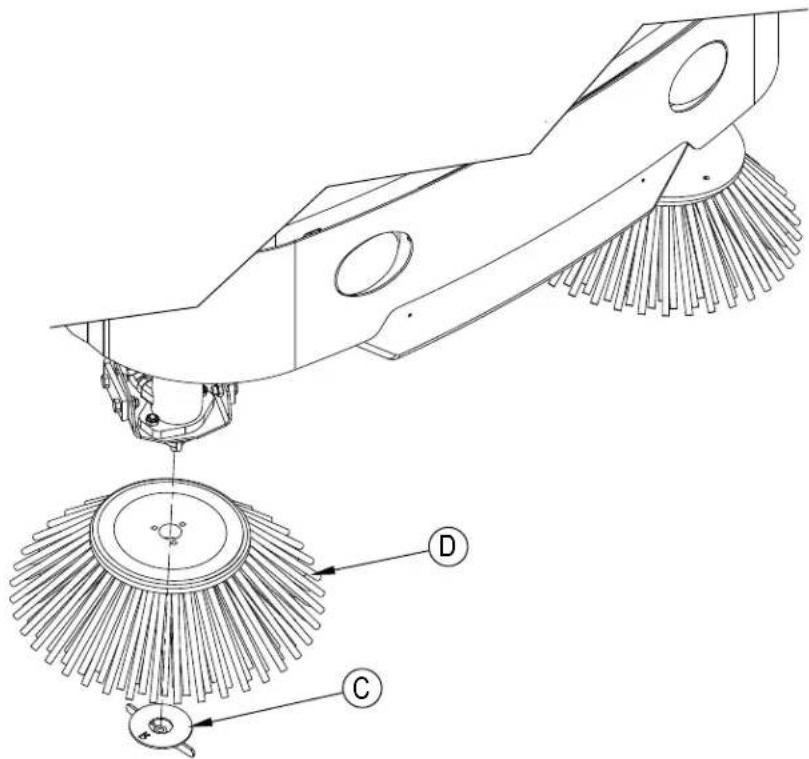
To replace a Side Broom.
1 Raise the Side Broom(s).
2 Remove the large Thumb Nut (C) and remove the Side Broom (D). NOTE: The right side Thumb Nut (C) has right handed threads and the left side Thumb Nut (C) has left handed threads.
3 Install the new broom by sliding it UP onto the shaft and re-install the Thumb Nut (C).
DUSTGUARD NOZZLE CLEANING PROCEDURE
To prevent nozzle plugging remove nozzle(s) after each daily use and soak overnight in clean white vinegar or appropriate calcium/lime remover. To avoid machine downtime best practice is to purchase spare nozzle(s) and replaced those that have just been used with those that have been cleaned. When nozzles can no longer be cleaned effectively replace as necessary.
FIGURE 7
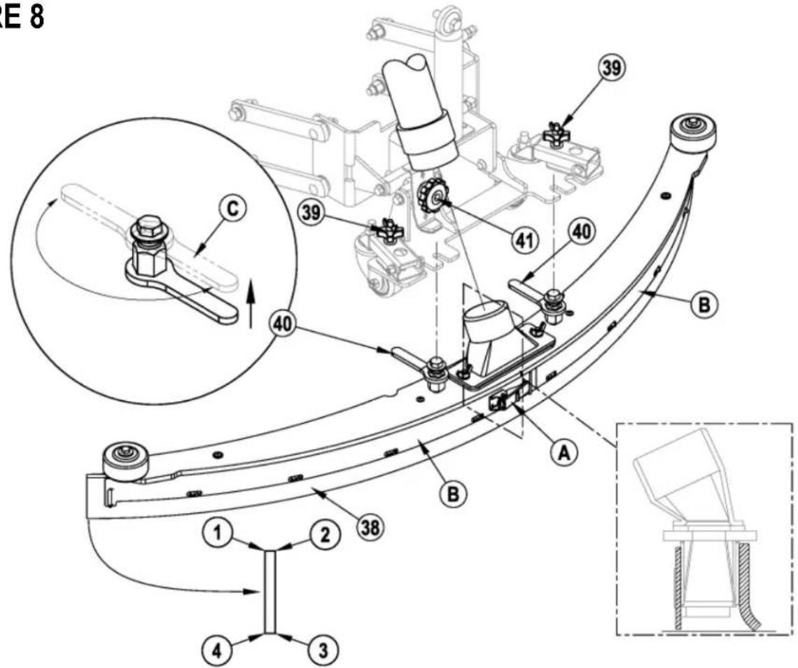
If the squeegee leaves narrow streaks or water, the blades may be dirty or damaged. Remove the squeegee, rinse it under warm water and inspect the blades. Reverse or replace the blades if they are cut, torn, wavy or worn.
To Reverse or Replace the Rear Squeegee Wiping Blade...
1 See Figure 8. Raise the squeegee tool off the floor, then unsnap the Center Latch (A) on the squeegee tool.
2 Remove the Tension Straps (B).
3 Slip the rear blade off the alignment pins.
4 The squeegee blade has 4 working edges as shown below. Turn the blade so a clean, undamaged edge faces toward the front of the machine. Replace the blade if all 4 edges are nicked, torn or worn to a large radius.
5 Install the blade, following the steps in reverse order and adjust the squeegee tilt.
To Reverse or Replace the Front Squeegee Blade..
1 Raise the squeegee tool off the floor, then loosen the (2) Squeegee Mount Wrenches (40) on top of the squeegee and remove the Squeegee tool (38) from the mount.
2 Remove both rear Tension Straps fi rst.
3 Remove all the wing nuts that hold the front blade in place, then remove tension strap and blade.
4 The squeegee blade has 4 working edges as shown below. Turn the blade so a clean, undamaged edge faces toward the front of the machine. Replace the blade if all 4 edges are nicked, torn or worn to a large radius.
5 Install the blade, following the steps in reverse order and adjust the squeegee tilt.
SERVICE NOTE: Depending on the position of the Squeegee Mount Wrenches (40), you may not be able to rotate the wrench far enough to loosen or tighten depending on which you are trying to do. In this case, simply lift UP on the Handle (C) and rotate the wrench in the direction necessary to acquire adequate turning space and then allow the wrench to drop back DOWN into place on the hex. You can then either tighten or loosen as needed.
SQUEEGEE ADJUSTMENT
There are two squeegee tool adjustments possible, angle and height.
Adjusting the Squeegee Angle
Adjust the squeegee angle whenever a blade is reversed or replaced, or if the squeegee is not wiping the floor dry.
1 Park the machine on a flat, even surface.
2 Lower the squeegee, move the machine ahead slightly and adjust the squeegee tilt and height using the Squeegee Tilt Adjust Knob (41) and Squeegee Height Adjust Knobs (39) so that the rear squeegee blade touches the floor evenly across its entire width and is bent over slightly as shown in the squeegee cross section.
FIGURE 8
Turn the key switch off (O) and remove the key, before changing the brushes, and before opening any access panels.
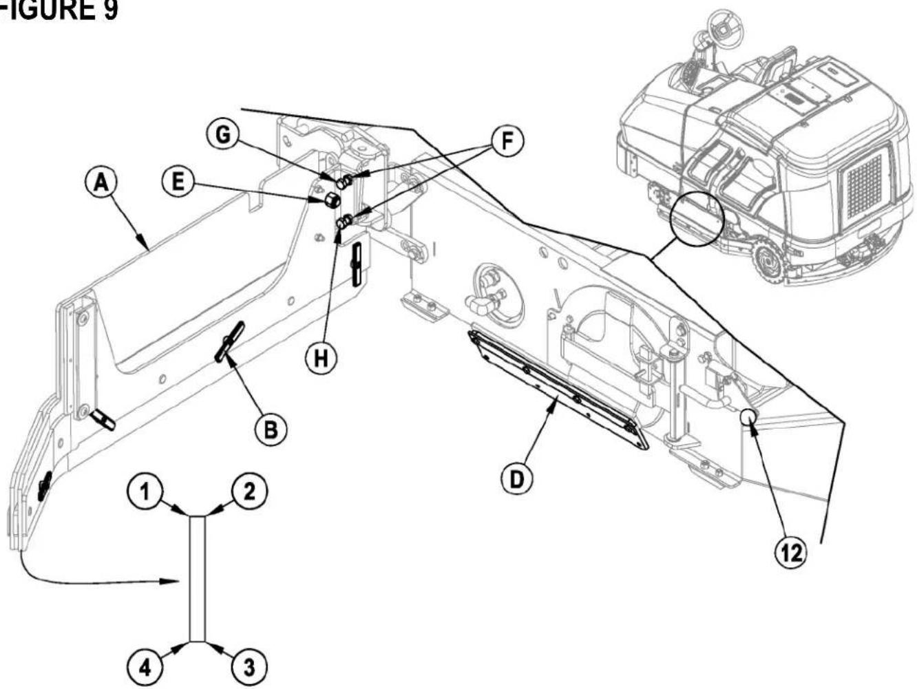
The side skirt's function is to channel the waste water to the squeegee, helping contain the water within the machines cleaning path. During normal use the blades will wear in time.
To reverse or replace the scrub system side skirt(s) ...
1 See Figure 9. Push down on the Side Skirt Latch (12 or 32) and swing the Skirt Assy (A) open as shown.
2 Remove all the hardware that holds the blades to the skirt housings. NOTE: The main blades on each skirt assembly are held on with Tool-less Retainers. Simply loosen the large Wing nuts (B) and then turn the Knobs (C) on the outside of the skirt assembly until they are horizontal and push through the slots. The small inside Blade (D) is held on by (4) screws.
3 The skirt blades have 4 working edges as shown. Turn the blades so a clean, undamaged edge faces toward the center of the machine. Replace the blades as a set if all 4 edges are nicked, torn or worn excessively.
SIDE SKIRT TILT ADJUSTMENT
The side skirt assemblies may periodically need to have their tilt in relation to the floor adjusted.
1 Make sure the scrub deck is in the raised position.
2 To adjust, loosen Nut (E), loosen Nuts (F) and then turn Screws (G & H) as follows. Turn Screw (G) clockwise and Screw (H) counter-clockwise to lower the rear of the skirt assembly. Turn Screw (G) counter-clockwise and Screw (H) clockwise to raise the rear of the skirt assembly.
NOTE: Initial tilt adjustment should be parallel to the floor with the deck raised. Make small adjustments to obtain good blade wiping. Do not lower the rear of the blades too much to where they fold over excessively and cause unneeded blade wear.
FIGURE 9
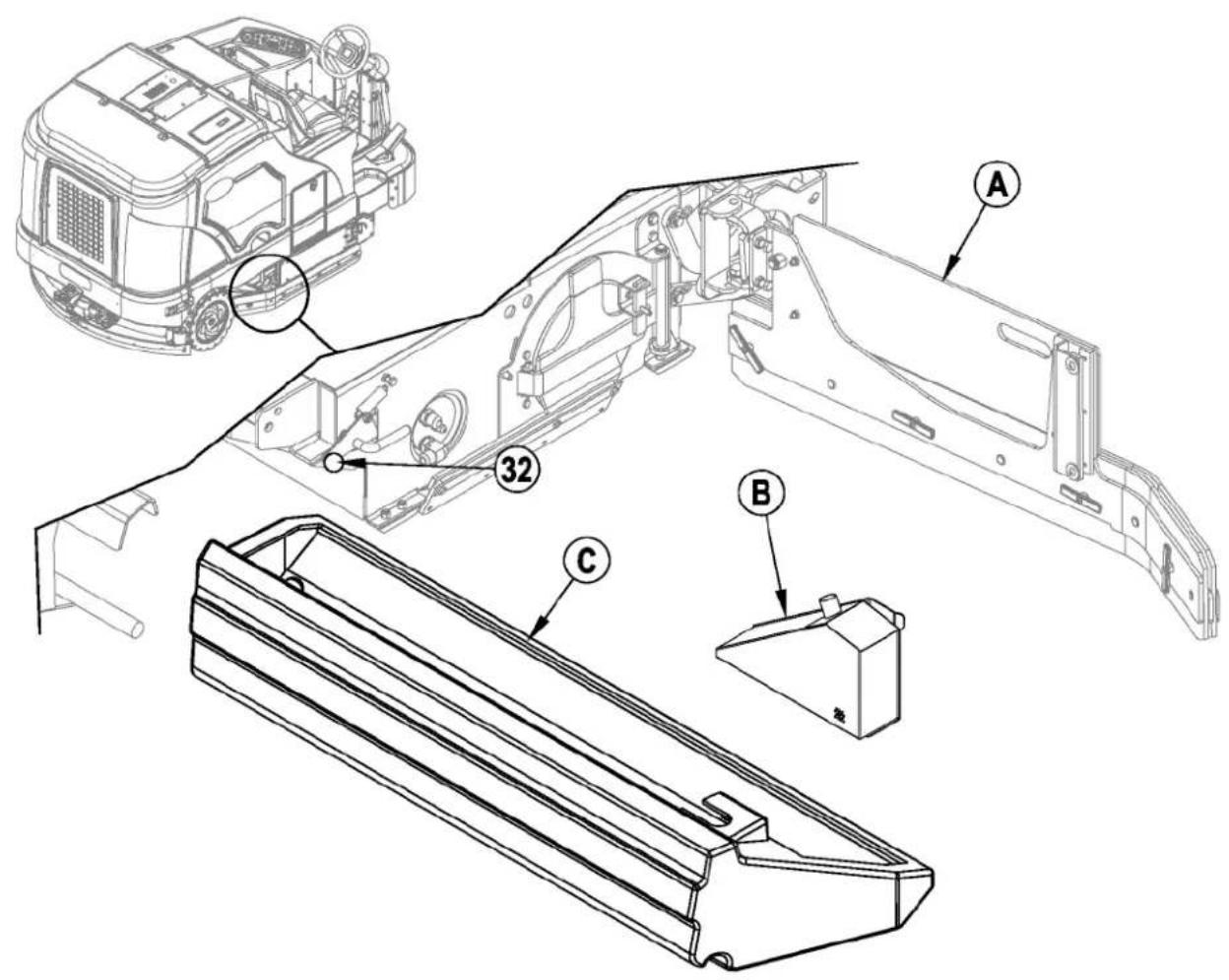
Turn the key switch off (O) and remove the key, before opening any access panels.
1 See Figure 10. Push down on the Right Side Skirt Latch (32) and swing the Skirt Assy (A) open as shown.
2 Disconnect the small vacuum hose from the Screen (B) and slide the entire Hopper (C) out of the machine.
3 Remove the Screen (B) from the Hopper (C) and thoroughly rinse both to clear debris.
FIGURE 10
TROUBLESHOOTING
If the possible causes listed below are not the source of trouble, it is a symptom of something more serious. Contact your Nilfisk Service Center immediately for service.
TRIPPING THE CIRCUIT BREAKERS
The circuit breakers are located on the Circuit Breaker Panel in the operator's compartment; they protect electrical circuits and motors from damage due to overload conditions. If a circuit breaker trips, try to determine the cause.
VACC1 Circuit Breaker (CB1 / 20 Amp) Possible cause may be:
1 Electrical short circuit (have your Nilfisk Service Center or qualified electrician check the machine)
VACC2 Circuit Breaker (CB2 / 20 Amp) Possible cause may be:
1 Electrical short circuit (have your Nilfisk Service Center or qualified electrician check the machine)
VACC3 Circuit Breaker (CB3 / 15 Amp) Possible cause may be:
1 Electrical short circuit (have your Nilfisk Service Center or qualified electrician check the machine)
VACC4 Circuit Breaker (CB4 / 20 Amp) Possible cause may be:
1 Electrical short circuit (have your Nilfisk Service Center or qualified electrician check the machine)
VACC5 Circuit Breaker (CB5 / 10 Amp) Possible cause may be:
1 Electrical short circuit (have your Nilfisk Service Center or qualified electrician check the machine)
Ignition Circuit Breaker (CB 6 / 15 Amp) Possible cause may be:
1 Electrical short circuit (have your Nilfisk Service Center or qualified electrician check the machine)
Once the problem has been corrected, push the button in to reset the circuit breaker. If the button does not stay in, wait 5 minutes and try again. If the circuit breaker trips repeatedly, call your Nilfisk Service Center for service.
VACC1 Circuit Breaker (CB1)
• Right Rear Stop/Turn Lamp
• Left Rear Stop/Turn Lamp
• Right Front Turn Lamp
- Left Front Turn Lamp
- Rear Tail Lamps
- Head Lamps
VACC2 Circuit Breaker (CB2)
• Wash Hose Solution Pump (M8)
• Side Sweep Mist Pump (M5)
VACC3 Circuit Breaker (CB3)
• Side Sweep Lift Actuator Motor (M7)
VACC4 Circuit Breaker (CB4)
• Scrub Brush Solenoid (L4)
• Scrub Pressure Down (L5)
• Scrub Cylinder Lock Solenoid (L6)
• Scrub Pressure Up (L7)
• Side Sweep / Scrub Solenoid (L8)
• Side Scrub Lift Solenoid (L9)
• Main Solution Solenoid Valve (L10)
• Side Scrub Solution Solenoid Valve (L11)
• Extended Scrub Water Solution Solenoid
- Chemical Pump
VACC5 Circuit Breaker (CB5)
• Vacuum Motor Solenoid (L1)
• Squeegee Down Solenoid (L3)
• Squeegee Up Solenoid (L3)
• Main Solution Pump (M4)
• Extended Scrub Pump (M6)
IGN Circuit Breaker (CB6)
- Glow Plug Relay
- Main Power Relay
• Backup Audible Alarm
- Horn
• Engine System (fuel pump and ignition system)
- Dash Board Panel
natural_image
Line drawing of a cleaning or dust cleaning vehicle with no visible text or symbols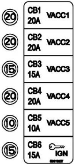
GENERAL MACHINE TROUBLESHOOTING
| Problem Possible Cause Remedy | ||
| Poor water pick-up Worn or torn squeegee | blades Reverse or replace | |
| Squeegee out of adjustment Adjust so blades touch | floor evenly across entire width | |
| Recovery tank full Empty recovery tank | ||
| Recovery tank drain hose leak Secure drain hose cap or replace | ||
| Recovery tank cover gasket leak Replace gasket / Seat cover properly | ||
| Debris caught in squeegee Clean squeegee tool | ||
| Vacuum hose clogged Remove debris | ||
| Using too much solution Reduce flow via control panel solution button | ||
| Poor scrubbing performance Worn brush | Rotate or replace brushes | |
| Wrong brush type | Consult Nilfi sk | |
| Wrong cleaning chemical | Consult Nilfi sk | |
| Moving machine too fast | Slow down | |
| Not using enough solution | Increase flow via control panel solution button | |
| Incorrect detergent ratio | Verify dilution setting if EcoFlex equipped. | |
| Inadequate solution flow or no solution | Solution tank empty | Fill solution tank |
| Solution lines, valves, filter or trough clogged | Flush lines, trough and clean solution filter | |
| Solution turned OFF | Activate flow via control panel solution button | |
| Solution solenoid valve plugged or defective | Clean or replace valve (see service manual) | |
| Machine does not run | Tripped 15 Amp (CB6) circuit breaker | Check for electrical short circuit & reset |
| Main system controller | Check error fault codes (see service manual) | |
| No FWD/REV wheel drive | Parking brake set | Release parking brake |
| Towing valve in wrong position | Set correctly | |
| Tripped circuit breakers | Reset any tripped circuit breakers | |
| Vacuum shuts off and display shows “FULL” when recovery tank is not full | Float does not move freely | Clear any debris, clean float stem to allow for free movement. |
| No Detergent Flow (EcoFlex models only) | Empty detergent cartridge | Fill detergent cartridge |
| Plugged or kinked detergent flow line | Purge system, straighten lines to remove any kinks | |
| Dry seal cap on detergent cartridge not sealed | Reseat dry seal cap | |
| Detergent pump wiring disconnected or backwards | Connect or reconnect wiring | |
ACCESSORIES / OPTIONS
In addition to the standard components, the machine can be equipped with the following accessories/options, according to the machine specific use:
• Brushes with harder or softer bristles
• Recovery Tank Clean Out Kit
- Solution Fill Shutoff Kit • Wash Hose Kit
- Warning Beacon Kit • Brake / Signal Light Kit
- Deluxe Seat Kit • Rear Bumper Kit
• Overhead Guard Kit • Fire Extinguisher Kit
- Extended Scrub Kit • Back-Up Alarm Kit
• Chemical Injection
• Underhood Light Kit
- Vac Wand Kit
- RH Armrest Kit
- Dual Armrest Kit
- Seat Belt Kit
• Overhead Guard Beacon Kit
• Overhead Guard Canopy Kit
- Kit-Debris Tray
- Horn Switch Kit
- Drain Hose Extension
- Roller Bumper Kit
For further information about the above-mentioned accessories, contact an authorized Retailer.
| Material Composition and Recyclability | ||
| Type | % of machine weight | % recyclable |
| Aluminum | 1% | 90% |
| Electrical / motors / engines - misc | 13% | 94% |
| Ferrous metals | 59% | 95% |
| Harnesses / cables | 4% | 80% |
| Liquids | 1% | 100% |
| Plastic - non-recyclable | 2% | 0% |
| Plastic - recyclable | 1% | 90% |
| Polyethylene | 16% | 100% |
| Rubber | 5% | 68% |
TECHNICAL SPECIFICATIONS (as installed and tested on the unit)
| Model | SC8000 1300 LPG | SC8000 1600 LPG | SC8000 1200 LPG | |
| SC8000 1300 D (Diesel) | SC8000 1600 D (Diesel) | |||
| Part No. | 56108124 | 56108126 | 56384395 | |
| 56108125 | 56108127 | |||
| Sound Pressure Level | ||||
| (IEC 60335-2-72: Ed 3 2012, ISO 11201) | dB (A) | 84.5 dB LpA, 3dB KpA | 84.5 dB LpA, 3dB KpA | 84.5 dB LpA, 3dB KpA |
| Sound Power Level | ||||
| (IEC 60335-2-72: Ed 3 2012, ISO 3744) | dB (A) | 104.4 dB LwA | 104.4 dB LwA | 104.4 dB LwA |
| Gross Vehicle Weight | Ibs / kg | 4033 / 1829 | 4311 / 1955 | 4311 / 1955 |
| Transport Weight | Ibs / kg | 3110 / 1410 | 3388 / 1536 | 3388 / 1536 |
| Maximum Wheel Floor Loading (center front) | N/mm2 / psi | 0.48/70 | 0.48/70 | 0.48/70 |
| Maximum Wheel Floor Loading (left rear) | N/mm2 / psi | 0.53/77 | 0.53/77 | 0.53/77 |
| Maximum Wheel Floor Loading (right rear) | N/mm2 / psi | 0.54/79 | 0.54/79 | 0.54/79 |
| Vibrations at the Hand Controls (ISO 5349-1) | m/s2 | 0.80 m/s2 | 0.71 m/s2 | 0.71 m/s2 |
| Vibrations at the Seat (ISO 2631-1) | m/s2 | 0.18 m/s2 | 0.23 m/s2 | 0.23 m/s2 |
| Gradeability | ||||
| Transport | 16% (9°) | 16% (9°) | 16% (9°) | |
| Cleaning | 10.5% (6°) 10.5% (6°) | 10.5% (6°) | ||
ÍNDICE
PÁGINA
CONOZCA SU MÁQUINA
MANTENIMIENTO DE LA BOQUILLA
MANTENIMIENTO DE LA TOLVA DE DESECHOS
¡PRECAUCIÓN!
natural_image
Line drawing of a garbage truck with a circular annotation pointing to the side wheel (no text or symbols present)
CB1 20A
VACC1

CB2 20A
VACC2

CB3 15A
VACC3

CB4 20A
VACC4

CB5 10A
VACC5

CB6 15A

CONHEÇA SUA MÁQUINA
50 Chave de ignição
OPERANDO A MÁQUINA
Para ajustar as vassouras laterais...
MANUTENÇÃO DO RODO
natural_image
Line drawing of a garbage truck with a circular annotation pointing to the side wheel (no text or symbols present)
CB1 20A
VACC1

CB2 20A
VACC2

CB3 15A
VACC3

CB4 20A
VACC4

CB5 10A
VACC5

CB6 15A

APPRENEZ À CONNAITRE VOTRE MACHINE
LISTE DE CONTRÔLE AVANT L'UTILISATION
REMLISSAGE DU RÉSERVOIR DE SOLUTION
FONCTIONNEMENT DE LA MACHINE
ENTRETIEN DE LA RACLETTE
DÉPANNAGE
natural_image
Line drawing of a garbage truck with a circular annotation pointing to the side wheel (no text or symbols present)
CB1 20A
VACC1

CB2 20A
VACC2

CB3 15A
VACC3

CB4 20A
VACC4

CB5 10A
VACC5

CB6 15A

DÉPANNAGE GÉNÉRAL DE LA MACHINE
ACCESSOIRES / OPTIONS
Year of Affixing CE marking: 2013
D Der Unterzeichner bestätigt hiermit dass die oben erwähnten Modelle gemäß den folgenden Richtlinien und Normen hergestellt wurden. Die technische Dokumentation wird vom Hersteller erstellt.
GB The undersigned certify that the above mentioned model is produced in accordance with the following directives and standards. The technical file is compiled by the manufacturer
DK Undertegnede attesterer herved, at ovennævnte model er produceret i overensstemmelse med følgende direktiver og standarder. Den tekniske fil er udarbejdet af fabrikanten.
N Undertegnede attesterer att ovennevnte modell är produsert I overensstemmelse med fölgende direktiv og standarder. Den tekniske filen er opprettet av produsenten.
E El abajo firmante certifica que los modelos arriba mencionados han sido producidos de acuerdo con las siguientes directivas y estandares. El fascículo técnico está redactado por el fabricante
Il sottoscritto dichiara che i modelli sopra menzionati sono prodotti in accordo con le seguenti direttive e standard. Il fascicolo tecnico è redatto dal costruttore.
EST Allakirjutanu kinnitab, et ülalnimetatud mudei on valmistatud kooskõlas järgmiste direktiivide ja normidega. Tehnilise dokumentatsiooni koostab tootja.
LV Ar šo tiek apliecināts, ka augstākminētais modelis ir izgatavots atbilstoši šādām direktīvām un standartiem. Tehnisko aprakstu ir sastādījis ražotājs.
CZ Niže podepsaný stvrzuje, že výše uvedený model byl vyroben v souladu s následujícími směrnicemi a normami. Autorem technického listu je výrobce.
SLO Spodaj podpisani potrjujem, da je zgoraj omenjeni model izdelan v skladu z naslednjimi smernicami in standardi. Spis s tehnično dokumentacijo pripravi izdelovalec.
F Je soussigné certifie que les modèles ci-dessus sont fabriqués conformément aux directives et normes suivantes. Le dossier technique est rédigé par le fabricant.
NL Ondergetekende verzekert dat de bovengenoemde modellen geproduceerd zijn in overeenstemming met de volgende richtlijnen en standaards. Het technische bestand is door de fabrikant samengesteld.
FIN Allekirjoittaia vakuuttaa että yllämainittu malli on tuotettu seuraavien direktiivien ja standardien mukaan. Valmistaja kääntää teknisen tiedoston.
S Undertecknad intygar att ovannämnda modell är producerad i överensstämmelse med följande direktiv och standarder. Den tekniska filen är sammanställd av tillverkaren.
GR Ο κάτωθι υπογεγραμμένος πιστοποιεί ότι η παραγωγή του προαναφερθέντος μοντέλου γίνεται σύμφωνα με τις ακόλουθες οδηγίες και πρότυπα. Το τεχνικό αρχείο συντάσσεται από τον κατασκευαστή.
P A presente assinatura serve para declarar que os modelos supramencionados são produtos em conformidade com as seguintes directivas e normas. A ficha técnica é redigida pelo fabricante.
LT Toliau pateiktu dokumentu patvirtinama, kad minėtas modelis yra pagamintas laikantis nurodytų direktyvų bei standartų. Techninę bylą sudarė gamintojas.
PL Niżej podpisany zaświadcza, że wymieniony powyżej model produkowany jest zgodnie z następującymi dyrektywami I normami. Dokumenty techniczne zostały przygotowane przez producenta.
H Alulírottak igazoljuk, hogy a fent említett modellt a következő irányelvek és szabványok alapján hoztuk létre. A műszaki fájlt a gyártó készítette.
SK Dolu podpísaný osvedčuje, že hore uvedený model sa vyrába v súlade s nasledujúcimi smernicami a normami. Technický súbor vytvoril výrobca.
EC Machinery Directive 06/42/EEC
EC EMC Directive 2004/108/EEC
EN 60335-1, EN 60335-2-72
EN 61000-6-2, EN 55012
This product is declared on our sole responsibility.

natural_image
Abstract wavy line drawing with no text or symbols3.22.2013
Nifik Ikgale. Engineering Director
9435 Winnetka Ave North
Minneapolis, MN 55445 USA
Nilfi sk A/S
Kornmarksvej 1
DK-2605 Brøndby · Denmark
©Nilfisk Incorporated, 2012