
SC2000 - Industrial floor scrubber NILFISK - Free user manual and instructions
Find the device manual for free SC2000 NILFISK in PDF.
| Product type | Industrial scrubber dryer |
| Brand | Nilfisk |
| Model | SC2000 |
| Solution tank capacity | 70 liters |
| Recovery tank capacity | 70 liters |
| Length | 1270 mm |
| Width with squeegee | 720 mm |
| Width without squeegee | 550 mm |
| Height | 1020 mm |
| Cleaning width | 530 mm |
| Weight without batteries | 119 kg (standard model) |
| Maximum weight in working order | 342 kg |
| Power supply | Batteries 24 V (2 x 12 V, 105 Ah Discover) |
| Working autonomy (standard batteries) | 2.5 hours |
| Drive speed | 0 - 6 km/h (variable) |
| Brush motor power | 450 W, 155 rpm |
| Suction system power | 310 W, vacuum 1000 mm H₂O |
| Normal brush pressure | 15 kg |
| Brush pressure with extra pressure | 30 kg |
| Maximum slope during cleaning | 15% |
| Noise level (at operator's ear) | 68 ±3 dB(A) |
| Main functions | Washing and drying of smooth floors, EcoFlex system (optional), silent suction, extra brush pressure |
| Maintenance and cleaning | Daily cleaning of squeegee, brush, tanks, draining EcoFlex system, checking blades |
| Safety | Emergency button, electromagnetic brake, anti-slip system, seat micro-switch |
| Spare parts and repairability | Original Nilfisk parts recommended, maintenance by qualified personnel, safety fuses |
Frequently Asked Questions - SC2000 NILFISK
User questions about SC2000 NILFISK
0 question about this device. Answer the ones you know or ask your own.
Ask a new question about this device
Download the instructions for your Industrial floor scrubber in PDF format for free! Find your manual SC2000 - NILFISK and take your electronic device back in hand. On this page are published all the documents necessary for the use of your device. SC2000 by NILFISK.
USER MANUAL SC2000 NILFISK
01/2015 Revised 02/2022
(D)
9100000383

Deutsch
Français
English
Nederlands
natural_image
Line drawing of a cleaning or cleaning service robot with control panel and wheels (no text or symbols)
Models No.:
9087410020, 9087411020
See previous manual for the models no.:
9087360020, 9087364020
Сертификат за съответствие Osvědčení o shodě Konformitätserklärung Overensstemmelsescertifikat Declaración de conformidad Vastavussertifikaat Déclaration de conformité Yhdenmukaisuustodistus Conformity certificate
Πιστοποιητικό συμμόρφωσης Megfelelősségi nyilatkozat Potvrda sukladnosti Dichiarazione di conformità Atitikties deklaracija Atbilstibas deklarācija Konformitetssertifisering Conformiteitsverklaring Declaração de conformidade
Deklaracja zgodności Certificat de conformitate Заявление о соответствии Överensstämmelsecertifikat Certifikát súladu Certifikat o ustreznosti Uyumluluk sertifikası
CE
Модел / Model / Modell / Model / Modelo / Mudel / Modèle / Malli / Model / Movtélo / Modell / Model / Modello / Modelis / Modelis / Modell / Model / Modelo / Model / Model / Модель / Modell / Model / Model / Model :
SC2000
Tin / Typ / Typ / Type / Tipo / Tüüp / Type / Tyuppi / Type / Túpoç / Tipus / Vrsta / Tipo / Tipas / Tips / Type / Type / Tipo / Typ / Tip / Tin / Typ / Typ / Tip / Tip :
SCRUBBER-DRYER
Сериен номер / Výrobní číslo / Seriennummer / Serienummer / Número de serie / Seerianumber / Numéro de série / Sarjanumero / Serial number / Σειριακός αριθμός / Sorozatszám / Serijski broj / Numero di serie / Serijos numeris / Sērijas numurs / Serienummer / Serienummer / Número de série / Numer seryjny / Număr de serie / Серийный номер / Serienummer / Výrobné číslo / Serijska številka / Seri Numarası :
Година на производство / Rok výroby / Baujahr / Fabrikationsår / Año de fabricación / Väljalaskeaasta / Année de fabrication / Valmistusvuosi / Year of construction / Έτος κατασκευής / Gyártási év / Godina izgradnje / Anno di costruzione / Pagaminimo metai / Izgatavošanas gads / Byggeår / Bauwjaar / Ano de fabrico / Rok produkcji / Anul fabricației / Год выпуска / Tillverkningsår / Rok výroby / Leto izdelave / Leto izdelave/İmal yili :

The undersigned certify that the above mentioned model is produced in accordance with the following directives and standards. The technical file is compiled by the manufacturer.

Authorized signatory: Sergio Coccapani, R&D Director
Date: Signature:

INHALTSVERZEICHNIS
EINLEITUNG......2
TANKS ENTLEEREN....17
GERÄT SCHIEBEN/ABSCHLEPPEN....17
P100859
P100860
SCHALTTAFEL
P100861
Abbildung 2
P100864
Abbildung 3
P100865
GERÄT IN BETRIEB (WISCHEN/TROCKNEN)
natural_image
Two identical line drawings of a car on grid paper, labeled A and B, with no text or symbols.Abbildung 5
P100867


Abbildung 7
P100869
Abbildung 8
P100870
Abbildung 9
P100871
Abbildung 11
P100850
Abbildung 12
P100873
CONSERVATION DU MANUEL....2
DÉCLARATION DE CONFORMITÉ 2
DONNÉES D'IDENTIFICATION 2
AUTRES MANUELS DE RÉFÉRENCE....2
PIÈCES DE RECHANGE ET ENTRETIEN 2
MODIFICATIONS ET AMÉLIORATIONS 2
CAPACITÉS OPÉRATIONNELLES 3
CONVENTIONS .... 3
DÉBALLAGE / LIVRAISON....3
SÉCURITÉ 3
SYMBOLES VISIBLES SUR LA MACHINE....3
SYMBOLES UTILISÉS DANS LE MANUEL....4
INSTRUCTIONS GÉNÉRALES 4
DESCRIPTION DE LA MACHINE ....6
STRUCTURE DE LA MACHINE....6
TABLEAU DE BORD 8
ACCESSOIRES / OPTIONS....9
CARACTÉRISTIQUES TECHNIQUES 9
SCHÉMA ÉLECTRIQUE....10
UTILISATION/FONCTIONNEMENT 11
CLÉ MAGNÉTIQUE INTELLIGENTE....11
CONTRÔLE / PRÉPARATION DES BATTERIES SUR UNE MACHINE NEUVE ....11
INSTALLATION DES BATTERIES....11
AVANT LA MISE EN MARCHE DE LA MACHINE....12
MISE EN MARCHE ET ARRÊT DE LA MACHINE 14
MACHINE AU TRAVAIL (LAVAGE / SÉCHAGE) 15
VIDANGE DES RÉSERVOIRS....17
APRÈS L'UTILISATION DE LA MACHINE 17
MOUVEMENT PAR POUSSÉE/REMORQUAGE DE LA MACHINE....17
INACTIVITÉ PROLONGÉE DE LA MACHINE 17
ENTRETIEN 18
PLAN D'ENTRETIEN PROGRAMMÉ....18
CHARGEMENT DES BATTERIES 19
CONSERVATION DU MANUEL
DÉCLARATION DE CONFORMITÉ
STRUCTURE DE LA MACHINE
P100859
STRUCTURE DE LA MACHINE (suite)
P100860
TABLEAU DE BORD
P100861
ACCESSOIRES / OPTIONS
P100862
UTILISATION/FONCTIONNEMENT

ATTENTION!
Figure 2
P100864
Figure 3
P100865
natural_image
Two identical line drawings of a car on grid paper, labeled A and B, with no text or symbols.Figure 5
P100867

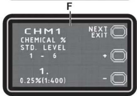

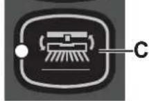
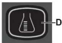
Figure 7
Figure 8
P100870
Figure 9
P100871
Figure 11
P100850
NETTOYAGE DE LA BROSSE À DISQUE

AVERTISSEMENT!
Figure 12
P100873
NETTOYAGE DU FILTRE DE LA SOLUTION
MANUAL PURPOSE AND CONTENTS 2
TARGET 2
HOW TO KEEP THIS MANUAL....2
DECLARATION OF CONFORMITY 2
IDENTIFICATION DATA....2
OTHER REFERENCE MANUALS....2
SPARE PARTS AND MAINTENANCE....2
CHANGES AND IMPROVEMENTS 2
VISIBLE SYMBOLS ON THE MACHINE....3
SYMBOLS THAT APPEAR ON THIS MANUAL....4
GENERAL INSTRUCTIONS....4
MACHINE DESCRIPTION....6
MACHINE STRUCTURE 6
CONTROL PANEL 8
ACCESSORIES/OPTIONS....9
TECHNICAL DATA....9
WIRING DIAGRAM....10
USE/OPERATION 11
MAGNETIC SMART KEY 11
BATTERY CHECK/SETTING ON A NEW MACHINE....11
BATTERY INSTALLATION....11
BEFORE MACHINE START-UP 12
MACHINE START AND STOP 14
MACHINE OPERATION (SCRUBBING/DRYING)....15
TANK EMPTYING....17
AFTER USING THE MACHINE....17
SQUEEGEE CLEANING 22
SQUEEGEE BLADE CHECK AND REPLACEMENT....22
CLEANING THE BRUSH....23
RECOVERY TANK CLEANING 23
SOLUTION FILTER CLEANING 24
DETERGENT TANK CLEANING 24
DRAINING THE ECOFLEX SYSTEM....25
FUSE CHECK/REPLACEMENT....25
SAFETY FUNCTIONS 25
EMERGENCY PUSH-BUTTON....25
ANTI-SKID SAFETY SYSTEM 25
DRIVER'S SEAT MICROSWITCH....25
ELECTROMAGNETIC BRAKE 25
TROUBLESHOOTING 26
SCRAPPING 27
INTRODUCTION

NOTE
The numbers in brackets refer to the components shown in Machine Description chapter.
MANUAL PURPOSE AND CONTENTS
The purpose of this Manual is to provide the operator with all necessary information to use the machine properly, in a safe and autonomous way. It contains information about technical data, safety, operation, storage, maintenance, spare parts and disposal. Before performing any procedure on the machine, the operators and qualified technicians must read this Manual carefully. Contact Nilfisk in case of doubts concerning the interpretation of the instructions and for any further information.
TARGET
This Manual is intended for operators and technicians qualified to perform the machine maintenance.
The operators must not perform procedures reserved for qualified technicians. Nilfisk will not be answerable for damages coming from the non-observance of this prohibition.
HOW TO KEEP THIS MANUAL
The Instructions for Use Manual must be kept near the machine, inside an adequate case, away from liquids and other substances that can cause damage to it.
DECLARATION OF CONFORMITY
The Declaration of Conformity, supplied with the machine, certifies the machine conformity with the law in force.

NOTE
Two copies of the original declaration of conformity are provided together with the machine documentation.
IDENTIFICATION DATA
The machine serial number and model name are marked on the plate (23).
Year of production (Date code: A17 means January 2017) and product code are marked on the same plate.
This information is useful when requiring machine spare parts. Use the following table to write down the machine identification data.
Model
Model Number
Serial Number
OTHER REFERENCE MANUALS
- Electronic battery charger Manual, to be considered as integral part of this Manual
– Spare Parts List (supplied with the machine)
– Service Manual (that can be consulted at Nilfi sk Service Centers)
SPARE PARTS AND MAINTENANCE
All necessary operating, maintenance and repair procedures must be performed by qualified personnel or by Nilfisk Service Centers. Only original spare parts and accessories must be used. Contact Nilfisk for service or to order spare parts and accessories, specifying the model name, model number and serial number.
CHANGES AND IMPROVEMENTS
Nilfisk constantly improves its products and reserves the right to make changes and improvements at its discretion without being obliged to apply such benefits to the machines that were previously sold.
Any change and/or addition of accessory must be approved and performed by Nilfisk.
The SC2000 scrubber-dryer is used to clean (scrubbing and drying) smooth and solid floors, in commercial or industrial environment, under safe operation conditions by a qualified operator.
The scrubber-dryer cannot be used for fitted carpet and carpet cleaning.
CONVENTIONS
Forward, backward, front, rear, left or right are intended with reference to the operator on the driver's seat, in the driving position (12).
UNPACKING/DELIVERY
To unpack the machine, carefully follow the instructions on the packing.
To move the machine manually, see the Pushing/Towing The Machine paragraph.
When the machine is delivered, check that the packing and the machine were not damaged during transportation.
In case of visible damages, keep the packing and have it checked by the carrier that delivered it. Call the carrier immediately to fill in a damage claim.
Please check that the following items have been supplied with the machine:
- Technical documents:
- Scrubber-dryer Instructions for Use Manual
• Electronic battery charger manual (if installed)
• Scrubber-dryer Spare Parts List
- No. 2 lamellar fuses
- No. 1 battery connector (only for machines without on-board battery charger)
- No. 2 shims for 6 V battery compartment (only for machines without on-board batteries)
SAFETY
The following symbols indicate potentially dangerous situations. Always read this information carefully and take all necessary precautions to safeguard people and property.
The operator's cooperation is essential in order to prevent injury. No accident prevention program is effective without the total cooperation of the person responsible for the machine operation. Most of the accidents that may occur in a factory, while working or moving around, are caused by failure to comply with the simplest rules for exercising prudence. A careful and prudent operator is the best guarantee against accidents and is essential for successful completion of any prevention program.
VISIBLE SYMBOLS ON THE MACHINE
WARNING!
Carefully read all the instructions before performing any operation on the machine.

WARNING!
Do not wash the machine with direct or pressurized water jets.
WARNING!
Do not use the machine on slopes with a gradient exceeding the specifications.
SYMBOLS THAT APPEAR ON THIS MANUAL

DANGER!
It indicates a dangerous situation with risk of death for the operator.

WARNING!
It indicates a potential risk of injury for people.

CAUTION!
It indicates a caution or a remark related to important or useful functions.
Pay careful attention to the paragraphs marked by this symbol.

NOTE
It indicates a remark related to important or useful functions.

CONSULTATION
It indicates the necessity to refer to the Instructions for Use Manual before performing any procedure.
GENERAL INSTRUCTIONS
Specific warnings and cautions to inform about potential damages to people and machine are shown below.

DANGER!
- Before performing any maintenance, repair, cleaning or replacement procedure, remove the magnetic smart key (or ignition key) and disconnect the battery connector.
- This machine must be used by properly trained operators only.
- Do not wear jewels when working near electrical components.
- Do not work under the lifted machine without supporting it with safety stands.
- Do not operate the machine near toxic, dangerous, flammable and/or explosive powders, liquids or vapours. This machine is not suitable for collecting dangerous powders.
- When using lead (WET) batteries, keep sparks, flames and smoking materials away from the batteries. During the normal operation explosive gases are released.
- When using lead (WET) batteries, battery charging produces highly explosive hydrogen gas. During battery charging, lift the recovery tank and perform this procedure in well-ventilated areas and away from naked flames.

WARNING!
- Carefully read all the instructions before performing any maintenance/repair procedure.
- The magnetic smart key has a built-in magnet. Do not place objects having magnetic bands (such as credit cards, electronic keys, phone cards) near the key. The built-in magnet can damage or erase the data stored on the magnetic bands.
Before using the battery charger, ensure that frequency and voltage values, indicated on the machine serial number plate, match the electrical mains voltage. - Do not pull or carry the machine by the battery charger cable and never use the battery charger cable as a handle. Do not close a door on the battery charger cable, or pull the battery charger cable around sharp edges or corners. Do not run the machine on the battery charger cable.
- Keep the battery charger cable away from heated surfaces.
- Do not charge the batteries if the battery charger cable or the plug are damaged.
- To reduce the risk of fire, electric shock, or injury, do not leave the machine unattended when it is plugged in. Before performing any maintenance procedure, disconnect the battery charger cable from the electrical mains.
- Do not smoke while charging the batteries.
- To avoid any unauthorized use of the machine, remove the magnetic smart key (or ignition key).
- Do not leave the machine unattended without being sure that it cannot move independently.

WARNING!
- Always protect the machine against the sun, rain and bad weather, both under operation and inactivity condition. This machine must be used in dry conditions, it must not be used or kept outdoors in wet conditions.
- Before using the machine, close all doors and/or covers as shown in the Instructions for Use Manual.
- This machine is not intended for use by persons (including children) with reduced physical, sensory or mental capabilities, or lack of experience and knowledge, unless they have been given supervision or instruction concerning use of the machine by a person responsible for they safety.
Children should be supervised to ensure that they do not play with the machine.
- Close attention is necessary when used near children.
- Use only as shown in this Manual. Use only Nilfisk's recommended accessories.
- Check the machine carefully before each use, always check that all the components have been properly assembled before use. If the machine is not perfectly assembled it can cause damages to people and properties.
- Take all necessary precautions to prevent hair, jewels and loose clothes from being caught by the machine moving parts.
- Do not use for cleaning purposes on surfaces having a gradient exceeding that marked on the machine.
- Do not tilt the machine more than the angle marked on the machine, in order to prevent instability.
- Do not use the machine in particularly dusty areas.
- Use the machine only where a proper lighting is provided.
- If the machine is to be used where there are other people besides the operator, it is necessary to install the beacon light (optional).
- While using this machine, take care not to cause damage to people or objects.
- Do not bump into shelves or scaffoldings, especially where there is a risk of falling objects.
- Do not lean liquid containers on the machine, use the relevant can holder.
- The machine working temperature must be between 0^ and +40^ .
- The machine storage temperature must be between 0^ and +40^ .
- The humidity must be between 30% and 95% .
- When using floor cleaning detergents, follow the instructions on the labels of the detergent bottles.
- To handle floor cleaning detergents, wear suitable gloves and protections.
- Do not use the machine as a means of transport.
- Do not allow the brush/pad to operate while the machine is stationary to avoid damaging the floor.
- In case of fire, use a powder fire extinguisher, not a water one.
- Do not tamper with the machine safety guards and follow the ordinary maintenance instructions scrupulously.
- Do not allow any object to enter into the openings. Do not use the machine if the openings are clogged. Always keep the openings free from dust, hairs and any other foreign material which could reduce the air flow.
- Do not remove or modify the plates affixed to the machine.
- To manually move the machine, the electromagnetic brake must be disengaged. After moving the machine manually, engage the electromagnetic brake again. Do not use the machine when the electromagnetic brake handwheel is screwed down.
- When the machine is to be pushed for service reasons (missing or discharged batteries, etc.), the speed must not exceed 4 km/h.
- This machine cannot be used on roads or public streets.
- Pay attention during machine transportation when temperature is below freezing point. The water in the recovery tank or in the hoses could freeze and seriously damage the machine.
- Use brushes and pads supplied with the machine or those specified in the Instructions for Use Manual. Using other brushes or pads could reduce safety.
- In case of machine malfunctions, ensure that these are not due to lack of maintenance. If necessary, request assistance from the authorised personnel or from an authorised Service Center.
- If parts must be replaced, require ORIGINAL spare parts from an Authorised Dealer or Retailer.
- To ensure machine proper and safe operation, the scheduled maintenance shown in the relevant chapter of this Manual, must be performed by the authorised personnel or by an authorised Service Center.
- Do not wash the machine with direct or pressurised water jets, or with corrosive substances.
- The machine must be disposed of properly, because of the presence of toxic-harmful materials (batteries, etc.), which are subject to standards that require disposal in special centres (see Scrapping chapter).
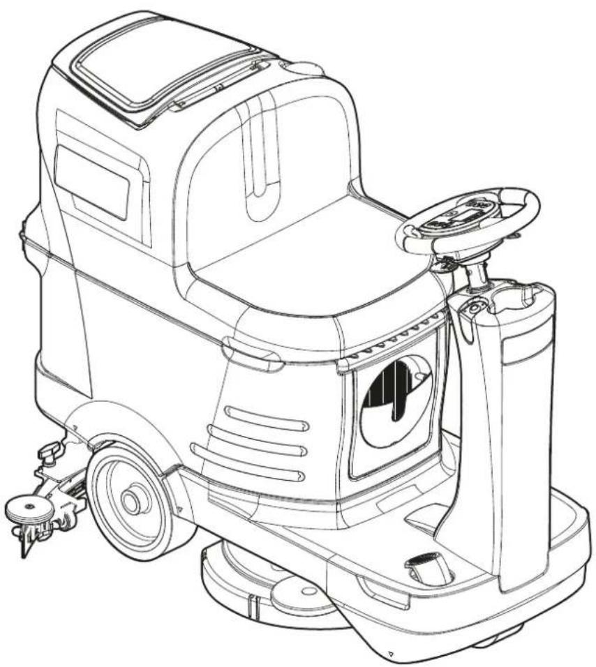
MACHINE DESCRIPTION
MACHINE STRUCTURE
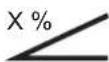
- Steering wheel with control panel (see the following paragraph)
- Drive pedal
- Front steering wheel
- Electromagnetic brake locking/unlocking lever
- EMERGENCY push-button, to stop immediately all functions
- Battery connector
- Brush deck
- Solution fi Iter
- Solution valve
A) Open valve
B) Closed valve
- Solenoid valve
- Squeegee hook
- Seat
- Squeegee
- Squeegee bumper wheels
- Solution tank
- Solution drain and level check hose
- Dumping recovery tank assembly
- Recovery tank cover
- Can holder
- Battery charger cable housing and document holder
- Battery charger cable (*)
(*) Optional for BASIC version
P100859
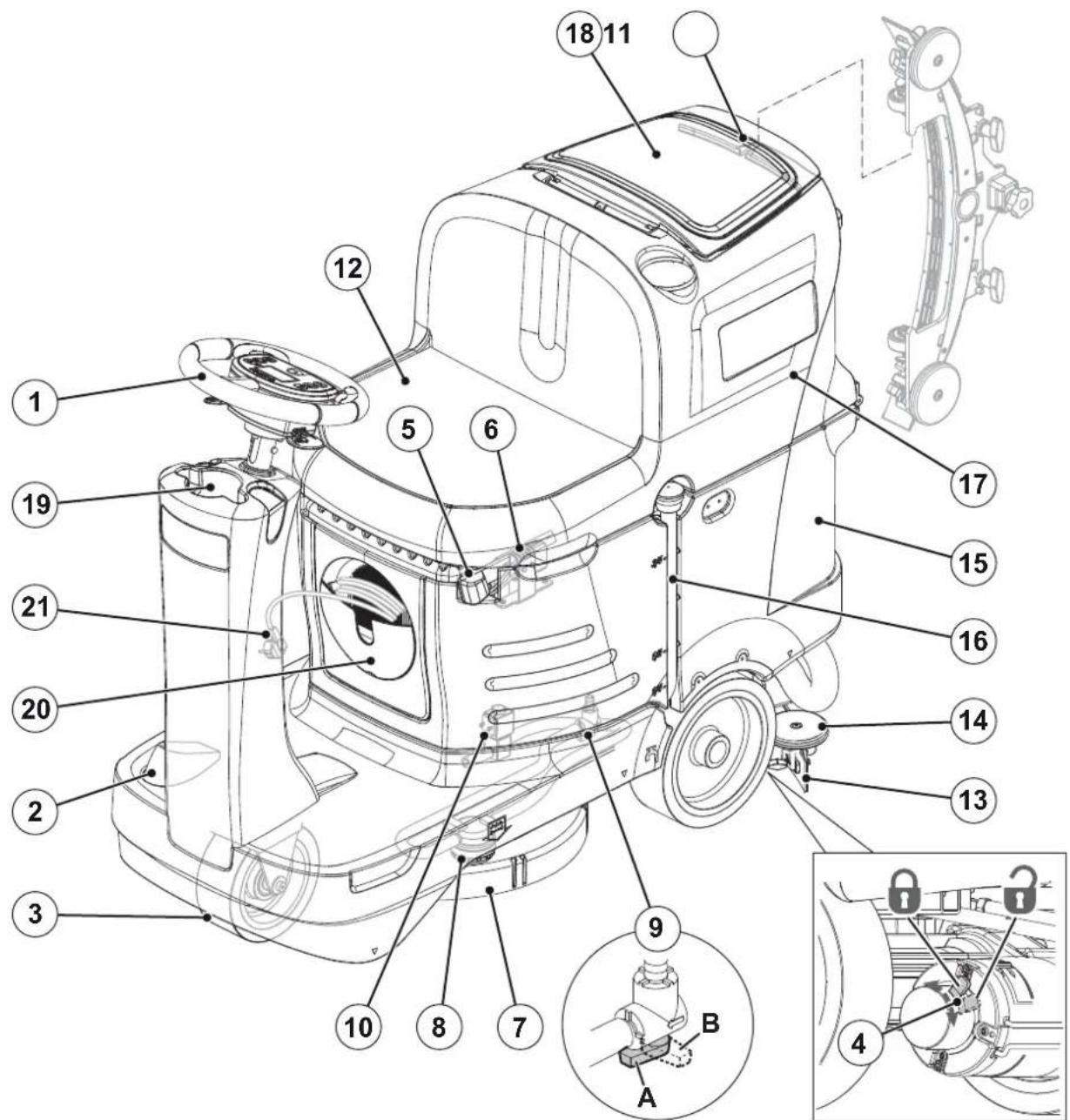
MACHINE STRUCTURE (Continues)
- Battery charger (*)
- Serial number plate/technical data/conformity certification
- Rear driving wheels
- Solution tank filler neck
- Recovery water drain hose
- Container with debris collection grid
- Vacuum grid with automatic shut-off fl oat
- Recovery water tank cover (open)
- Squeegee vacuum hose
-
Squeegee support wheel
-
Squeegee mounting handwheels
- Squeegee adjusting knob
- Brush deck bumper wheel
- Tank assembly and seat lifting handle
- Tank assembly and seat support rod
- Batteries (*)
- EcoFlex detergent canister (*)
- Electronic component compartment cover
- Lifted recovery tank assembly and driver's seat
(*) Optional for BASIC version
P100860
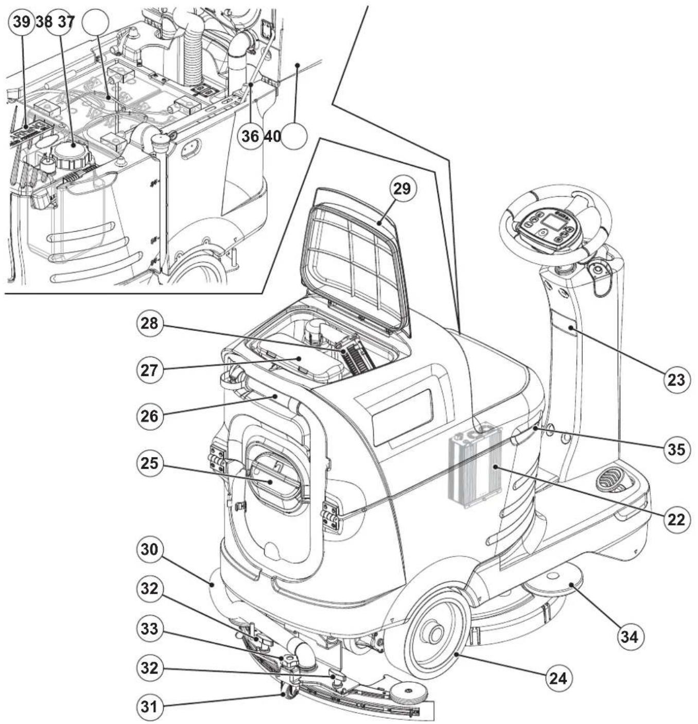
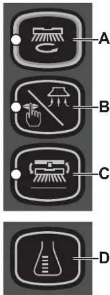
CONTROL PANEL
- Smart key reader
- Start/stop switch
-
One-Touch™ Scrub ON/OFF push-button
-
Flashing green LED: Brush deck moving up/down
• Steady green LED: Ready for work -
Steady red LED: - Extra pressure active (hold for one second)
-
Vacuum system adjustment/deactivation push-button:
• LED on - vacuum system activated
- Brush engage/disengage push-button:
- Flashing LED - system activated
- Detergent percentage adjustment push-button (*)
- Detergent flow adjustment button
- Horn switch
- Reverse gear activation/deactivation lever
-
EcoFlex activation/deactivation lever (*)
-
Display:
A) Hours worked
B) Battery type
C) Battery charge level
D) Vacuum mode (standard / silent)
E) Brush work mode
F) Detergent solution flow quantity
G) Detergent quantity (*)
H) Percentages of detergent in the washing water (*)
I) EcoFlex system override timer (*)
J) Anti-skid control
K) Maximum machine speed setting
L) Auto shut-off timer
M) Battery charging with on-board battery charger (*)
N) EcoFlex system drain activation (*)
-
Magnetic smart key
-
Blue = User key
• Yellow = Supervisor key
(*) Optional for BASIC version
P100861
ACCESSORIES/OPTIONS
In addition to the standard components, the machine can be equipped with the following accessories/options, according to the machine specific use:
- GEL/AGM batteries
-EcoFlex
– Electronic battery charger - Pivoting light
- Brushes of different materials
- Broom holder
– Pads of different materials - Waste basket
- Splash guard
- Enhanced vacuum system motor
– Squeegee blades of different materials - USB port
- Filling hose
For further information concerning the optional accessories, contact an authorised Retailer.
TECHNICAL DATA
| Model SC2000 53 B SC2000 53 B FULL PKG | ||
| Solution tank capacity 70 litres | ||
| Recovery tank capacity 70 litres | ||
| Machine length 1,270 mm | ||
| Machine width with squeegee 720 mm | ||
| Machine width without squeegee 550 mm | ||
| Machine height 1,020 mm | ||
| Turning space for U-turns 1,800 mm | ||
| Cleaning width 530 mm | ||
| Rear driving wheel diameter | 254 mm | |
| Rear driving wheel specific pressure on the floor | 1.0 N/mm^2 | |
| Front steering wheel diameter | 200 mm | |
| Front wheel specific pressure on the floor | 1.3 N/mm^2 | |
| Brush/pad diameter 530/508 mm | ||
| Brush pressure with extra pressure function turned off | 15 kg | |
| Brush pressure with extra pressure function turned on | 30 kg | |
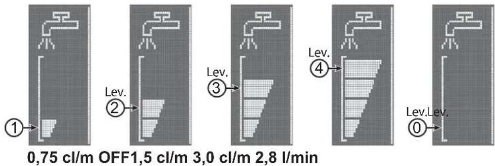
| Solution flow values | 0.75 cl/m / 1.5 cl/m / 3.0 cl/m / (2.8 l/min, if enabled) | |
| EcoFlex system detergent percentage | - | 0.25 % - 3 % |
| Sound pressure level at workstation (ISO 11201, ISO 4871, EN 60335-2-72) (LpA) | 68 ± 3 dB(A) | |
| Sound pressure level at workstation in silent mode (LpA) | 62 ± 3 dB(A) | |
| Machine sound power level (ISO 3744, ISO 4871, EN 60335-2-72) (LwA) | 84 dB(A) | |
| Vibration level at the operator's arms (ISO 5349-1, EN 60335-2-72) | 3.3 m/s^2 | |
| Vibration level at the operator's body (ISO 5349-1, EN 60335-2-72) | 0.9 m/s^2 | |
| Maximum cleaning gradeability | 15 % | |
| Maximum transport gradeability | 18 % | |
| Drive system motor power | 400 W | |
| Drive speed (variable) | 0 - 6 km/h | |
| Vacuum system motor power | 310 W | |
| Vacuum system circuit capacity | 1,000 mm H_2O | |
| Brush motor power | 450 W | |
| Brush rotation speed | 155 rpm | |
| Total absorbed power (*) | 620 W | |
| IP protection class | X4 | |
| Protection class (electric) | III (I for the battery charger) | |
| Battery compartment size | 350x360x280 mm | |
| System voltage | 24V | |
| Standard batteries (2) | - | Discover 12V-105Ah |
| Battery charger | - | 100-240Vac 50-60Hz, 24Vdc 13A |
| Operating time (standard batteries) (*) | 2.5 hour | |
| Weight without batteries and with empty tanks | 119 kg | 121 kg |
| Gross vehicle weight (GVW) | 342 kg | |
| Shipping weight | 152 kg | 228 kg |
(*) Values reflect standard operating conditions (EN 60335-2-72)
Maximum permissible weight of the operator
120 kg
WIRING DIAGRAM
Key
BAT 24 V batteries
BE Pivoting light (optional)
BRK Electromagnetic brake
C1 Battery connector
C2 Battery charger connector (optional)
CH Battery charger (optional)
EB1 Function electronic board
EB2 Display electronic board
EB3 Dashboard instrument board
EV1 Solenoid valve
F1 Function electronic board fuse
F2 Signal circuit fuse
F3 Brush motor fuse
F4 Drive system motor fuse
IB Smart key
M1 Brush motor
M2 Vacuum system motor
M3 Drive system motor
M4 EcoFlex pump (optional)
M5 Brush deck actuator motor
M6 Squeegee actuator motor
POT Drive pedal potentiometer
S1 Solution level sensor
SW3 Seat microswitch
SW4 Anti-skid control sensor
TCU TrackClean (optional)
USB USB port (optional)
Colour codes
BK Black
BU Blue
BN Brown
GN Green
GY Grey
OG Orange
PK Pink
RD Red
VT Violet
WH | White
YE | Yellow
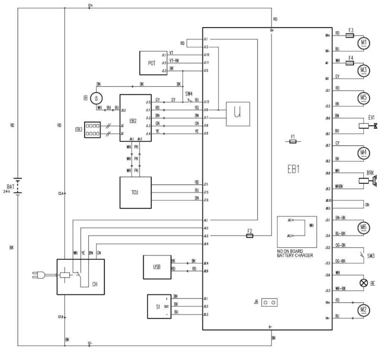
P100862
USE/OPERATION

WARNING!
On some points of the machine there are some adhesive plates indicating:
DANGER
- WARNING
- CAUTION
- CONSULTATION
While reading this Manual, the operator must pay particular attention to the symbols shown on the plates (see Visible Symbols On The Machine paragraph).
Do not cover these plates for any reason and immediately replace them if damaged.
MAGNETIC SMART KEY
A magnetic smart key (52) is required to start the machine. If the start switch (42) is pressed and the key is not in the key reader (41), the display will turn on temporarily and it will show a key insertion request, then it will turn off.
There are two different magnetic smart keys:
- "User" key (blue) for scrubbing/drying operations and basic information.
- "Supervisor" key (yellow) for accessing additional features (see the Supervisor key paragraph in Maintenance chapter).
BATTERY CHECK/SETTING ON A NEW MACHINE

WARNING!
The electric components of the machine can be seriously damaged if the batteries are either improperly installed or connected.
The batteries must be installed by qualified personnel only.
Check the batteries for damage before installation.
Handle the batteries with great care.
The machine requires 2 12 V batteries, connected according to the diagram shown in Figure 1.
The machine can be supplied in one of the following modes:
Batteries already installed on the machine
- Ensure that the battery connector (6) is connected.
- When first using the machine with new batteries, perform a full charging cycle (see the procedure in Maintenance chapter).
Without batteries
- Buy appropriate batteries (see "Technical Data" paragraph). For battery choice and installation, apply to qualified battery Retailers.
- Set the machine according to the type of batteries installed as shown in the Super User key section of the Maintenance chapter.
BATTERY INSTALLATION
Battery Installation
- Remove the user key (52).
- Disconnect the battery connector by pressing the emergency push-button (5).
- Lift the cover (18) and check that the recovery tank (17) is empty, otherwise empty it with the drain hose (26).
- Close the cover (18).
- Grasp the handle (35) and carefully lift the recovery tank assembly (17).
- The machine is supplied with cables suitable to install 2 12 V batteries.
- Carefully lift the batteries until the relevant compartment, then place them properly.
- Route and install the battery cable as shown in Figure 1, then carefully tighten the nut on each battery terminal.
- Place the protection cap on each terminal, then connect the battery connector (6).
- Disengage the support rod (36), then grasp the handle (35) and carefully lower the recovery tank assembly (17).
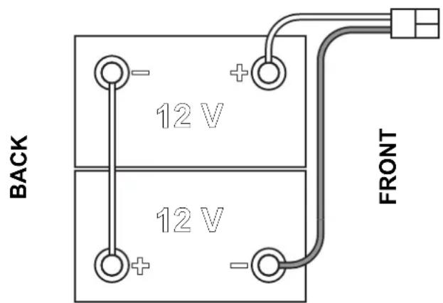
Figure 1
P100863
Battery Charging
- Fully charge the batteries (see the procedure in Maintenance chapter).
BEFORE MACHINE START-UP

WARNING!
When starting the machine, or before operating the One Touch button (43), make sure that there is no foreign material between the deck and the tank assembly which could obstruct the deck movement. If the machine has been turned off without lifting the deck, the deck would lift automatically at next machine start-up.
Brush or pad-holder removal/installation
According to the kind of cleaning to be performed, the machine can be equipped either with the brush (A, Fig. 2) or the pad-holder (B) with pad (C) together with the appropriate deck.
- Place the brush (A) or the pad-holder (B) under the deck (7).
- Place the user key (52) in the key reader (41), then press the push-button (42) to start the machine.
- Press the One-Touch button (43) to lower the deck onto the brush.
- Press the switch (45) to engage the brush.
- To remove the brush, the deck must be lifted by pressing the One-Touch push-button (43), then press the release push-button (45). When the display shows the icon (51-K), wait for the brush to fall on the floor.
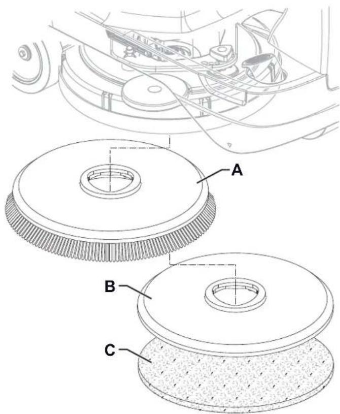
Figure 2
P100864
Available brushes and their relevant application guides (suggestions only)
| Models 46 GRIT 80 GRIT 180 GRIT 240 GRIT 500 | GRIT PROLE | NE PROLITE | UNION MIX | ||||
| General cleaning: | |||||||
| Concrete | |||||||
| Terrazzo floor | |||||||
| Ceramic tiles/quarrystones | |||||||
| Marble | |||||||
| Vinyl tiles | |||||||
| Rubber tiles | |||||||
| Polishing: | |||||||
| Rubber tiles | |||||||
| Marble | |||||||
| Vinyl tiles | |||||||
Squeegee installation
- Install the squeegee (A, Fig. 3) and fasten it to the bracket (C) with the handwheels (B).
- If necessary, adjust the squeegee with the knob (D) so that the rear blade (E) and front blade (F) touch the floor as shown in the figure.
Solution tank fi lling

CAUTION!
Use only low-foam and non-fl ammable detergents, intended for automatic scrubber applications.

WARNING!
When using floor cleaning detergents, follow the instructions on the labels of the detergent bottles.
To handle floor cleaning detergents, wear suitable gloves and protections.

NOTE
If the machine is equipped with EcoFlex system (optional) pour clean water in the tank, otherwise pour solution.
- Ensure that the solution valve (9) is open (9-A).
- To fill the solution tank (15) remove the plug (25) to reach the filler neck.
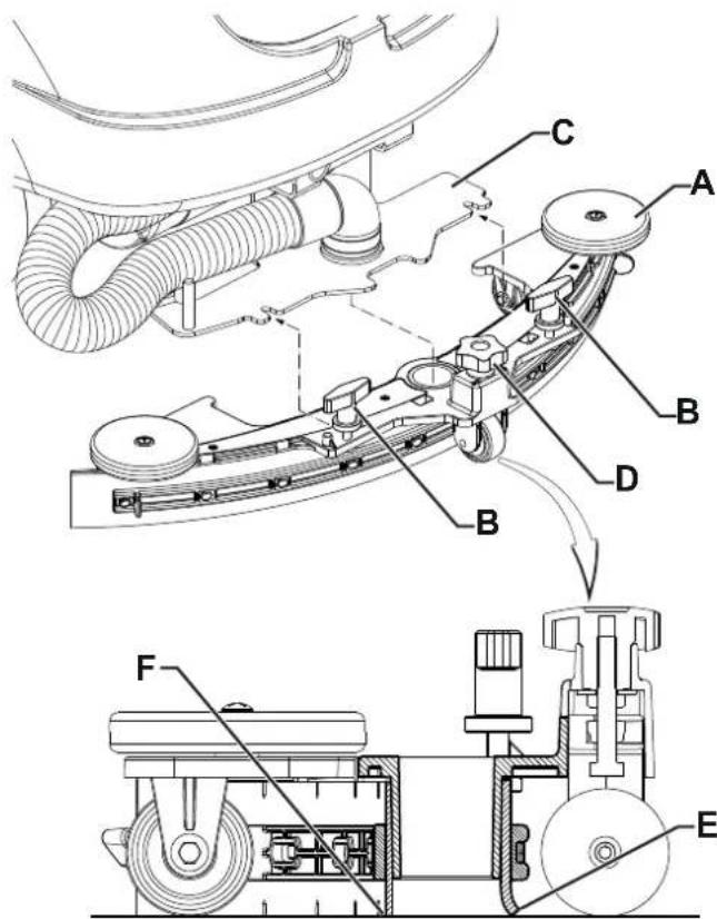
Figure 3
P100865
(For machines without EcoFlex system)
- Fill the tank (15) with a solution suitable for the work to be performed.
Do not fill the tank completely, leave a few inches from the edge. Use the level hose (16) as reference. Always follow the dilution instructions on the label of the chemical product used to prepare the solution. The solution temperature must not exceed 40 °C.
(For machines with EcoFlex system)
- Fill the tank (15) with clean water. If equipped, use the water filler hose (optional) located in the filler neck (25). Do not fill the tank completely, leave a few inches from the edge. Use the level hose (16) as reference. The water temperature must not exceed 40^ C.
Detergent tank fi lling (For machines with EcoFlex system)
- Lift the cover (18) and check that the recovery tank (17) is empty, otherwise empty it with the drain hose (26).
- Close the cover (18).
- Grasp the handle (35) and carefully lift the recovery tank assembly (17).
- Fill the tank (38) with a detergent suitable for the work to be performed (highly concentrated detergent). Do not fill the detergent tank completely, leave a few inches from the edge.

NOTE
In case of new system, system emptied for cleaning, etc., wait for the hoses to fill up completely before turning on. In order to fill the EcoFlex system quickly it may be useful to drain it once or several times (see the procedure in Maintenance chapter).
MACHINE START AND STOP
Starting the machine
- Prepare the machine as shown in the previous paragraph.
- Place the user key (52) in the key reader (41), then press the push-button (42) to start the machine.
- In the first 2 seconds after machine start-up, the display (51) indicates the machine working hours (51-A) and the type of batteries installed (51-B).

NOTE
Check the battery charge level.
When the display shows at least one segment of the battery symbol (51-C) which is on but not flashing, the machine is ready for use.
When the battery symbol (51-C) shows just one segment flashing, the batteries have to be charged (see the procedure in Maintenance chapter).
- Drive the machine to the working place, by starting it with both hands on the steering wheel (1) and by pressing the drive pedal (2).
The drive speed can be adjusted from zero to maximum speed according to the pressure on the drive pedal (2).
- The forward/reverse gear is selected with the relevant lever (49) which is at the right of the steering wheel.

NOTE
The driver's seat (12) is equipped with a safety sensor, which allows the machine to be driven by pressing the pedal (2) only when the operator is on the driver's seat.

NOTE
The machine is equipped with an anti-skid safety system (display icon (51-J)) that reduces the speed when turning and when the machine tilts laterally, irrespectively of the pressure on the pedal.
In this case, the reduction of speed is not a malfunction but a characteristic that improves the machine stability and safety in every condition.

CAUTION!
In case of use of the machine on slopes, drive very careful and reduce the speed mostly when the floor is wet or slippery.
Always take the ramp perpendicularly to the slope.
To park the machine on slope, reach the parking position and turn off the machine.
Never exceed the gradients indicated on the "Technical Data" paragraph.
Stopping the machine
- Stop the machine by releasing the drive paddle (2). It is not necessary to lock the machine during stopping or parking, because the electromagnetic brake on the wheels turn on automatically when the drive pedal is not pressed.
- Turn off the machine by pressing the push-button (42) and remove the user key (52).

NOTE
The machine is running without the user key (52) in the key reader (41), it automatically switches off after 10 seconds of complete idle.

NOTE
If the machine is on but not working, it automatically turns off after 5 minutes.

CAUTION!
In the event of an emergency, to stop all machine functions immediately, firmly press the push-button (5).
To reset the machine operation, lift the recovery tank assembly (17) and reconnect the battery connector (6).
MACHINE OPERATION (SCRUBBING/DRYING)
- Start the machine as shown in the previous paragraph.
- Press the One Touch button (43) to lower the brush deck (7) and the squeegee (13) and start scrubbing and drying.
- Start scrubbing, by starting it with both hands on the steering wheel (1) and by pressing the drive pedal (2) as necessary.

NOTE
The machine is equipped with a safety system that turns on the brush and vacuum system only when the machine is moving.
- Adjust the detergent flow by pressing the push-button (47) as necessary, depending on the type of cleaning to be performed.

NOTE
For the first 3 flow levels (Fig. 4), the amount of solution dispensed is automatically adjusted according to the machine speed, in order to obtain a constant amount of solution per linear meter of cleaning. Level 4 (when enabled) supplies the maximum possible quantity of detergent solution, regardless of the machine speed (to enable or disable this feature, see the Supervisor key paragraph in Maintenance chapter).
The level 0 closes the solution flow completely.
flowchart
graph LR
    A["Step ①: 0.75 cl/m OFF1.5 cl/m 3.0 cl/m 2.8 l/min"] --> B["Step ②: Lev."]
    B --> C["Step ③: Lev."]
    C --> D["Step ④: Lev."]
    D --> E["Step ⑤: Lev.Lev."]
Figure 4
P100866
- If necessary, deactivate the vacuum system by pressing the push-button (44, LED off), then press it again to reactivate it (LED on). To reduce the noise, turn on the vacuum system mute function by pressing the push-button (44) (display icon 51-D).

NOTE
For correct scrubbing/drying of floors at the sides of the walls, Nilfisk suggests to go near the walls with the right side of the machine as shown in figure 5.
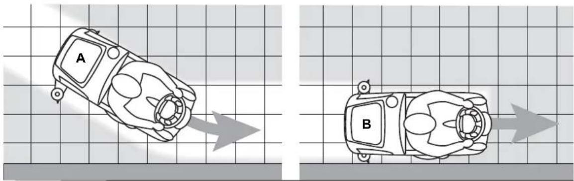
natural_image
Two overhead views of a car on grid paper, labeled A and B, with no visible text or symbols.Figure 5
P100867
- To stop scrubbing/drying, press the One-Touch push-button (43) and wait for the brush deck (7) to lift. After 10 seconds, the vacuum system turns off too and the squeegee (13) lifts.
Adjusting of detergent concentration in the washing water
(For machines with EcoFlex system)
The system for mixing the detergent in the washing water is automatically activated when the brush is running.
The percentage of detergent added to the washing water is set to level 1 (Fig. 6).
By pressing the push-button (46), it is possible to set the percentage level to 2, or reset it to level 0.
The set percentages are shown on the display (51-G).
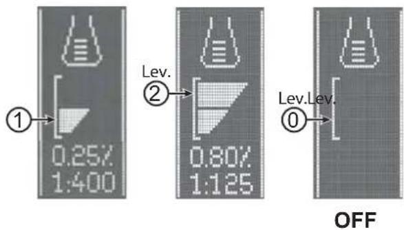
Figure 6
P100868
EcoFlex System
Use the EcoFlex lever (50) when a temporary stronger washing power is needed.
With the EcoFlex system activated, increased solution flow, activation of the extra pressure of the brush and an increase in the solution detergent concentration (level 2 if the level was set to 1 - level 1 if the level was set to 0) is obtained.
By using the EcoFlex lever (50) again, the original settings are restored.

NOTE
If the lever (D) is not used once again, the original settings are restored automatically after 60 seconds.

NOTE
All of the above solution flow and detergent concentration values are factory settings.
To change these settings, see the Supervisor key paragraph in Maintenance chapter.
Working with brush extra pressure function turned on
If the floor proves to be particularly difficult to clean, it is possible to turn on the brush extra pressure function, according to the following procedure:
- Press the One-Touch push-button (43) to lower the brush deck as shown in "Starting The Machine" paragraph.
- Press and hold the One-Touch push-button (43) for more than 1 second. The extra pressure function activation is shown by
LED which turns from green to red, and by the icon on the display (51).
- To return to normal pressure, press and hold the One-Touch push-button (43) for more than 1 second.
- To lift the brush deck without returning to the normal pressure, press the One-Touch push-button (43) and release it immediately.

CAUTION!
In case of brush motor overload, due to foreign bodies which prevent them from turning, or to excessively aggressive floors/brushes, the safety system stops the brush after about one minute of continuous overload. If the overload takes place when the extra pressure function is on, the system automatically turns the extra pressure function off.
If the overload persists, the brush stops.
To start scrubbing again after a brush stop due to overload, turn off and then on the machine with the push-button (42).
Battery discharge during operation
When there is only one segment turned on and flashing on the battery symbol (51-C), it is advisable to charge the batteries, because the residual autonomy will last for a few minutes (depending on battery characteristics and work to be performed). When the battery symbol (51-C) is flashing and no segment is turned on, the battery autonomy is over. After a few seconds, the brush is automatically tuned off, while the vacuum system and the drive system stay on, to finish drying the floor and drive the machine to the appointed recharging area.

CAUTION!
Do not use the machine with discharged batteries, to avoid damaging the batteries and reducing the battery life.

NOTE
In case the machine drive system cannot be used in order to move the machine, see Pushing/Towing The Machine paragraph.
TANK EMPTYING
An automatic float shut-off system (28) turns off the vacuum system when the recovery tank (17) is full.
The vacuum system deactivation is signalled by a sudden increase in the vacuum system motor noise, and the floor is not dried.

CAUTION!
If the vacuum system turns off accidentally (for example, when the float is activated because of a sudden machine movement), to resume the operation: turn off the vacuum system by pressing the push-button (44), then open the cover (18) and check that the float inside the grid (28) has gone down. Then close the cover (18) and turn on the vacuum system by pressing the push-button (44).
When the recovery tank (17) is full, empty it according to the following procedure.
Recovery tank emptying
- Lift the brush deck and the squeegee by pressing the One-Touch push-button (43).
- Drive the machine to the appointed disposal area.
- Turn off the machine with the push-button (42) and remove the user key (52).
- Empty the recovery tank (17) with the drain hose (26). Then, rinse the tank with clean water.
Solution tank emptying
- Perform steps 1 to 3.
- Empty the detergent solution tank (15) using the level hose (16). Then, rinse the tank with clean water.
AFTER USING THE MACHINE
After working, before leaving the machine:
- Remove the brush as shown in the relevant paragraph.
- Remove the user key (52).
- Empty the tanks (17 and 15) as shown in the previous paragraph.
- Remove the squeegee (13) and clean it with hot water. Open the recovery tank cover (18) and hang the squeegee on the tank hook (11).
- Perform the daily maintenance procedures (see the Maintenance chapter).
- Store the machine in a clean and dry place, with the brush and the squeegee lifted or removed.
To push/tow the machine easily when the drive system cannot be used (for example in case of missing batteries, discharged batteries, etc.), disengage the electromagnetic brake with the lever (4).
When pushing/towing procedure is over, turn the lever (4) to the original position, to engage the electromagnetic brake again.

WARNING!
If the lever (4) is not repositioned after pushing/towing the machine, the electromagnetic brake is disengaged.

WARNING!
Do not start the machine when the electromagnetic brake is disengaged.
For safety reasons, it is recommended to disengage the electromagnetic brake only for the time necessary to manually move the machine.
MACHINE LONG INACTIVITY
If the machine is not going to be used for more than 30 days, proceed as follows:
- Perform the procedures shown in After using the machine paragraph.
- For versions with EcoFlex system, empty the detergent tank (38) and clean the system with a draining cycle (see the procedure in Maintenance chapter).
- Close the solution tank valve (9-B).
- Press the emergency push-button (5) to disconnect the battery connector (6).
MAINTENANCE
The lifespan of the machine and its maximum operating safety are ensured by correct and regular maintenance.
The following table provides the scheduled maintenance. The intervals shown may vary according to particular working conditions, which are to be defined by the person in charge of the maintenance.

WARNING!
The procedures must be performed with the machine off and the battery disconnected.
Moreover, read carefully the instructions in the Safety chapter before performing any maintenance procedure.
All scheduled or extraordinary maintenance procedures must be performed by qualified personnel, or by an authorised Service Center.

CAUTION!
When the Service icon scheduled maintenance

appears on the display (51), contact an authorised Nilfisk Service Centre for
This Manual describes only the simplest and most common maintenance procedures.
For other maintenance procedures shown in the Scheduled Maintenance Table, refer to the Service Manual that can be consulted at any Service Center.
SCHEDULED MAINTENANCE TABLE
| Procedure | Daily, after using the machine | Weekly | Every six months | Yearly |
| Battery Charging | ||||
| Squeegee Cleaning | ||||
| Brush/pad cleaning | ||||
| Recovery tank and debris tray cleaning, and cover gasket check | ||||
| EcoFlex system (optional) cleaning and draining | ||||
| Squeegee blade check | ||||
| Solution Filter Cleaning | ||||
| Battery (WET) fluid level check | ||||
| Squeegee blade replacement | ||||
| Electromagnetic brake efficiency check | (1) | |||
| Drive and brush motor vent check and cleaning (1) | ||||
| Brush motor carbon brush check or replacement (1) | ||||
| Drive system motor carbon brush check or replacement (1) |
(1) This maintenance procedure must be performed by an authorised Nilfisk Service Center.
BATTERY CHARGING

NOTE
Charge the batteries when there is only one flashing segment displayed in the battery symbol (51-C), or at the end of the shift.
Keeping the batteries charged make their life last longer.

CAUTION!
When the batteries are discharged, charge them as soon as possible, as that condition makes their life shorter.
Check for battery charge at least once a week.

CAUTION!
If the machine is not equipped with on-board battery charger, choose an external battery charger suitable for the type of batteries installed.

WARNING!
When using lead (WET) batteries, battery charging produces highly explosive hydrogen gas. Charge the batteries in well-ventilated areas and away from naked fl ames.
Do not smoke while charging the batteries.
Keep the recovery tank lifted until the battery charging cycle is over.

WARNING!
Pay careful attention when charging lead batteries (WET) as there may be battery fluid leakages. The battery fluid is corrosive. If it comes in contact with skin or eyes, rinse thoroughly with water and consult a physician.
- Drive the machine to the appointed recharging area.
- Ensure that the machine is off and the user key (52) has been removed.
- Lift the cover (29) and check that the recovery tank (17) is empty; if not, empty it using the drain hose (26).
- Close the cover (18).
- Grasp the handle (35) and carefully lift the recovery tank assembly (17).
- (For WET CELL batteries only) Check the level of electrolyte inside the batteries. If necessary, unscrew the caps and top up. When the correct level is restored, close the caps and clean the tops of the batteries.
Charging the Batteries with an External Battery Charger
- Check that the external battery charger is suitable by referring to the relevant Manual. The battery charger voltage rating must be 24 V.
- Disconnect the battery connector (6) and connect it to the external battery charger.
- Connect the battery charger to the electrical mains.
- After charging, disconnect the battery charger from the electrical mains and from the battery connector (6).
- Connect the battery connector (9) to the machine.
- Disengage the support rod (36), then grasp the handle (35) and carefully lower the recovery tank assembly (17).

WARNING!
Never connect the external battery charger to the opposing part of the connector fixed to the machine. The electronic system could be irreparably damaged.
Battery charging with battery charger installed on the machine
- Plug the battery charger cable (21) into the electrical mains (the mains voltage and frequency must be compatible with the battery charger values shown on the machine serial number plate).

NOTE
When the battery charger is connected to the electrical mains, all machine functions are automatically cut off.
When the first or second segment from the left in the battery symbol (51-M) is flashing, this means that the battery charger is charging the batteries.
When the third segment from the left in the battery symbol (51-M) is flashing, this means that the battery charger is finishing the battery charging cycle.
- When all segments of the battery symbol (51-M) are steadily lit, the battery charging cycle is complete.
- Disconnect the battery charger cable plug (21) from the mains and place it in its holder (20).
- Disengage the support rod (36), then grasp the handle (35) and carefully lower the recovery tank assembly (17).
- Now the machine is ready to be used.

NOTE
For further information about the operation of the battery charger (22), see the relevant Manual.
SUPERVISOR KEY (yellow)
The supervisor key (yellow) allows to check some additional information on some machine operating parameters and to adjust some settings according to specific requirements.
Main Screen (E, Fig. 7)
- Put the supervisor key (yellow) in the key reader (41) instead of the user key (blue), then press the push-button (42) to open the main screen on the display.
- Press push-button (A) to change the machine settings (see Machine Settings Screen section).
- Press push-button (B) to check for any stored machine alarms (see Alarms Log Screen section).
- Press push-button (C) to check the machine's hours of operation (see Operating Time Counter Screen section).
- Press the push-button (D) to enter the user key management menu (see the User Key Management Screen paragraph).
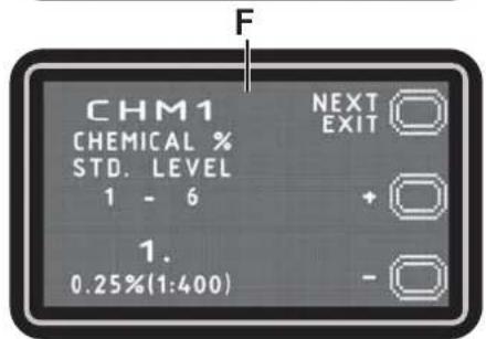
Machine Settings Screen (F, Fig. 7)
This function allows you to customise some parameters described in the following table of modifi able parameters.
- Press push-button (B) to increase the value of the current parameter.
Press push-button (C) to decrease the value of the current parameter. - Press push-button (A) to move to the next parameter.
- To return to the main screen, press and hold the push-button (A) for more than 1 second.
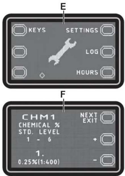
Figure 7
P100869
| TABLE OF MODIFIABLE PARAMETERS Values | ||||
| Code Description Minimum Factory Setting Maximum | ||||
| CHM1 | Detergent concentration level 1 | 0.25 % (1:400) | 0.25 % (1:400) | 3 % (1:33) |
| CHM2 | Detergent concentration level 2 | 0.25 % (1:400) | 0.80 % (1:125) | 3 % (1:33) |
| P1/P3 | Level 1 solution flow rate in relation to level 3(fl ow rate as function of speed) | 0 % | 25 % | 100 % |
| P2/P3 | Level 2 solution flow rate in relation to level 3(fl ow rate as function of speed) | 0 % | 50 % | 100 % |
| P3 | Level 3 solution flow rate (flow rate as function of speed) | 1.0 cl/m | 3.0 cl/m | 5.0 cl/m |
| P4 | Level 4 enabling (2.8 l/min regardless of speed) | OFF | OFF | ON |
| SPT | EcoFlex function timer | 0 (disabled) | 60 sec. | 300 sec. |
| XPRES | Brush deck extra pressure enabling | OFF | ON | ON |
| FVMAX | Maximum forward speed | 10 % | 100 % | 100 % |
| RVMAX | Maximum reverse speed | 10 % | 40 % | 50 % |
| WSMIN | Minimum working speed | 10 % | 25 % | 100 % |
| WSMAX | Maximum working speed | 10 % | 100 % | 100 % |
| BRK | Electromagnetic brake activation delay | 0 sec. | 1 sec. | 5 sec. |
| BAT (**) | Installed battery type (see table) | 0 | 1 | 5 |
| TOFF | Automatic shut-off time | 0 (disabled) | 300 sec. | 600 sec. |
| BRGH | Display contrast | 5 | 15 | 50 |
| VRID | Silent mode setting | 1 | 1 | 5 |
| RPM (*) | Reduced brush rpm activation threshold | 5 | 9 | 20 |
| RESET | Restore factory settings for all parameters | OFF | OFF | ON |
(*) Increase the value of this parameter to reduce the brush motor speed in a wider range of applications and vice versa.
(**) As described in the Use/Operation chapter, set the machine and the on-board battery charger (where fitted) on the basis of the type of battery to be installed by modifying the BAT parameter from the table below:
| Installed battery type Value | ||
| WET Wet cell batteries 0 | ||
| GEL / AGM Generic GEL or AGM batteries 1 | ||
| GEL DISCOVER GEL batteries or DISCOVER® brand 2 | ||
| GEL OPTIMA GEL batteries or OPTIMATM brand 3 | ||
| GEL EXIDE GEL batteries or EXIDE®/SONNENSHINE brand 4 | ||
| GEL FULLRIVER | GEL batteries or FULLRIVER® brand | 5 |
Alarms log screen (G, Fig. 8)
This function allows you to check for any stored alarms on the machine.
Use this function only with support from a Nilfisk Service Centre to solve any operating problems.
To return to the main screen (E, Fig. 7), press push-button (A) repeatedly.
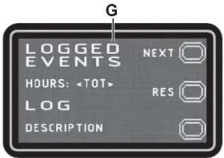
Figure 8
P100870
Operating Time Counter Screen (H, Fig. 9)
This function allows you to check the total accumulated hours of work for each machine subsystem:
- TOTAL counter (machine running time)
- DRIVE counter (drive system usage time)
- BRUSH counter (brush rotation system usage time)
– VACUUM counter (vacuum system usage time)
To return to the main screen (E, Fig. 7), press push-button (A).
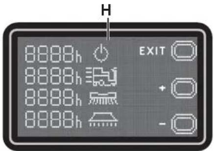
Figure 9
P100871
User Key Management Screen (I, Fig. 10)
This feature allows to determine whether the machine can be used with any user key (factory setting) or only with one or more specific user keys.
– Identification of a specific user key to be used for the machine:
-
Remove the Supervisor key (if any) from the key reader.
-
Place the user key in the key reader and press the push-button (A).
– Removal of a specific user key from the list of keys to be used for the machine:
-
Remove the Supervisor key (if any) from the key reader.
-
Place the user key in the key reader and press the push-button (B).
– Return to factory setting (any user key enabled for the machine):
-
Remove the Supervisor key (if any) from the key reader.
-
Press the push-button (B).
-
Confir rm the operation by pressing the push-button (A).
To return to the user mode screen, press push-button (C).
To return to the main screen (E, Fig. 7), press push-button (A).
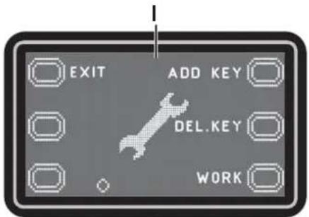
Figure 10
P100871
SQUEEGEE CLEANING

NOTE
The squeegee must be clean and its blades must be in good conditions in order to get a good drying.

CAUTION!
It is advisable to wear protective gloves when cleaning the squeegee because there may be sharp debris.
- Drive the machine on a level floor.
- Ensure that the machine is off and the user key (52) has been removed.
- Loosen the handwheels (32) and remove the squeegee (13).
- Wash and clean the squeegee. In particular, clean the compartments (A, Fig. 11) and the vacuum hole (B). Check the condition of the front (C) and rear (D) blades, ensuring there are no cuts and tears; if necessary, replace them as shown below.
- Install the squeegee in the reverse order of removal.
SQUEEGEE BLADE CHECK AND REPLACEMENT
- Clean the squeegee as shown in the previous paragraph.
- Check the condition of the front (C, Fig. 11) and rear (D) blades, ensuring there are no cuts and tears; if necessary, replace them as shown below. Check that the front corner (E) of the rear blade is not worn; otherwise, turn the blade to replace the worn corner with one of the three remaining intact corners. If the other corners are worn too, replace the blade according to the following procedure:
• Using the tab (F), release and remove the elastic strap (G) from the fasteners (H), then turn or replace the rear blade (D).
• Install the blade in the reverse order of removal. Fasten the elastic strap (G) to the fasteners (H) starting from one side. To make the fastening procedure easier, secure the fasteners one at a time, by locking the strap before the fastener with one hand (M) and pulling it with the other hand (N).
- Unscrew the handwheels (I) and remove the strap (J), then turn or replace the front blade (C).
• Install the blade in the reverse order of removal.
- Install the squeegee (13) and screw down the handwheels (32).
- Lower the squeegee to the floor to check the height of the blades, proceeding as follows:
- Check that the lip (K) of the front blade (C) and the lip (L) of the rear blade (D) are resting as shown in the figure.
- Use the knob (33) to make adjustments.
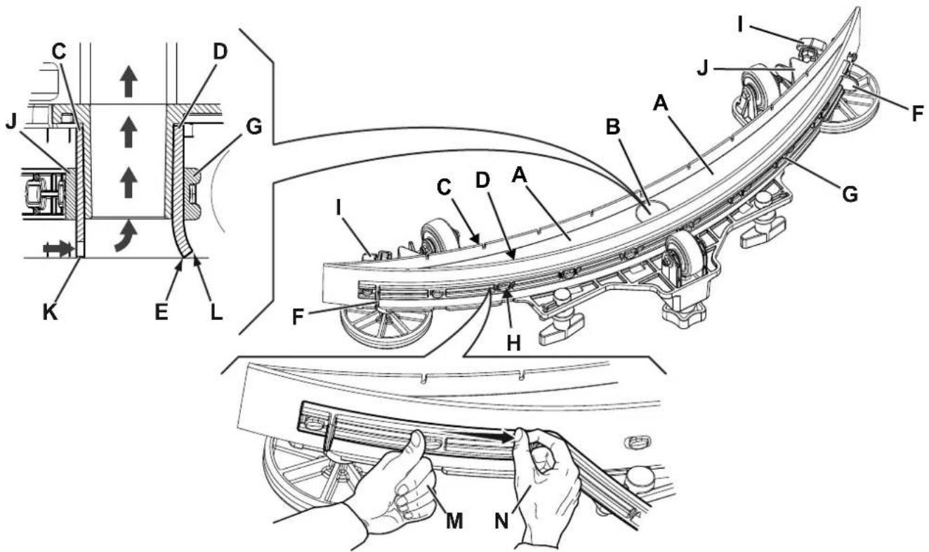
Figure 11
P100850
CLEANING THE BRUSH

CAUTION!
It is advisable to wear protective gloves when cleaning the brush because there may be sharp debris.
- Remove the brush as shown in Use/Operation chapter.
- Clean the brush with water and detergent.
- Check the condition of the brush bristles, ensuring they are not excessively worn; if necessary, replace the brush.
RECOVERY TANK CLEANING
- Drive the machine to the appointed disposal area.
- Ensure that the machine is off and the user key (52) has been removed.
- Raise the cover (18).
- Wash the inside of the tank (17) and the cover with clean water.
- Drain the water in the tank through the hose (26).
- Clean the vacuum grid (28), release the fasteners (A, Fig. 12), open the grid (B) and recover the float (C) then clean it carefully and reinstall it.
- Remove the debris collection tank (D) and open its cover, then clean it carefully and reinstall it on the vacuum hose.
- Check the condition of the tank cover gasket (E).

NOTE
The gasket (E) allows the creation of a vacuum in the tank, which is necessary to suck up the recovery water.
If necessary, replace the gasket (E) by removing it from its housing (F). When fitting the new gasket, position the joint (G) in the lower area, as shown in the figure.
- Check that the seating surface (H) of the gasket (E) is in good condition, clean and suitable to form a seal with the gasket itself.
- Close the cover (18).
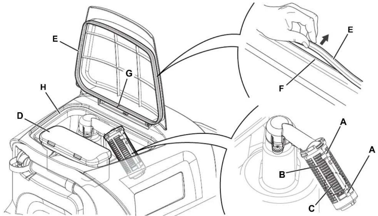
Figure 12
P100873
SOLUTION FILTER CLEANING
- Drive the machine on a level floor.
- Ensure that the machine is off and the user key (52) has been removed.
- Close the solution tank valve (9). The valve is closed when it is in position (9-B) and it is open when it is in position (9-A).
- Remove the transparent cover (A, Fig. 13), retrieve the gasket (B), then remove the filter strainer (C). Wash and rinse them with clean water, then refit them carefully onto the filter support (D).
- Open the valve (9-A).
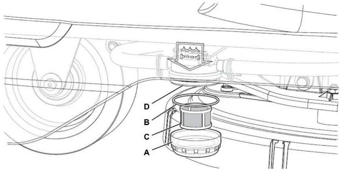
Figure 13
P100874
DETERGENT TANK CLEANING
(For machines with EcoFlex system)
Clean the detergent tank (38) as follows.
- Drive the machine to the appointed disposal area.
- Ensure that the machine is off and the user key (52) has been removed.
-
Lift the cover (29) and check that the recovery tank (17) is empty; if not, empty it using the drain hose (26).
-
Close the cover (18).
-
Grasp the handle (35) and carefully lift the recovery tank assembly (17).
-
Unscrew the cap (A, Fig. 14) from the detergent tank (B).
-
Remove the tank.
-
Rinse and wash out the tank with clean water in the appointed disposal area.
-
Replace the detergent tank (B) as shown in the figure, then refit the plug (A).
-
When the detergent tank has been drained, it may be necessary to drain the EcoFlex system too (see procedure in following section).
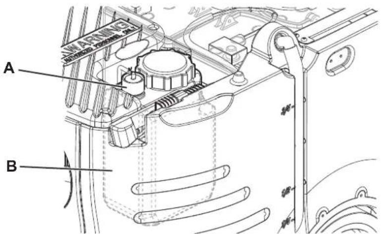
Figure 14
P100875
(For machines with EcoFlex system)
Clean the detergent tank as shown in the previous section.
To remove residual detergent from the detergent hoses and pump, proceed as follows.
- Place the user key (52) in the key reader (41), then press the push-button (42) to start the machine.
- Check that the detergent quantity indicator (50-G) on the display has at least one segment lit.
- Press and hold buttons (46) and (47) at the same time until screen (50-N) appears on the display (after approximately 5 seconds).
- Release buttons (46) and (47) and wait for the countdown timer on the display to finish and the vacuum system to be activated.
- Collect the detergent remained on the floor.
- Turn off the machine with the push-button (42) and remove the user key (52).
- Lift the recovery tank assembly (17), then check that the detergent tank hose (38) is empty, otherwise perform steps 3 to 7 again.

NOTE
The draining cycle lasts about 30 seconds, then the vacuum function automatically turns on, which allows to remove the detergent remained.
The draining cycle can also be performed with the detergent tank (38) full of water, thus cleaning the system thoroughly. It is advisable to perform this type of draining to clean the EcoFlex system from dirt and deposits if the machine has not been used/cleaned for a long time.
The draining cycle can also be performed to quickly fill the detergent supply hose when the tank (38) is full but the system is still empty.
If necessary, the draining cycle can be performed several times in succession.
FUSE CHECK/REPLACEMENT

NOTE
All machine electrical circuits are protected by auto-resettable electronic devices. The safety fuses activates only in case of serious damage.
It is recommended to have the fuses replaced by qualified personnel only.
Refer to the Service Manual available at any Nilfi sk Retailer.
SAFETY FUNCTIONS
The machine is equipped with the following safety functions.
EMERGENCY PUSH-BUTTON
The emergency push-button (5) is located in an easily accessible position. Press it firmly in case of immediate necessity to stop all machine functions.
To reset the machine operation, lift the recovery tank assembly (17) and reconnect the battery connector (6).
ANTI-SKID SAFETY SYSTEM
This system reduces the speed when turning and when the machine tilts laterally to avoid sudden skids, this increasing the machine stability in any condition. The system activation is shown by the icon (51-J) on the display.
DRIVER'S SEAT MICROSWITCH
It is located inside the driver's seat (12) and it does not allow the machine drive system to operate if the operator is not seated on the driver's seat.
ELECTROMAGNETIC BRAKE
It is built-in the rear driving wheels (24) and keeps the machine braked when the machine is off or stopped.
TROUBLESHOOTING
| TROUBLE POSSIBLE CAUSE | REMEDY | |
| The motors are not operating; the display (51) and button LEDs do not turn on. | The battery connector is disconnected. Connect. | |
| The batteries are completely discharged. Charge the batteries. | ||
| The machine does not move and the display (51) shows the alarm:WARNING ALARM T3 | Machine turned on with pedal pressed. Release | the drive pedal.If the problem persists, contact an authorised Service Center. |
| At machine start-up, the button (43) LED fl ashes and the brushes do not work. | Machine switched off without first raising the brush deck. | Wait for the deck to raise before turning the brushes on again by pressing the switch. |
| The brush does not operate; the battery symbol (51-C) border fl ashes and the display shows the alarm message:WARNING ALARM G4 | The batteries are discharged. Charge the batteries. | If the problem persists, replace the batteries. |
| When working, the display shows the alarm message: WARNING ALARM F2 | Brush motor overload. Use a different/less aggressive brush and/or avoid working with extra pressure turned on. | |
| There are foreign materials (tangled threads, etc.) preventing the brush from rotating. | Clean the brush hub. | |
| The display (51) shows the alarm message:WARNING ALARM T2 | Drive motor overload. Turn off the machine and then turn it on again.Avoid using the machine on slopes greater than those indicated or going over excessively tall obstacles. | |
| While recharging the batteries with the on-board battery charger, the display (51) shows the alarm message:WARNING ALARM C4 or C5 | Battery charger not able to correctly recharge the batteries within the maximum time. | Run the battery charging cycle again.If the problem persists, replace the batteries. |
| The display (51) shows an alarm message of the following type:WARNING ALARM XXWhere "XX" is a code other than those listed above. | The machine electronic control system is in alarm condition. | Turn off the machine and then turn it on again.If the problem persists, contact an authorised Service Center. |
| The display (51) shows the alarm message: INVALID SMART KEY | The user key is not enabled. | Add the specific user key to the list of enabled user keys. |
| The dirty water vacuuming is insufficient. | The recovery tank is full. | Empty the tank. |
| The vacuum grid is clogged or the float is stuck closed. | Clean the vacuum grid. | |
| Debris collection filter container clogged. Clean. | ||
| The hose is disconnected from the squeegee. | Connect. | |
| The squeegee is dirty or the squeegee blades are worn or damaged. | Clean the squeegee or overturn/replace the blades. | |
| The tank cover is not properly closed, or the gasket is damaged. | Correctly close the cover or clean/replace the gasket. | |
| The solution flow is insufficient. | Empty detergent solution tank. | Refill. |
| The solution filter is dirty. | Clean the filter. | |
| The EcoFlex system tank (optional) is dirty/encrusted. | Clean with the drain cycle. | |
| The squeegee leaves marks on the floor. | There is debris under the squeegee blades. | Remove the debris. |
| The squeegee blades are worn, chipped or torn. | Overturn or replace the blades. | |
| The squeegee has not been balanced with the handwheel. | Adjust the squeegee. |

NOTE
If the machine has been purchased with an on-board battery charger, the machine cannot operate if this device is not on board. In case of battery charger malfunction, contact an authorised Service Center.
For any further information, contact Nilfi sk Service Centres.
SCRAPPING
Have the machine scrapped by a qualified scraper.
Before scrapping the machine, remove and separate the following materials, which must be disposed of properly according to the
Law in force:
- Batteries
- Brushes
- Plastic hoses and components
- Electrical and electronic components (*)
(*) Refer to the nearest Nilfisk Center especially when scrapping electrical and electronic components.
Machine material composition and recyclability
| Type Recyclable | percentage | SC2000 weight percentage |
| Aluminium 100 % 3 % | ||
| Electric motors - various 29 % 32 % | ||
| Ferrous materials 100 % 23 % | ||
| Wiring harness 80 % 7 % | ||
| Liquids | 100 % 0 % | |
| Plastic - non-recyclable material | 0 % | 3 % |
| Plastic - recyclable material | 100 % 3 % | |
| Polyethylene | 92 % 26 % | |
| Rubber | 20 % 2 % |
INHOUDSOPGAVE
INLEIDING 2
DOEL EN INHOUD VAN DEZE HANDLEIDING....2
BETREFFENDE PERSONEN 2
OPBERGEN VAN DE HANDLEIDING....2
CONFORMITEITSVERKLARING....2
IDENTIFICATIEGEGEVENS 2
ANDERE GEBRUIKERSHANDLEIDINGEN....2
VERVANGINGSONDERDELEN EN ONDERHOUD 2
MODIFICATIES EN VERBETERINGEN....2
BEDRIJFSCAPACITEIT 3
ALGEMENE OPMERKINGEN....3
VERPAKKING VERWIJDEREN/AFLEVERING 3
VEILIGHEID 3
SYMBOLEN OP DE MACHINE 3
SYMBOLEN IN DE HANDLEIDING....4
ALGEMENE INSTRUCTIES 4
BESCHRIJVING VAN DE MACHINE 6
OPBOUW VAN DE MACHINE....6
BEDIENINGSPANEL 8
ACCESSOIRES / OPTIES....9
P100859
P100860
BEDIENINGSPANEEEL
P100861
ACCESSOIRES / OPTIES
- LET OP!
- WAARSCHUWING
- ADVIES
Afbeelding 2
P100864
Afbeelding 3
P100865
flowchart
graph TD
    A["Step 0: Lev. Lev."] --> B["Step 1: Vertical beam with shaded segment"]
    B --> C["Step 2: Vertical beam with shaded section"]
    C --> D["Step 3: Vertical beam with shaded section"]
    D --> E["Step 4: Vertical beam with shaded section"]
    E --> F["Step 5: Vertical beam with shaded section"]
    F --> G["Step 6: Vertical beam with shaded section"]
natural_image
Two overhead diagrams of a car on grid paper, labeled A and B, with arrows indicating motion or movement (no text or symbols beyond labels)Afbeelding 5
P100867


Afbeelding 7
P100869
Afbeelding 8
P100870
Urentellerscherm (H, Afb. 9)
Afbeelding 9
P100871
Beheerscherm bedienerssleutels (I, Afb. 10)
Afbeelding 11
P100850
REINIGING VAN DE SCHIJFBORSTEL

WAARSCHUWING!
Afbeelding 12
P100873