EUP11 - Boiler Morco - Free user manual and instructions
Find the device manual for free EUP11 Morco in PDF.
| Product type | Gas instantaneous water heater |
| Brand | Morco |
| Model | EUP11 |
| Hot water flow rate | 5.5 to 11 litres per minute |
| Temperature rise | Up to 25°C (at maximum flow) |
| Gas supply | Liquefied petroleum gas (LPG) or natural gas depending on version |
| Gas supply pressure | 50 mbar for G31 (depending on configuration) |
| Gas connection | Copper pipe Ø 15 mm |
| Water connection | Cold water inlet on the right, hot water outlet on the left |
| Flue exhaust | Vertical duct Ø 110 mm, minimum total length 600 mm |
| Ignition type | Piezoelectric with pilot light |
| Adjustments | Gas adjustment knob (50-100% power) and water adjustment knob (50-100% flow) |
| Safety devices | Thermocouple, magnetic valve, combustion product safety sensor (anti-fume), hot water limit thermostat |
| Required ventilation | Permanent ventilation openings according to BS EN 1949 (10 cm² per kW of input) |
| Recommended maintenance | At least once a year by a qualified technician: cleaning of the burner, pilot light and heat exchanger |
| Frost protection | Drain the appliance if there is a risk of frost (temperature below 0°C) |
| Dimensions (approx.) | Height 592 mm, Width 314 mm, Depth 244 mm |
| Warranty | 1 year against manufacturing defects (subject to conditions) |
| Intended use | Instantaneous water heating in homes, caravans and boats (adequate ventilation required) |
Frequently Asked Questions - EUP11 Morco
User questions about EUP11 Morco
0 question about this device. Answer the ones you know or ask your own.
Ask a new question about this device
Download the instructions for your Boiler in PDF format for free! Find your manual EUP11 - Morco and take your electronic device back in hand. On this page are published all the documents necessary for the use of your device. EUP11 by Morco.
USER MANUAL EUP11 Morco
natural_image
Technical line drawing of a rectangular appliance with internal components and a handle (no text or symbols)EN INSTALLATION, OPERATION AND MAINTENANCE MANUAL
FR MANUEL POUR L'INSTALLATION ET L'ENTRETIEN
DE INSTALLATIONS-, BETRIEBS- UND WARTUNGSANLEITUNG
IT ISTRUZIONI PER L'INSTALLAZIONE E L'UTILIZZO
ES INSTRUCCIONES PARA LA INSTALACIÓN
Y EL USO
NL MONTAGEHANDLEIDING VOOR DE INSTALLATIE, HET GEBRUIK EN HET ONDERHOUD
EUP6 - EUPII
| CE | 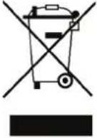 | |
| EN | The device is well built in accordance with the current legislation.The CE sign positioned on the product indicates that it conforms to the following European Directives and Regulation:Regulation Gas Appliance (UE) 2016/426European Standard: gas-fired instantaneous water heaters for the production of domestic hot water EN 26:2015Directive 2009/125/EC Ecodesign requirements for energy-related productsRegulation (EU) 2017/1369 setting a framework for energy labellingDelegated regulation (EU) no. 812/2013Delegated regulation (EU) no. 814/2013 | When the product has reached the end of its serviceable life, it shall be disposed of in an environmentally friendly way and disposed of according to the regulations in force.Separate collection and recycling of the product avoid negative impact for environment and health, and allows recovery of materials, in order to obtain energy and resources saving |
| FR | L'appareil est construit selon les règles de la bonne technique conformément à la loi en vigueur.Le marquage CE placé sur le produit indique qu'il est conforme aux Directives et Règlement Européennes suivantes:Règlement appareils à gaz (UE) 2016/426Directive européenne appareils de production instantanée d'eau chaude pour usages sanitaires EN 26:2015Directive sur les projets éco-compatibles des produits liés à l'énergie 2009/125/CERèglement (UE) 2017/1369 établissant un cadre pour l'étiquetage énergétiqueRèglement délégué (UE) n. 812/2013Règlement délégué (UE) n. 814/2013 | Le produit à la fin de la vie ne doit pas être éliminé avec les déchets municipaux;il doit être remis à un centre de recyclage et éliminé conformément aux réglementations locales.La réception et le recyclage séparé du produit prévient impact négatif pour l'environnement et la santé humaine, permet aussi la récupération de matériaux afin d'obtenir la conservation des ressources naturelles et d'économie d'énergie. |
| DE | Der Einbau dieses Gerätes unterliegt den geltenden technischen Regeln.Das auf dem Gerät angebrachte CE-Markenzeichen deutet darauf hin, dass das Gerät den folgenden europäischen Richtlinien entspricht:Verordnung (EU) 2016/426 über GasverbrauchseinrichtungenEuropäische Norm EN 26:2015: Gasbeheizte Durchlauf-Wasserheizer für den sanitären GebrauchRichtlinie 2009/125/EG zu Anforderungen an die umweltgerechte Gestaltung energieverbrauchsrelevanter ProdukteVerordnung (EU) 2017/1369 zur EnergieverbrauchskennzeichnungDelegierte Verordnung (EU) Nr. 812/2013Delegierte Verordnung (EU) Nr. 814/2013 | Wenn das Produkt das Ende seiner Lebensdauer erreicht hat, ist es umweltgerecht und gemäß den geltenden Bestimmungen zu entsorgen.Durch die getrennte Sammlung und Wiederverwer-tung des Produkts werden negative Auswirkungen auf Umwelt und Gesundheit vermieden und die Rückgewinnung von Materialien ermöglicht, um Energie und Ressourcen zu sparen.Das Symbol der durchgestrichenen Mülltonne weist darauf hin, dass dieses Produkt der Norm zu Elektro- und Elektronikschrott entspricht.Die gesetzwidrige Entsorgung des Produktes durch den Benutzer kann gesetzlich verfolgt werden. |
| IT | L'apparecchio è costruito secondo le regole della buona tecnica nello spirito delle leggi in vigore.La marcatura CE posta sul prodotto indica che lo stesso è conforme alle seguenti Direttive e Regolamenti Europei:Regolamento apparecchi a gas (UE) 2016/426Norma europea apparecchi a gas per la produzione istantanea di acqua calda sanitaria EN 26:2015Direttiva progettazione ecocompatibile dei prodotti connessi all'energia 2009/125/CERegolamento (UE) 2017/1369 che istituisce un quadro per l'etichettatura energeticaRegolamento delegato (UE) n. 812/2013Regolamento delegato (UE) n. 814/2013 | Il prodotto a fine vita non dev'essere smaltito come un rifiuto solido urbano ma dev'essere conferito ad un centro di raccolta differenziata e smaltito secondo le Leggi e le Normative locali vigenti. La raccolta e il riciclo separato del prodotto evita possibili conseguenze negative per l'ambiente e la salute umana, inoltre permette il recupero di materiali di cui è costituito, al fine di ottenere la conservazione delle risorse naturali e significativi risparmi di energia e risorse. Il simbolo del bidone barrato indica la rispondenza di questo prodotto alla normativa relativa ai rifiuti di apparecchiature elettriche ed elettroniche.L'abbandono nell'ambiente di tali apparecchiature o lo smaltimento abusivo delle stesse sono puniti dalla legge. |
| ES | El aparato está construido de acuerdo con las reglas de buenas prácticas en el espíritu de las leyes vigentes. La marca CE colocada en el producto indica que cumple con las siguientes Directivas y Regulaciones Europeas:Reglamento de aparatos que queman combustibles gaseosos (UE) 2016/426Norma europea para aparatos de gas para la producción instantánea de agua caliente sanitaria EN 26:2015Directiva diseño eco-compatible de los productos relacionados con la energía 2009/125/CEReglamento (UE) 2017/1369 que establece un cuadro para el etiquetado energéticoReglamento delegado (UE) n. 812/2013Reglamento delegado (UE) n. 814/2013 | El producto al final de su vida útil no debe desecharse como residuo sólido urbano, sino que debe entregarse a un centro de recogida selectiva y eliminarse de acuerdo con las leyes y las Normativas locales vigentes. La recogida y el reciclaje selectivo del producto evitan posibles consecuencias negativas para el medio ambiente y la salud humana, también permite la recuperación de los materiales con los que está constituido, con el fin de obtener la conservación de los recursos naturales y ahorros significativos de energía y recursos. El símbolo de la papelera tachada indica que este producto cumple con la legislación sobre residuos de equipos eléctricos y electrónicos. El abandono de dichos equipos en el medio ambiente o la eliminación ilegal de los mismos son sancionados por la ley |
| NL | Dit toestel moet geinstalleerd worden volgens de van kracht zijnde voorschriften.Het op het product aangebrachte CE merk geeft aan dat het product voldoet aan de volgende Europese Richtlijnen CE Certificaat:Verordening betreffende gastoestellen (UE) 2016/426Europese norm: gasgestookte doorstroomverwarmers voor de productie van warm water voor huishoudelijk gebruik EN 26: 2015Richtlijn inzake ecologisch ontwerp voor energiegerelateerde producten 2009/125/EGVerordening (EU) 2017/1369 tot vaststelling van een kader voor energie-etiketteringGedelegeerde verordening (EU) nr. 812/2013Gedelegeerde verordening (EU) nr. 814/2013 | Wanneer het product het einde van zijn bruikbare levensduur heeft bereikt, moet het op een milieuvriendelijke manier worden afgevoerd en worden afgevoerd volgens de geldende regelgeving.Afzonderlijke inzameling en recycling van het product vermijden negatieve gevolgen voor het milieu en de gezondheid en maken herstel van materialen mogelijk om energie en hulpbronnen te besparen |
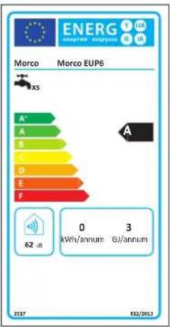
| The appliance complies with the Regulation (EU) 2017/1369.The energy label carries the information regarding the product's energy efficiency characteristics. In this way the end consumer can identify and compare similar products and can make informed choices regarding high efficiency appliances. | |
| L'appareil est conforme à le Règlement (UE) 2017/1369 établissant un cadre pour l'étiquetage énergétique. L'étiquette énergétique indique les informations sur les caractéristiques d'efficacité du produit. De cette manière, le consommateur final a la possibilité d'identifier et de comparer des produits similaires et de pouvoir choisir consciemment des appareils à haute efficacité. | |
| Das Gerät entspricht der Verordnung (EU) 2017/1369. Das Energielabel gibt Auskunft über den Wirkungsgrad des Produkts. Auf diese Weise hat der Endverbraucher die Möglichkeit, ähnliche Produkte zu identifizieren und zu vergleichen und sich bewusst für hocheffiziente Geräte zu entscheiden. | |
| L'apparecchio risponde al Regolamento (UE) 2017/1369 che istituisce un quadro per l'etichetta-tura energetica. L'etichetta energetica riporta le informazioni sulle caratteristiche di efficienza del prodotto. In questa maniera il consumatore finale ha la possibilità di identificare e comparare prodotti simili e di poter operare scelte consapevoli indirizzandosi verso apparecchi ad alta efficienza. | |
| El aparato cumple con el Reglamento (UE) 2017/1369 que establece un cuadro para el etiquetado energético. El etiquetado energético contiene la información sobre las características de eficiencia del producto. De esta manera, el consumidor final tiene la oportunidad de identificar y comparar productos similares y de poder tomar decisiones conscientes dirigiéndose hacia electrodomésticos de alta eficiencia | |
| Het apparaat voldoet aan de Verordening (EU) 2017/1369. Het energielabel geeft informatie over het rendement van het product. Op deze manier heeft de eindverbruiker de mogelijkheid om soortgelijke producten te identificeren en te vergelijken en kan hij bewust kiezen voor hoogrenderende toestellen. |
text_image
ENERG EUP6 Morco EUP6 A* A B C D E F 62 µL 0 kWh/annum 3 GJ/annum 2017 032/2013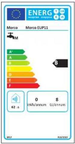
text_image
ENERG Morco EUP11 M A' A B C D E F B 0 8 kWh/annum GI/annum 62.6 2017 8/22/2023PRODUCT DATASHEET - FICHE DU PRODUIT - PRODUCTFICHE - SCHEDA PRODOTTO - FICHA PRODUCTO - PRODUKTDATENBLATT
| Morco | EUP6 EUP11 | ||
| Declared load profile - Profil de charge déclaré - Angegebenes Lastprofil - Profilo di carico dichiarato - Perfil de carga declarado - Aangegeven belastingsprofiel | XS | M | |
| Indoor sound power level - Niveau de puissance sonore interne - Schallleistungspegel in Innenräumen - Livello di potenza sonora all'interno - Nivel de potencia acústica en el interior - Geluidsniveau | dB(A) | 62 62 | |
| Water heating energy efficiency class - Classe d'efficacité énergétique du chauffage de l'eau - Warmwasseraufbereitungs- Energieeffizienzklasse - Classe di efficienza energetica di riscald. dell'acqua - Clase de eficiencia energética del calent. de agua - Energie-efficiëntieklasse voor waterverwarming | A | B | |
| Water heating energy efficiency class - Efficacité énergétique du chauffage de l'eau - Warmwasserbereitungs-Energieeffizienz - Efficienza energetica di riscaldamento dell'acqua - Eficiencia energética del calentamiento de agua - Energie efficiëntie | % | 48 58 | |
| Annual fuel consumption - Consommation annuelle de carburant - Jährlicher Brennstoffverbrauch - Consumo annuo di combustibile - Consumo anual de combustible - Jaarlijks brandstofverbruik | GJ | 3 | 8 |
| Annual consumption of electrical energy - Consommation annuelle d'énergie électrique - Jährlicher Stromverbrauch - Consumo annuo di energia elettrica - Consumo anual de energía eléctrica - Jaarlijks verbruik van elektrische energie | kWh 0 0 | ||
| G31 Nitrogen oxide emissions - Émissions d'oxydes d'azote - Stickoxidemissionen - Emissioni di ossidi d'azoto - Emisiones de óxidos de nitrógeno - Uitstoot van stikstofoxiden | mg/kWh | 29 | - |
| G30 - G31 Nitrogen oxide emissions - Émissions d'oxydes d'azote - Stickoxidemissionen - Emissioni di ossidi d'azoto - Emisiones de óxidos de nitrógeno - Uitstoot van stikstofoxiden | mg/kWh | - 61-20 | |
Cat. I3P (G3I - Propane @ 37 mbar): Belgium (BE), Spain (ES), France (FR), Great Britain (GB), Italy (IT), Holland (NL), Ireland (IE) Cat. I3P (G3I Propane @ 50 mbar) Germany (DE), Austrian (AT)
EUP11
Cat. I3+ (G30/G31 - Butane/Propane @ 28-30/37 mbar): Belgium (BE), Spain (ES), France (FR), Great Britain (GB), Italy (IT), Ireland (IE) Cat. I3P (G31 - Propane @ 37 mbar): Belgium (BE), Spain (ES), France (FR), Great Britain (GB), Italy (IT), Holland (NL), Ireland (IE) Cat. I3B (G30 Butane @ 30 mbar): Belgium (BE), Spain (ES), France (FR), Great Britain (GB), Ireland (IE) Cat. I3P (G31 Propane @ 50 mbar) Germany (DE), Austrian (AT)
| EN | Gas Safety (Installation and Use) Regulations 1998In the interest of safety, it is the law that all gas appliances are installed and serviced by a competent person in accordance with the above regulations, building regulations, codes of practice and byelaws of the local water authority. Failure to comply with the regulations may lead to prosecution. It is in your interests and that of your safety that the law is complied with.Related documentsThe following British Standards, Codes of Practice and other Regulations must be observed in the installation of the water heater.The Gas Safety Regulations (Installation and Use) 1998 The Model Water Byelaws - Byelaws of the Local Water Undertaking - The Building Regulations (Permanent Buildings) England and Scotland - BS 5482 Part I Installations in Permanent Dwellings - Non-Permanent Dwellings BS 5482 Part 3 Installations in Boats - BS EN 1949 Installation of L.P.G. System for Habitational Purposes in Leisure Accommodation Vehicles - BS EN 721 Leisure Accommodation Vehicles - Ventilation Requirements - BS EN ISO 10239 2017 Small Craft L.P.G. Systems | WARNINGThis booklet contains information relevant to the user as well as the installer.In parts of the manual the following symbols are used:WARNING=for actions that require caution and adequate preparationPROHIBITED=for actions that MUST NOT be performedThe water heater package contains:Two knobs to attach to the control panel after installationWater filter to insert in the water valve pipe fitting. |
| FR | Réglementation sur la sécurité du gaz (installation et utilisation) de 1998Dans l'intérêt de la sécurité, la loi stipule que tous les appareils à gaz doivent être installés et soumis à maintenance par une personne compétente conformément aux réglementations ci-dessus, aux règlements de construction, aux codes de conduite et aux règlements des autorités locales des eaux. Le non-respect de ces dispositions peut entraîner des poursuites pénales. Il est dans votre intérêt et dans celui de votre sécurité que la loi soit respectée.Documents connexesLes normes britanniques, codes de conduite et autres règlements suivants doivent être observés lors de l'installation du chauffe-eau : Règlement sur la sécurité du gaz (installation et utilisation) 1998 Règle-ment type relatif à l'eau - Règlement relatif à l'entreprise locale de distribution d'eau - Règlement sur la construction (bâtiments permanents) Angleterre et Écosse - BS 5482 Partie I Installations dans des logements permanents - Logements non permanents BS 5482 Partie 3 Installations sur des embarca-tions - BS EN 1949 Installation de systèmes GPL à usage résidentiel dans les véhicules d'hébergement de loisirs - BS EN 1949 BS EN 721 Véhicules d'hébergement de loisirs - BS EN 721 Véhicules d'héber-gement de loisirs - Exigences en matière de ventilation - BS EN ISO 10239 2017 Systèmes G.P.L. pour petites embarcations. | AVERTISSEMENTSCette notice contient des données et des informations destinées à la fois à l'utilisateur et à l'installateur.Dans certaines parties du manuel, les symboles suivants sont utilisés:ATTENTION=pour des actions qui requièrent une précaution particulière et une préparation adéquateINTERDIT=pour des actions qui NE DOIVENT absolu-ment PAS être exécutéesDans l'emballage du chauffe eau se trouvent:2 boutons à fixer au panneau de commande après l'installationI filtre à eau à insérer dans le raccord d'entrée de la vanne de l'eau. |
| DE | Sicherheitsbestimmungen für den Umgang mit Gas (Installation und Betrieb) von 1998Im Interesse der Sicherheit ist es gesetzlich vorgeschrieben, dass alle Gasgeräte von Fachpersonal gemäß den obigen Bestimmungen, Bauvorschriften, Verhaltensregeln und Verordnungen der örtliche Wasserbehörden installiert und gewartet werden. Die Nichtbeachtung der Bestimmungen kann recht-liche Folgen haben. Es liegt in Ihrem Interesse und dem der Sicherheit, dass das Gesetz beachtet wird.Zugehörige DokumenteFolgende Britische Standards, Verhaltensregeln und weitere Bestimmungen sind bei der Installation des Warmwasserbereiters zu beachten: The Gas Safety Regulations (Installation and Use) 1998 The Model Water Byelaws - Byelaws of the Local Water Undertaking - The Build-ding Regulations (Permanent Bu-ildings) England and Scotland - BS 5482 Part 1 Installations in Permanent Dwellings - Non-Permanent Dwellings BS 5482 Part 3 Installation auf Booten - BS EN 1949 Installation von Flüssiggasanlagen in bewohnbaren Freizeitfahrzeugen und zu Wohnzwecken - BS EN 721 Bewohnbare Freizeitfahrzeuge. Anforderungen an die Sicherheitslüftung - BS EN ISO 10239 2017 Kleine Wasserfahrzeuge. Flüssiggas-Anlagen (LPG) | HINWEIDas vorliegende Handbuch ist für den Betreiber und den Installa-teur bestimmt.In einigen Kapiteln des Handbuchs werden Symbole verwendet:ACHTUNG=Vorgänge, für die besondere Vorsicht und eine geeignete Ausbildung erforderlich sindVERBOTEN=Vorgänge, die STRENG VERBOTEN sindIn der Verpackung des Gas-Durchlauferrhitzers befinden sich:Drehknöpfe zur Befestigung an der Schalttafel nach der Installa-tionWasserfilter zum Einsetzen in den Anschluss des Wasserzu-flussventils. |
| IT | Normativa sulla sicurezza del gas (installazione e uso) del 1998Nell'interesse della sicurezza, è legge che tutti gli apparecchi a gas siano installati e sottoposti a manu-tenzione da una persona competente in conformità con le suddette normative, regolamenti edilizi, codici di condotta e regolamenti dell'autorità idrica locale. Il mancato rispetto delle norme può comportare l'azione penale. É nel tuo interesse e in quello della tua sicurezza che la legge sia rispettata.Documenti correlatiI seguenti Standard Britannici, Codici di Condotta e altri Regolamenti devono essere osservati durante l'installazione dello scaldacqua: The Gas Safety Regulations (Installation and Use) 1998 The Model Water Byelaws - Byelaws of the Local Water Undertaking - The Building Regulations (Permanent Buildings) England and Scotland - BS 5482 Part I Installations in Permanent Dwellings - Non-Permanent Dwellings BS 5482 Part 3 Installazioni su imbarcazioni - BS EN 1949 Installazione di impianti G.P.L. per scopi abita-tivi in veicoli per strutture ricettive per il tempo libero - BS EN 721 Veicoli per strutture ricettive per tempo libero - Requisiti di ventilazione - BS EN ISO 10239 2017 Sistemi G.P.L. per piccole imbarcazioni | AVVERTENZAQuesto libretto contiene dati ed informazioni destinati sia all'utente che all'installatore.In alcune parti del manuale sono utilizzati i simboli:ATTENZIONE=per azioni che richiedono particolare cautela ed adeguata preparazioneVIETATO=per azioni che NON DEVONO essere asso-lutamente eseguiteNell'imballo dello scaldabagno si trovano:manopole da fissare al pannello di comando dopo l'installazioneI filtro acqua da inserire nel raccordo di ingresso della valvola acqua. |
| ES | Normativa de seguridad del gas (instalación y uso) de 1998En aras de la seguridad, la ley establece que todos los aparatos de gas sean sometidos a instalación y mantenimiento por una persona competente de acuerdo con las normativas, los reglamentos de la construcción, los códigos de conducta y los reglamentos de la autoridad local de suministro de agua.El incumplimiento de las normas puede dar lugar a una acción penal. El cumplimiento de la ley es por su interés y su seguridad.Documentos relacionadosSe deben observar las siguientes normas británicas, códigos de conducta y otras regulaciones al instalar el calentador de agua: Regulaciones de seguridad del gas (Instalación y uso) 1998 Estatutos modelo de agua - Estatutos de la empresa local de agua - Regulaciones de construcción (Edificios permanentes) Inglaterra y Escocia - BS 5482 Parte I Instalaciones en viviendas permanentes - Viviendas no perma-nentes BS 5482 Parte 3 Instalaciones en embarcazioni - BS EN 1949 Instalación de sistemas GLP para usos residenciales en vehículos para estructuras de alojamiento para el ocio - BS EN 721 Vehículos para estructuras de alojamiento para el ocio - Requisitos de ventilación - BS EN ISO 10239 2017 Sistemas GLP para embarcazioni pequeñas. | ADVERTENCIAEste folleto contiene datos e información destinados tanto al usu-rio como al instalador.En algunas partes del manual se utilizan los símbolos:ATENCIÓN=para acciones que requieren especial pre-caución y una preparación adecuadaPROHIBIDO=para acciones que NO DEBEN realizarse bajo ningún conceptoEn el embalaje del calentador de agua encontrará:2 perillas para fijar al panel de control después de la instalaciónI filtro de agua para insertar en el racor de entrada de la válvula de agua. |
| NL | Gasveiligheidsvoorschriften (installatie en gebruik) uit 1998In het belang van de veiligheid schriftt de wet voor dat alle gastoestellen door een bevoegd persoon moeten worden geïnstalleerd en onderhouden in overeenstemming met de bovengenoemde voorschriften, bouvvoorschriften, praktijkcodes en verordeningen van de plaatselijke watermaatschappij Niet-naleving van de voorschriften kan leiden tot strafrechtelijke vervolging. Het is in uw eigen belang en dat van uw veiligheid dat de wet wordt nageleefd.Gerelateerde documentenDe volgende Britse normen, praktijkcodes en andere voorschriften moeten bij de installatie van de geiser in acht worden genomen: The Gas Safety Regulations (Installation and Use) 1998 The Model Water Byelaws - Byelaws of the Local Water Undertaking - The Building Regulations (Permanent Buildings) England and Scotland - BS 5482 Part I Installations in Permanent Dwellings - Non-Permanent Dwellings BS 5482 Part 3 Installations op boten - BS EN 1949 Installatie van LPG-installations voor woondoeleinden in voertu-gen voor vrijetijdsbesteding - BS EN 721 Voertuigen voor vrijetijdsbesteding - Ventilatie-eisen - BS EN ISO 10239 2017 LPG-systemen voor kleine boten | WAARSCHUWINGDeze handleiding bevat gegevens en informatie bestemd zowel voor de gebruiker als voor de installateur.In de handleiding worden op een aantal plaatsen de volgende symbolen gebruikt:LET OPI=voor handeling die bijzondere zorg enadequate voorbereiding vereisenNIET TOEGESTAAN=voor acties die NIET MOGEN worden uitgevoerdIn de verpakking van de geiser bevinden zich:knoppen die na de installatie op het bedieningspaneel moeten worden bevestigdI waterfilter dat in de inlaataansluiting van de waterklep moet worden geplaatst |
EN
INDEX
GENERAL SAFETY WARNINGS 6
DESCRIPTION OF THE APPLIANCE 6
INSTALLATION 6
Regulations 6
Wall mounting 6
Room ventilation 6
Gas connection 7
Water connection 7
Flue gas 7
Flue gas release safety device 7
OPERATION 7
Function 7
Usage 7
MAINTENANCE 8
Removing the casing 8
Troubleshooting: problems and solutions 8
FOR THE ENGINEER 9
WARRANTY 9
TECHNICAL DATA 30
FR
INDEX
AVERTISSEMENTS GÉNÉRAUX DE SÉCURITÉ 10
DESCRIPTION DE L'APPAREIL 10
INSTALLATION 10
Règlements 10
Montage mural 10
BESCHRIJVING VAN HET APPARAAT 26
INSTALLATIE 26
Voorschriften 26
Wandmontage 26
The Operation Manual is an integral part of the product and so must be carefully preserved in order to accompany the product; if it is lost or damaged another copy can be requested from Morco Products Limited on 01482 325 456 or visit our website www.morcoproducts.co.uk.

The installation of the device and any other repairs or maintenance must be performed by Gas Safe Engineer or other qualified personnel according to the law in force, in compliance with the installing regulations including any revisions.

A Gas Safe Engineer or other qualified personnel must commission this device.

The device must be used according to the manufacturer specifications. The manufacturer cannot be held contractually or otherwise responsible for damage caused to persons, animals or objects as a result of incorrect installation, repair or maintenance or improper usage.

The product's safety or automatic regulation devices must not be modified unless performed by the manufacturer.

This device is intended for heating water and therefore must be connected to a water distribution network who's load and settings are compatible with the product.

If water leaks are observed, turn off the water supply and advise a Gas Safe Engineer or other qualified personnel.

If the appliance is not used for prolonged periods turn off the gas supply. If there is a risk of the water freezing, empty the water heater. Please see “frost and freezing” on page 7.

If the machine breaks down or does not function properly, deactivate it, do not attempt to perform any repairs and contact a Gas Safe Engineer or other qualified person.

The appliance should be maintained at least once a year.

When the product has reached the end of its serviceable life, it shall be disposed of in an environmentally friendly way; ensuring that the majority of the product is fully recycled
When using the device the following safety rules must be applied:

Do not use the machine for purposes other than those intended by the manufacturer.

Do not block the intake, flue or the ventilation openings in the area where the device is installed with rags, paper or any other materials.

If a gas leak is detected, do not switch on any electrical devices, telephones or any other objects that could produce a spark. Ventilate the area by opening the doors and windows and switch off the gas supply.

Do not place objects on top of the device.

Do not leave flammable containers or substances in the area where the device is installed.

Children or inexperienced persons are prohibited from using the device.
DESCRIPTION OF THE APPLIANCE
The Morco EUP6 and EUPII are an open flued 6 and 11 litre instantaneous gas water heater.
The air for combustion comes from the external vents in the cupboard that the heater is placed in and hence very careful attention must be paid to providing sufficient ventilation.
See section Room Ventilation.
The appliance is suitable for use in dedicated boiler cupboards in caravan holiday homes.
The appliance relies on a pilot flame to ignite the main burner once a hot tap is opened.
The appliance does not store hot water.
The flow of the water through the appliance can be adjusted from 3 to 6 litres per minute (EUP6 model) and 5.5 to 11 litres per minute (EUPII model) and this corresponds to the temperature of the incoming water being increased by 50°C or 25°C respectively. This adjustment is made via the water temperature adjustment knob and during winter months it is advisable to move the knob fully clockwise to ensure hot water of an acceptable temperature.
INSTALLATION
Regulations
The use of gas devices is controlled by precise regulations.
Installation of liquid petroleum gas (L.P.G) must comply with all the manufacturer's requirements and those of the regulations.
Wall mounting
Warning
Do not install this device in an area that contains dust, greasy vapour and/or corrosive elements.
- The device must be installed on a suitable wall surface that allows the fitting of a vertical exhaust gas flue
- It is vital to leave the minimal distances around the device as shown in fig 2 (pag. 33) to allow for maintenance operations to take place.
Location
The water heater requires a plentiful supply of fresh air for correct operation. Fixed ventilators or air inlets should not be obstructed.
Do not install the water heater in a location where incomplete combustion is foreseeable such as bathrooms or bedrooms unless specifically allowed by national legislation.
The minimum low and high level free ventilation areas are stated on this page and must be observed.
The water heater must be fixed to a load bearing wall in a vertical plane.
Room ventilation
The installation of the water heater must comply with regulations in force including any updates (see page 4).
Warning: This device can only be installed in venues that are permanently ventilated according to regulation in force.
• COMBUSTION GAS REMOVAL
A single wall vertical flue pipe of ∅90 (for EUP6) and ∅110mm (for EUPII) must be used and when it passes through combustible materials, a metal sleeve of ∅170mm must be used to allow an air gap of 25 mm. Part codes FTFCT (for EUP6) and FTFCTRIMG101 (for EUPII).
Flue pipes and terminals should comply with BS 715. Terminals shall not be sited within 300 mm. of a ventilator or open window. In the U.K. full details of flueing requirements are given in BS EN 1949.
The overall length of the flue must be 600mm from the bottom of the terminal louvres to the top of the water heater. At least 250mm of this length must be external to the roof through which it is fitted.
• AIR SUPPLY FOR COMBUSTION
Air requirements: Reference is made to BS EN 1949 and EN 721 covering ventilation requirements for permanent dwellings, caravans and boats.
Fixed ventilation should be provided to avoid draughts as far as possible without impairing the free area of ventilation, even in adverse weather conditions. If the heater is positioned in location which may be subjected to strong draughts i.e. close to a window or opening then strong draughts or gusts of wind may extinguish the pilot.
All permanent openings for ventilation should be designed to pre-vent the entry of vermin. Where screens are provided, they should not have apertures of less than 6 mm. or greater than 9 mm. in any direction, and they should be accessible for cleaning. Fine mesh screens shall be avoided as they are liable to become blocked with dust.
The location of vents and the method of cleaning them should be stated in the Owners Handbook (Caravans and Boats).
As a guide, the minimum effective free area of vents is stated below in connection with this water heater. Additional appliances burning gas in the same area would require additional ventilation.
If the appliance is installed in an enclosed cupboard in a Caravan Holiday Home the required ventilation is that specified in BS EN 1949, i.e. 10 cm ^2 per kilowatt input rating divided between high and low.
Gas connection
The water heater should be connected to the gas supply via a 15mm diameter copper gas pipe. A gas isolation valve must be fit- ted to the gas inlet on the water heater.
When installing or commissioning the water heater the following must be observed:
- The diameter of the gas pipe between the supply bottle or tank must be in accordance with the regulations in force
- The regulator size and pressure specification are correct for the application
- The correct gas (L.P.G.) is being supplied
- All the required gas pressure and tightness tests are carried out as part of the commissioning process.
- Gas joints downstream of the magnetic gas valve must be checked with leak detection fluid while the heater is running
- Gas jointing paste should not be used when connecting the gas isolation valve
Do not obstruct the area's ventilation openings where the device is installed to avoid dangers such as the build-up of toxic and explosive gases.
ATTENTION: if the appliance is supplied with G31@50 mbar, remove the protective cap (pos. 10 page 32 water heater components) and regulate the pressure screw so that the burner reaches the pressure indicate in the technical data.
Water connection
Connect the water heater to the water supply.
From the front, the cold water input is on the right and the hot water output is on the left.

Insert the filter into the water valve input fitting.

Remove the plastic cap from the hot water output fitting before connecting it to the water supply.
Flue gas
For output of flue gases refer to the regulations in force including any updates. See page 4.
The water heater must be connected to a suitable flue terminal. The following must be observed:
- The flue must be installed vertically – through the roof of the holiday home
- The diameter of the flue terminal must match that of the water heater (90 mm for EUP6 and 110mm for EUP11)
- The overall flue length from the top of the water heater to the top of the external flue must be at least 600mm. The distance from the external roof surface to the top of the external flue must be at least 250mm.
Flue gas safety device
This product is equipped with a flue gas safety device. The device ensures the flue gases leave the water heater safely via the flue. The flue safety device is a flue gas safety device that will interrupt the flow of gas to the water heater burner and pilot light in the event that there is a total or partial blockage in the flue that does not allow the flue gases to leave safely. The device will also operate if the design or length of the flue is not correct. This stat will reset when it has cooled down due to the technical issue being resolved thus allowing the water heater to operate as normal. If the flue gas safety device is faulty it will need to be replaced before the water heater will function again. The stat must not be removed or altered in any way otherwise the operation of the water heater may become dangerous.
OPERATION
Function
The water heater is designed to produce instantaneous hot water. The hot water is delivered to several outlets around the home. If more than one outlet is used at any one time the delivery of hot water will be reduced at each outlet. The Water heater has 2 main controls:
- A gas control knob - "A" in fig 4 page 35
- A water temperature control knob – “B” in fig 4 page 35
The minimum gas level (fig. 4) will provide approximately 50% of the available power. Turning the gas control knob counter-clockwise will increase the power level between 50% and 100%. This function may be useful to vary the temperature of the water supplied.
The water temperature selector allows water to be supplied anywhere between 50% and 100% of the water heater's capability. In effect the selector reduces the water flow through the heater to the taps to increase the water temperature and correspondingly increases the water flow to reduce the water temperature.
In the UK the normal positions for the controls are:
- Gas control – always set to 100% (fully counter clockwise)
- Water control set to 100% (fully clockwise) during the winter months
- Water control set to between 100% and 50% during the summer months to suit the customer's preference for hot water temperature
Usage (fig. 4 page 35)
Ensure that the appliance gas isolation valve and all water taps are switched off
- Turn on the main external gas supply on the bottle or tank
- Light other gas appliances such as the cooker hob or fire and allow them to run for 30 seconds- this is to purge the gas system of air
- Open the appliance gas isolation valve, placed immediately below the water heater on the gas input pipe
- Rotate knob A to the pilot position (★), press the knob down all the way and keep it pressed
- Press the piezo electric button that is located under the water heater until the spark ignites the pilot flame. The flame can be seen through the viewing hole on the front of the heater by looking slightly upwards and to the left. When it ignites, keep the gas control knob ("A"), pressed for 20-30 seconds. If the pilot does not stay lit when the knob is released, repeat the procedure
- Rotate knob A towards the large flame (A) during rotation it is necessary to keep the knob pressed down lightly until the final position is reached
- From this moment the device is able to produce hot water on request. Opening the hot water tap causes the main burner to be ignited, and inversely, by closing the hot water tap the main burner is switched off; but the pilot flame remains switched on for future requirements
- If the main burner or pilot flame is accidentally turned off, the gas valve automatically blocks the output of gas within 60 seconds so to avoid any danger. To return the device to an operational mode, repeat the steps above
The machine is switched off by rotating knob A to the (● OFF) position. When the water heater is not used for long periods close the appliance gas isolation valve or the L.P.G. gas valve on the bottle/tank. For the best operational results it is recommended to have a Gas Safe Engineer or other qualified technician service the machine at least once a year.
PRECAUTIONS TO BE TAKEN AGAINST FROST AND FREE-ZING CONDITIONS
If there is a possibility that the area where the appliance is installed could reach below 0^ C, the device must be emptied of all water.
During cold spells, if your appliance is located in a place exposed to frost and freezing conditions, it must be drained down in the following way:
- Turn off the home's water inlet stop tap.
- Disconnect the water supply pipe from the home
- Open any drain cocks located on the hot/cold water pipework under the home
-
Turn on all hot and cold water taps
-
Turn appliance water temperature selector fully anticlockwise
- Disconnect the cold water inlet to the water heater
- Full details of winterisation can be found under “troubleshooting” at www.morcoproducts.co.uk
- A summary can be found on page 9 of this manual.
To use the appliance again reverse the above procedure
MAINTENANCE
To maintain the machine at maximum efficiency, have a Gas Safe Engineer or other qualified personnel perform a maintenance check at least once a year.
Before cleaning or performing maintenance, opening or disassembling the panels, switch off the device and turn off the gas supply. Check the main burner and the pilot flame, the ignition electrode, the safety valve and that there is no gas or water leakage. Check that there is nothing obstructing the passages within the heat exchanger or flue
To clean the outside of the panels utilize a cloth with soap and water.
Do not use solvents, powders or abrasive sponges.
Do not clean the device and/or its parts with flammable materials (e.g. petrol, alcohol, diesel etc.).
Removing the casing
To remove the outer casing follow the steps below:
- Remove the selector knobs (C and D fig. 5 page 35)
- Remove the screws (E fig. 5 page 35)
- Pull the bottom of the casing forwards until clear of the gas/water spindles
- Shift the casing upwards to free it from the upper and lateral hooks
- Shift the casing forwards
- To reinsert the casing, follow the above steps in reverse order
TROUBLESHOOTING: PROBLEMS AND SOLUTIONS
For the best functioning of the water heater, to prolong its lifetime and ensure that it is always safe, it should be inspected at least once a year by a Gas safe engineer.
The Gas safe engineer is to perform the following maintenance operations:
- Remove any rust from the burner
- Remove any deposit from the electrodes
- Clean the combustion chamber
- Check the ignition, switching off and general functionality of the device
- Check that the gas and water pipes and connections are sealed
Warning: the flowing repair instructions are only to be performed by Gas Safe Engineers or other qualified and authorized technicians.
| PROBLEM CAUSE SOLUTIONS | ||
| There is no spark - appliance spark wire is disconnected- piezoelectric mechanism broken- the electrode is damaged | - reconnect- test, replace- replace | |
| The pilot does not switch on when there is a spark | - pilot injector blocked- electrode activation position needs changing- no gas supply- air in the gas tubes | - clean by immersing in solvent or replace- adjust- open the appliance gas isolation valve- purge air by turning on all gas rings on hob for 30 seconds |
| The pilot does not stay on - thermocouple faulty | - broken magnetic valve- flue sensor faulty or activated | - replace- replace- check flueing/ventilation- replace |
| Pilot on but the main burner does not ignite - insufficient water pressure- the diaphragm is broken | - Increase the external water supply pressure- rotate the knob B counter clockwise- replace | |
| The burner does not switch off when the water turns off | - contamination on the gas valve seat- gas valve push rod is locked in the open position- check the gas pressure | - test, clean- Check the correct operation of the cold water push rod , dis-assemble, clean or replace- if the inlet gas pressure exceeds the specification replace the pressure regulator on the external bottle or tank |
| Delayed burner activation - pilot burner flame | is too far from main burner flame or it is too short | - check inlet gas pressure, clean injector and pilot burner |
| The heat exchanger fins becomes sooty in a small amount of time | - poor draught, adverse weather conditions or dusty surroundings- yellow flame- excess gas consumption | - check the flue installation- check the gas type and clean the burner- check gas pressure and adjust |
FOR THE ENGINEER - STARTING UP THE APPLIANCE AND FINAL CHECKS
Start the appliance by following the directions given in section "Usage" page 7, checking that the appliance is working correctly. Pay special attention to the colour of the flames ensuring there is no yellow-ness which would indicate burner venturis blocked by insect matter.
Check the gas operating pressures with the heater under full power at the inlet pressure nipple located on the right hand side of the gas body valve stem.
Check the burner pressure with the heater at full load at the test nipple located on the left hand side of the main gas valve body be- low the main burner. These pressures must at least be equal those specified in this manual in order to achieve the desired performance specified in this manual.
These gas water heaters are set in the factory for use with the gas they are intended to burn. The gas for which each appliance is set is indicated on the packaging and on the data plate of the heater itself
Check the flue for spillage: close all the doors and windows in the room containing the water heater. If there are any fans or extractors in the room then these must be turned on full. Light any other open flued appliances such as fires of gas hobs. Turn the water heater on by opening a hot tap on full burn and run for 5 minutes to allow the flue to warm up.
Hold a smoke match to the side of the opening of the draught diver- tor using an extended holder, making sure that the end of the match is located centrally in the draught divertor.
The smoke should be pulled up the flue and not back into the room. If spillage is detected, run the appliance for a further 10 minutes and then repeat the test. If spillage is still detected then check the flue for blockages, check that the correct flue terminal is fitted and that the correct ventilation is fitted at a low and high level. Also check the ventilation has not been blocked.
LOOKING AFTER THE APPLIANCE
- PRECAUTIONS
- Against furring up (lime scale)
If the appliance is installed in an area with very hard water, with time, the following may occur:
– A fall in the hot water temperature, or
– A reduction in the hot water flow.
This means that the heat exchanger may be furred up, creating the above situations. Note: De-furring/descaling should be carried out using proprietary agent or dilute hydrochloric acid. It is recommended to circulate the descaling fluid around the heat exchanger in order to speed up the process.
Gas water heaters are rugged pieces of equipment which are designed to work for a long time with minimum maintenance requirements. The only regular maintenance required is the (annual) cleaning of the heating body and the burner. If the appliance is installed in a caravan it is advised that this is done at the beginning of each season.
• CLEANING THE MAIN BURNER
To carry out the annual cleaning of the burner, proceed as follows:
– Turn off the gas supply, remove the cover and remove the burner.
- Clean the surface of the burner heads gently with a brush and vacuum cleaner. Then blow through them to remove any particles of dust loosened du-ring the brushing operation.
- Check the venturis in the main burner for contamination from insects and spiders webs.
• CLEANING THE HEAT EXCHANGER
To carry out the annual cleaning of the heating body, proceed as follows:
– Turn off the gas supply
- Turn off the supply of water to the appliance by turning off the appliance water supply.
- Turn on all the hot water taps to empty all the pipes.
- Remove the heating body and clean it by gently brushing the fins. Soot, if found, should be removed by washing, and the cause of the sooting investigated.
• CLEANING THE PILOT
If the pilot light flame is yellow and the safety valve takes a long time to open, this means that either the pilot injector or pilot burner is partially blocked.
The pilot injector may be blocked with contaminants carried within the gas, whilst the pilot burner is more likely to be contaminated by insects (spiders / egg sacs)
N.B. No attempt should be made to clear blocked or partially blocked pilot injectors by using wire. If blowing through the injector or immersing in solvent fails to clear the restriction, then a new injector should be fitted.
When the pilot is working normally the flame should be a stable blue coloured cone shape. To clean the pilot burner, proceed as follows:
- Turn off the gas supply, remove the front cover. Remove the pilot injector, by slackening the supply pipe nut first, and unscrewing the pilot injector from the pilot burner
- Remove the contamination from within the pilot burner using a pipe cleaner, and blow through to remove any further debris.
- Replace the pilot injector, ensuring that the washers are properly fitted.
WINTERISATION
Winterisation of Holiday Homes That Have a Water Heater
Fresh water freezes at 0^ C and expands by 9% with a significant force that will destroy:
- Pipe work
• Water heater components
• Taps, and shower valves
DRAIN DOWN
If you leave fresh water in your caravan system over the winter you will run the risk of damage. This can only be avoided by removing the fresh water from the system – we call this a “drain down”. You may wish to drain down the fresh water system yourself using the procedure in the next section but we STRONGLY RECOMMEND that you have this carried out by an experienced engineer as many caravan systems can only be completely drained by blowing the water out and this requires specialist equipment. View the charge for a drain down as a mini insurance policy and always ask the engineer if he has the equipment to blow the water out. The two most common parts to be damaged by frost on a water heater are the water control assembly and heat exchanger and the shower valve can also be damaged by frost and the costs to replace these can be expensive, see our website for water heater spare prices.
Drain Down Procedure – without specialist equipment
- Turn off the fresh water supply stop cock outside the Holiday Home
- Disconnect the fresh water feed outside the home if possible as this protects from flooding due to stop cock failure
- Open all hot and cold taps and shower valves and place the shower head in the tray
- Use the Holiday Home Owner's Handbook to locate all the fresh water drain cocks under the van – some of these may not be obvious
- Open these drain cocks
This procedure does not guarantee that all the fresh water will leave the system. Most modern homes have double check valves in the TMV2 shower mixers and these trap fresh water and stop the flow of water around the system once the drain cocks and taps are open. It may appear that all the water has left the system, but beware! This pitfall can be avoided by removing the shower mixer valve/valves from the system after the cold water supply has been switched off and the drain cocks opened. Many manufacturers provide access panels and these may make the removal of shower mixers easier. Removal of some shower mixers requires the use of special tools. In addition, pipe work layouts can cause air locks leaving water inside vulnerable components such as the water heater or shower mixer.
Re-commissioning the home is a reverse of the above procedure.
This drain down procedure may work but the only way to be sure is to blow the water out using compressed air at 3 bar maximum pressure.
WARRANTY
The water heater is guaranteed against manufacturing defects for one year from first commissioning date. However the guarantee is subject to proof of commissioning in accordance with the gas safety (Installation and Use) act of 1998. The guarantee does not cover defects caused by lack of maintenance. Morco Products Ltd. warranty will cover parts and labour if the appliance has been fitted as part of the original equipment in a caravan holiday home or leisure accommodation vehicle.
Appliances distributed as non original equipment either directly from Morco Products Ltd. or other merchants are subject to a return to base policy for repair and return.
As an alternative to returning the appliance for repair we will supply spare parts and advice for defective appliances on the provision that we can talk to the competent registered gas safe engineer involved in the fitting or repair of the defective appliance. Under this approach, no compensation will be offered for labour involved in the removal and refitting of the appliance or for any work / travelling involved in the fitting of spare parts. Exclusions from warranty
- Damage caused by frost
- Scaling up of the heat exchanger
- Blocked pilot injectors
- Insect or debris in the burner or heat exchanger
- Blocked gas or water filters
- Incorrect operation caused by damaged mixer taps or shower TMV2
- Incorrect installation of the appliance or flue
- Low water pressure
Please note that proof of commissioning for the purposes of this warranty is a copy of the commissioning certificate as filled out by the Gas Safe Engineer or other qualified personnel.
FR
AVERTISSEMENTS GÉNÉRAUX DE SÉCURITÉ
- Light other gas appliances such as the cooker hob or fire and allow them to run for 30 seconds- this is to purge the gas system of air
BESCHRIJVING VAN HET APPARAAT
text_image
Technical diagram of a mechanical device with numbered components for identificationEN FR
natural_image
Technical line drawing of a rectangular industrial vessel with labeled ports (no text or symbols beyond labels)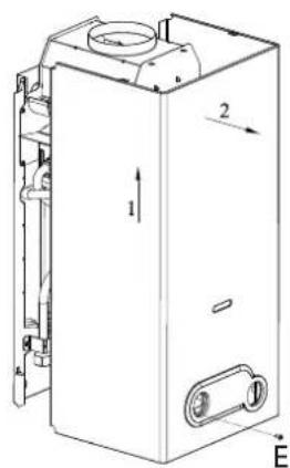
text_image
Technical diagram of a mechanical device with labeled components and directional arrows5
MORCO
Supplied by Innovita Italy
Distributed in U.K. by:
MORCO PRODUCTS LTD
Morco House
Riverview Road
Beverley
East Yorkshire
HUI7 0LD
ENGLAND
Telephone Number: 01482 325456
Fax Number: 01482 212869
Web Address: www.morcoproducts.co.uk