
HM400 - Oscilloscope HAMEG - Free user manual and instructions
Find the device manual for free HM400 HAMEG in PDF.
| Product type | Analog oscilloscope 40 MHz |
| Brand and model | HAMEG HM400 |
| Bandwidth (-3 dB) | DC to 40 MHz (5 mV/div to 20 V/div) ; DC to 10 MHz (1 mV/div to 2 mV/div) |
| Rise time (calculated) | < 8.75 ns (5 mV/div to 20 V/div) ; < 35 ns (1 mV/div to 2 mV/div) |
| Deflection coefficients | 1 mV/div to 20 V/div in 1-2-5 sequence, ±3% to ±5%; variable up to 50 V/div |
| Time base | 100 ns/div to 0.2 s/div in 1-2-5 sequence, ±3%; x10 expansion up to 10 ns/div |
| Input impedance | 1 MΩ // 15 pF |
| Maximum input voltage | 400 V (DC + AC peak) |
| Trigger modes | Automatic with peak detection, normal; sources: CH1, CH2, line, external; couplings AC, DC, LF, TV |
| Display | CRT 8 x 10 div, acceleration voltage 2 kV |
| Component tester | Test voltage 7 Vrms, current 7 mArms, frequency 50 Hz |
| Configuration memories | 6 configurations (Save/Recall) |
| Probe Adjust output | Square wave 1 kHz or 1 MHz, 0.2 Vpp, rise time <5 ns |
| Power supply | 105-253 V, 50/60 Hz ±10%, CAT II |
| Power consumption | Approximately 30 W at 230 V/50 Hz |
| Dimensions (W x H x D) | 285 x 125 x 380 mm |
| Weight | 4.8 kg |
| Safety | Complies with EN 61010-1, CAT I, pollution degree 2 |
| Maintenance and cleaning | Clean with a damp cloth (water + 1% detergent); for the screen, use water or petroleum ether; do not allow liquid to enter |
| Repairability | HAMEG after-sales service, RMA number required before return |
| Supplied accessories | 2 probes 1:1/10:1 (HZ154), power cord, user manual |
Frequently Asked Questions - HM400 HAMEG
User questions about HM400 HAMEG
0 question about this device. Answer the ones you know or ask your own.
Ask a new question about this device
Download the instructions for your Oscilloscope in PDF format for free! Find your manual HM400 - HAMEG and take your electronic device back in hand. On this page are published all the documents necessary for the use of your device. HM400 by HAMEG.
USER MANUAL HM400 HAMEG
natural_image
Green grid background with a white line segment on the right edge (no text or symbols)natural_image
Abstract grid pattern with light blue rectangular shapes on a teal background (no text or symbols)natural_image
Green grid background with a white L-shaped line segment (no text or symbols)DC, 5 mV/Div...20 V/Div: 0...40 MHz
AC, 5 mV/Div...20 V/Div: 2 Hz...40 MHz
DC, 1...2 mV/Div: 0...10 MHz
AC, 1...2 mV/Div: 2 Hz...10 MHz
natural_image
Simple line drawing of a cylindrical object with a pointed tip and labeled point B (no text or symbols beyond label)

natural_image
Simple line drawing of a cylindrical container with a side outlet and a handle, labeled 'A' at the bottom (no text or symbols on the diagram itself)
natural_image
Simple line drawing of a mechanical component with a lever and base (no text or symbols)
natural_image
Simple line drawing of a mechanical component with a lever and labeled point E (no text or symbols beyond label)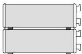
natural_image
Pure diagram of two rectangular electronic components with mounting holes, no text or symbols present
text_image
Diagram of a digital oscilloscope with labeled input/output ports and control knobs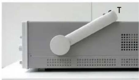
natural_image
Close-up of a white cylindrical device with a handle, labeled 'T' on the side (no other text or symbols visible)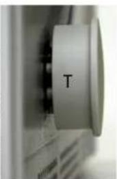
natural_image
Close-up of a computer monitor with a circular button labeled 'T' (no additional text or symbols visible)
General information regarding the CE marking
HAMEG instruments fulfill the regulations of the EMC directive. The conformity test made by HAMEG is based on the actual generic- and product standards. In cases where different limit values are applicable, HAMEG applies the severer standard. For emission the limits for residential, commercial and light industry are applied. Regarding the immunity (susceptibility) the limits for industrial environment have been used.
The measuring- and data lines of the instrument have much influence on emission and immunity and therefore on meeting the acceptance limits. For different applications the lines and/or cables used may be different. For measurement operation the following hints and conditions regarding emission and immunity should be observed:
1. Data cables
For the connection between instrument interfaces and external devices, (computer, printer etc.) sufficiently screened cables must be used. Without a special instruction in the manual for a reduced cable length, the maximum cable length of a dataline must be less than 3 meters and not be used outside buildings. If an interface has several connectors only one connector must have a connection to a cable.
Basically interconnections must have a double screening. For IEEE-bus purposes the double screened cable HZ72 from HAMEG is suitable.
2. Signal cables
Basically test leads for signal interconnection between test point and instrument should be as short as possible. Without instruction in the manual for a shorter length, signal lines must be less than 3 meters and not be used outside buildings.
Signal lines must screened (coaxial cable - RG58/U). A proper ground connection is required. In combination with signal generators double screened cables (RG223/U, RG214/U) must be used.
3. Influence on measuring instruments
Under the presence of strong high frequency electric or magnetic fields, even with careful setup of the measuring equipment, influence of such signals is unavoidable.
This will not cause damage or put the instrument out of operation. Small deviations of the measuring value (reading) exceeding the instruments specifications may result from such conditions in individual cases.
4. RF immunity of oscilloscopes.
4.1 Electromagnetic RF field
The influence of electric and magnetic RF fields may become visible (e.g. RF superimposed), if the field intensity is high. In most cases the coupling into the oscilloscope takes place via the device under test, mains/line supply, test leads, control cables and/or radiation. The device under test as well as the oscilloscope may be effected by such fields.
Although the interior of the oscilloscope is screened by the cabinet, direct radiation can occur via the CRT gap. As the bandwidth of each amplifier stage is higher than the total -3dB bandwidth of the oscilloscope, the influence of RF fields of even higher frequencies may be noticeable.
4.2 Electrical fast transients / electrostatic discharge
Electrical fast transient signals (burst) may be coupled into the oscilloscope directly via the mains/line supply, or indirectly via test leads and/or control cables. Due to the high trigger and input sensitivity of the oscilloscopes, such normally high signals may effect the trigger unit and/or may become visible on the CRT, which is unavoidable. These effects can also be caused by direct or indirect electrostatic discharge.
Declaration of Conformity 24
General information regarding the CE marking 24
HM400 Analog Oscilloscope 40 MHz 26
Specifications 27
Important hints 28
Placement of the instrument 28
Removing/mounting the handle 28
Safety 28
Proper operation 28
CATI 28
Areas of use of the instrument 29
Environmental conditions. 29
Maintenance 29
Warranty and repair 29
Line voltage 29
Overview of the controls 30
Basic signal measurement 31
Nature of the signal voltages 31
Amplitude of signals. 32
Time measurements 32
Applying the signal voltages 32
First time operation and initial settings 33
Trace rotation 33
Probe adjustment and use of probes 33
1 kHz adjustment 33
1 MHz adjustment 33
Operating modes of the vertical amplifier 34
XY mode 34
Measurement of phase differences in dual channel operation 34
Triggering and time base 34
Automatic peak-to-peak triggering 34
Normal trigger 35
SLOPE selection 35
Trigger coupling 35
TV (video signal) triggering (PAL) 35
Frame pulse triggering 35
Line sync triggering 35
LINE triggering 36
External triggering 36
Triggered state indicator LED TRIG'd 36
Hold-off time adjustment 36
AUTOSET 37
Component test 37
In-circuit tests 38
Function of the controls 38
① POWER 38
② ADJUST - / + 38
③ Indication LEDs 38
④ SELECT 38
5 POSITION 1 + POSITION 2 - knobs 38
6 SAVE/RECALL 39
⑦ AUTOSET 39
8 AUTO/NORM -LED button 39
9 SLOPE - LED button 39
10 TRIGGER LEVEL - knob 39
11 TRIG'd - LED 39
12 X-MAG/ x10 - Button with „x 10" LED 39
13 X-POSITION 39
14 VOLTS/DIV - knobs (CH1 / CH2) 39
15 TIME/DIV - knob 39
16 CH 1 - LED button 40
17 CH 2 - LED button 40
18 LINE - LED button 40
19 EXT - LED button 40
20 AC - LED button 40
21 DC - LED button 40
22 LF - LED button 40
23 TV - LED button 40
24 DC/AC - LED buttons (CH 1 / CH 2) 40
25 GND - LED buttons (CH 1 / CH 2) 40
26 INV - LED button for CH 2 40
27 HOLD-OFF/ON - LED button 40
28 Z-INP - LED button 40
29 INPUT CH 1 / CH 2 - BNC connectors 40
30 PROBE ADJUST - Contacts 41
31 EXT.TRIG/Z-INP - BNC connector 41
32 Mode buttons with LED 41
33 COMPONENT TESTER - 41
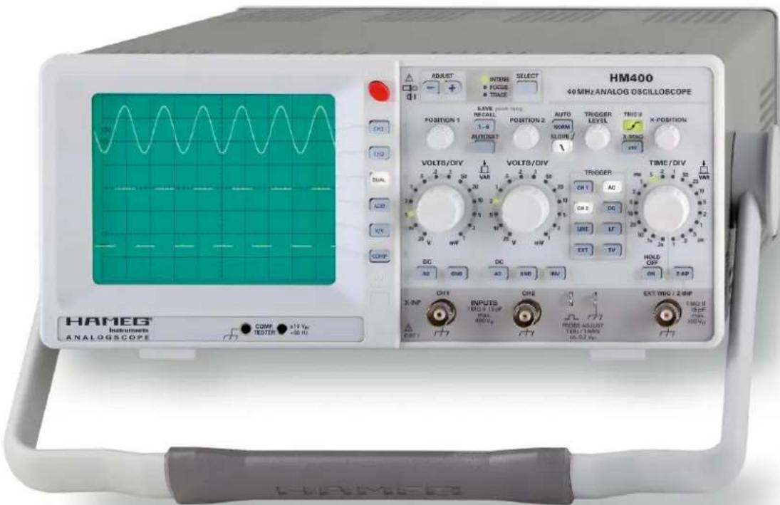
40MHz Analog Oscilloscope
HM400
text_image
HM400 40 MHz ANALOG OSCILLOSCOPE ADJUST INTER FOCUS TRACE SELECT Position 1 SAVE RECALL 1-8 AUTO RORM SLORE TRI0 9 X-POSITION AUTOSST VOLTS/DIV VOLTS/DIV TROGER DR 1 AC CH 2 DC UNIT IF EXT TV TIME/DIV PWR 5 2 1 20 VAR DC DC HOLD OFF OR 2.4P INPUTS YOUT 1 Vp MAX ABOVE CH2 FROM ADJUST 10Hz 10Hz 16.02 Vp EXT THWG / 2.4MP HAMEG Instruments ANALOGSCOPE COPM x14 Vp TESTER x36 VpNo signal distortion resulting from overshoot
natural_image
Green grid background with a white line segment on the right edge (no text or symbols)Line triggered composite video signal

natural_image
Abstract grid pattern with light blue pixelated shapes on teal background (no text or symbols)Characteristic of a Z-Diode with component test mode
natural_image
Green grid background with a white line segment on the right edge (no text or symbols)☑Reference-Class in sensitivity and input voltage range
☑2 Channels with deflection coefficients 1 mV/div....20 V/div., variable up to 50 V/div.
☑Time Base 100 ns/div....0.2 s/div., with X magnification to 10 ns/div.
☑Low noise measuring amplifiers with high pulse fidelity and minimum overshoot
☑ Peak to peak trigger for stable triggering 0...50 MHz at 0.5 div. signal level (up to 80 MHz at 1 div.)
☑Autoset, Save/Recall Memories for 6 instrument settings
☑Yt- and XY-Mode with Z-Input for intensity modulation
☑ Component characterisation with component tester (two terminal network measurement) for use within service etc.
☑Low power consumption, no fan
40MHz Analog Oscilloscope HM400
All data valid at 23 °C after 30 minute warm-up
Vertical Deflection
| Operating Modes: Channel 1 or 2 only |
| Channels 1 and 2 (alternate or chopped) |
| Sum or Difference of CH 1 and CH 2 |
Invert: CH 2
XY Mode: CH 1 (X) and CH 2 (Y)
Bandwidth (-3 dB):
DC, 5mV/div...20V/div.: 0...40MHz
AC, 5mV/div...20V/div.; 2Hz...40MHz
DC, 1...2mV/div.: 0...10MHz
AC, 1...2mV/div.: 2Hz...10MHz
Rise Time (calculated): < 35 ns (1 mV/div....2 mV/div.)
< 8.75 ns (5 mV/div....20 V/div.)
Deflection Coefficient: 1-2-5 Sequence
± 5% [1mV/div....2mV/div.]
± 3% [5mV/div....20V/div.]
Variable (uncalibrated): > 2.5:1 to > 50 V/div.
Input Impedance: 1 MΩ II 15 pF
Input Coupling: DC, AC, GND (ground)
Max. Input Voltage: 400 V (DC + peak AC)
Triggering
| Automatic: | Linking of peakdetection and triggerlevel |
| Min. signal height | 0.5div |
| Frequency range | 5Hz...50MHz |
| Level control range | From peak- to peak+ |
| Normal (without peak): | |
| Min. signal height | 0.5div |
| Frequency range | 0...50MHz |
| Level control range | -10....+10div. |
| Slope: | Rising or falling |
| Sources: | Channel 1 or 2, Line and External |
| Coupling: | AC (5 Hz...80 MHz), DC (0...80 MHz), LF (0...1.5 kHz) |
| Trigger Indicator: | LED |
ernal Trigger:
Input Impedance: 1MΩ II 15pF
External Trigger Signal: 0,3 V _pp ≤ 5 V,
DC (0...50 MHz), AC (20 Hz...50 MHz)
Max. input voltage: 100V (DC + Peak AC)
Active TV sync. separator: Field and Line, +/-
Horizontal Deflection
| Time Base: | 100 ns/div....0.2 s/div (1-2-5 Sequence) |
| Accuracy: | ±3 % |
| Variable (uncalibrated): | >2.5 :1 to >1.25 s/div. |
| X Magnification x 10: | up to 10 ns/div. |
| Accuracy: | ±5 % |
| Hold-Off Time: | variable to approx. 10 : 1 |
| XY | |
| Bandwidth X amplifier: 0...2.5 MHz (-3 dB) | |
| XY Phase shift < 3°: | < 120 kHz |
Operation/Readout/Control
| Manual: | via controls and buttons |
| Autoset: | automatic signal related parameter settings |
| Save and Recall: | 6 instrument parameter settings |
Component Tester
Test Voltage: approx. 7 Vms (open circuit)
Test Current: max. 7 mA _rms (short-circuit)
Test Frequency: approx. 50 Hz
| Test Connection: | 2 banana jacks 4mm ∅One test circuit lead is grounded via protective earth (PE) |
Miscellaneous
| CRT: | D14-363GY, 8 x 10 div. with internal graticule |
| Acceleration Voltage: | approx. 2kV |
| Trace Rotation: | adjustable on front panel |
| Z-Input (Intens. modulation): | max. +5 V (TTL), 10 kHz |
| Probe ADJ Output: | 1 kHz/1 MHz Square Wave Signal ca. 0.2 V_p (tr < 5 ns) for probe adjustment |
| Power Supply (Mains): | 105...253V, 50/60Hz ± 10%, CAT II |
| Power Consumption: | approx. 30 Watt at 230V/50 Hz |
| Safety class: | +5 °C...+40 °CN61010-1] |
| Operating temperature: | +5...+40°C |
| Storage temperature: | -20...+70°C |
| Rel. humidity: | 5...80% (non condensing) |
| Dimensions (W x H x D): | 285 x 125 x 380mm |
| Weight: | approx. 4.8kg |
Accessories supplied: Line Cord, Operators Manual, 2 Probes 1:1/10:1 (HZ154) with LF/HF adjustment
Optionales Zubehör:
| HZ20 | Adapter, BNC to 4mm banana |
| HZ33 | Test cable 50Ω, BNC/BNC, 0.5m |
| HZ34 | Test cable 50Ω, BNC/BNC, 1m |
| HZ45 | 19"-Rackmount Kit 4RU |
| HZ51 | Probe 10:1 [150MHz] |
| HZ52 | Probe 10:1 RF (250MHz) |
| HZ53 | Probe 100:1 [100MHz] |
| HZ56-2 | AC/DC Current probe |
| HZ100 | Differential probe 20:1 / 200:1 |
| HZ109 | Differential probe 1:1 / 10:1 |
| HZ115 | Differential probe 100:1 / 1000:1 |
| HZ200 | Probe 10:1 with auto attenuation ID (250MHz) |
| HZ350 | Probe 10:1 with automatically identification (350MHz) |
| HZ355 | Slimline probe 10:1 with automatically identification (500MHz) |
| HZ020 | High voltage probe 1000:1 (400MHz,1000Vrms) |
| HZ030 | Active probe 1GHz (0.9pF, 1MΩ, including many accessories |
| HZ050 | AC/DC Current probe 20A, DC...100kHz |
| HZ051 | AC/DC Current probe 1000A, DC...20kHz |
www.hameg.com
HM400E/091109/ce · Subject to changes · © HAMEG Instruments GmbH® · DQS-certified in accordance with DIN EN ISO 9001:2000, Reg.-No.: DE-071040 QM HAMEG Instruments GmbH · Industriestr. 6 · D-63533 Mainhausen · Tel +49 (0) 6182 800 0 · Fax +49 (0) 6182 800 100 · www.hameg.com · info@hameg.com
Important hints
Immediately after unpacking check the instrument for any mechanical damage and loose parts inside. In case of transport damage inform the supplier. Do not operate the instrument.
Symbols

Consult
the

observe this note
Ground, earth
Placement of the instrument
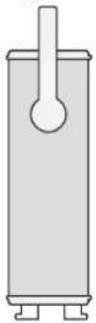
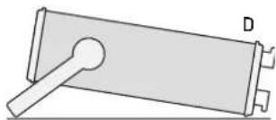
The pictures show how to move the handle into various positions.
A: Carrying position
B: Position for horizontal carrying resp. for removing the handle
C: Horizontal operating position
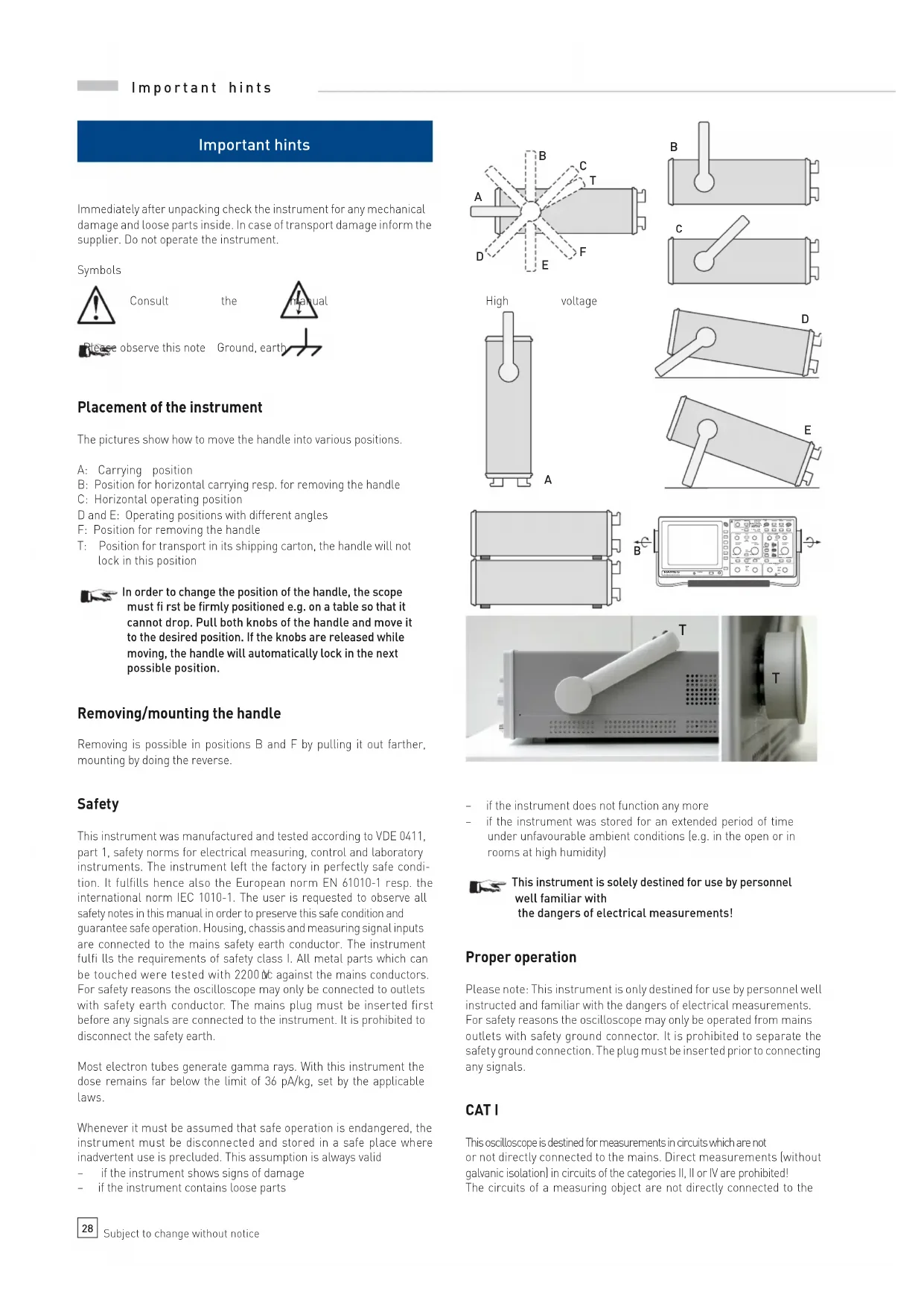
D and E: Operating positions with different angles
F: Position for removing the handle
T: Position for transport in its shipping carton, the handle will not lock in this position

In order to change the position of the handle, the scope must fi rst be firmly positioned e.g. on a table so that it cannot drop. Pull both knobs of the handle and move it to the desired position. If the knobs are released while moving, the handle will automatically lock in the next possible position.
Removing/mounting the handle
Removing is possible in positions B and F by pulling it out farther, mounting by doing the reverse.
Safety
This instrument was manufactured and tested according to VDE 0411, part 1, safety norms for electrical measuring, control and laboratory instruments. The instrument left the factory in perfectly safe condition. It fulfills hence also the European norm EN 61010-1 resp. the international norm IEC 1010-1. The user is requested to observe all safety notes in this manual in order to preserve this safe condition and guarantee safe operation. Housing, chassis and measuring signal inputs are connected to the mains safety earth conductor. The instrument fulfi lls the requirements of safety class I. All metal parts which can be touched were tested with 2200 NC against the mains conductors. For safety reasons the oscilloscope may only be connected to outlets with safety earth conductor. The mains plug must be inserted first before any signals are connected to the instrument. It is prohibited to disconnect the safety earth.
Most electron tubes generate gamma rays. With this instrument the dose remains far below the limit of 36 pA/kg, set by the applicable laws.
Whenever it must be assumed that safe operation is endangered, the instrument must be disconnected and stored in a safe place where inadvertent use is precluded. This assumption is always valid
- if the instrument shows signs of damage
- if the instrument contains loose parts

text_image
A B C T D E F
natural_image
Simple line drawing of a cylindrical object with a label B, no text or symbols presentHigh
voltage

natural_image
Pure mechanical diagram of a lever and plate assembly without any text or symbols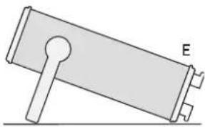
natural_image
Simple line drawing of a mechanical component with labeled point E (no text or symbols beyond label)
natural_image
Pure diagram of two stacked rectangular blocks with no text, numbers, or symbols
text_image
B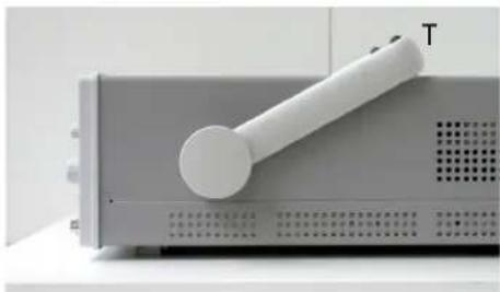
natural_image
Close-up of a white electronic device with a handle and label 'T' on its side, mounted on a gray base (no visible text or symbols beyond the label)
natural_image
Close-up of a computer monitor with a circular button labeled 'T' (no additional text or symbols visible)- if the instrument does not function any more
- if the instrument was stored for an extended period of time under unfavourable ambient conditions (e.g. in the open or in rooms at high humidity)

This instrument is solely destined for use by personnel well familiar with the dangers of electrical measurements!
Proper operation
Please note: This instrument is only destined for use by personnel well instructed and familiar with the dangers of electrical measurements. For safety reasons the oscilloscope may only be operated from mains outlets with safety ground connector. It is prohibited to separate the safety ground connection. The plug must be inserted prior to connecting any signals.
CAT I
This oscilloscope is destined for measurements in circuits which are not or not directly connected to the mains. Direct measurements (without galvanic isolation) in circuits of the categories II, II or IV are prohibited! The circuits of a measuring object are not directly connected to the
mains if the measuring object is operated via an isolation transformer of safety class II. Indirect measurements on the mains are also possible with special probes, e.g. current probes, which fulfil II the requirements of the safety class II. With such measurements the measurement category specified by the manufacturer for the probe has to be observed.
Measurement categories
The measurement categories relate to transients on the mains. Such transients are short but very fast (short rise time) voltage or current excursions which may be periodic or not. The amplitude of possible transients increases the shorter the distance to the source of the mains installation is.
Measurement category IV: Measurements directly at the source of the mains installation, e.g. at the electricity meters.
Measurement category III: Measurements within the mains installations, e.g. at distribution points, power switches, wall outlets, permanently mounted motors etc.
Measurement category II: Measurements at circuits which are directly connected to the mains, e.g. household appliances, portable tools etc.
Measurement category I: Electronic apparatus and fused circuits within such apparatus.
Areas of use of the instrument
The oscilloscope is destined for use in the following areas: industrial, housing, business, workshops.
Environmental conditions.
The permissible operating temperature range is +5 to +40 °C. During storage or transport the temperature range is -20 to +70 °C. Condensation of water during transport or storage requires a 2 hour drying period before operation. The oscilloscope is destined for use in dry, clean rooms. It must not be operated if there is severe dust or if the humidity is excessive nor if there is danger of explosion or aggressive chemical reaction.
The orientation during operation may be any. Suffi cient air circulation has to be provided, however. Continuous operation requires a horizontal or tilted (handle) position.

Do not cover the ventilation holes!
All nominal specifications and tolerances are valid after a warm-up time of at least 30 min. and at an ambient temperature of +23 degr. C. Specifications without a tolerance given are those of a typical instrument.
Maintenance
Clean the outside of the housing regularly with a brush. Dirt on the housing, the handle, plastic, and aluminum parts may be removed with a cloth and a mild detergent (1%). Dirt containing fat may be removed with alcohol or petrol ether. The screen may be only cleaned with water or benzine, but not with alcohol or solvents, after cleaning it should be wiped with a dry clean cloth. After cleaning it should be treated with a customary antistatic solution for plastics. Under no circumstances any cleaning fluid should enter the instrument. Use of any other cleaning agent may damage the plastic and lacquered surfaces.
Warranty and repair
HAMEG instruments are subjected to a strict quality control. Prior to leaving the factory, each instrument is burnt-in for 10 hours. By intermittent operation during this period almost all defects are detected.
Following the burn-in, each instrument is tested for function and quality, the specifications are checked in all operating modes; the test gear is calibrated to national standards.
The warranty standards applicable are those of the country in which the instrument was sold. Reclamations should be directed to the dealer.
Only valid in EU countries
In order to speed reclamations customers in EU countries may also contact HAMEG directly. Also, after the warranty expired, the HAMEG service will be at your disposal for any repairs.
Return material authorization (RMA):
Prior to returning an instrument to HAMEG ask for a RMA number either by internet (http://www.hameg.com) or fax. If you do not have an original shipping carton, you may obtain one by calling the HAMEG service dept (phone: +49 [0] 6182 800 500, fax: +49 [0] 6182 800 501) or by sending an e-mail to service@hameg.com.
Line voltage
The instrument may be operated with any voltage between 105 V to 253 V, 50/60 Hz, hence there is no line voltage selector.
The line fuses is accessible from the outside. The mains connector and the fuse holder are one unit. The fuses can only be exchanged (if the fuse holder was not damaged) after the mains cable has been detached. In order to remove the fuses, use a small screw driver (appr. 2 mm) and push it into the two slanted slots at both sides of the fuse holder, this will release it, it will pop out by spring force. The fuses may then be exchanged. Please take care not to bend the contact springs. Inserting the fuse holder requires that the protruding notch points to the mains connector. The fuse holder has to be pushed in against the spring force until both latches catch it. It is prohibited to use „repaired“ fuses or to short -circuit the fuse. Any damages incurred by such manipulations will void the warranty.
Type of fuse
Size 5 x 20 mm
250 V AC, C
IEC 127, p. III, DIN 41 662 (also DIN 41 571, p. 3)
Slow blow T 0.8 A.

Overview of the controls
① POWER (button): Mains on/off 36
② ADJUST - / + (buttons) 36
Allows to change diverse settings depending on the selection with the button SELECT ④
3 Indicator LEDs 36
INTENS: The LED will light up if intensity adjustment was selected with the button SELECT 4
FOCUS: The LED will light up if focus adjustment was selected with the button SELECT 4
TRACE: The LED will light up if trace rotation adjustment was selected with the button SELECT 4
4 SELECT (button) 37
Allows to change some settings relating to the crt like intensity,
focus, trace rotation by pressing the buttons ADJUST ② when
the respective LED lights up.
5 POSITION 1 + POSITION 2 |knobs| 37
Changes the trace position of channel 1 or channel 2 resp..
⑥ SAVE / RECALL [LED button] 37
In conjunction with any of the mode buttons ③2 this button allows to address the settings memories
⑦ AUTOSET (button) 37
Automatically selects a reasonable instrument setting for most signals
8 AUTO / NORM (LED button) 37 Selects either automatic (AUTO) or normal (NORM) triggering. The LED will light up if normal triggering was selected, otherwise automatic triggering is enabled.
⑨ SLOPE (LED button) 37 Selects either the positive or the negative signal slope. The LED will light up if the negative slope was selected.
10 TRIGGER LEVEL (knob) 37
Changes the trigger level of the time base.
11 TRIG'd (LED)
The LED will light up if the instrument receives a valid trigger signal and operates in triggered mode
37
12 X-MAG/x 10 (LED button) 37
If the x 10 magnifier is enabled, the display will be expanded in X direction around the screen center ten times with a corresponding change of the time base speed. The LED will light up if the magnifier is active.
13 X-POSITION (knob) 37
Changes the X position of the trace(s)
14 VOLTS/DIV; CH1 + CH2 (knobs) 37
Channel 1 or channel 2 sensitivity selection. By pressing the corresponding knob, the variable will be activated, and, as long as it is activated, the display of the sensitivity will blink, because the sensitivity is uncalibrated.
15 TIME/DIV (knob) 37 Selects the time base speed. By pressing the knob, the variable will be activated, and, as long as it is activated, the display of the time base speed will blink, because the time base speed is uncalibrated. This knob also has a third function: hold-off time adjustment, see 27.
16 CH 1 (LED button) 38 Selects channel 1 as the trigger source as indicated by the LED.
17 CH 2 (LED button) 38 Selects channel 2 as the trigger source as indicated by the LED.

text_image
ADJUST - + INTENS FOCUS TRACE SELECT 32 1 5 6 7 5 8 9 10 11 12 13 POWER ADJUST - + INTENS FOCUS TRACE SELECT 40MHz ANALOG OSCILLOSCOPE POSITION 1 SAVE RECALL 1-8 AUTOSET POSITION 2 AUTO NORM SLOPE/ TRIGGER LEVEL TRIG'd X-MAG x10 X-POSITION VOLTS/DIV VAR VOLTS/DIV TRIGGER CH 1 AC CH 2 DC LINE LF EXT TV TIME/DIV ms 5.2.1 ms 20 VAR AC GND DC AC GND INV HOLD OFF ON Z-INP X-INPUT CH 1 INPUTS 1 MHz 15pF max. 400 Vp CH2 PROBE ADJUST 1kHz / 1MHz ca. 0.2 Vpp EXT TRIG / Z-INP CAT I CATI 14 24 29 14 24 29 26 30 27 31 28 COMP TESTER ±10 Vpp -50 Hz 33 15 16 17 18 19 23 22 21 20 TRIGGER CH 1 AC CH 2 DC LINE LF EXT TV18 LINE (LED button) 38
Selects the mains as the trigger source as indicated by the LED.
19 EXT (LED button) 38
Selects the external input as the trigger source as indicated by the LED.
20 AC [LED button] 38
Selects AC coupling for the trigger source as indicated by the LED.
21 DC (LED button) 38
Selects DC coupling for the trigger source as indicated by the LED.
22 LF (LED button) 38
Switches a low pass filler into the trigger channel as indicated by the LED
23 TV (LED button) 38
Selects TV signal triggering as indicated by the LED.
24 DC/AC; CH1 + CH2 (LED buttons) 38
Selects DC or AC coupling for channel 1 or channel 2 resp.. If AC is selected, the LED will light up.
25 GND; CH1 + CH2 (LED buttons) 38
Disconnects the input of channel 1 or channel 2 resp. and connects it to ground internally as indicated by the LED.
26 INV (LED button) 38
Inverts the signal of channel 2 (CH 2) as indicated by the LED. (Inversion of channel 1 is not available.)
27 HOLD OFF/ON(LED button) 38
By pressing this button a hold-off time can be selected, the amount of hold-off can be adjusted with the knob TIME/DIV. 15.
28 Z-INP (LED button)
Activates the external Z axis input as indicated by the LED. 31 for intensity modulation
29 INPUT CH 1 + CH 2 (BNC connectors)
Signal input for channel 1 or channel 2 resp.. In XY mode the CH1 input will control the horizontal movement (X) of the trace.
30 PROBE ADJUST ∩ (contact)
1 KHz/1 MHz square wave output for the adjustment of probes other than 1:1.
PROBE ADJUST (contact)
Ground connection for the probe adjustment.
31 EXT. TRIG/Z-INP (BNC connector)
Input for external trigger or intensity modulation signals.
32 Mode select buttons with LED:
CH 1: Activates the channel 1 | CH 1| input or selects access to the settings memory 1 as indicated by the LED.
CH 2: Activates the channel 2 (CH 2) input or selects access to the settings memory 2 as indicated by the LED.
DUAL: Selects dual channel operation or access to the settings memory 3 as indicated by the LED.
ADD: Selects the add mode of the vertical amplifier or access to the settings memory 4 as indicated by the LED.
XY: Selects the XY mode or access to the settings memory 5 as indicated by the LED.
COMP: Activates the COMPONENT tester or selects access to the settings memory 6 as indicated by the LED.
33 COMPONENT TESTER (two 4 mm test jacks)
39
Terminals of the component tester, the left one is connected to the chassis and thus to the safety earth connector of the mains cable.
Basic signal measurement
Nature of the signal voltages
The oscilloscope HM400 displays in real time most repetitive signals containing frequencies from DC to beyond 40 MHz (-3 dB). The vertical amplifier is designed for minimum overshoot.
The display of simple electrical waveforms like LF or HF sine waves or mains frequency ripple is no problem. When measuring the amplitude of sine waves, the frequency response of the oscilloscope has to be taken into account which begins to fall off at fairly low frequencies. At 25 MHz the amplitude error will amount to appr. -10 %. Due to the tolerance of the -3 dB frequency the exact amount of the amplitude error may vary.
Square wave or pulse signals, in general all nonsinusoidal signals, contain frequencies well above their repetition frequency, depending on their shape and rise resp. fall times. This oscilloscope has a rise time of 8.5 ns and will reproduce signals fairly well if their rise times remain 3 to 5 times slower. It follows that the repetition rate of such nonsinusoidal signals must remain considerably lower than the -3 dB frequency of 40 MHz, otherwise their harmonics will be attenuated too much, i.e. the edges will be rounded.
It is more difficult to display socialled mixed signals unless there is a repetition frequency with outstanding amplitudes, so the scope can trigger on them. This may be the case with burst signals. In order to obtain a stable display, it may be necessary to vary the hold-off time. The active TV sync separator will allow stable triggering on video signals.
The fastest time base speed using the magnifier is 10 ns/div which allows to spread a period of 40 MHz over 2.5 divisions, consequently, time resolution is no problem.
The vertical amplifier is DC coupled, when AC coupling is selected, a capacitor is switched in series with the signal input. The normal coupling mode is DC; if the DC content of the input signal is too high, AC coupling will be required. In this case, however, two effects need to be considered. Signals with a very low frequency content may be distorted, e.g. low frequency square waves will show tilt (appr. 1.6 Hz – 3 dB). Signals with varying duty cycle will be displayed with a vertical shift depending on the duty cycle corresponding to their DC content. The low frequency limit could be reduced by selecting DC coupling and connecting an external larger capacitor of sufficient voltage rating, but use of this method is discouraged, a 10:1 probe will reduce the low frequency -3 dB point to 0.16 Hz. Due to their internal circuit, 100:1 and 1000:1 probes do not reduce the lower frequency -3 dB frequency. As outlined in more detail later, oscilloscopes are rarely used without probes.
Amplitude of signals.
In electrical engineering, ac voltages are given in rms units. Oscilloscopes show the actual peak-to-peak voltages, hence they are calibrated in V_pp . In order to arrive at the RMS value of a sine wave, its pp - value must be divided by 2.83. RMS voltages will be displayed larger by that factor.
The highest sensitivity of this scope is 1 mV/DIV, a signal of 1 division will amount to 1 mVpp ±5% unless the variable is activated. Calibrated measurements require that the "variable" is off. The variable allows to decrease the sensitivity by a factor of appr. 2.5 to a lowest of appr. 50 V/DIV. The variable also allows to bridge the 1 – 2 – 5 steps of the input attenuators. Without a probe signals of up to 400 V p may be displayed (50 V/DIV x 8 divisions). In order to measure the amplitude of a signal, it is only necessary to read the height of the display and multiply it by the sensitivity selected in V/DIV.

Without a probe the maximum input voltage at both inputs is + or - 400 Vp.
In case the signal consists of DC and AC, the DC plus peak AC must not exceed + or - 400 V p . A pure ac voltage may reach 800 V pp (of which only 400 Vpp can be displayed on the screen.)

If 10:1 probes are used, their possibly higher maximum voltages may only be made use of if the scope input is switched to DC coupling. This does not apply to 100:1 or 1000:1 probes.
Considering the foregoing, HAMEG HZ154 10:1 probes allow to measure DC up to 400 V and pure ac voltages up to 800 V, and HAMEG HZ53 100:1 probes dc voltages up to 1200 V and pure ac voltages up to 2400 V. Please observe the decrease of the permissible input voltage with increasing frequency for each probe type, see the respective probe manuals. Risking the measurement of excessive voltages with a standard 10:1 probe may cause a short of the probe's input capacitor which could destroy the scope input circuitry!
It is possible to measure the ripple on a high voltage by inserting a high voltage capacitor in series with a 10:1 probe, but it is mandatory to switch the input to DC; in order to avoid excessive transients, the input must first be switched to ground, then the high voltage applied, then the input switched to DC. The high voltage capacitor has to be discharged with proper care using a resistor of sufficient voltage rating!
The GND position of the input coupling selector is used to set the base line using the POSITION control as desired before switching to DC.
Time measurements
As a rule, scopes are used to display repetitive signals, the designation period is used here for simplicity. The repetition frequency is equal to the number of periods per second. Depending on the setting of the TIME/DIV switch one or more periods may be displayed or just portions of one period. The time base speeds are indicated by the LEDs around the circumference of the TIME/DIV knob in us/DIV, ms/DIV, s/DIV.
In order to measure the period or portions of a signal, read the number of divisions and multiply this by the time base speed selected.
The HORIZONTAL position knob allows to shift the horizontal position of the trace. Rise and fall times are defined between 10 and 90 % of the full amplitude.
Applying the signal voltages
Use AUTOSET for a quick automatic selection of suitable display parameters (see AUTOSET). The following paragraph applies to manual operation. The function of the controls is detailed in the chapter „Controls”.

Be careful when applying unknown signals to the vertical amplifier.
Without a probe set the VOLTS/DIV switch to 20 V/DIV and use AC coupling. If the trace disappears after application of the signal, it is possible that the signal amplitude is much too large and overdrives the vertical amplifier. Decrease the sensitivity (increase the VOLTS/DIV setting) until the signal remains fully within the screen area. If portions of the signal fall outside this area, they may still overdrive the amplifier which can cause distortions! With calibrated 20 V/DIV a probe will be required if the signal exceeds 160 Vpp, if the variable is activated up to 400 Vpp may be displayed without a probe. The probe used must be specified for the maximum voltage applied.
Please note that the display of signals with a low repetition rate at high sweep speeds will cause the trace to dim, the intensity may be increased until the trace starts to blur. In such case the time base speed must be decreased so far that the trace remains visible.
The signals may be connected to the scope either through shielded cables or by using probes. The use of cables is restricted to low frequencies and low impedance signal sources because they add typically 100 pF/m load capacitance. At higher frequencies cables with standard characteristic impedances like 50 Ω can be used if they are correctly terminated at both ends. HAMEG HZ22 feedthrough terminations at the scope can be used together with HAMEG 50 Ω cables such as HZ34. Incorrect or missing terminations will cause massive pulse distortions. Generators, amplifiers etc. will only perform to specifications if they are feeding properly terminated cables. The HZ22 is specified for a maximum of 2 W which is reached if the signal increases to 10 V rms or 28.3 V pp .
With probes no terminations are needed nor allowed, the probes are directly connected to the scope's BNC connectors. Probes load high impedance sources only moderately (10:1 probes with 10 MΩ II 12 pF, 100:1 with 10 MΩ//5 pF), but this applies only up to appr. 100 KHz, above the loading increases with increasing frequency, see the probe manuals for details, also for the necessary derating. Passive probes are unsuited for measurements on high Q HF circuits!
As mentioned, in most applications probes are used, at least as long as the loss in sensitivity can be compensated by increasing the scope's sensitivity. Also, a probe offers protection for the scope's input circuit. Because probes are manufactured separated from the scopes, they are only coarsely preadjusted, it is absolutely necessary to adjust each probe to the input it is used on [see Probe Adjustment].
Probes may decrease the bandwidth of a scope considerably if they are the wrong type! We recommend to use the HAMEG HZ51 (10:1), HZ52 (10:1 HF), HZ154 (1:1 and 10:1) probes. Replacement parts may be ordered from HAMEG and may be exchanged by the user. The probes mentioned have a HF adjustment in addition to the basic 1 KHz adjustment. By using the 1 MHz probe adjust signal, the HF adjustment corrects for group delay aberrations near the -3 dB frequency. With these probes the HM400 rise time/bandwidth remain nearly constant. The probe HF adjustment also allows for an optimum pulse response of the combination probe and scope.

With a 10:1 or 100:1 probe DC coupling has to be used if the signal voltage exceeds 400 Vp.
As mentioned if AC coupling is used, the 1.6 Hz–3 dB frequency comes into play which causes distortions with low frequency signals, e.g. square waves are displayed with tilt. With a 10:1 probe the low frequency response is improved by a factor of ten (0.16 Hz). If the sensitivity with this probe is insufficient, DC coupling and an external capacitor can be used e.g. for ripple superimposed on a high dc potential. First the input must be switched to GND, then the voltage applied, then the input switched to DC.
The measurement of small voltages requires proper ground connections as close to the measuring point as possible. Use short ground cables.

If a probe is to be used to contact a BNC connecto, a probe to BNC adapter should be used in order to prevent grounding problems.
If ripple or noise appears on small signals at high sensitivity settings, multiple grounds resp. ground loops may cause the problem. The mains safety earth is quite often the cause, because other test equipment will also be connected to the same safety earth, this can generate currents through the shields of cables etc. Most instruments have so-called Y capacitors connected from the mains to safety earth.
First time operation and initial settings
Prior to any use of the instrument make sure the power plug is inserted before any other contacts are established.
Turn the instrument on by pressing the red button POWER, seven indicators will light up, the oscilloscope will perform a self-test. If any errors are detected, there will be 5 acoustic signals; it is recommended to submit the instrument to a service station. After a successful self-test the instrument will be ready to operate, it will use the settings stored from its last use.
If there is no trace after a 20 s wait, press the AUTOSET button. If the trace is now visible, use the SELECT button, the ADJUST +/− buttons to set the desired intensity and optimum focus. For best focus adjustment it is recommended to display a full screen sine wave. If no input signal is connected, switch the input to GND in order to prevent any noise from disturbing the focus adjustment.
In order to extend the life of the crt, set the intensity no higher than needed for the specific measurement under the given ambient light conditions. Take care not to leave a bright spot as this could burn the crt phosphor. Do not turn the instrument on and off in short intervals.
It is recommended to always use first the button AUTOSET and select the buttons AC and CH 1 in the TRIGGER select area.
Trace rotation
In spite of the mumetal crt shield the earth's magnetic fi eld still has some influence on the crt beam. Depending on the orientation of the instrument the trace may not always remain parallel to the graticule lines. See the chapter Controls for the adjustment of the trace rotation.
Probe adjustment and use of probes.
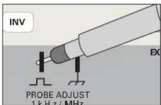
Probes have to be adjusted to the input they are connected to; this adjustment has to be performed each time a probe is moved to another input. A generator in the HM400 delivers a fast rise time (<5 ns) square wave signal of appr. 0.2 Vpp the frequency of which can be selected by using the knob TIME/DIV (see the chapter Controls). The square wave signal is accessible at the two contacts below the controls. The 0.2 V pp are destined for 10:1 probes, sufficient for 4 divisions at 5 mV/DIV.
text_image
INV EX PROBE ADJUST 1 kHz / MHz1 kHz adjustment
This basic adjustment compensates for the input impedance of the scope, the probe's capacitor is adjusted so that the capacitive division equals the resistive division, the division will thus be identical from DC
to high frequencies. With 1:1 probes or probes which can be switched to 1:1, an adjustment is neither necessary nor possible. Before this adjustment make sure the trace rotation adjustment was performed [see TRACE rotation].
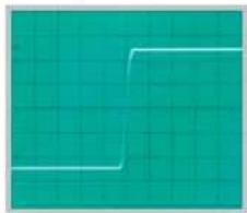
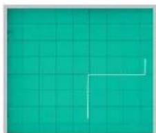
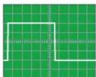
Connect the 10:1 probe to the input, e.g. CH 1, do not press any button, set the coupling to DC, the sensitivity with VOLTS/DIV to 5 mV/DIV, the TIME/DIV switch to 0.2 ms/DIV; make share that both are calibrated, i.e. the variables disabled. Connect the probe tip (and ground cable) to the contact(s). "PROBE ADJUST" [see the photo]; a 4 DIV display of two signal periods should appear. Now adjust the probe capacitor (see the probe manual for its location) until the square wave is perfectly flat, i.e. there are neither under- nor overshoots. The transitions are invisible at this sweep speed (see the pictures). The amplitude of the square wave should be within 4 ±0.12 DIV.
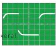
undershoot
correct
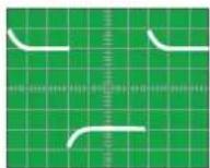
overshoot
1 MHz adjustment
The probes supplied with the scope have additional adjustment elements which allow to correct for aberrations at high frequencies.
After this adjustment maximum bandwidth and best pulse response of the combination scope and probe are obtained by achieving maximally flat group delay; overshoots, undershoots, ripple are minimized.
This adjustment requires a fast square wave generator (< 5 ns) and low output impedance (50 ohms) which delivers 0.2 Vpp at 1 MHz; the PROBE ADJUST output of the scope fulfi lls these requirements.
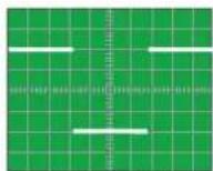
Connect the 10:1 probe to the input to be used. Select PROBE ADJUST signal 1 MHz with the knob „TIME/DIV (see the chapter Controls) switch the coupling to DC, the VOLTS/DIV selector to 5 mV/DIV and the TIME/DIV selector to 100 ns/DIV. Connect the probe Lip and ground to the two PROBE ADJUST contacts. The square wave will now be visible and also its rising and falling slopes. See the probe manual for the location of the adjustment elements.
Adjustment criteria:
Only the rising slope and the top of the square wave are of concern, disregard the other portions of the signal.
- Short rise lime
- Clean transition from the rising slope to the top of the square wave with no over- or undershoot, fl at top.

undershoot
correct

overshoot
The amplitude of the square wave should be identical to that with the 1 kHz signal. It is important to always first perform the 1 kHz adjustment, in general a readjustment of the 1 kHz will not be necessary. Please note that the probe adjust frequencies are not precise and hence must not be used for any checks of the accuracy of the time base, also their duty cycle is not controlled.
The probe adjust signal must conform to the requirements of zero potential at the bottom of the square wave, precise amplitude and fl at tops; its frequencies and duty cycles need not be precise.
Operating modes of the vertical amplifier
The most important controls determining the operating modes of the vertical amplifier are the mode buttons CH 1, CH 2, DUAL, ADD XY 32.
Changing the modes is described in the chapter Controls. Yt is by far the mode most used: the input signal deflects the trace vertically while a time base moves the trace from left to right. The Y amplifier offers these modes:
- Single channel operation of CH 1.
- Single channel operation of CH 2.
- DUAL trace two channel operation.
- Algebraic addition of CH 1 + CH 2 and subtraction of CH 1 - CH 2.
In DUAL trace mode both channels are operating, the time base determines the exact mode of representation, see the chapter Controls. Switching of the channels may either happen alternately after the completion of each time base cycle, or the switching occurs at a high rate during the course of a time base cycle (chopped). The alternating mode is unsuited at slow time bases because the alternation becomes visible with disturbing flicker, here, the chopped mode will yield a flicker-free display. At high sweep speeds the chopped mode is unsuited because the switching transients are disturbing.
In the ADD mode the signals of both channels are algebraically added (CH 1 + CH 2) or subtracted (CH 1 - CH 2) if CH 2 is inverted. If the signals of CH 1 and CH 2 happen to be of opposite phase they may fully or partly cancel, of course.
It is important to bear in mind that the two inputs of the scope are not to be mistaken as the inputs of a true difference amplifier! When using this feature to measure the difference signal between two measuring points, restrictions must be observed: both input attenuators must be switched to the same setting, the common mode rejection is very moderate, and the common mode range is limited to the normal operating range of the input amplifiers. This means in practice that, before the ADD mode is entered, it has to be checked whether each input signal can be displayed, i.e. that is in within the normal operating range; if that is the case for both signals, switch to ADD. Please note further that both POSITION controls affect the vertical position of the added signals. If probes are used, their tolerances will also diminish the common mode rejection; this can be checked by connecting both probes to the same measuring signal, the resulting display should be zero. It is preferable to use the probe adjust or a pulse generator for this test.
XY mode
For this mode use the button XY as described in the chapter Controls under 32.
In this mode the time base is disabled. The CH1 input signal will deflect the trace horizontally, the CH 2 input signal vertically. The horizontal position is controlled as usual with the X-POSITION control. ^13 , the CH 1 position control is disabled. The magnifi er is also disabled. When using this mode, the low bandwidth of the X amplifier (see the specifications) has to be observed, the phase difference between the wide band vertical amplifi er and the X amplifi er increases with frequency.

The Y signal may be inverted by pressing the button INV CH 2.
Using Lissajous patterns it is possible
- to compare two signals of different frequency and to adjust one to the frequency of the other until both are synchronized. This applies also to multiples or fractions of one of the frequencies
- to measure the phase difference between two signals of the same frequency.
Measurement of phase differences in dual channel operation
A much more precise and convenient method of measuring phase differences which is also applicable up to high frequencies is the measurement of the time difference in dual channel operation. Please note: It is mandatory that the trigger signal is taken from only one signal. The phase difference can be easily calculated as the frequency
is known. Another advantage of this method is the fact that the time difference is still measurable even if the signals are corrupted by hum, ripple or noise. Also, there are no ambiguities. Alternatively Lissajous patterns can be used for measurement of phase differences.
$$ \sin \varphi = \frac {a}{b} $$
$$ \cos \varphi = \sqrt {1 - \left(\frac {a}{b}\right) ^ {2}} $$
$$ \varphi = \operatorname{arc} \sin \frac {a}{b} $$
Triggering and time base
The pertinent controls are located to the right of the VOLTS/DIV knobs, see the chapter Controls.
In Yt operation the signal deflects the trace vertically while it is deflected horizontally with constant selectable velocity from left to right. The time base is started by a socalled trigger signal which is derived from any of the available sources. The time base performs one cycle and rests waiting for the next trigger. It is hence immaterial when the next signal arrives, the signal needs only to be repetitive, it need not be periodic! The time between triggers may be any, at low repetition frequencies the display becomes darker, at very low ones the trace will not be visible any more. In order to achieve a stable display, the trigger must always be derived from the very same portion of the signal. The slope and the level of the triggering signal can be chosen.
Note: Various trigger sources are available: the two input channels, an external input, a signal taken from the mains, a TV trigger. Of course, the triggering signal must be synchronous to the signal to be displayed. The minimum amplitude for stable triggering is called the trigger threshold. With internal triggering the trigger signal is taken off in the two input amplifiers, the minimum amplitude here is given in mm vertical deflection, independent of the positions of the VOLTS/DIV switches.
With external triggering the minimum amplitude is given in Vpp at the external trigger input connector. The trigger amplitude may be much larger than the threshold, but it is advisable not to exceed 20 times the threshold.
The oscilloscope features two trigger operation modes to be described.
Automatic peak-to-peak triggering
Please refer to the chapter Controls for specific information about the controls SLOPE 9, TRIGGER-LEVEL 10, and TRIGGER 16 to 23.
When using AUTOSET, this trigger mode will be automatically selected. If DC coupling is selected, the peak-to-peak detection will be disabled, while the function of the auto trigger will remain active. With auto trigger selected, there will be always a trace visible, because the time base will restart periodically if no trigger signal is present or if only a DC voltage is applied. The auto trigger function implies that the user is only required to operate the VOLTS/DIV and TIME/DIV controls.
The TRIGGER-LEVEL knob is active with auto peak-to-peak triggering, its range is automatically adjusted to the peak-to-peak level measured,
it becomes hence independent of the amplitude and the shape of the signal. The duty cycle may e.g. vary from 1:1 to 1:100 without loss of the trigger. It may, however, be sometimes necessary to set the TRIGGER-LEVEL control close to one of its extremes. The next measurement may require another setting. The simplicity of operation recommends the auto peak-to-peak triggering for most uncomplicated measurements. It is also a good start with difficult problems, especially, if the properties of a signal like amplitude, frequency and shape are unknown.
The auto peak-to-peak trigger mode is independent of the trigger source and operates above 5 Hz, i.e., if the repetition frequency of the triggering signal is lower, the time base will freerun.
Normal trigger
In this mode all settings are up to the user, and there is no visible trace if there is no sufficient trigger signal. See the chapter Controls for specific information about the functions of the controls SLOPE 9 , TRIGGER-LEVEL 10 , and TRIGGER 16 to 23 . Complex signals may require the additional use of the functions Time Base Variable (VAR) and HOLD-OFF time adjustment.

In the normal trigger mode the trigger signal can be derived from any portion of the rising or falling slopes of the signal by proper setting of the TRIGGER-LEVEL knob. The available trigger range depends on the amplitude of the signal.
If the signal amplitude on the screen is < 1 DIV with internal triggering, the adjustment may become critical due to the small range available and require some care. As mentioned there will be no visible trace if the TRIGGER-LEVEL setting is false or if the trigger signal is missing or insufficient. The normal trigger mode allows to also trigger on complicated signals. With mixed signals it is, however, necessary that repetitive signal peaks are present which can be caught by careful operation of the TRIGGER-LEVEL control.
SLOPE selection
With the SLOPE 9 button the signal slope is selected, see the chapter Controls. This selection is always valid, also in AUTOSET mode. A rising slope is defined as a portion of a signal which rises from a given potential to a more positive one, a falling slope correspondingly is defined as a down slope from a given potential to a more negative one.
Trigger coupling
See the chapter Controls for specific information about the controls SLOPE 9, TRIGGER-LEVEL 10, and TRIGGER 16 to 23. The selection of trigger coupling AC or DC remains unaffected by AUT the specifications for the passbands of the various modes of trigger coupling. With DC or LF coupling use the normal trigger mode and the TRIGGER-LEVEL knob. These modes are available:
AC: This is the standard coupling mode. It has a low and a high frequency limit, below resp. above these limits the trigger threshold rises.
DC: DC coupling is effective from DC to the upper frequency limit. This mode is recommended for slowly varying signals when triggering on a definite portion is desired or when the duty cycle of signals varies.
LF: When LF is selected, a low pass filter is inserted in the trigger path. In combination with the normal trigger mode there is no lower frequency limit, the same as with DC coupling (galvanic coupling). In auto (peak-to-peak) trigger mode AC coupling will be automatically used, this will cause a lower frequency limit which, however, is below the functional limit of the auto trigger. For low frequency signals LF coupling is often the preferred mode, because high frequency noise is reduced. This eliminates or diminishes trigger
jitter resp, multiple displays, especially with small input voltages. Above the bandwidth of the low pass filter the trigger threshold rises sharply.
LINE: See separate description
TV: See below.
TV (video signal) triggering (PAL)
When TV triggering is selected, the TV sync separator will be activated, it separates the sync pulses from the video content and thus allows a stable display independent of the video content. Depending on the point of measurement, video signals (Complete composite video signals) are either positive or negative. It is necessary to select the correct SLOPE [13] in order to effectively separate the sync pulses. The direction of the fi rst slope of the snyc pulses is important, the signal display must not be inverted. If the sync pulses are above the video, negative slope is to be selected. If the sync pulses are below the video, their fi rst slopes are negative, hence positive SLOPE must be selected. If the slope selection was wrong, the display will be unstable resp. will not be triggered, because it will be the video which generates the trigger. TV triggering should use the auto trigger function. If internal triggering is selected, the height of the display must be >5 mm.
The sync signals consist of frame and line pulses which differ in their duration. In the PAL standard, the line sync pulses are 5 s of 64 s for a full line. The frame pulses consist of several pulses of 28 s each with a repetition period of 20 ms for each half frame. Both sync pulses differ hence in their duration and their rep rate. Triggering is available from both line and frame pulses.
Frame pulse triggering
For frame synchronization a TIME/DIV setting of 0.2 s/DIV to 1 ms/DIV is appropriate, at 2 ms/DIV a full half frame will be shown.

Triggering on the frame pulses with chopped dual trace operation is discouraged because this will cause visible interference. This is why in TV trigger mode automatically the alternating dual trace mode will be set. If desired, pressing the DUAL 43 mode button for some time will manually change between alternate and chopped modes; As soon as the TIME/DIV selector is operated, the alternate DUAL mode will be automatically selected.
At the left side of the screen a portion of the triggering frame pulses will be visible, at the right hand side of the screen the frame pulse for The Street half frame is visible, consisting of several pulses. The next half frame will thus not be displayed under these circumstances. The frame pulse following that half frame will trigger again a display. With the shortest available hold-off time selected each 2nd half frame will be displayed. Which half frame will be displayed is up to chance. A short disruption of the trigger may cause triggering on the other half frame. The X magnifi er X-MAG/x 10 can be used to expand the display in order to see individual lines. Starting from the frame pulse also the TIME/DIV knob can be used for expansion, however, this will cause an apparently untriggered display as each half frame will trigger a display; the reason is the 12 line displacement between the half farms.
Line sync triggering
Each sync pulse can trigger a line display; the TIME/DIV 15 knob should be set between 0.5 ms/DIV to 0.1 μs/DIV. In order to display single lines a setting of 10 μs/DIV is recommended, appr. 1 1/2 lines will be visible. In general, the complete composite video signal has a sizeable dc content. If the video content is constant (as is the case with test patterns), the dc can be removed by selecting AC trigger coupling. If the video content changes as is normal with any program, DC coupling is required,
otherwise the display will shift vertically depending on the video content. Use the POSITION control to keep the display within the screen area. The sync separator circuit is also effective with external triggering. Of course, the specified voltage range (see the specifications) must be observed. Note that the polarity of external sync signals can be any, i.e. it can differ from that of the composite signal at the vertical input, hence the SLOPE must be selected accordingly. In order to check the external trigger signal, display it by applying it to a vertical input with internal triggering.
LINE triggering
In the LINE trigger mode a signal from the mains power supply is taken (50/60 Hz). This mode is recommended for all signals of mains frequency or synchronous with it. Within limits this also applies for multiples or submultiples of the mains frequency. LINE triggering will also yield stable displays if the input signal is very small, i.e. below the trigger threshold. It is hence especially handy for all kinds of mains frequency ripple or interference measurements. With LINE triggering the SLOPE selection will select the positive or negative half wave and not the slope, hence it may be necessary to pull the mains plug and insert it upside down if that is possible (not in all countries). In the auto trigger mode the TRIGGER-LEVEL ^10 will allow to move the trigger point within the half wave selected. In the normal trigger mode the trigger point can also be moved outside the selected half wave.
Magnetic interference from the mains can be detected by using a pick-up coil which allows to determine the direction and the amplitude. The coil should preferably sport a high number of turns of thin enamel wire on a small coil former, a shielded cable with a BNC connector should be used for the connection to the scope. A 100 Ω resistor should be inserted between the cable and the BNC in order to reduce HF interference, a ceramic capacitor to ground may be additionally required. Also, the coil should have a static shield (no short circuit winding). By turning the coil the minima and maxima of the magnetic interference are detectable.
External triggering
External triggering is selected by pressing the button EXT 19, this will disconnect the internal triggering. The external signal is to be connected to the EXT.TRIG/Z-INP 31 BNC connector, see the specifications for the required signal levels. The external trigger signal must be synchronous to the measuring signal at the Y input(s), but its shape may be entirely different. Within limits triggering is even possible from multiples or submultiples of the measuring frequency. A stable phase relationship is, however, necessary. There may be a phase difference between the measuring and triggering signals; if the phase difference happens to be 180 degrees, the other slope has to be selected, else the signal will be displayed with a starting negative slope although the positive slope was selected.

The maximum input voltage at the EXT.TRIG./Z-INP 31 BNC connector is 100 V (DC plus peak AC). The input impedance is 1 MΩ//15 pF.
The trigger coupling modes are also effective with external triggering. The only difference to internal triggering is a capacitor in the signal path (except with DC coupling), the lower bandwidth limit is 20 Hz.
Triggered state indicator LED TRIG'd
The following explanations refer to the TRIG'd - LED - indicator which is listed under 11 in the chapter Controls. It will light up if
- an internal or external trigger signal of sufficient amplitude is available at the trigger comparator.
- and if the reference voltage at the trigger comparator is set to a level such that the signal slopes will cross this level.
If these conditions are fulfilled, the trigger comparator will deliver pulses for starting the time base, and a stable display will result.
This indicator is handy for adjusting and controlling the trigger conditions, especially in case of very low frequency signals or very short pulses. With signals with extremely slow rep rates the LED will light up pulsed. The indicator will also blink not only when the time base is started at the left hand side of the screen, but with dual trace operation with every start of a trace.
Hold-off time adjustment
Further information is available in the chapter Controls under HOLD-OFF/ON 27.
If no stable display can be obtained even with very careful adjustment of the TRIGGER-LEVEL10 control in normal trigger mode, an adjustment of the hold-off time may help.
The hold-off time is required in each analog scope in order to allow sufficient time for the retrace of the beam from the right hand to the left hand side of the screen. During this time trigger pulses from the trigger comparator are ignored. The HM400 allows for an adjustment (increase) of 10:1 of the hold-off time. With complex signals, burst signals or non-periodic signals the time when the time base will accept the next trigger pulse can then be changed such that a stable display is achieved.
Sometimes a noisy signal or one which is corrupted by HF will cause multiple displays. Mostly, the TRIGGER-LEVEL control can only affect the apparent time difference between the displays. By increasing the hold-off time a stable display is almost always possible. The following pictures demonstrate the function of the hold-off.
text_image
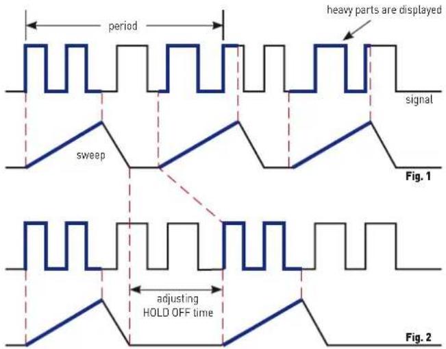
period heavy parts are displayed signal sweep Fig. 1 adjusting HOLD OFF time Fig. 2Fig. 1 shows the screen display with minimum hold-off time (basic setting). A double display is shown because different portions of the signal are displayed.
Fig. 2: Here, the hold-off time was adjusted such that always the same signal portions are displayed, a stable display is obtained.
In order to change the hold-off time, press the HOLD-OFF/ON button and turn the TIME/DIV 15 knob slowly CW until a stable display is found.
Double displays are also possible with pulse trains when the amplitudes alternately differ by a small amount. Careful setting of the trigger level and of the hold-off time may be required for correct displays.
Any time the hold-off time was changed from its basic minimum setting it should be reset because too long a hold-off time will cause the time base rep rate to decrease which can dim the display.
AUTOSET
See also the information given under AUTOSET 7 in the chapter Controls
As mentioned in the chapter Controls all front panel controls are electronically read out, hence the instrument can also be completely electronically controlled. This allows for a fully automatic signal-derived setting of all controls in the Yt mode. In most cases manual settings will be superfluous. When AUTOSET is activated, the instrument will enter the Yt mode if XY was selected; if it was already in Yt mode, the settings will remain unaffected unless ADD was selected which will be set to DUAL. In one-channel mode the sensitivity is automatically chosen so that the signal will be displayed with appr. 6 divisions; in DUAL channel mode each channel display will be appr. 4 divisions.
The foregoing and the description of the time base setting apply to signals which do not differ too much from a duty cycle of 1:1. The automatic selection of a suitable time base speed will show appr. 2 signal periods. With signals which contain several frequencies the settings obtained are governed by chance.
Pressing the AUTOSET button will have these results:
- The input coupling (AC, DC) remains unchanged resp. the last setting before switching to GND is resumed.
- Internal triggering.
- Automatic triggering.
- Automatic selection of the trigger source
- The trigger level will be set to the center of its range.
- VOLTS/DIV set to calibrated (variables off)
- TIME/DIV set to calibrated (variable off)
- AC or DC trigger coupling unchanged
- Magnifier off
- X and Y positions automatic
- Trigger slope selection unchanged
- Visible trace
Selecting AUTOSET will leave the selected AC or DC input coupling unchanged. In case DC trigger coupling was selected, this will not be changed to AC. The automatic triggering functions without peak-to-peak detection. The AUTOSET settings will override any former settings. In case variables were activated, they will be disabled, such that all settings will be calibrated. After AUTOSET was activated, manual control can be executed. Due to the reduced bandwidth in 1 and 2 mV/DIV these ranges will not be used in AUTOSET.

If a pulse signal is applied the duty cycle of which reaches or exceeds 1:400, an automatic display will in most cases become impossible. In such cases only the freerunning trace will be visible.
It is recommended to switch to normal trigger mode and to set the trigger point about 5 mm above or below the screen center. If the TRIG'd LED lights up, the signal was recognized. In order to render it visible, the time base speed and the sensitivity must be increased, however, the trace may dim so much that the pulse may remain invisible.
Component test
The oscilloscope HM400 has a built-in component tester which is activated by pressing the mode button COMP. The unit under test is connected to the two contacts right and left below the screen. After pressing the COMP button, the Y preamplifiers and the time base will be disconnected. While using the component tester, signals may be present at the inputs as long as the unit under test is not connected to any other circuit. It is possible to test components remaining in their circuits, but in such cases all signals must be disconnected from the three front panel BNC connectors! (See the following paragraph: "Test in circuits"). With the exception of the SELECT button 4, the ADJUST 2 buttons, and the X-POSITION 13 knob, and the X-MAG/x 10 12 button all other controls will be disabled. Two cables with 4 mm plugs are necessary to connect the unit under test to the component tester. After completion of the component test pressing the COMP button again is all that is needed to resume normal scope operation.

As outlined in the chapter Safety, all measurement connectors are connected to the mains safety earth (in proper operation). This implies also the COMP.TESTER contacts. As long as individual components are tested, this is of no consequence because these components are not connected to the mains safety earth.

If components are to be tested which are located in circuits or instruments, these circuits resp. instruments must be disconnected fi rst under all circumstances! If they are operated from the mains, the mains plug of the test object has to be pulled out. This ensures that there will be no loops between the scope and the test object via the safety earth which might cause false results.

Only discharged capacitors may be tested!
The test principle is quite simple. A generator within the HM400 generates a 50 Hz ±10 % sine wave which feeds the series connection of the test object and a sense resistor. The sine wave voltage is used for the X deflection and the voltage drop across the resistor for the Y deflection.
If the test object has only a real part such as a resistor, both deflection voltages will be in phase; the display will be a straight line, more or less slanted. Is the test object short-circuited, the line will be vertical (no voltage, current maximum). If the test object is open-circuited or missing a horizontal line will appear (voltage, but no current). The angle of the line with the horizontal is a measure of the resistance value, allowing for measurements of resistors between 20 Ω and 4.7 K.
Capacitors and inductors cause phase shift between voltage and current and hence between the deflection voltages. This will cause displays of ellipses. The location and the form factor of the ellipse are determined by the apparent impedance at 50 Hz. Capacitors can be measured between 0.1 and 1000 F.
- An ellipse with its longer axis horizontal indicates a high impedance (small capacitance or large inductance)
- An ellipse with its longer axis vertical indicates a low impedance (large capacitance or small inductance)
- An ellipse with its longer axis slanted indicates a relatively large resistive loss in series with the impedance of the capacitor or inductor.
With semiconductors the transition from the non-conducting to the conducting state will be indicated in their characteristic. As far as is possible with the available voltages and currents the forward and backward characteristics are displayed (e.g. with zener diodes up to 9 V). Because this is a two-pole measurement, the gain of a transistor can not be determined, however, the B-C, B-E, C-E diodes can be measured. Please
note that most bipolar transistors can only take an E-B voltage of appr. 5 V and may be damaged if this is exceeded, sensitive HF transistors take even much less! With this exception the diodes can be measured without fear of destruction as the maximum voltage is limited to 9 V and the current to a few mA. This implies, however, that a measurement of breakdown voltages > 9 V is not possible. In general this is no disadvantage because, if there is a defect in a circuit, gross deviations are to be expected which will point to the defective component.
Rather exact results may be achieved if the measurements are compared to those of intact components. This is especially true for semiconductors. The polarity of diodes or transistors can thus be identified if the lettering or marking is missing.
Please note that with semiconductors changing the polarity [e.g. by exchanging the COMP.TESTER and ground terminals] will cause the display to rotate 180 degrees around the screen center. More important in practice is the quick determination of plain shorts and opens which are the most common causes of requiring service.

It is highly recommended to observe the necessary precautions when handling MOS components which can be destroyed by static charges and even tribo electricity. The display may show hum if the base or gate connection of a transistor is open, i.e. it is not being tested. This can be verified by moving a hand closeby.
In-circuit tests
They are possible in many cases but deliver rarely clear results. By paralleling of real or complex impedances – especially if those are fairly low impedance at 50 Hz – there will be mostly great differences compared to individual components. If circuits of the same type have to be tested often (service), comparisons with intact circuits may help again. This is also quickly done because the intact circuit has not to be functional, also it should not be energized. Just probe the various test points with the cables of the component tester of the unit under test and the intact unit and compare the screen displays. Sometimes the unit under test may already contain an intact portion of the same type, this is e.g. the case with stereo circuits, push-pull circuits or symmetrical bridge circuits. In cases of doubt one side of the dubious component can be unsoldered, and this free contact should then be connected to the COMP.TESTER contact which is not identified as the ground contact. This will reduce hum pick-up. The contact with the ground symbol is connected to the scope chassis and is thus not susceptible to hum pick-up.
Function of the controls
1 POWER
Pushbutton switch with indications of off (0) and on (1) positions. After turn-on all LEDs will light up, the instrument performs a self-test. As soon as this has been successfully completed, the oscilloscope will switch to normal operation, all settings which were valid switching off will be resumed.
2 ADJUST - / +
Allows to change the value of diverse settings selected by SELECT 4
③ Indication LEDs
INTENS
The LED will light if the function intensity adjustment was selected by SELECT 7. With the buttons ADJUST - / + 2 the intensity may be
decreased resp. increased. It is recommended to set the intensity no higher than needed for easy viewing, this depends on signal parameters, oscilloscope settings and the ambient light conditions.
FOCUS
The LED will light up if the function focus adjustment was selected by SELECT 4. With the buttons ADJUST -/+ 2 the focus can be changed. The focus adjustment depends on the intensity, the lower the intensity, the better the focus. Also, the focus depends on the location of the trace on the screen, the best focus is always in the center and it decreases towards the edges. A reasonable focus setting is hardly possible with only the trace on screen. Due to the interaction between intensity and focus, the best procedure is this:
- Apply a sine wave signal which covers the whole screen.
- Set the intensity.
- Adjust the focus for a uniform well focussed display over most of the screen area.
Please note that the display of signals with a low rep rate at high sweep speeds will ask for a higher intensity setting, this will entail a readjustment of the focus.
TRACE
The LED will light up if the function trace rotation was selected by SELECT 4. With the buttons ADJUST - / + 2 the trace rotation can be adjusted. Due to the earth's magnetic field the trace may not be parallel to the graticule lines, adjust for exact parallelism. See also under "Trace Rotation" in the chapter "First time operation".
4 SELECT
This button allows to select and change the settings related to the trace in conjunction with the buttons ADJUST - / + ②. By pressing one of this buttons shortly the functions intensity, focus and trace rotation will be enabled in turn as indicated by the associated LEDs.
⑤ POSITION 1 + POSITION 2, CH1 + CH2
These knobs control the trace position of channel 1 respectively cannel 2. In ADD mode both position controls will be effective. In XY mode the Y position control is disabled; the X position is always controlled by the knob HORIZONTAL position [13].
Measurement of DC voltages
If there are no voltages present at the Y amplifier inputs 29 CH1 resp. CH2, or if GND was selected, the trace positions correspond to zero volts, however, they are also influenced by the position controls! (The trace will be visible only if automatic triggering AUTO 8 was selected.)
In order to measure a DC voltage, first the input must be disconnected or switched to GND. Then it is up to the user to choose a reference trace position with the respective position control, i.e. 5 for channel 1. Then the DC voltage can be connected resp. the input switched from GND to DC; the trace will move by an amount depending on the polarity and value of the dc voltage and the sensitivity (and probe) selected. The same is true for measuring the dc content of any signal.
In regular operation, the position controls will mostly be set to the screen center representing zero. It should be kept in mind, that it can not be just assumed that a trace position at the screen center corresponds to zero volts, this has to be checked by switching to GND.
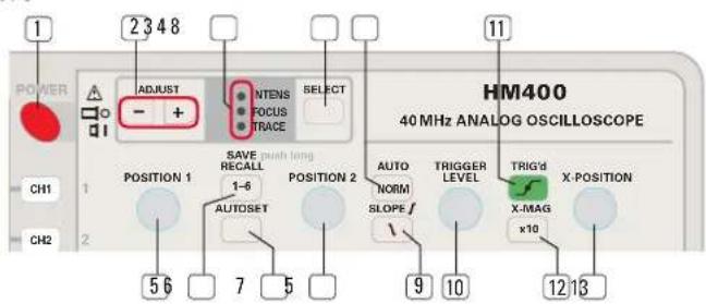
text_image
POWER 1 2 3 4 8 ADJUST - + INTENS FOCUS RELECT PHASE TRACE 11 HM400 40 MHz ANALOG OSCILLOSCOPE CH1 1 CHANGE SAVE RECALL 1-6 POSITION 2 AUTO NORM TRIGGER LEVEL TRIG'd X-MAG X-POSITION CH2 5 6 7 5 9 10 12 136 SAVE / RECALL
This button allows access to the settings memories in conj with the MODE buttons 32. The oscilloscope has 6 settings memories, settings can be stored or recalled.
SAVE: In order to store a setting, fi rst press the SAVE/RECALL button for some time, until the MODE buttons 32 start blinking. By pressing the respective mode button, the associated memory will be called and the present setting will be stored, the mode button LEDs will then extinguish. If the SAVE/RECALL button was pressed inadvertently, this can be repaired by pressing it again or any other button except the mode buttons.
RECAL: For recalling press the SAVE/RECALL button just shortly, the mode buttons 32 will light up. By pressing the desired mode button, the settings stored in that memory will be taken over by the oscilloscope. The mode buttons will then extinguish. If the SAVE/RECALL button was pressed inadvertently, this can be repaired by pressing it again or any other button except the mode buttons.

Please note that the signal presently displayed should be similar to that which was present at the time the setting was stored! If any other signal (frequency, amplitude) is being displayed when recalling, seemingly „false“ displays may result as the recalled settings may not be appropriate for the other signal.
7 AUTOSET
See also the chapter AUTOSET. Pressing this button will cause the instrument to automatically choose a setting which generates a meaningful display. If the modes XY or Component Tester were active before pressing this button, AUTOSET will switch to the Yt mode last used (CH 1, CH 2, DUAL).
8 AUTO / NORM -LED button
By pressing this button shortly the trigger mode will be alternated between AUTO and NORMAL triggering. The LED will light up when NORMAL triggering is selected.
AUTO: Automatic triggering is available with or without peak-to-peak measurement. The TRIGGER LEVEL 10 knob is active in both cases. The automatic triggering circuit will also provide a bright baseline if there is no signal or an insufficient one for triggering. See the specifications for the lower frequency limit below which automatic triggering does not function, i.e. the display will not be triggered.
With peak-to-peak triggering the range of the TRIGGER LEVEL 10 control will be automatically adjusted to the present peak-to-peak signal level. Without this function there is no relationship between the signal amplitude and the range of the trigger level control, hence the trigger level may then be set too high or too low. The automatic triggering circuit will display the signal, but it will not be triggered.
Whether peak-to-peak triggering is active or not depends on the operating mode and the trigger coupling selected. By turning the TRIGGER LEVEL knob and looking for the start of the display, it will be obvious whether it is active or not.
NORM: This is called the normal mode because it is the only one which allows triggering of complex waveforms and of very low frequency signals; in this mode the automatic and the peak-to-peak functions are disabled. A disadvantage of this mode is the fact that there will no trace visible if there is no signal, if the signal is insufficient for triggering or if the TRIGGER LEVEL 10 control is set inappropriately for the signal applied. The best procedure is to use auto peak-to-peak triggering as the standard and use NORM only if necessary.
⑨ SLOPE - LED button
This button selects either the plus ( ) or the minus ( ) slope of the triggering signal. The LED will light up if the negative slope is selected.
10 TRIGGER LEVEL - Knob
With the control the level of the triggering signal is determined at which the trigger comparator will respond and generate a signal to start the time base. The slope is selected with the above slope button. The trigger point is the point on the signal at which the display starts, it can be moved along the signal with the TRIGGER LEVEL control. See also the explanations in the foregoing paragraphs about automatic, peak-to-peak and normal triggering. In some combinations it is possible to lose triggering if the trigger level control is not set appropriately. Pressing AUTOSET 7 will restore a triggered display in most cases.
11 TRIG'd - LED
This LED will light if up the time base receives start pulses from the trigger comparator. Depending on the frequency of the pulses the LED will blink or appear to light steadily.
12 X-MAG/ x10 - Button with „x 10" LED
This button switches the X magnifi er on/off, the LED wil indicate if the magnifi er is on. The magnifi ed portion of the display can be shifted with the X-POSITION 13 control. The magnifi cation expands the display around the screen center, hence the normal procedure is to move the portion to be magnifi ed to the center with the X-POSITION control and then to activate the magnifier. In XY mode the magnifier is disabled.
13 X-POSITION
With this knob the display can be moved in X direction (horizontally). See the paragraph above for its use together with the magnifi er.
14 VOLTS/DIV, CH1 + CH2 - knobs
These are dual function knobs: it is used to select the appropriate sensitivity for the signal of each channel's input, by pressing it shortly it will assume the "Variable" [VAR] function (see below), while this is active, the sensitivity indicators (ring of LEDs around the knob) will blink as a warning that the sensitivity is now uncalibrated. The knob is only enabled if CH1 or CH2 was activated or selected as the trigger source (CH1 or CH2 only, dual trace, ADD, XY).
Sensitivity selection (Input attenuator)
If the sensitivity indicator LED does not blink, the sensitivity selected will be calibrated. The sensitivity can be decreased CCW to 20 V/DV and increased CW to 1 mV/DIV in 1 - 2 - 5 steps.
VAR [CH1 + CH2]
By pressing the VOLTS/DIV ^[14] knobs shortly, its function will be changed to "Variable" which will be indicated by blinking of the sensitivity indicator LEDs around the knob. Pressing it again will restore the calibrated sensitivity, the blinking will stop. As long as the variable function is enabled, the display will be uncalibrated! CCW rotation will decrease the sensitivity, CW rotation will increase it. The variable allows hence to bridge the 1 – 2 – 5 steps of the sensitivity switch. If any of the two limits of the variable range is reached, an acoustic signal will indicate this. This function is frequently used e.g. for measuring rise times: because the rise time is defined from 10 to 90 % of the full amplitude, the variable comes in handy to set the (uncalibrated) signal amplitude e.g. precisely to 6 divisions peak-to-peak; by shifting the display horizontally with the X position control, the rise time can be read from 6 mm from the bottom to 6 mm below the top of the waveform.
15 TIME/DIV - knob
This knob has a triple function:
- It selects the time base speed.
- By pressing it shortly, it will assume the "Variable" VAR function, this will be indicated by blinking of the LEDs around the knob.
- After pressing the HOLD-OFF/ON 27 button, it will assume the function of hold-off time adjustment, this will be indicated by the button 27 lighting up, refer to 27.
The time base speed is selectable in 1 – 2 – 5 steps, turning the knob CCW, it can be decreased to 0.2 s/DIV, turning it CW, it can be increased to 100 ns/DIV, the speed will be indicated by the LEDs around the knob,
e.g. 10 μs (/DIV). By activating the X-MAG / x10 12, the speed can be further increased by a factor of 10 up to the maximum of 10 ns/DIV.
VAR: If the variable function was selected by pressing the knob shortly, the time base speed can be reduced by turning it CCW and increased by turning it CW, uncalibrated. Whenever the limits are reached, an acoustic signal will be heard. By pressing the knob again, the function variable can be left any time and calibrated operation resumed.
Hold-off time adjustment: Please rever to item 27.
16 CH 1 - LED button
This button selects CH 1 as the trigger source. In all operating modes of the vertical amplifier except XY, CH 1 can be selected as the active internal trigger source by pressing this button which will be indicated by the LED lighting up.

INTERNAL TRIGGERING: The trigger signal is taken off internally.
17 CH 2 - LED button
This button selects CH 2 as the trigger source. In all operating modes of the vertical amplifier except XY, CH 2 can be selected as the active internal trigger source by pressing this button which will be indicated by the LED lighting up.
18 LINE - LED button
This button selects the line (mains) as the trigger source. In all operating modes of the vertical amplifier except XY the line (mains) can be selected as the active trigger source which will be indicated by the LED lighting up.

LINE TRIGGERING: The trigger signal is not derived from an input signal but from the mains and taken from the power supply.
19 EXT - LED button
This button selects the external input as the trigger source. In all operating modes of the vertical amplifier except XY pressing this button will select the external BNC input EXT.TRIG/Z-INP 31 as the trigger source which will be indicated by the LED lighting up. The external Z-INP for intensity modulation will be disabled.

EXTERNAL TRIGGER SOURCE: The trigger signal is not taken from the measuring signals but from an external source.
20 AC - LED button
In all operating modes of the vertical amplifier except XY pressing this button shortly will select AC trigger coupling which will be indicated by the LED lighting up.
21 DC - LED button
In all operating modes of the vertical amplifier except XY pressing this button shortly will select DC trigger coupling which will be indicated by the LED lighting up. The peak-to-peak detection will be disabled.
22 LF - LED button
In all operating modes of the vertical amplifi er except XY pressing this button will insert a low pass filter (see the specifications) into the trigger path which will be indicated by the LED lighting up. The low pass will suppress high frequency interference which could disturb triggering.
23 TV - LED button
In all operating modes of the vertical amplifier except XY pressing this button shortly will activate the TV trigger separator which will be indicated by the LED lighting up. The following remarks apply to the PAL TV standard.
For frame synchronization the TIME/DIV 15 knob should be set between 0.2 s/DIV and 1 ms/DIV, at 2 ms/DIV a full frame will be displayed.

text_image
14 VOLTS/DIV 5 2 1 50 VAR 1 2 5 10 2 5 5 10 20 V mV 14 VOLTS/DIV 5 2 1 50 TRIGGER 20 CH 1 AC 10 CH 2 DC 5 LINE LF 2 EXT TV 21 TIME/DIV 50 ms 2.1 50 VAR 20 μs 1 2 5 10 5 10 20 V mV 1 DC AC GND DC AC GND INV CH1 INPUTS 1MΩ/1.15pF max. max. 40D Vp CH2 PROBE ADJUST 1kHz / MHz ca. 0.2 Vpp EXT. TRIG / Z-INP 30 27 31 28 X-IPN CH1 CAT I 24 29 25 24 25 29 26 30 1MΩ II 1.6pF max 100V pFor line synchronization the TIME/DIV 15 knob should be set between 0.5 ms/DIV and 0.1 μs/DIV. At 10 μs/DIV single lines can be displayed, about 1½ lines will be visible.
24 DC/AC - LED buttons for CH1 + CH2
By pressing these buttons shortly, the coupling of channel 1 or 2 resp. can be alternated between DC and AC, the LED will light up if AC is selected.
25 GND - LED buttons for CH 1 + CH2
By pressing these buttons shortly, the input of the channel 1 or 2 preamplifi er will be connected to ground resp., which will be indicated by the LED lighting up. The signal present at the input BNC connector can not influence the trace. In Yt-mode with auto trigger an undeflected trace will be visible (zero-volts trace position). In XY-mode there will be no deflection in X and Y directions respectively.
26 INV - LED button for CH 2
By pressing this button shortly, the display of the channel 2 signal can be alternated between normal and inverted. The LED will light up if inversion is selected.
27 HOLD-OFF/ON - LED button
By shortly pressing this button, adjustment of the hold-off time by turning the knob/TIME/DIV 15 will be activated which will be indicated by the LED lighting up. Refer to item 15 for information about the triple function of this knob. The knob allows an increase of the hold-off time from its minimum value by turning it CW, if the end of the range is reached, an acoustic signal will be heard. Also, when the knob is turned CCW, the acoustic signal will sound when the minimum value is reached. As soon as the hold-off time adjustment is disabled by again pressing 27, the hold-toff time will be automatically reset to its minimum value. By shortly pressing the TIME/DIV knob while 27 is activated, it is possible to alternate between setting the time/div. and hold-off time adjustment. See also under „Hold-off time adjustment”.
28 Z-INP - LED button
By shortly pressing this button, the function of the input EXT.TRIG / Z-INP 31 is changed from external trigger input to external intensity modulation input which will be indicated by the LED lighting up. If external triggering or the COMPONENT TESTER are selected, no intensity modulation will be possible resp. it will be disabled. 0 V at the input will not change the trace intensity, with 5 V TTL level the trace will be fully suppressed, higher voltages are not allowed.
29 INPUT CH1 + CH2 - BNC connectors
These are the CH1 and CH2 inputs in Yt-mode and the X input in XY mode. The ground of this connector is connected to the chassis and thus to the mains safety earth. The buttons DC/AC 24 , GND 25 and INV 26 (CH2 only) correspond to this input.
30 PROBE ADJUST Contact
At this contact a square wave signal of 1 kHz or 1 MHz with a rise time of <5 ns and an output impedance of 50 Ω is available for the adjustment of probes other than 1:1, the amplitude is appr. 0.2 Vpp. For probe adjustment purposes neither the frequency, nor the duty cycle nor the exact amplitude are of concern.
The frequency of the square wave depends on the setting of the TIME/DIV 15 selector: between 0.2 s/DIV and 100 s/DIV the frequency will be 1 kHz and between 50 s/DIV to 100 ns/DIV it will be 1 MHz. See the chapter „First time operation and initial settings and „Probe adjustment and application.“
PROBE ADJUST: This contact is the ground connection for the probe.
31 EXT.TRIG/Z-INP - BNC connector
This is either the external trigger or the external intensity modulation input. The input impedance is 1 MΩ II 15 pF. The ground of this connector is connected to the chassis and thus to the mains safety earth. By shortly pressing the Z-INP 28 button the function of the input can be changed.
EXT.TRIG: This BNC connector is the external trigger input if the Z-INP LED is extinguished. The trigger source is selected with the buttons [16] to [19] ; if external triggering is selected, the Z input will be automatically disabled.
Z-INP: Z modulation is only possible if the Z-INP[28] button is illuminated. It is not possible to combine Z modulation with either external triggering or with the "Component Tester" function, selecting one of these will disable the Z modulation. With 0 V at this input the trace intensity will not be influenced, with 5 V TTL level the trace will be fully suppressed; do not apply higher voltages.
32 MODE select buttons with LED
Selection of CH1, CH 2, DUAL, ADD, XY and Component Tester modes, the active mode is indicated by the respective LED lighting up. Change of modes just requires shortly pressing the button of the desired function. The modes do not affect the trigger control status.
CH 1: This button has a dual function: it either selects single channel 1 operation or allows access to the settings memory 1. Single channel CH 1 operation will automatically also select CH 1 as the trigger source unless external or line triggering were selected, this will be indicated by the trigger source button 16 lighting up. The last function of the VOLTS/DIV 14 knob will be preserved. All control elements belonging to this channel will be activated.
CH 2: This button has a dual function: it either selects single channel 2 operation or allows access to the settings memory 2. Single channel CH2 operation will automatically also select CH2 as the trigger source unless external or line triggering were selected, this will be indicated by the trigger source button 17 lighting up. The last function of the VOLTS/DIV 14 knob will be preserved. All control elements belonging to this channel will be activated.
DUAL: This button has a dual function: it either selects the dual channel mode or allows access to the settings memory 3. The trigger settings existing before selecting DUAL mode remain valid unless then now changed intentionally. In DUAL mode the LED will light up. In dual channel mode the channel switching may be alternated or chopped.
ADD: This button has a dual function: it either selects the ADD mode or allows access to the settings memory 4. The trigger settings existing before switching to ADD remain valid unless they are now changed intentionally. The active ADD mode is indicated by the LED lighting up.
Addition of CH 1 and CH 2 mode:
In this mode the signals of channels 1 and 2 are algebraically added, if CH2 is inverted CH1 - CH2 will be displayed. CH2 - CH1 is not available.
For a correct result the settings of the two VOLTS/DIV selectors must be identical. The vertical position is now influenced by both Y position controls. See the respective paragraph in the introductory part of this manual for further information, because the use of this mode requires much care in order to avoid false measurements!
XY: This button has a dual function: it either selects the XY mode or it allows access to the settings memory 5. If XY is active, the LED will light up.
XY operation: In XY mode the following displays/indicators will turned off:
- The time base speed display.
- The displays/indicators of trigger source, slope, coupling, hold-off time.
The existing trigger control settings before switching to XY are preserved, however.
Also all controls belonging to these displays/indicators will be disabled. The POSITION 1 ^5 and the TRIGGER LEVEL ^10 knobs are disabled, too. The X position will remain to be controlled by the X-POSITION ^13 knob.
COMP: This button has a dual function: it either selects the COMPONENT TESTER function or it allows access to the settings memory 6. If COMPONENT TESTER mode is selected, the LED will light up. By pressing any other button the COMPONENT TESTER will be disabled.
Operation of the COMPONENT TESTER
The button COMP alternates between scope and Component TESTER operation; when returning to scope operation, the last settings will be resumed. See also the chapter "Component Tester". In this mode the following controls and LED indicators are important:
- ADJUST -/+ buttons 2, with their LEDs: INTENS, FOCUS, and TRACE 3
- X-POSITION knob13
The test of electronic components is a two-pole measurement. The unit to be tested is connected to the two contacts below the screen by using 4 mm plugs
33 COMPONENT TESTER - 2 contacts for 4 mm plugs
The test leads from the unit under test are plugged in here, the left contact is connected to the chassis and thus to the mains safety earth. For DC or low frequency measurements it may be used as a ground terminal.
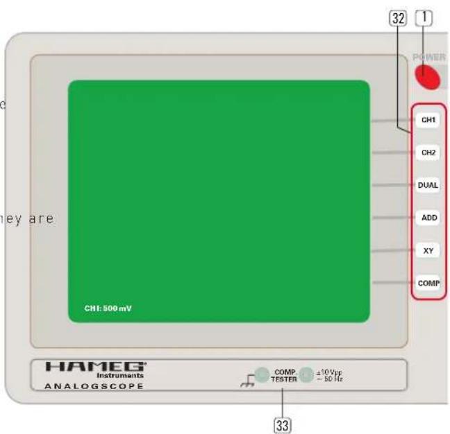
text_image
32 1 POWER CH1 CH2 DUAL ADD XY COMP CH1 500 mV HAMEG Instruments ANALOGSCOPE COMP. ±10 Vpp - 50 Hz 33CE
HAMEG Instruments
KONFORMITÄTSERKLÄRUNG DECLARATION OF CONFORMITY DECLARATION DE CONFORMITE DECLARACIÓN DE CONFORMIDAD
Hersteller / Manufacturer / Fabricant / Fabricante: HAMEG Instruments GmbH · Industriestraße 6 · D-63533 Mainhausen
natural_image
Green grid background with a white outline on the right edge (no text or symbols)natural_image
Abstract green grid pattern with faint vertical bars and horizontal lines, no text or symbols presentnatural_image
Green grid background with a white line segment on the right edge (no text or symbols)Return Material Authorization - RMA
natural_image
Abstract geometric pattern with a white line on a teal grid background (no text or symbols)natural_image
Abstract green grid pattern with faint vertical light streaks on the right side (no text or symbols)natural_image
Green grid background with a white L-shaped line on the right edge (no text or symbols)Return Material Authorization (RMA)
③ Indication LEDs 77
14 VOLTS/DIV (boutons, CH1 + CH2) 78
Mesure de tensions continues
Instruments ANALOGSCOPE
COMP. ±10 Vpp TESTER - 50 Hz
