Royal SMP 400-S - Surface pump EINHELL - Free user manual and instructions
Find the device manual for free Royal SMP 400-S EINHELL in PDF.
User questions about Royal SMP 400-S EINHELL
0 question about this device. Answer the ones you know or ask your own.
Ask a new question about this device
Download the instructions for your Surface pump in PDF format for free! Find your manual Royal SMP 400-S - EINHELL and take your electronic device back in hand. On this page are published all the documents necessary for the use of your device. Royal SMP 400-S by EINHELL.
USER MANUAL Royal SMP 400-S EINHELL
line
| Q l/min | m | | ------- | --- | | 0 | 5.7 | | 20 | 5.6 | | 40 | 5.2 | | 50 | 4.9 | | 70 | 4.3 | | 90 | 3.6 | | 100 | 3.0 | | 120 | 2.3 | | 130 | 1.6 | | 140 | 1.0 | | 150 | 0.0 |GB
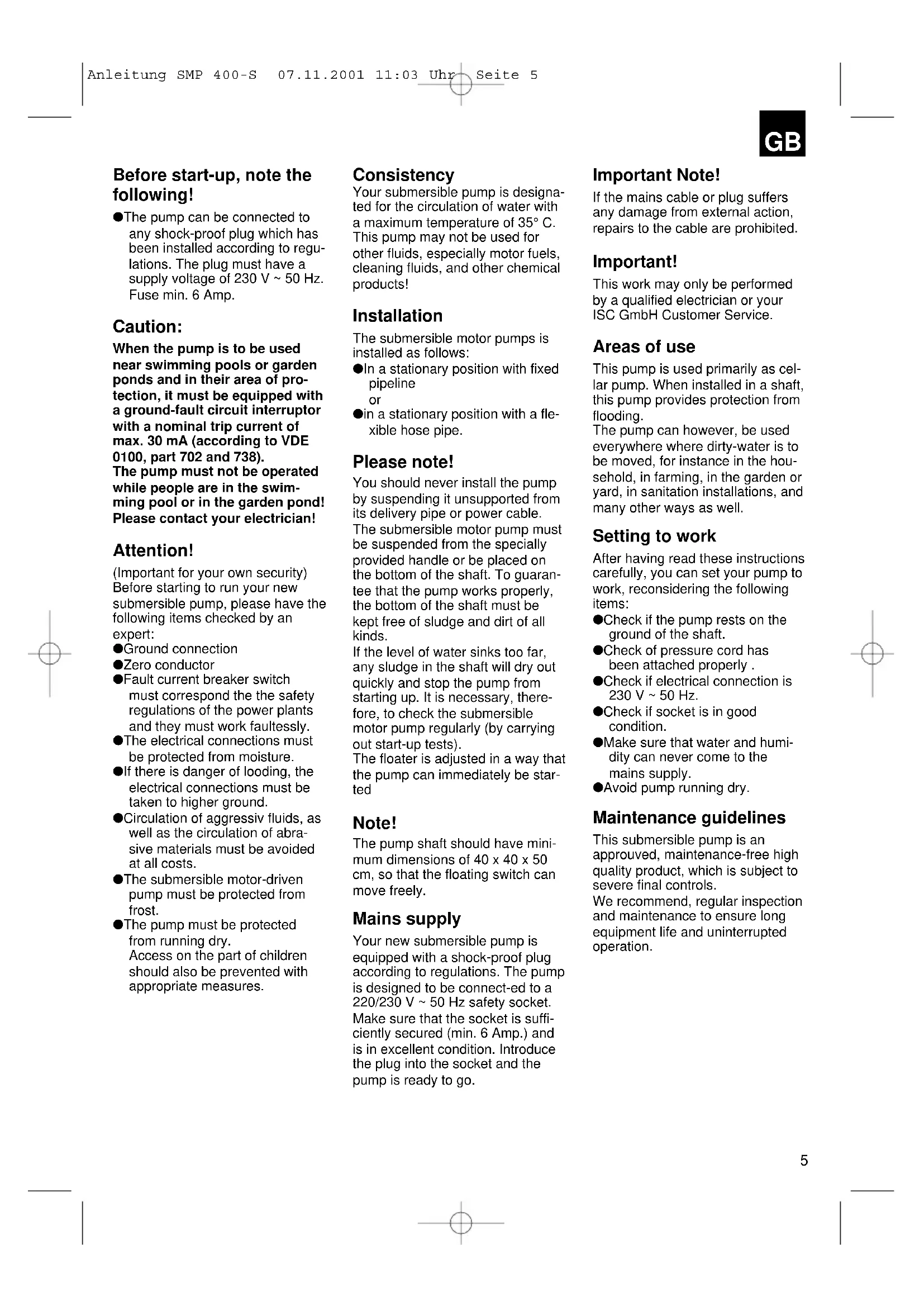
Before start-up, note the following!
●The pump can be connected to any shock-proof plug which has been installed according to regulations. The plug must have a supply voltage of 230 V \~ 50 Hz. Fuse min. 6 Amp.
Caution:
When the pump is to be used near swimming pools or garden ponds and in their area of protection, it must be equipped with a ground-fault circuit interruptor with a nominal trip current of max. 30 mA (according to VDE 0100, part 702 and 738). The pump must not be operated while people are in the swimming pool or in the garden pond! Please contact your electrician!
Attention!
(Important for your own security) Before starting to run your new submersible pump, please have the following items checked by an expert:
●Ground connection
●Zero conductor
●Fault current breaker switch must correspond the safety regulations of the power plants and they must work faultessly.
●The electrical connections must be protected from moisture.
- If there is danger of looding, the electrical connections must be taken to higher ground.
●Circulation of aggressiv fluids, as well as the circulation of abrasive materials must be avoided at all costs.
●The submersible motor-driven pump must be protected from frost.
●The pump must be protected from running dry.
Access on the part of children should also be prevented with appropriate measures.
Consistency
Your submersible pump is designated for the circulation of water with a maximum temperature of 35^ C. This pump may not be used for other fluids, especially motor fuels, cleaning fluids, and other chemical products!
Installation
The submersible motor pumps is installed as follows:
●In a stationary position with fixed pipeline or
●in a stationary position with a flexible hose pipe.
Please note!
You should never install the pump by suspending it unsupported from its delivery pipe or power cable. The submersible motor pump must be suspended from the specially provided handle or be placed on the bottom of the shaft. To guarantee that the pump works properly, the bottom of the shaft must be kept free of sludge and dirt of all kinds.
If the level of water sinks too far, any sludge in the shaft will dry out quickly and stop the pump from starting up. It is necessary, therefore, to check the submersible motor pump regularly (by carrying out start-up tests).
The floater is adjusted in a way that the pump can immediately be started
Note!
The pump shaft should have minimum dimensions of 40 x 40 x 50 cm, so that the floating switch can move freely.
Mains supply
Your new submersible pump is equipped with a shock-proof plug according to regulations. The pump is designed to be connected to a 220/230 V \~ 50 Hz safety socket. Make sure that the socket is sufficiently secured (min. 6 Amp.) and is in excellent condition. Introduce the plug into the socket and the pump is ready to go.
Important Note!
If the mains cable or plug suffers any damage from external action, repairs to the cable are prohibited.
Important!
This work may only be performed by a qualified electrician or your ISC GmbH Customer Service.
Areas of use
This pump is used primarily as cellar pump. When installed in a shaft, this pump provides protection from flooding.
The pump can however, be used everywhere where dirty-water is to be moved, for instance in the household, in farming, in the garden or yard, in sanitation installations, and many other ways as well.
Setting to work
After having read these instructions carefully, you can set your pump to work, reconsidering the following items:
- Check if the pump rests on the ground of the shaft.
●Check of pressure cord has been attached properly. - Check if electrical connection is 230 V \~ 50 Hz.
- Check if socket is in good condition.
●Make sure that water and humidity can never come to the mains supply.
●Avoid pump running dry.
Maintenance guidelines
This submersible pump is an approuved, maintenance-free high quality product, which is subject to severe final controls.
We recommend, regular inspection and maintenance to ensure long equipment life and uninterrupted operation.
GB
Important! Note!
- Remove the mains plug before all maintenance work.
●In the event that the pump is often transported in the course of operation, it should be cleaned out with clear water after every use.
●In case of stationary installation, the function of the loating switch should be checked every 3 months.
●All fibrous particles which may have built-up inside the pump housing should be removed with a water jet.
●Every 3 months the shaft ground and as should be cleaned from mud. - Remove deposits on the floater with clear water.
Cleaning the impeller wheel
If too much sediment collects in the pump case, you must dismantle the bottom section of the pump as follows:
-
Using two screwdrivers as levers, ease the bottom cover off the intake housing
-
You can now clean the impeller wheel with clear water.
Caution! Never allow the pump to stand on or lean against the impeller wheel! - Reassemble in reverse order.
Setting the ON/OFF operating point
The ON and OFF operating point of the float switch can be set by adjusting the float switch in its latching holder.
Before you put the pump into operation, please check the following:
●The float switch must be installed so that the level of the ON operating point and the level of the OFF operating point can be reached easily and with little force. To check this, place the pump in a vessel filled with water, raise the float switch carefully by hand and then lower it again. As you do so, note whether the pump switches on and off.
●Make sure that the distance between the float switch head and the latching holder is not too small. Proper operation is not guaranteed if the gap is too small.
- When you set the float switch, make sure that it does not touch the base before the pump switches off. Caution! Risk of dry-running.
Incidents – Causes – Remedies
| Incidents | Causes | Remedies |
| Pumpe does not start | – No mains supply– Floater does not switch | – Check mains supply– Bring floater in a higher position |
| No flow | – Inlet sieve is clogged– Pressure hose in bent | – Clean inlet sieve water jet– Reset hose |
| Pump does not switch off | – Floater cannot sink down | – Place pump properly on shaft ground |
| Insufficient flow | – Inlet sieve is clogged– Reduced pumping capacity by dirty and abrasive water | – Clean inlet sieve– Clean pump and replace worn-out parts |
| Pump switches of after short operating period | – Thermal cutout stops pumps due to dirty water– Water too hot. Thermal-cutout stops pump | – Remove mains plug. Clean pump and shaft– Make sure that a water temperature of max. 35°C is not exceed |
Guarantee note:
Not covered by guarantee:
●Destruction of rotating mechanical seal by dry running or addition of foreign bodies in water
●Blockage of running wheel through foreign bodies
●Transport damage
●Damage caused by unauthorised persons
Ordering spare parts
- Please provide the following information if you need any spare parts:
- Type of unit
- Article number
- Identification number
- Number of the required spare part
Technical data
| ROYAL SMP 400-S | |
| Power supply 230V ~ 50Hz | |
| Power consumption 400 Watt | |
| Delivery rate max.. 9000 l/h | |
| Delivery height max 5,5 m | |
| Immersion depth max. 4,5 m | |
| Water temperature max. 35°C | |
| Hose connection 5/4" threaded end | |
| Foreign bodies up to dia. 30 mm | |
| Switching point high: ON ca. 40 cm | |
| Switching point high: OFF ca. 15 cm | |
| Article No. 41.708.90 |
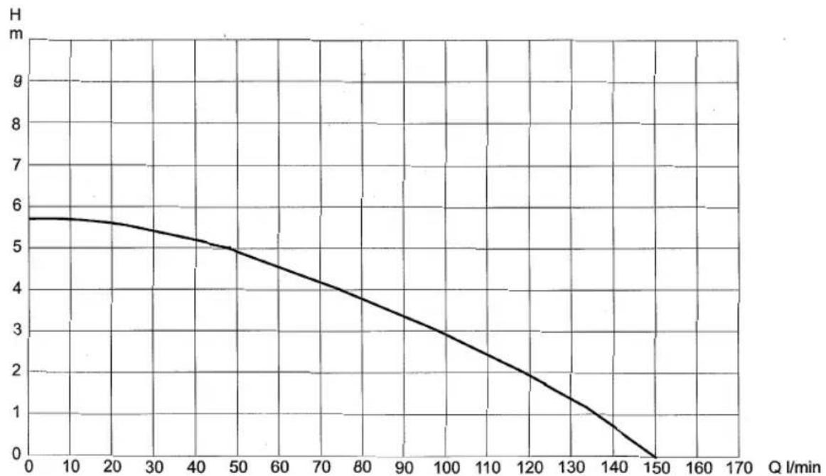
Characteristic curve
line
| Q l/min | H | | ------- | --- | | 0 | 5.7 | | 20 | 5.6 | | 40 | 5.2 | | 50 | 4.9 | | 70 | 4.3 | | 80 | 3.8 | | 90 | 3.3 | | 100 | 2.8 | | 120 | 2.0 | | 130 | 1.3 | | 140 | 0.6 | | 150 | 0.0 |F
Attention! Important!
line
| Q l/min | H | | ------- | --- | | 0 | 5.7 | | 20 | 5.5 | | 40 | 5.0 | | 60 | 4.5 | | 80 | 4.0 | | 100 | 3.5 | | 120 | 2.5 | | 140 | 1.5 | | 150 | 0.0 |NL
line
| Q l/min | H | | ------- | --- | | 0 | 5.7 | | 10 | 5.6 | | 20 | 5.4 | | 30 | 5.2 | | 40 | 5.0 | | 50 | 4.8 | | 60 | 4.5 | | 70 | 4.2 | | 80 | 3.9 | | 90 | 3.6 | | 100 | 3.3 | | 110 | 2.9 | | 120 | 2.5 | | 130 | 2.1 | | 140 | 1.6 | | 150 | 0.0 | | 160 | 0.0 | | 170 | 0.0 |FIN
line
| Q l/min | H | | ------- | --- | | 0 | 5.7 | | 20 | 5.5 | | 40 | 5.0 | | 60 | 4.5 | | 80 | 4.0 | | 100 | 3.5 | | 120 | 2.5 | | 140 | 1.5 | | 150 | 0.0 |N
line
| Q l/min | H | | ------- | --- | | 0 | 5.7 | | 10 | 5.6 | | 20 | 5.4 | | 30 | 5.1 | | 40 | 4.8 | | 50 | 4.5 | | 60 | 4.1 | | 70 | 3.7 | | 80 | 3.3 | | 90 | 2.9 | | 100 | 2.5 | | 110 | 2.1 | | 120 | 1.7 | | 130 | 1.3 | | 140 | 0.9 | | 150 | 0.5 | | 160 | 0.1 | | 170 | 0.0 |GR
line
| Q l/min | H | | ------- | --- | | 0 | 5.7 | | 10 | 5.6 | | 20 | 5.4 | | 30 | 5.1 | | 40 | 4.8 | | 50 | 4.5 | | 60 | 4.1 | | 70 | 3.7 | | 80 | 3.3 | | 90 | 2.9 | | 100 | 2.5 | | 110 | 2.1 | | 120 | 1.7 | | 130 | 1.3 | | 140 | 0.8 | | 150 | 0.0 |
line
| Q l/min | H | | ------- | --- | | 0 | 5.7 | | 10 | 5.6 | | 20 | 5.4 | | 30 | 5.1 | | 40 | 4.8 | | 50 | 4.5 | | 60 | 4.1 | | 70 | 3.7 | | 80 | 3.3 | | 90 | 2.9 | | 100 | 2.5 | | 110 | 2.1 | | 120 | 1.7 | | 130 | 1.3 | | 140 | 0.8 | | 150 | 0 |DK
line
| Q l/min | H | | ------- | --- | | 0 | 5.7 | | 10 | 5.6 | | 20 | 5.4 | | 30 | 5.1 | | 40 | 4.8 | | 50 | 4.5 | | 60 | 4.1 | | 70 | 3.7 | | 80 | 3.3 | | 90 | 2.9 | | 100 | 2.5 | | 110 | 2.1 | | 120 | 1.7 | | 130 | 1.3 | | 140 | 0.8 | | 150 | 0.0 |text_image
Exploded view diagram of a spray gun with numbered parts for identificationErsatzteilliste
ROYAL SMP 400-S
The guarantee period begins on the sales date and is valid for 1 year.
Responsibility is assumed for faulty construction or material or functional defects.
Any necessary replacement parts an necessary repair work are free of charge.
We do not assume responsibility for consequential damage.
Your customer service partner
F GARANTIE EINHELL
⑤ EINHELL GARANTIBEVIS
DK EINHELL GARANTIBEVIS
Eschenstraße 6 · D-94405 Landau/Isar (Germany)
15 Warwick House Ind. Park, Banbury Road, Sautham, Warwickshire CV 33 OPS
F Agence Commerciale Kettering
DK Danish Trading Co. Silkeborg ApS
Rodelundvej 11 - Rodelund
DK-8653 Them
Technical changes subject to change