
BFV846 - TV Stand SANUS - Free user manual and instructions
Find the device manual for free BFV846 SANUS in PDF.

| Product Type | TV Stand |
| Brand | Sanus |
| Model | BFV846 |
| Color | Black (estimated) |
| Material | Natural wood and tempered glass |
| TV Compatibility | Flat screens only (no CRT) |
| Approximate dimensions (W x D x H) | 120 x 40 x 50 cm |
| Approximate weight | 25 kg |
| Maximum load capacity | Up to 30 kg (estimated) |
| Mounting options | Wall mounting possible (kit included) |
| Wall mounting type | On wood studs or concrete/concrete blocks |
| Wood care | Dust with a soft dry cloth; use a damp (not wet) cloth, then dry |
| Glass care | Regularly check for chips or cracks; stop using if damaged |
| Anti-tip safety | Center the TV on the stand to prevent tipping |
| Box contents | Panels, hardware, assembly instructions |
| Required tools | Screwdriver, drill (for wall mounting) |
Frequently Asked Questions - BFV846 SANUS
User questions about BFV846 SANUS
0 question about this device. Answer the ones you know or ask your own.
Ask a new question about this device
Download the instructions for your TV Stand in PDF format for free! Find your manual BFV846 - SANUS and take your electronic device back in hand. On this page are published all the documents necessary for the use of your device. BFV846 by SANUS.
USER MANUAL BFV846 SANUS
natural_image
Line drawing of a wooden workbench with a vertical support structure and a separate view of its frame (no text or symbols)INSTRUCTION MANUAL
If you have any questions along the way, just give us a call. 1-800-359-5520. We're ready to help!
Before You Begin
CAUTION: Avoid potential personal injuries and property damage!
- Do not use this product for any purpose not explicitly specified by manufacturer
- If you do not understand these instructions, or have doubts about the safety of the installation, assembly or use of this product, contact Customer Service or call a qualified contractor
● Manufacturer is not responsible for damage or injury caused by incorrect assembly or use
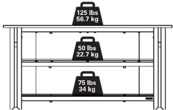
Weight Limits
Without Pillar Kit With Pillar Kit
bar
| Weight (lbs) | Weight (kg) | | ------------ | ----------- | | 125 | 56.7 | | 50 | 22.7 | | 75 | 34 |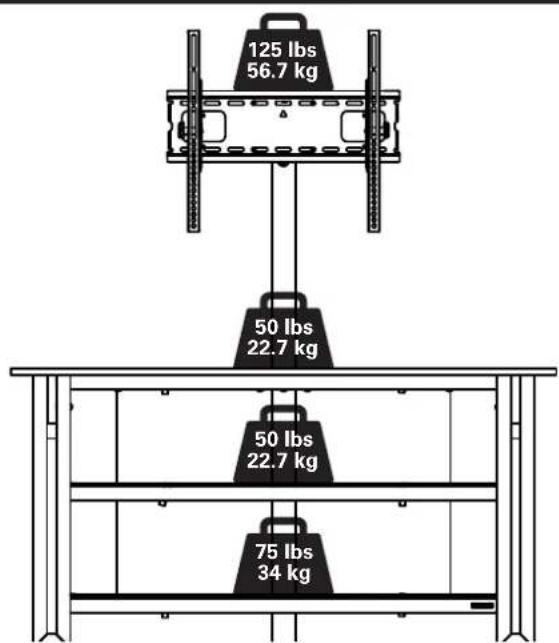
Cautions and Care
CAUTION: Avoid potential personal injuries and property damage!
- Tempered glass has been chosen for this product because of its strength and safety characteristics. However, tempered glass should still be handled with care to avoid possible property damage or personal injury.
- Mishandling during shipping, assembly, or use may result in damage that can weaken the tempered glass.
• Periodically check the glass to look for chips, cracks, or deep scratches. - If chips, cracks, or deep scratches are found, discontinue use and contact customer service.
CARE INSTRUCTIONS
For wood with a natural finish, dust regularly with a soft dry cloth. When needed, wipe with a clean, damp, cloth and wipe dry.
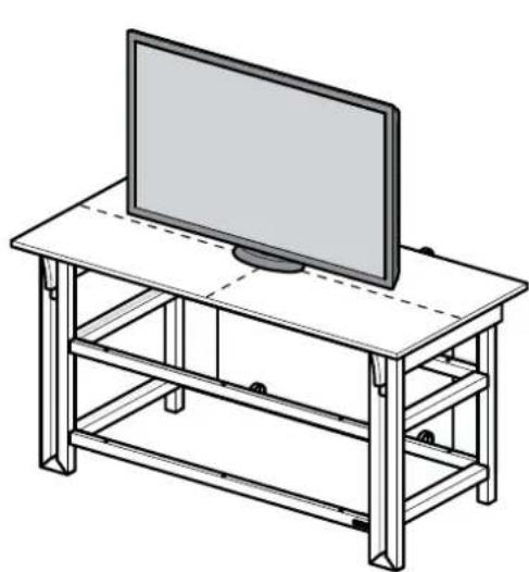
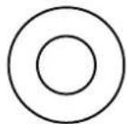
CAUTION: This product is designed for use with flat panel TV's ONLY.
To prevent tipping, be sure to center your fl at panel TV (NO CRT's) on the top of your furniture.
natural_image
Line drawing of a flat-screen TV setup with a monitor on top, supported by metal frame (no text or symbols)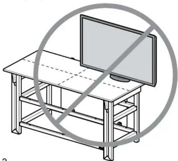
natural_image
Line drawing of a wooden table with a monitor and a circular prohibition symbol (no text or symbols present)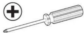
natural_image
Technical line drawing of a metal beam with four circular cutouts (no text or symbols)Supplied Parts and Hardware
⚠ WARNING: This product contains small items that could be a choking hazard if swallowed.
Before starting assembly, verify all parts are included and undamaged. If any parts are missing or damaged, do not return the damaged item to your dealer; contact Customer Service. Never use damaged parts!
Table Parts and Hardware
natural_image
Technical line drawing of a metal frame structure with two vertical supports and horizontal grooves (no text or symbols)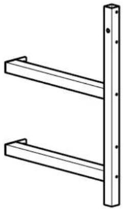
natural_image
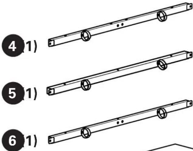
Simple line drawing of two parallel metal beams with mounting holes (no text or symbols)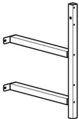
natural_image
Technical line drawing of two parallel metal beams with mounting holes (no text or symbols)
natural_image
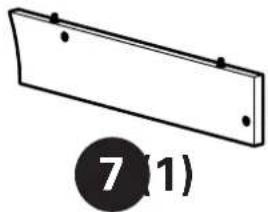
Simple line drawing of a rectangular plate with two holes and a numbered label (7,1) below it.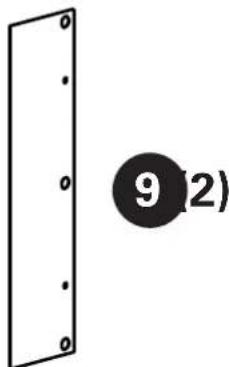
natural_image
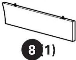
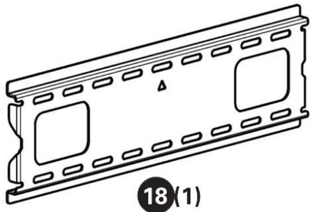
Simple 3D diagram of a rectangular object with a circular label containing the number 8 (1), no text or symbols present.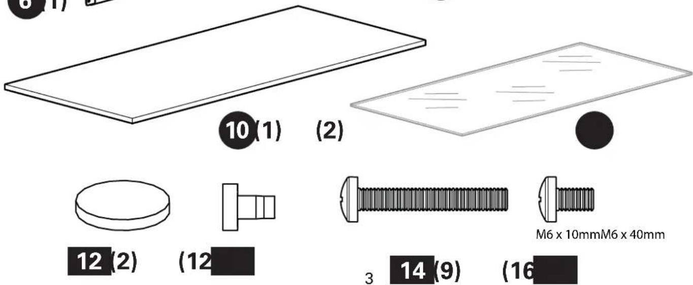
natural_image
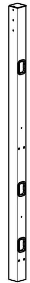
Pure diagram of a vertical rectangular structure with four circular cutouts, no text or symbols present.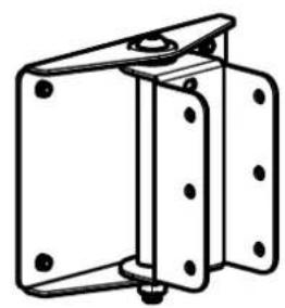
natural_image
Technical line drawing of a mechanical bracket or mounting frame (no text or symbols)17(1)
natural_image
Technical line drawing of a rectangular electronic component with internal slots and mounting holes (no text or symbols)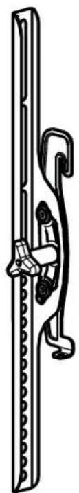
natural_image
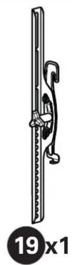
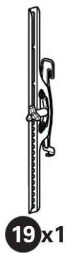
Line drawing of a mechanical latch or clamp mechanism (no text or symbols)19(1)
natural_image
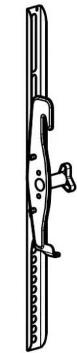
Technical line drawing of a mechanical clamp or bracket (no text or symbols)20(1)
16(1)
natural_image
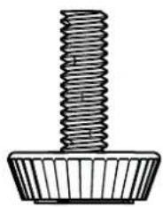
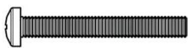
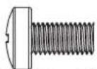
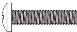
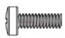
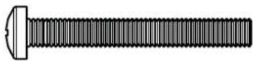
Technical line drawing of a threaded fastener or screw component (no text or symbols)21 (1)
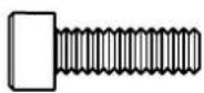
M5 x 16mm
22 (4)
23 (4)
natural_image
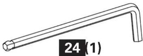
Line drawing of a right-angle wrench with a labeled end (no text or symbols on the tool itself)
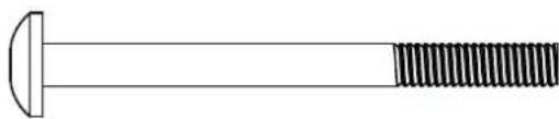
natural_image
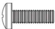
Simple line drawing of a bolt with a flanged end and threaded shaft (no text or symbols)1/4-20 x 2 1/2 in.M5 x 40mm1/4-20 x 3/8 in.M
25
(2)
26
(6)
27
(2)
28
(4)
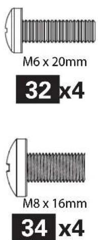
TV Mounting Hardware
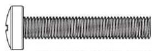
M4 x 35mm M4 x 12mm M6 x 35mm M6 x 12mm M6 x 20mm
29 (4)
30 (4)
31 (4)
32 (4)
33 (4)
M8 x 16mm M8 x 35mm
natural_image
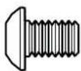
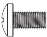
Close-up illustration of a threaded bolt with a flanged head (no text or symbols)34 (4)
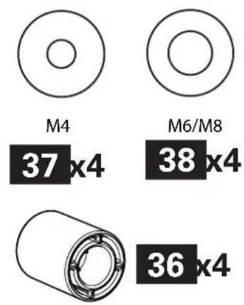
(4)
36 (4)

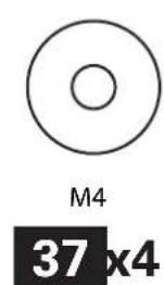
M4
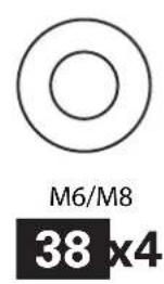
M6/M8
37 (4)

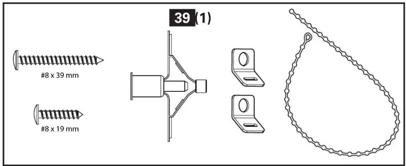
Anti-tip Restraint Kit
natural_image
Simple line drawing of a circular mechanical component with a small hole, no text or symbols present.40 (6)
natural_image
Simple line drawing of a circular mechanical component with a notch (no text or symbols)41 (2)
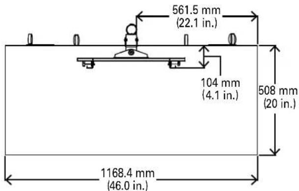
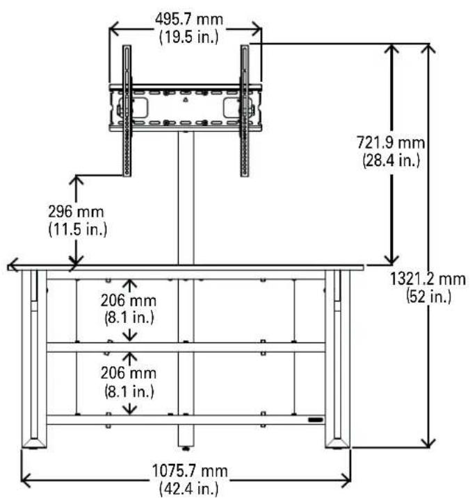
Dimensions
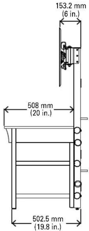
Wall Mounting

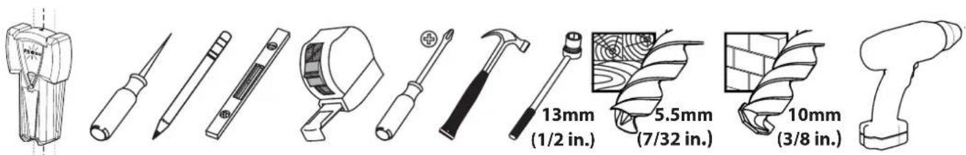
Required Tools
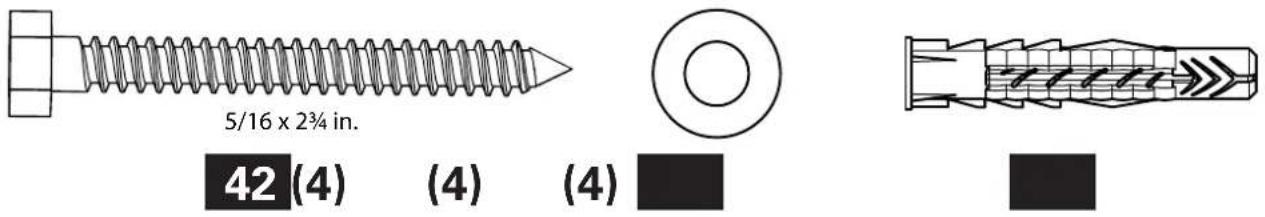
Supplied Parts and Hardware
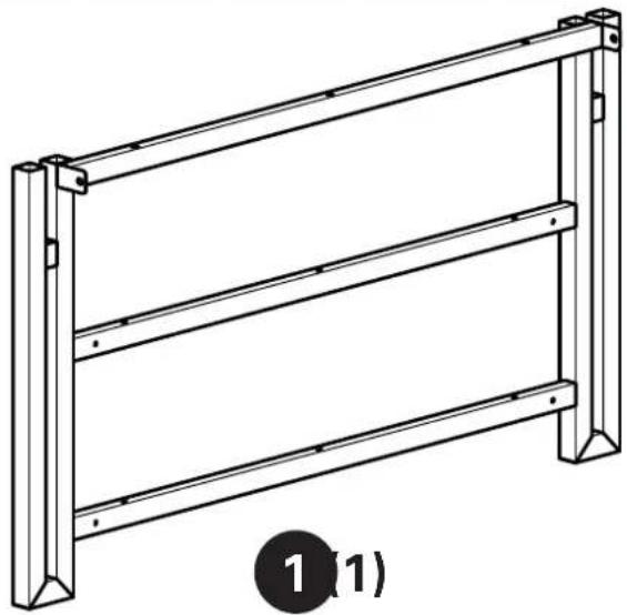
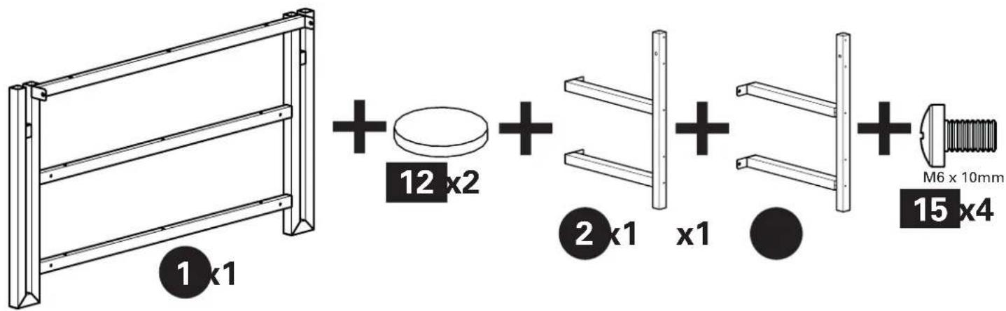
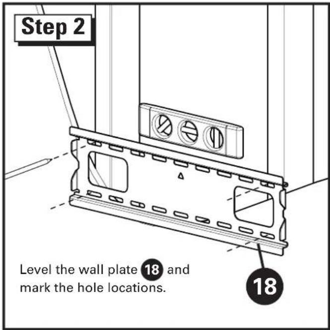
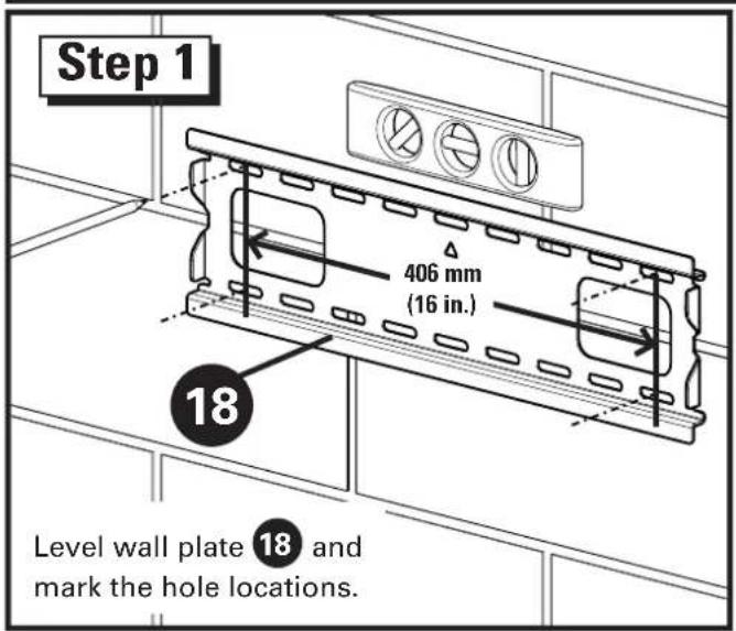
Step 1
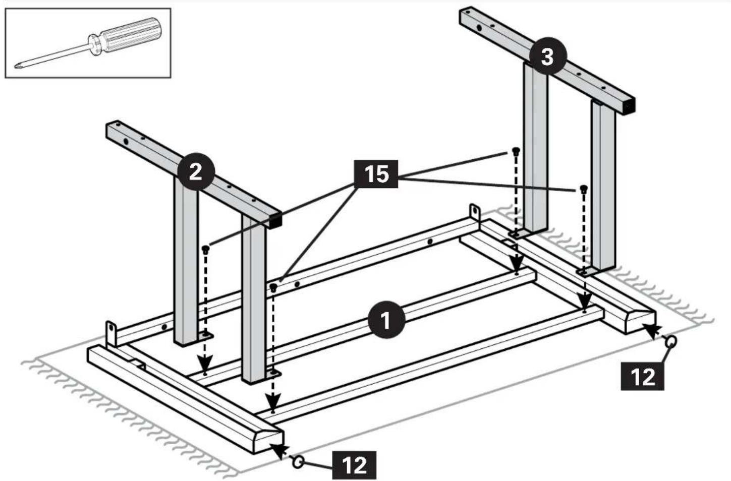
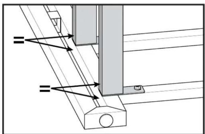
natural_image
Technical diagram of a mechanical assembly with no visible text or symbols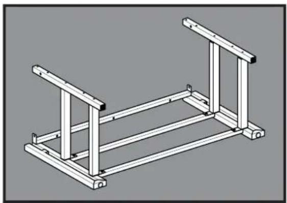
natural_image
Isometric line drawing of a structural frame with two vertical supports and horizontal beams (no text or symbols)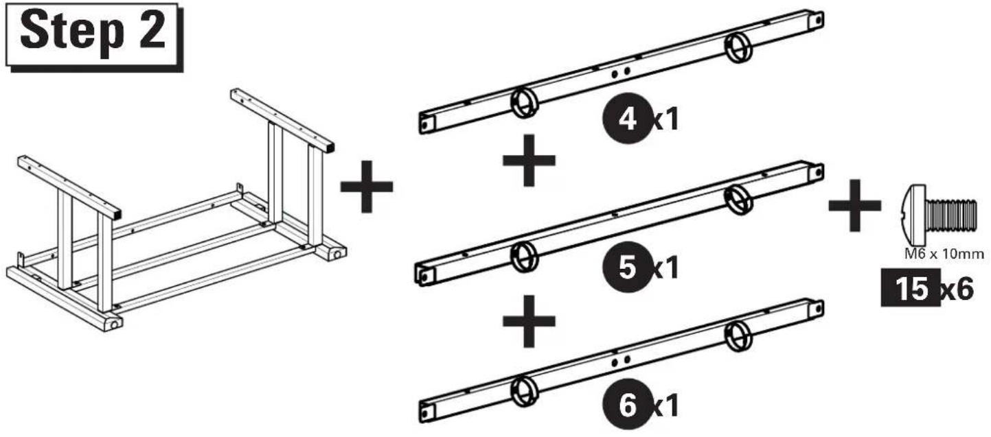
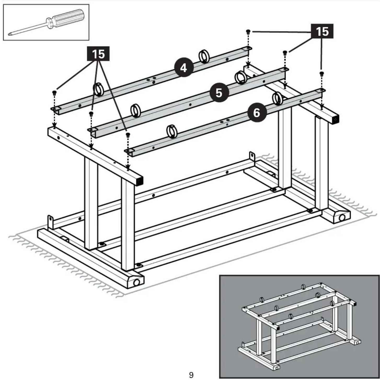
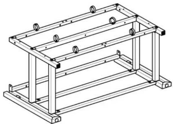
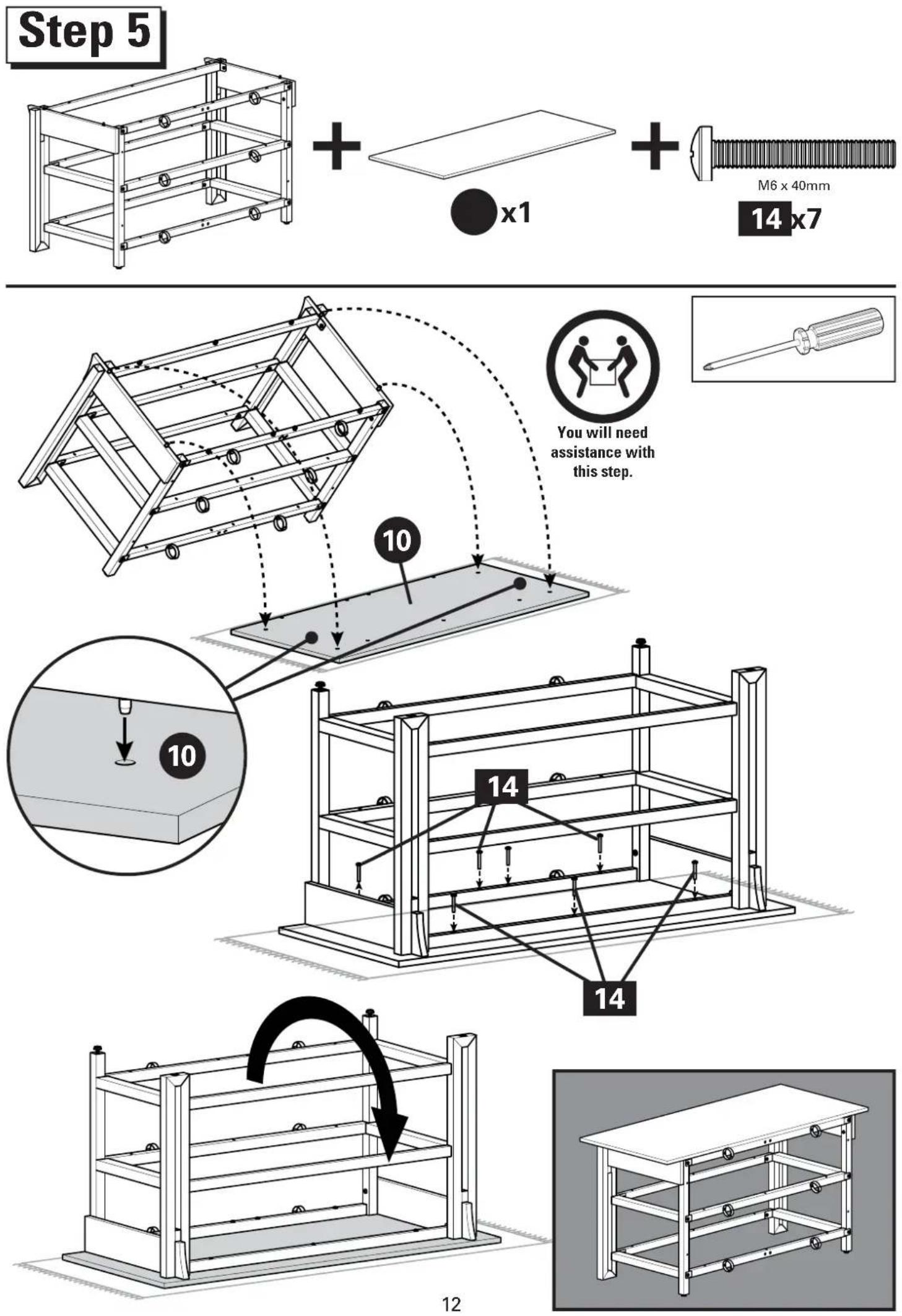
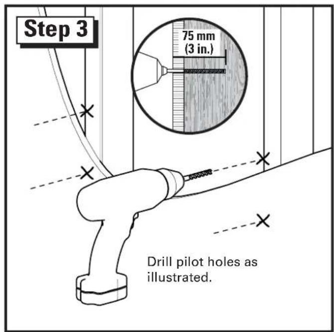
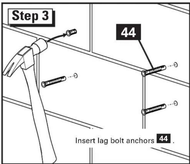
Step 3
natural_image
Technical line drawing of a metal frame structure with mounting holes and supports (no text or symbols)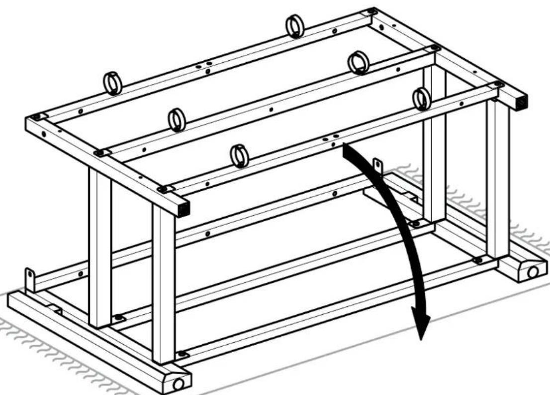
natural_image
Technical line drawing of a mechanical frame structure with mounting holes and a curved arrow indicating force or motion (no text or symbols)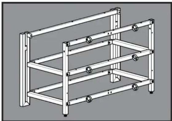
natural_image
Technical line drawing of a multi-level metal shelving unit with bolts and mounting brackets (no text or symbols)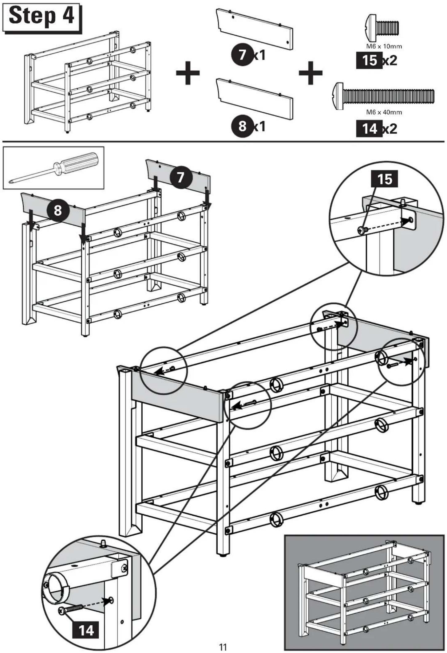
Step 7
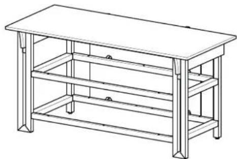
natural_image
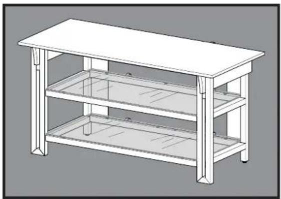
Line drawing of a three-tiered metal bench table with no text or symbols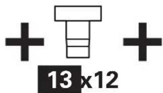
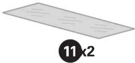
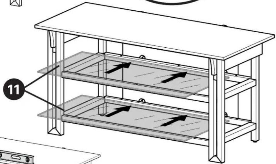
natural_image
Simple diagram of a rectangular plate with diagonal lines and a circular label containing the number 11×2 (no text or symbols on the plate itself)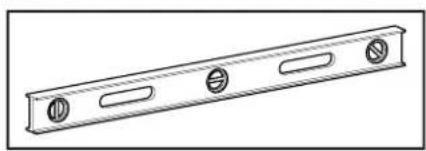
natural_image
Technical line drawing of a metal beam with four circular holes (no text or symbols)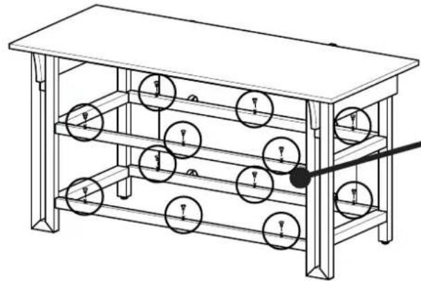
natural_image
Technical line drawing of a multi-tiered mechanical or electrical device with circular components and a pointer (no text or symbols)
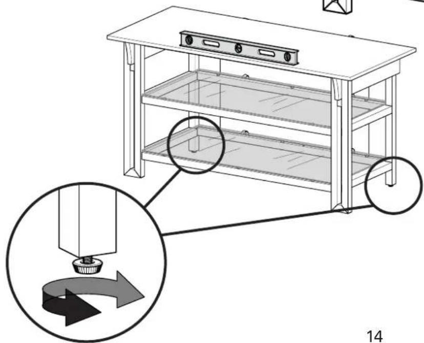
natural_image
Line drawing of a two-tiered office table with a flat top and two lower shelves (no text or symbols)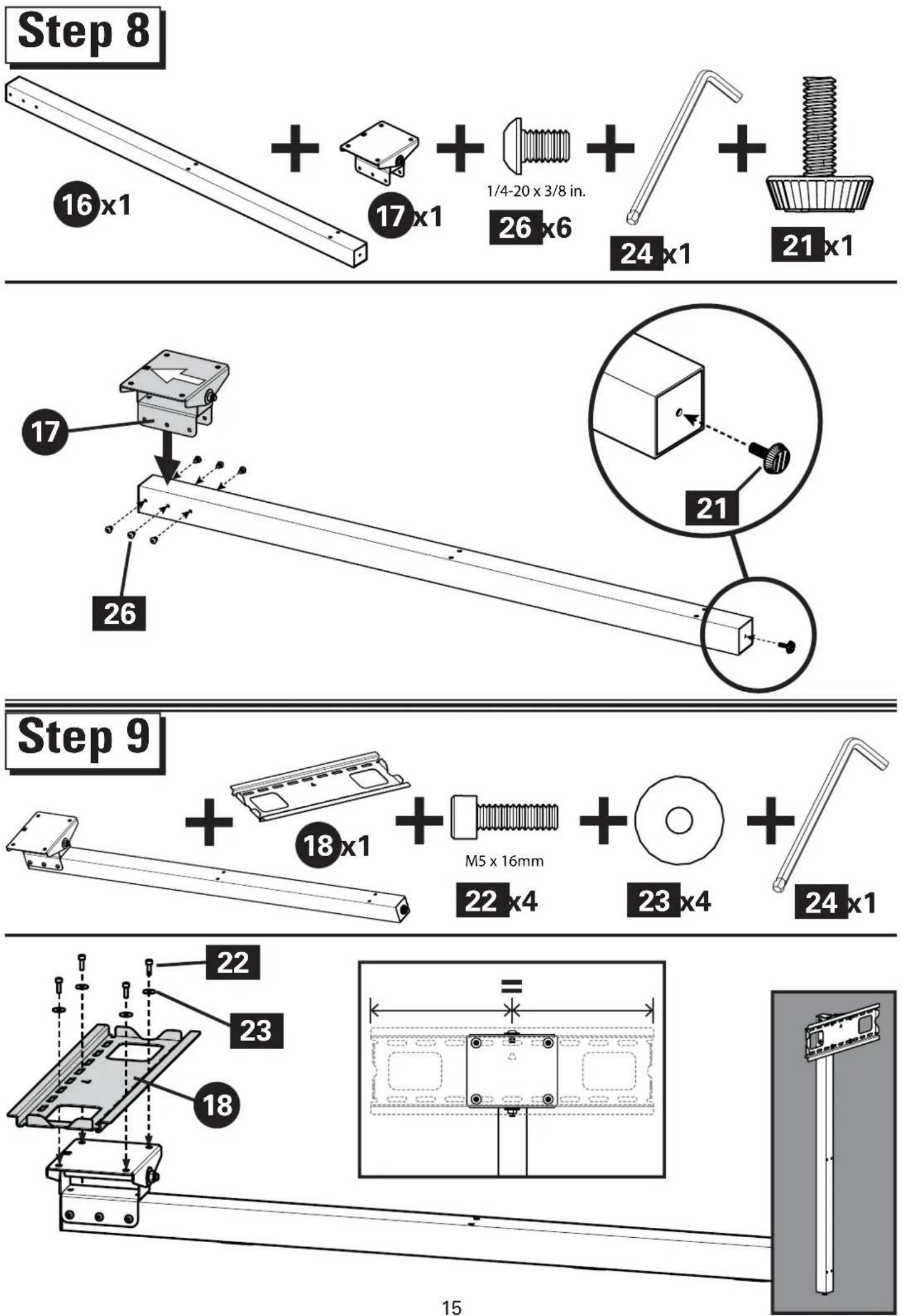
Select TV Hardware
M4 x 35mmM4 x 12mm
M6 x 35mm M6 x 12mm M6 x 20m


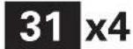


M8 x 16mm M8 x 35mm
natural_image
Technical illustration of a bolt with threaded shaft and flange (no text or symbols)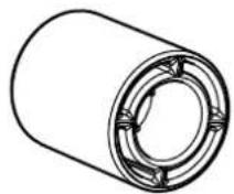
M4

x4


M6/M8

natural_image
Illustration of a mechanical scale with a loop handle and a circular label showing '19 x 1' (no text or symbols on the diagram itself)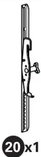
natural_image
Technical line drawing of a mechanical component with no visible text or symbols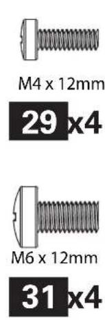
natural_image
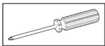
Line drawing of a screwdriver with a pointed tip (no text or symbols)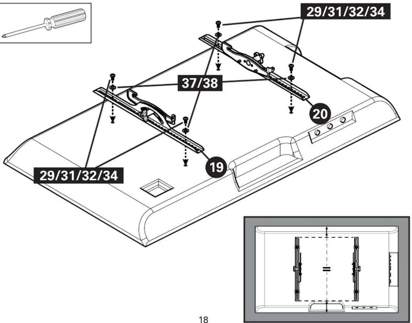
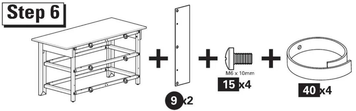
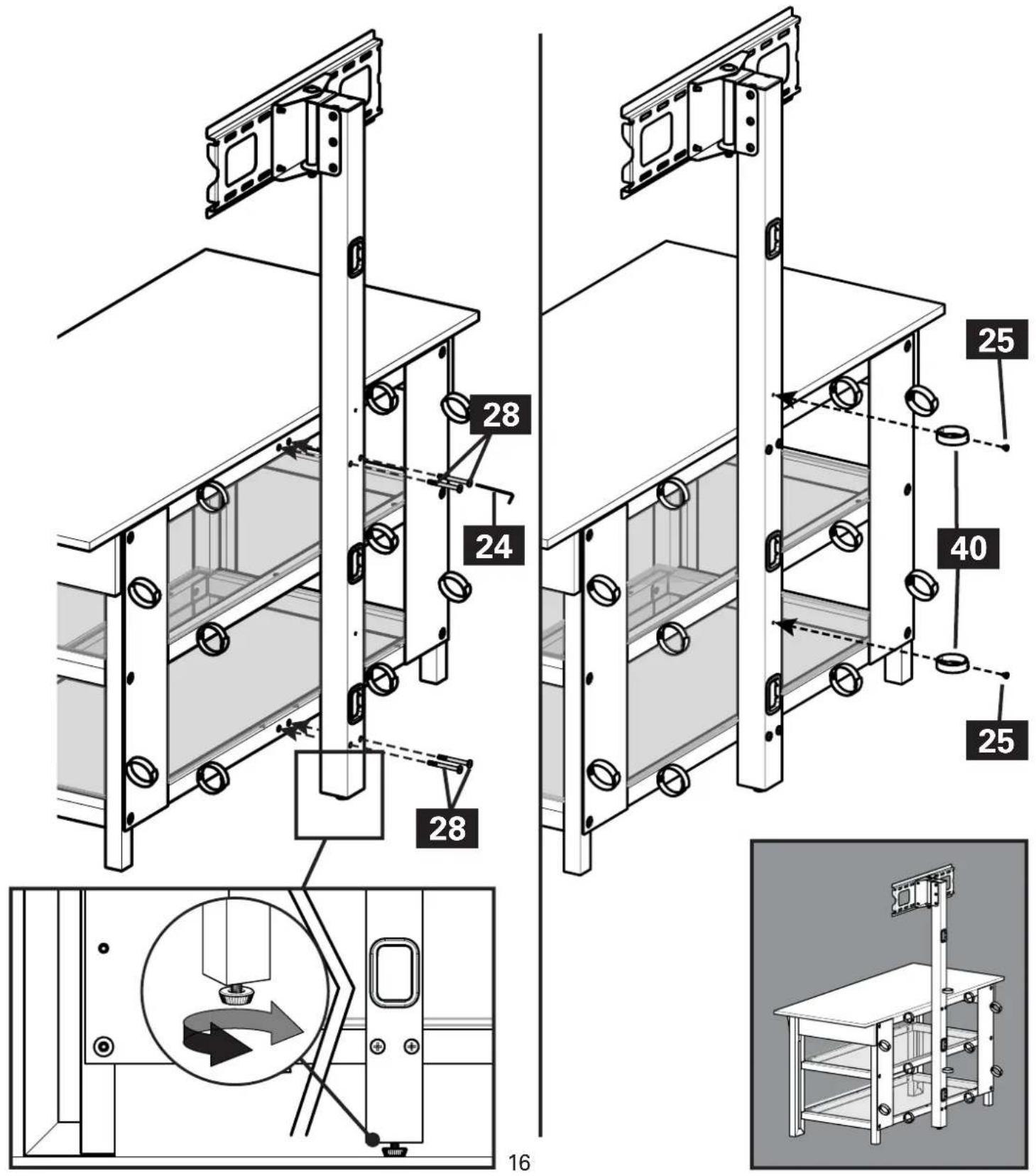
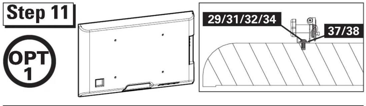
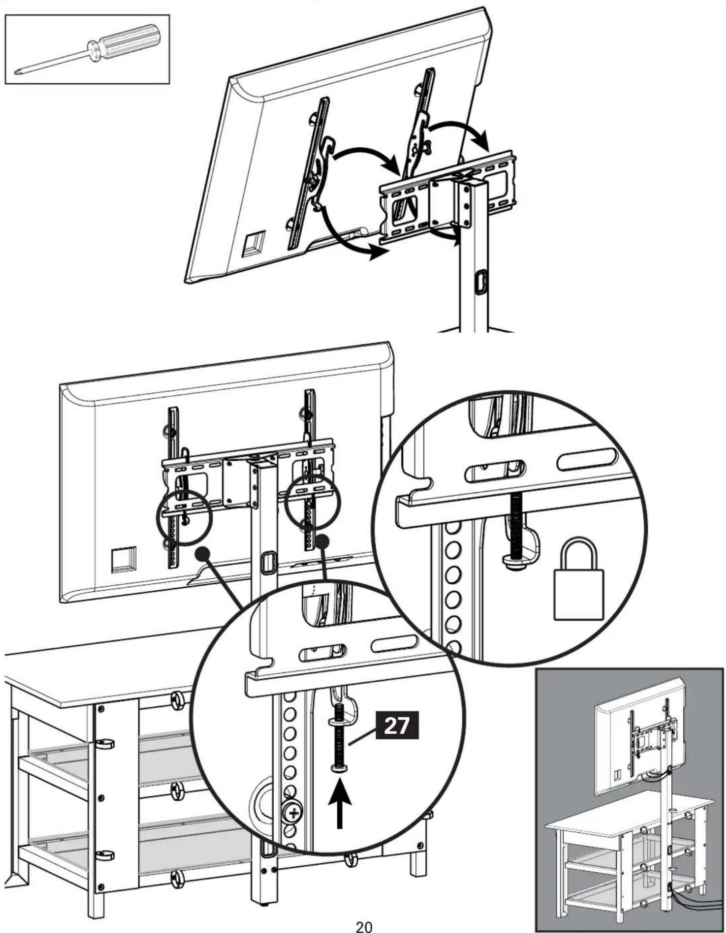
Step 11

natural_image
Line drawing of a rectangular electronic device with four circular holes on its surface (no text or symbols)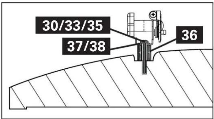
natural_image
Illustration of a mechanical device with a curved handle and circular base, labeled '19 x 1' below (no text or symbols on the device itself)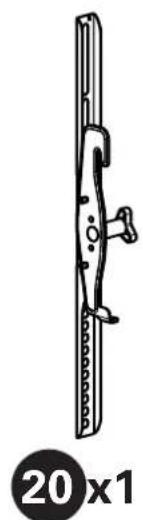
natural_image
Technical line drawing of a mechanical component with a 20x1 ratio label (no text or symbols on the diagram itself)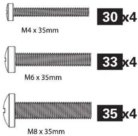
natural_image
Line drawing of a screwdriver with a flat blade and threaded shaft (no text or symbols)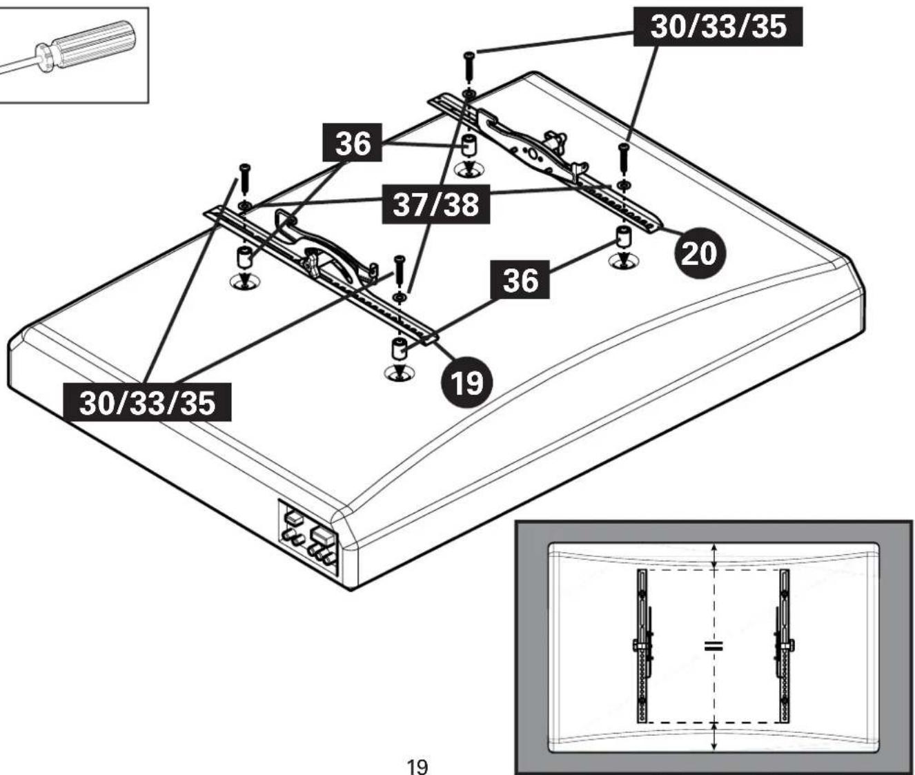
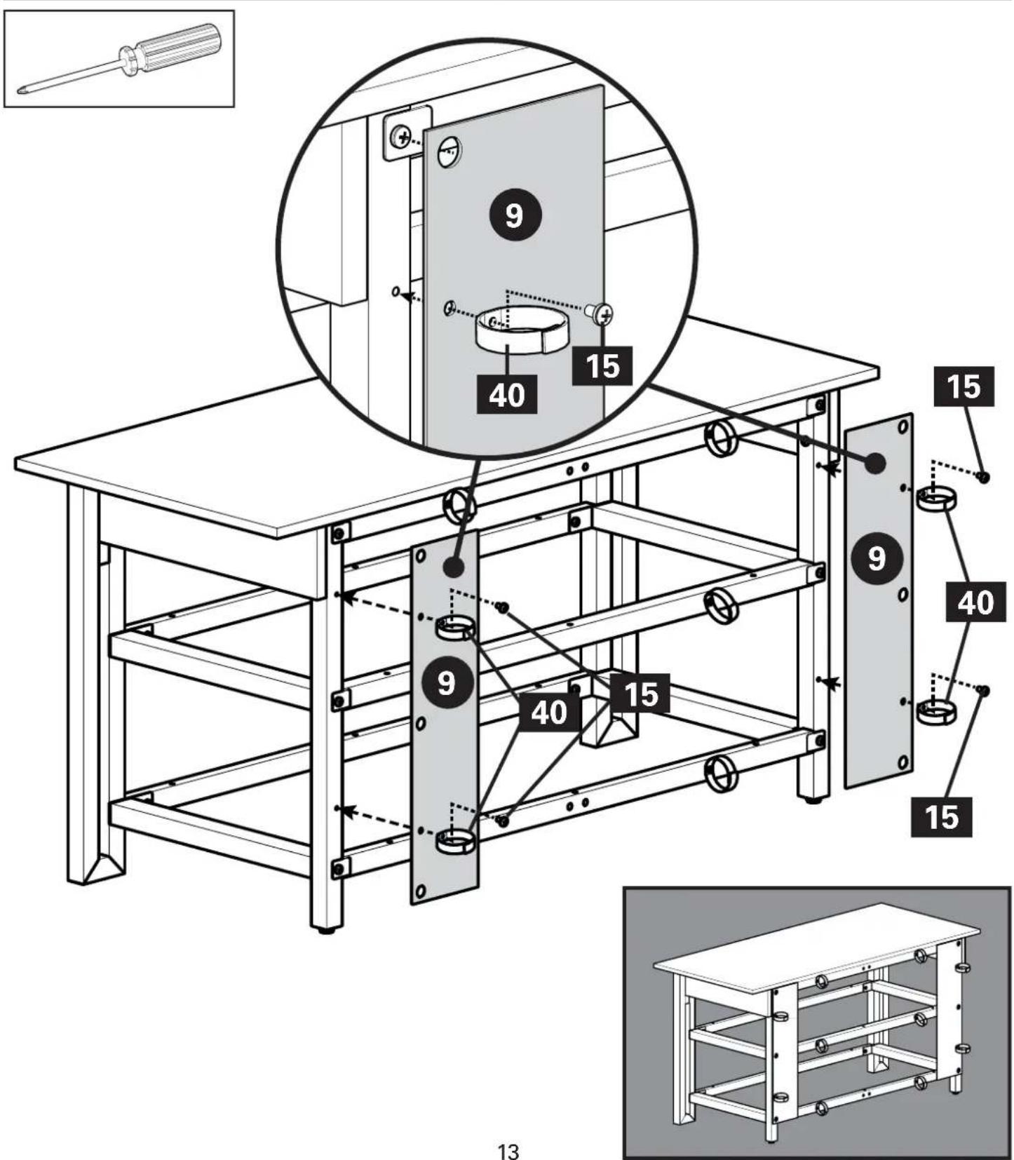
Step 12
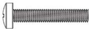
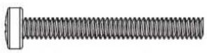
M5 x 40mm
27 x2
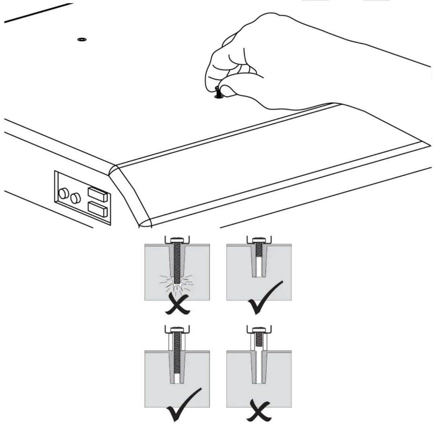
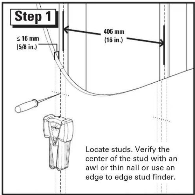
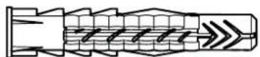
Wood Stud Wall Mounting

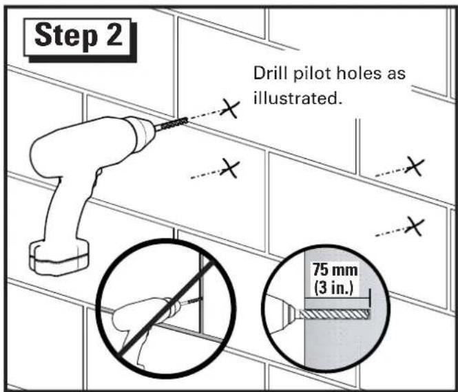
▲ CAUTION: Improper use could reduce the holding power of the lag bolt. To avoid potential injuries or property damage:
- Pilot holes MUST be drilled to a depth of 75 mm (3 in.), using a 5.5 mm (7/32 in.) diameter drill bit.
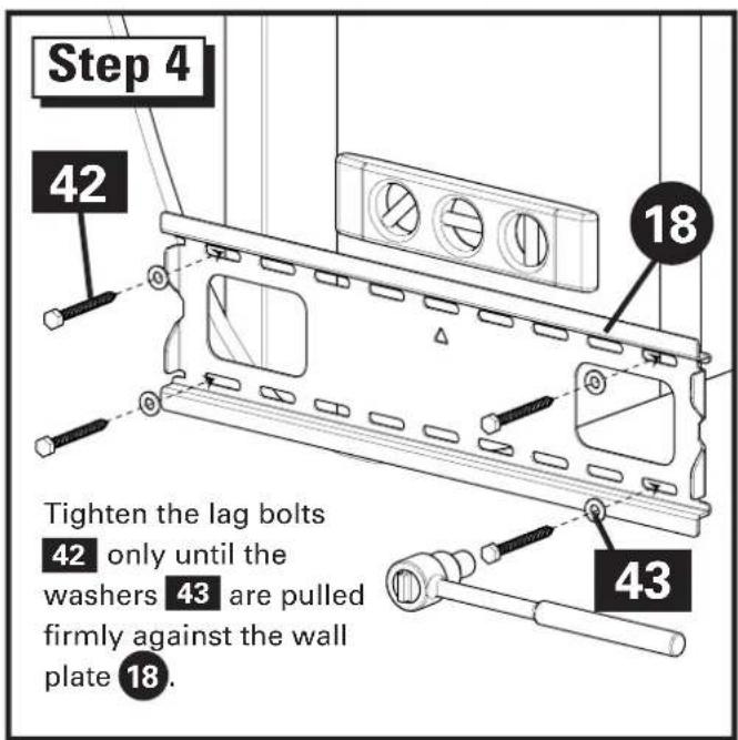
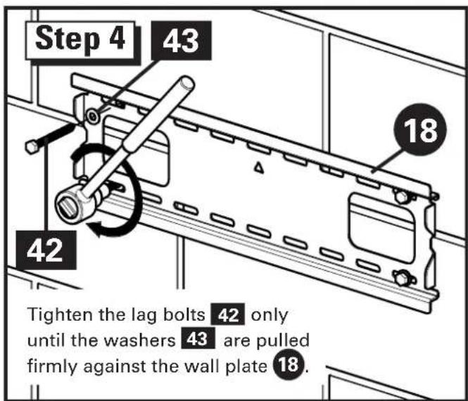
DO NOT over-tighten the lag bo 42.
Any material covering the wall must not exceed 16 mm (5/8 in.).
Minimum wood stud size: common 2 x 4 in. (nominal 1½ x 3½ in.).
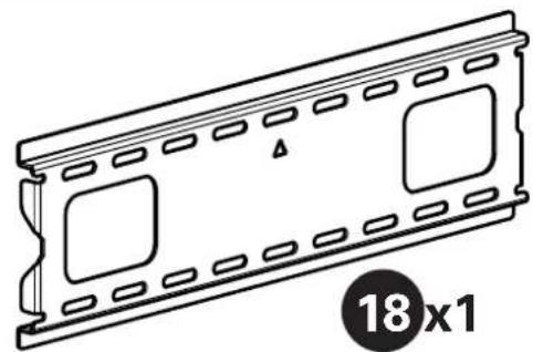
natural_image
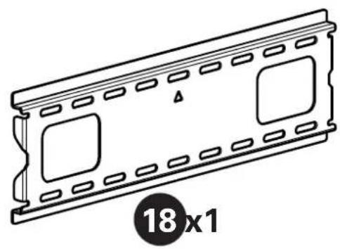
Line drawing of a 18x1 plastic film strip with square cutouts and mounting holes (no text or symbols)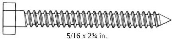
42 x4
43 x4
Solid Concrete and Concrete Block Wall Mounting

▲ CAUTION: Improper use could reduce the holding power of the lag bolt. To avoid potential injuries or property damage:
- Pilot holes MUST be drilled to a depth of 75 mm (3 in.), using a 10 mm (3/8 in.) diameter drill bit.
Be sure the ancho 44 seat flush with the concrete surface.
- Mount wall plate directly onto the concrete surface.
* Never drill into the mortar between blocks.
DO NOT over-tighten the lag bo 42
Minimum solid concrete thickness: 8 in.
Minimum concrete block size: 8 x 8 x 16 in.
Minimum horizontal space between fasteners: 406 mm (16 in.)
natural_image
Technical line drawing of a 18x1 mechanical component with mounting holes and internal slots (no text or symbols)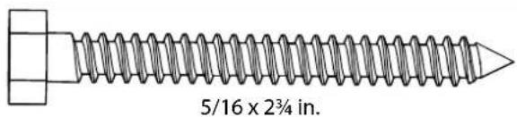
43 x4
42 x4
44 x4
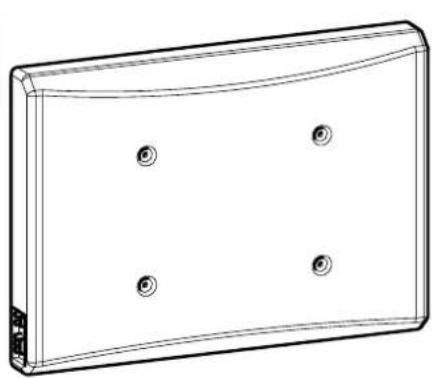
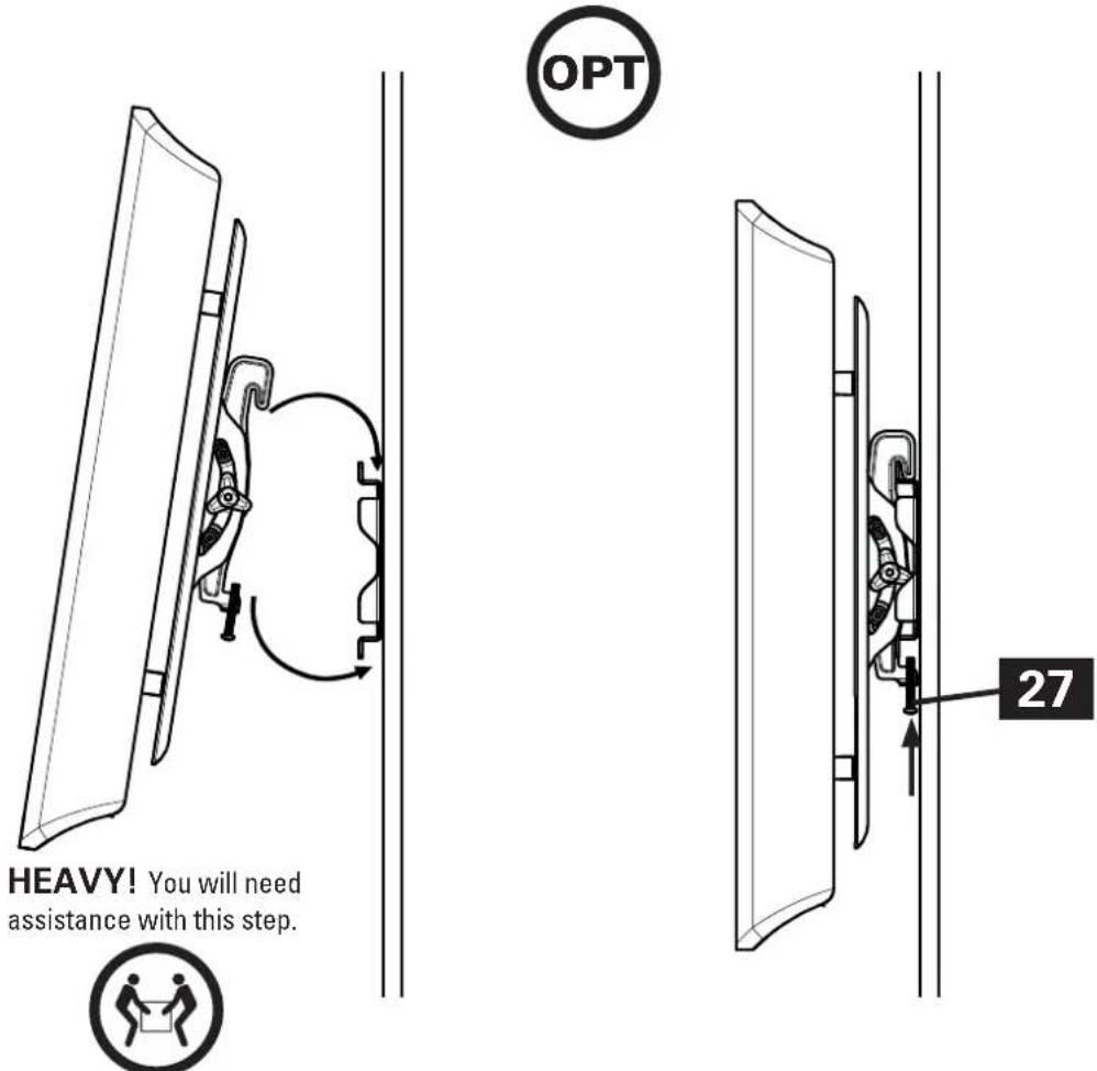
Hang the TV with Mounting Brackets onto the Wall Plate
ESPANOL
natural_image
Two technical illustrations of a flat-screen monitor setup, one with a blank screen and the other with a circular diagram showing a monitor (no text or symbols present)natural_image
Two technical illustrations of a flat-screen TV setup with a monitor on top, shown with a magnified circle highlighting the absence of any text or symbols.©2013 Milestone AV Technologies, a Duchossois Group Company. All rights reserved. Sanus is a division of Milestone. All other brand names or marks are used for identification purposes and are trademarks of their respective owners.
Milestone AV Technologies and its affiliated corporations and subsidiaries (collectively, "Milestone"), intend to make this manual accurate and complete. However, Milestone makes no claim that the information contained herein covers all details, conditions, or variations. Nor does it provide for every possible contingency in connection with the installation or use of this product. The information contained in this document is subject to change without notice or obligation of any kind. Milestone makes no representation of warranty, expressed or implied, regarding the information contained herein. Milestone assumes no responsibility for accuracy, completeness or sufficiency of the information contained in this document.
SANUS • 6436 City West Parkway • Eden Prairie, MN 55344 USA