
US053D - Irrigation timer MAKITA - Free user manual and instructions
Find the device manual for free US053D MAKITA in PDF.

| Product Type | Cordless Garden Sprayer |
| Brand | Makita |
| Model | US053D |
| Rated Voltage | 10.8 V to 12 V max DC |
| Tank Capacity | 5 L |
| Hose Length | 1.7 m |
| Total Extendable Length | 50 - 70 cm |
| Nozzle Type | 2 heads (switchable to 1 head) |
| Max. Working Pressure | 0.3 MPa |
| Pressure with standard nozzle (max.) | Approx. 0.26 MPa |
| Pressure with standard nozzle (min.) | Approx. 0.13 MPa |
| Flow rate with standard nozzle (max.) | Approx. 0.91 L/min |
| Flow rate with standard nozzle (min.) | Approx. 0.47 L/min |
| Nozzle connection thread | G 1/4" |
| Dimensions (L × W × H) | 343 × 182 × 343 mm |
| Net weight | 2.9 - 3.0 kg |
| Power source | Makita lithium-ion battery (10.8 V - 12 V max) |
| Compatible battery cartridges | BL1015 / BL1016 / BL1020B / BL1021B / BL1040B / BL1041B |
| Compatible chargers | DC10SA / DC10SB / DC10WC / DC10WD / DC18RE |
| Main functions | Adjustable spray (mist/jet), lock for continuous spraying, battery indicator, overload protection |
| Maintenance and cleaning | Rinse the tank with clean water after each use; clean the nozzle with a wire; drain and dry before storage |
| Safety | Wear safety glasses, gloves, mask; do not spray flammable liquids; do not use in rain |
| Spare parts and repairability | Use only genuine Makita parts; repairs by authorized center |
| General information | Intended use: spraying consumer-grade chemicals (herbicides, insecticides, fertilizers); do not use for hot or corrosive liquids |
Frequently Asked Questions - US053D MAKITA
User questions about US053D MAKITA
0 question about this device. Answer the ones you know or ask your own.
Ask a new question about this device
Download the instructions for your Irrigation timer in PDF format for free! Find your manual US053D - MAKITA and take your electronic device back in hand. On this page are published all the documents necessary for the use of your device. US053D by MAKITA.
USER MANUAL US053D MAKITA
English (Original instructions)
| 1 | Head switch cock 2 Extension nut 3 Handle 4 Measuring cup | ||||
| 5 | Spray wand bracket 6 Shoulder strap 7 Battery cover 8 Adjustable spray head | ||||
| 9 | Spray wand 10 Lever 11 Hose 12 5L tank | ||||
| 13 | Indicator lamps 14 On/off switch 15 Spray wand holder 16 Locking lever | ||||
| 17 | Hook (for attaching the spray wand) | - | - | - | - |
SPECIFICATIONS
| Model US053D | ||
| Rated voltage D.C. 10.8 V - 12 V max | ||
| Tank capacity 5 L | ||
| Hose length 1.7 m | ||
| Total extendable length 50 - 70 cm | ||
| Nozzle type 2-Head (Switchable to 1 head) | ||
| Max. working pressure 0.3 MPa | ||
| Working pressure with standard nozzle | Max. Approx. 0.26 Mpa | |
| Min. Approx. 0.13 Mpa | ||
| Flow rate with standard nozzle | Max. Approx. 0.91 L/min | |
| Min. Approx. 0.47 L/min | ||
| Nozzle fitting screw G 1/4" | ||
| Dimensions (L × W × H) 343 × 182 × 343 mm | ||
| Net weight 2.9 - 3.0 kg | ||
- Due to our continuing program of research and development, the specifications herein are subject to change without notice.
- Specifications may differ from country to country.
- The weight may differ depending on the attachment(s), including the battery cartridge. The lightest and heaviest combination, according to EPTA-Procedure 01/2014, are shown in the table.
Applicable battery cartridge and charger
| Battery cartridge | BL1015 / BL1016 / BL1020B / BL1021B / BL1040B / BL1041B |
| Charger | DC10SA / DC10SB / DC10WC / DC10WD / DC18RE |
- Some of the battery cartridges and chargers listed above may not be available depending on your region of residence.
WARNING: Only use the battery cartridges and chargers listed above. Use of any other battery cartridges and chargers may cause injury and/or fire.
WARNING: Do not use a corded power supply such as battery adapter or portable power pack with this machine. The cable of such power supply may hinder the operation and result in personal injury.
Symbols
The followings are symbols used for the equipment. Be sure that you understand their meaning before use.
 | Wear ear protection. |  | Warning |
 | Wear a breathing mask. |  | Wear eye protection. |
 | Wear safety footwear. |  | Wear protective gloves. |
 | Do not use in the rain or leave the sprayer outdoors while raining. | ||
 | Read instruction manual. | ||
 | Keep bystanders away when spraying. | ||
Intended use
This machine is intended for spraying.
Noise
The typical A-weighted noise level determined according to EN62841-1:
Sound pressure level ( L_pA ): 70 dB(A) or less
Uncertainty (K): 3 dB(A)
NOTE: The declared noise emission value(s) has been measured in accordance with a standard test method and may be used for comparing one tool with another.
NOTE: The declared noise emission value(s) may also be used in a preliminary assessment of exposure.

WARNING: Wear ear protection.

WARNING: The noise emission during actual time of the power tool can differ from the declared value(s) depending on the ways in which the tool is used especially what kind of workpiece is processed.

WARNING: Be sure to identify safety measures to protect the operator that are based on animation of exposure in the actual conditions of the (taking account of all parts of the operating cycle such as the times when the tool is switched and when it is running idle in addition to the longer time).
Vibration
The vibration total value (tri-axial vector sum) determined according to EN62841-1:
Work mode: operation without load
Vibration emission (ah): 2.5 m/s ^2 or less
Uncertainty (K) : 1.5 m/s²
NOTE: The declared vibration total value(s) has been measured in accordance with a standard test method and may be used for comparing one tool with another.
NOTE: The declared vibration total value(s) may also be used in a preliminary assessment of exposure.

WARNING: The vibration emission during dual use of the power tool can differ from the declared value(s) depending on the ways in which a tool is used especially what kind of workpiece processed.

WARNING: Be sure to identify safety measures to protect the operator that are based on animation of exposure in the actual conditions of the (taking account of all parts of the operating cycle such as the times when the tool is switched and when it is running idle in addition to the longer time).
EC Declaration of Conformity
For European countries only
The EC declaration of conformity is included as Annex A to this instruction manual.
WARNING
This appliance can be used by children aged from 8 years and above and persons with reduced physical, sensory or mental capa-bilities or lack of experience and knowledge if they have been given supervision or instruction concerning use of the appliance in a safe way and understand the hazards involved. Children shall not play with the appliance. Cleaning and user maintenance shall not be made by children without supervision.
General power tool safety warnings

WARNING: Read all safety warnings, instructions, illustrations and specifications provided with this power tool. Failure to follow all instructions led below may result in electric shock, fire and/orious injury.
Save all warnings and instructions for future reference.
The term “power tool” in the warnings refers to your mains-operated (corded) power tool or battery-operated (cordless) power tool.
Work area safety
- Keep work area clean and well lit. Cluttered or dark areas invite accidents.
- Do not operate power tools in explosive atmospheres, such as in the presence of flammable liquids, gases or dust. Power tools create sparks which may ignite the dust or fumes.
- Keep children and bystanders away while operating a power tool. Distractions can cause you to lose control.
Electrical safety
- Power tool plugs must match the outlet. Never modify the plug in any way. Do not use any adapter plugs with earthed (grounded) power tools. Unmodified plugs and matching outlets will reduce risk of electric shock.
- Avoid body contact with earthed or grounded surfaces, such as pipes, radiators, ranges and refrigerators. There is an increased risk of electric shock if your body is earthed or grounded.
- Do not expose power tools to rain or wet conditions. Water entering a power tool will increase the risk of electric shock.
- Do not abuse the cord. Never use the cord for carrying, pulling or unplugging the power tool. Keep cord away from heat, oil, sharp edges or moving parts. Damaged or entangled cords increase the risk of electric shock.
- When operating a power tool outdoors, use an extension cord suitable for outdoor use. Use of a cord suitable for outdoor use reduces the risk of electric shock.
- If operating a power tool in a damp location is unavoidable, use a residual current device (RCD) protected supply. Use of an RCD reduces the risk of electric shock.
- Power tools can produce electromagnetic fields (EMF) that are not harmful to the user. However, users of pacemakers and other similar medical devices should contact the maker of their device and/or doctor for advice before operating this power tool.
Personal safety
- Stay alert, watch what you are doing and use common sense when operating a power tool. Do not use a power tool while you are tired or under the influence of drugs, alcohol or medication. A moment of inattention while operating power tools may result in serious personal injury.
- Use personal protective equipment. Always wear eye protection. Protective equipment such as a dust mask, non-skid safety shoes, hard hat or hearing protection used for appropriate conditions will reduce personal injuries.
- Prevent unintentional starting. Ensure the switch is in the off-position before connecting to power source and/or battery pack, picking up or carrying the tool. Carrying power tools with your finger on the switch or energising power tools that have the switch on invites accidents.
- Remove any adjusting key or wrench before turning the power tool on. A wrench or a key left attached to a rotating part of the power tool may result in personal injury.
-
Do not overreach. Keep proper footing and balance at all times. This enables better control of the power tool in unexpected situations.
-
Dress properly. Do not wear loose clothing or jewellery. Keep your hair and clothing away from moving parts. Loose clothes, jewellery or long hair can be caught in moving parts.
- If devices are provided for the connection of dust extraction and collection facilities, ensure these are connected and properly used. Use of dust collection can reduce dust-related hazards.
- Do not let familiarity gained from frequent use of tools allow you to become complacent and ignore tool safety principles. A careless action can cause severe injury within a fraction of a second.
- Always wear protective goggles to protect your eyes from injury when using power tools. The goggles must comply with ANSI Z87.1 in the USA, EN 166 in Europe, or AS/NZS 1336 in Australia/New Zealand. In Australia/New Zealand, it is legally required to wear a face shield to protect your face, too.
natural_image
Line drawing of a person wearing a hard hat and safety goggles (no text or symbols)It is an employer's responsibility to enforce the use of appropriate safety protective equipments by the tool operators and by other persons in the immediate working area.
Power tool use and care
- Do not force the power tool. Use the correct power tool for your application. The correct power tool will do the job better and safer at the rate for which it was designed.
- Do not use the power tool if the switch does not turn it on and off. Any power tool that cannot be controlled with the switch is dangerous and must be repaired.
- Disconnect the plug from the power source and/or remove the battery pack, if detachable, from the power tool before making any adjustments, changing accessories, or storing power tools. Such preventive safety measures reduce the risk of starting the power tool accidentally.
-
Store idle power tools out of the reach of children and do not allow persons unfamiliar with the power tool or these instructions to operate the power tool. Power tools are dangerous in the hands of untrained users.
-
Maintain power tools and accessories. Check for misalignment or binding of moving parts, breakage of parts and any other condition that may affect the power tool's operation. If damaged, have the power tool repaired before use. Many accidents are caused by poorly maintained power tools.
- Keep cutting tools sharp and clean. Properly maintained cutting tools with sharp cutting edges are less likely to bind and are easier to control.
- Use the power tool, accessories and tool bits etc. in accordance with these instructions, taking into account the working conditions and the work to be performed. Use of the power tool for operations different from those intended could result in a hazardous situation.
- Keep handles and grasping surfaces dry, clean and free from oil and grease. Slippery handles and grasping surfaces do not allow for safe handling and control of the tool in unexpected situations.
- When using the tool, do not wear cloth work gloves which may be entangled. The entanglement of cloth work gloves in the moving parts may result in personal injury.
Battery tool use and care
- Recharge only with the charger specified by the manufacturer. A charger that is suitable for one type of battery pack may create a risk of fire when used with another battery pack.
- Use power tools only with specifically designated battery packs. Use of any other battery packs may create a risk of injury and fire.
- When battery pack is not in use, keep it away from other metal objects, like paper clips, coins, keys, nails, screws or other small metal objects, that can make a connection from one terminal to another. Shorting the battery terminals together may cause burns or a fire.
- Under abusive conditions, liquid may be ejected from the battery; avoid contact. If contact accidentally occurs, flush with water. If liquid contacts eyes, additionally seek medical help. Liquid ejected from the battery may cause irritation or burns.
- Do not use a battery pack or tool that is damaged or modified. Damaged or modified batteries may exhibit unpredictable behaviour resulting in fire, explosion or risk of injury.
- Do not expose a battery pack or tool to fire or excessive temperature. Exposure to fire or temperature above 130 °C may cause explosion.
- Follow all charging instructions and do not charge the battery pack or tool outside the temperature range specified in the instructions.
Charging improperly or at temperatures outside the specified range may damage the battery and increase the risk of fire.
Service
- Have your power tool serviced by a qualified repair person using only identical replacement parts. This will ensure that the safety of the power tool is maintained.
- Never service damaged battery packs. Service of battery packs should only be performed by the manufacturer or authorized service providers.
- Follow instruction for lubricating and changing accessories.
Cordless Garden Sprayer Safety Warnings
WARNING: Risk of fire or explosion. Do not spray flammable liquids such as gasoline. Look for this symbol reference on the container.
WARNING: Some spray created from products used with the sprayer contains chemicals known to cause cancer, birth defect of other reproductive harm.
Some examples of these chemicals are:
compounds in fertilize
compounds in insecticides, herbicides, and pesticides; arsenic and chromium from chemically treated lumber. Follow directions on containers of all such products. To reduce your exposure to these chemicals, wear approved safety equipment such as face masks that are specially designed to filter out sprays, gloves, and other appropriate protective equipment.
■ Before using any pesticide or other spray materials in this sprayer, read the label on its original container thoroughly and follow its directions.
Some spray materials are dangerous and should not be used in this sprayer, as they can damage the sprayer and cause serious bodily injury or property damage.
■ Electric shock hazard. Never spray toward electrical outlets.
■ Do not use commercial grade chemicals or chemicals for commercial or industrial purposes. Use only consumer grade water-based lawn and garden chemicals.
■ Do not pour hot or boiling liquids into the tank. These can weaken or damage the hose or tank.
■ Spray area must be well ventilated.
■ Avoid spraying on windy days. Spray can be accidentally blown onto plants or objects that should not be sprayed.
■ Store the sprayer in a secure, well-ventilated indoor space with the fluid tank empty.
■ Do not use caustic (alkali) self-heating or corrosive (acid) liquids in this sprayer. These can corrode metal parts or weaken the tank and hose.
■ Know the contents of the chemical being sprayed. Read all Material Safety Data Sheets (MSDS) and container labels provided with the chemical. Follow the chemical manufacturer's safety instructions.
■ Do not leave residue or spray material in the tank after using the sprayer. Clean after each use.
■ Do not smoke while using the sprayer, or spray where spark or flame is present.
■ Risk of injection. Do not discharge directly against skin.
■ To reduce the risk of electric shock, do not put the sprayer into water or other liquid. Do not place or store the sprayer where it can fall or be pulled into a tub or sink.
- Maintain this product. Thoroughly inspect both the inside and outside of the sprayer and examine the components before each use. Check for cracked and deteriorated hoses, leaks, clogged nozzles, and missing or damaged parts. If damaged, have the product repaired before use. Many accidents are caused by poorly maintained products.
■ Disconnect the battery from the unit before draining, cleaning, or storing the sprayer. Such preventive safety measures reduce the risk of accidental starting.
■ Always wear eye protection with side shields or goggles marked to comply with ANSI Z87.1. Failure to do so could result in fluids entering your eyes resulting in possible serious injury.
■ Protect your lungs. Wear a face or dust mask when using the sprayer. Following this rule will reduce the risk of serious personal injury.
■ Battery tools do not have to be plugged into an electrical outlet; therefore, they are always in operating condition. Be aware of possible hazards when not using your battery tool or when changing accessories. Remove battery pack when tool is not in use. Following this rule will reduce the risk of electric shock, fire, or serious personal injury.
■ Do not place battery tools or their batteries near fire or heat. This will reduce the risk of explosion and possibly injury.
- Do not crush, drop or damage battery pack. Do not use a battery pack or charger that has been dropped or received a sharp blow. A damaged battery is subject to explosion. Properly dispose of a dropped or damaged battery immediately.
■ Batteries can explode in the presence of a source of ignition, such as a pilot light. To reduce the risk of serious personal injury, never use any cordless product in the presence of open flame. An exploded battery can propel debris and chemicals. If exposed, flush with water immediately.
■ Do not charge battery tool in a damp or wet location. Following this rule will reduce the risk of electric shock.
■ For best results, your battery tool should be charged in a location where the temperature is more than 10 °C (50 °F) but less than 40 °C (104 °F). To reduce the risk of serious personal injury, do not store outside or in vehicles.
■ Under extreme usage or temperature conditions, battery leakage may occur. If liquid comes in contact with your skin, wash immediately with soap and water. If liquid gets into your eyes, flush them with clean water for at least 10 minutes, then seek immediate medical attention. Following this rule will reduce the risk of serious personal injury.
■ Do not use battery-operated appliance in rain.
■ Do not use battery-operated appliance in rain. Exercise care in handling batteries in order not to short the battery with conducting materials such as rings, bracelets, and keys. The battery or conductor may overheat and cause burns.
■ Do not dispose of the battery(ies) in a fire. The cell may explode. Check with local codes for possible special disposal instructions.
■ Do not open or mutilate the battery(ies). Released electrolyte is corrosive and may cause damage to the eyes or skin. It may be toxic if swallowed.
- Avoid Dangerous Environment - Don't use appliances in damp or wet locations.
■ Use Right Appliance - Do not use appliance for any job except that for which it is intended.
- Don’t Force Appliance - It will do the job better and with less likelihood of a risk of injury at the rate for which it was designed.
■ Store Idle Appliances Indoors - When not in use, appliances should be stored indoors in dry, and high or locked-up place - out of reach of children.
- Maintain Appliance With Care - Keep clean for best performance and to reduce the risk of injury. Follow instructions for changing accessories. Inspect appliance cord, and if damaged, have it repaired by an authorized service facility. Keep handles dry, clean, and free from oil and grease.
- Check Damaged Parts - Before further use of the appliance, a guard or other part that is damaged should be carefully checked to determine that it will operate properly and perform its intended function. Check for alignment of moving parts, binding of moving parts, breakage of parts, mounting, and any other condition that may affect its operation. A guard or other part that is damaged should be properly repaired or replaced by an authorized service center unless indicated elsewhere in this manual.
- Don't topple a filled-up tank to avoid leak in case tank cover is not tightened.
Important safety instructions for battery cartridge
- Before using battery cartridge, read all instructions and cautionary markings on (1) battery charger, (2) battery, and (3) product using battery.
- Do not disassemble or tamper the battery cartridge. It may result in a fire, excessive heat, or explosion.
- If operating time has become excessively shorter, stop operating immediately. It may result in a risk of overheating, possible burns and even an explosion.
- If electrolyte gets into your eyes, rinse them out with clear water and seek medical attention right away. It may result in loss of your eyesight.
- Do not short the battery cartridge:
(1) Do not touch the terminals with any conductive material.
(2) Avoid storing battery cartridge in a container with other metal objects such as nails, coins, etc.
(3) Do not expose battery cartridge to water or rain.
A battery short can cause a large current flow, overheating, possible burns and even a breakdown.
- Do not store and use the tool and battery cartridge in locations where the temperature may reach or exceed 50 °C (122 °F).
- Do not incinerate the battery cartridge even if it is severely damaged or is completely worn out. The battery cartridge can explode in a fire.
- Do not nail, cut, crush, throw, drop the battery cartridge, or hit against a hard object to the battery cartridge. Such conduct may result in a fire, excessive heat, or explosion.
- Do not use a damaged battery.
- The contained lithium-ion batteries are subject to the Dangerous Goods Legislation requirements.
For commercial transports e.g. by third parties, forwarding agents, special requirement on packaging and labeling must be observed.
For preparation of the item being shipped, consulting an expert for hazardous material is required.
Please also observe possibly more detailed national regulations.
Tape or mask off open contacts and pack up the battery in such a manner that it cannot move around in the packaging.
- When disposing the battery cartridge, remove it from the tool and dispose of it in a safe place. Follow your local regulations relating to disposal of battery.
- Use the batteries only with the products specified by Makita. Installing the batteries to non-compliant products may result in a fire, excessive heat, explosion, or leak of electrolyte.
- If the tool is not used for a long period of time, the battery must be removed from the tool.
- During and after use, the battery cartridge may take on heat which can cause burns or low temperature burns. Pay attention to the handling of hot battery cartridges.
- Do not touch the terminal of the tool immediately after use as it may get hot enough to cause burns.
- Do not allow chips, dust, or soil stuck into the terminals, holes, and grooves of the battery cartridge. It may result in poor performance or breakdown of the tool or battery cartridge.
- Unless the tool supports the use near high-voltage electrical power lines, do not use the battery cartridge near high-voltage electrical power lines. It may result in a malfunction or breakdown of the tool or battery cartridge.
- Keep the battery away from children.
SAVE THESE INSTRUCTIONS.
CAUTION: Only use genuine Makita batteries. Use of non-genuine Makita batteries, or batteries that have been altered, may result in the battery bursting causing fires, personal injury and damage. It will also void the Makita warranty for the Makita tool and charger.
Tips for maintaining maximum battery life
- Charge the battery cartridge before completely discharged. Always stop tool operation and charge the battery cartridge when you notice less tool power.
- Never recharge a fully charged battery cartridge. Overcharging shortens the battery service life.
- Charge the battery cartridge with room temperature at 10 °C - 40 °C ( 50 °F - 104 °F ). Let a hot battery cartridge cool down before charging it.
- When not using the battery cartridge, remove it from the tool or the charger.
CORDLESS GARDEN SPRAYER USE AND CARE
- The cordless garden sprayer can work by Makita lithium-ion battery cartridge. Use of any other batteries may create a risk of fire. Recharge batteries only with the specified charger. A charger that may be suitable for one type of battery may create a risk of fire when used with another battery.
- When inserting or removing the battery, always place the cordless garden sprayer on a flat and stable surface.
- Do not use any batteries, attachments or accessories not recommended by the manufacturer of this appliance. The use of batteries, attachments or accessories not recommended can result in serious personal injury.
ASSEMBLY

CAUTION:
Always be sure that the machine is switched off and the battery cartridge is removed before carrying out any work on the machine.

CAUTION:
Make sure that the all parts are securely assembled so that the liquid does not leak when operating the machine.
Assembly of the spray wand
- Remove the cap from the handle.
- Make sure the O-ring is in place, then thread the spray wand onto the handle and tighten it securely. Refer to Figure 1.
- Loosen the extension nut and pull out the spray wand to the desire length.
- Retighten the extension nut.
| 1 Adjustable spray head 2 Extension nut | |
| 3 Spray wand 4 O-ring | |
| 5 Handle | |
Figure 1
Shoulder strap
Attach the shoulder strap to the hangers of the machine as shown in the figure. Refer to Figure 2.
Figure 2
FUNCTIONAL DESCRIPTION

CAUTION:
Always be sure that the machine is switched off and the battery cartridge is removed before adjusting or checking function on the machine.
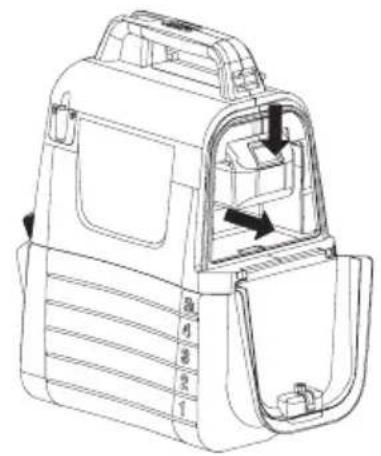
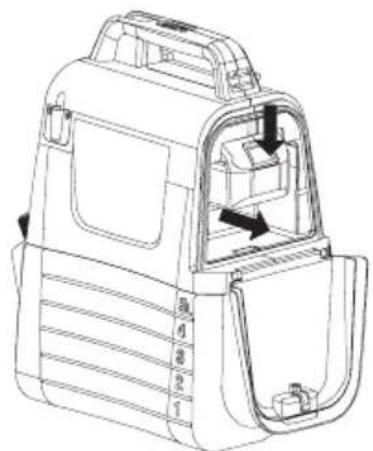
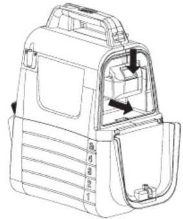
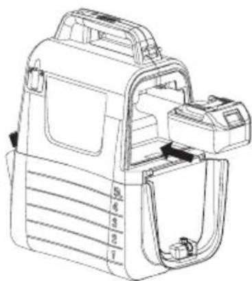
Installing or removing the battery cartridge

CAUTION:
• Always switch off the machine before installing or removing of the battery cartridge.
- Hold the machine and the battery cartridge firmly when installing or removing battery cartridge. Failure to hold the machine and the battery cartridge firmly may cause them to slip off your hands and result in damage to the machine and battery cartridge and a personal injury.
- Do not use force when installing the battery cartridge. If the cartridge does not slide in easily, it is not being inserted correctly.
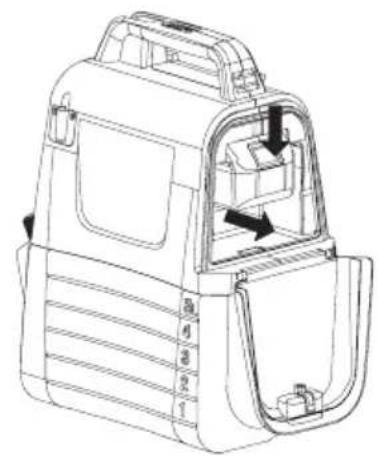
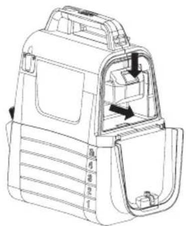
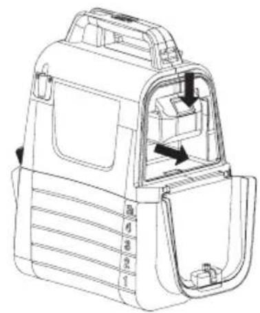
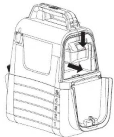
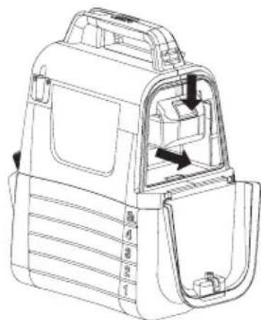
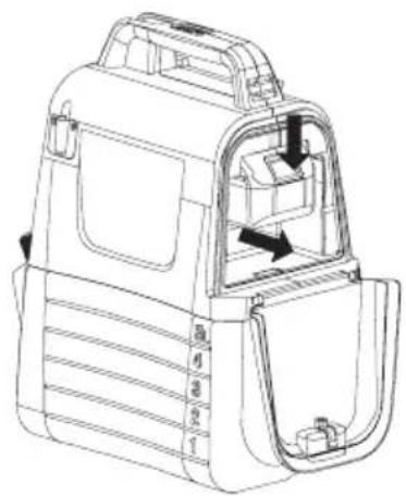
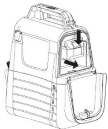
To install the battery cartridge, pull down the locking lever, and then open the battery cover. Align the tongue on the battery cartridge with the groove in the housing and slip it into place. Always insert it all the way until it locks in place with a little click. Refer to Figure 3.
To remove the battery cartridge, slide it from the machine while pressing the button. Refer to Figure 4.
natural_image
Technical line drawing of a mechanical device with internal components and mounting bracket (no text or symbols)
natural_image
Technical line drawing of a vehicle rear compartment showing internal compartments and structural details (no text or symbols)Figure 3 Figure 4
Indicating the residual battery capacity
Press the check button on the machine to indicate residual battery capacity. The indicator lamps light up for few seconds. Refer to Figure 5.
| Indicator lamps | Residual battery capacity | |
 | [02DW] | |
 | 50 % to 100 % | |
 | 30 % to 50 % | |
 | 0 % to 30 % | |
NOTE:
- Depending on the conditions of use and the ambient temperature, the indication may differ slightly from the actual capacity.
Figure 5
Machine / battery protection system
The machine is equipped with the protection system. This system automatically cuts off power to the motor to extend machine and battery life. The machine will automatically stop during operation if the machine or battery is placed under one of the following conditions.
- Overload protection: When the machine is operated in a manner that causes it to draw an abnormally high current, the machine automatically stops without any indication. In this situation, turn the machine off and stop the application that caused the machine to become overloaded. Then turn the machine on to restart.
- Overdischarge protection : When the battery capacity becomes low, the machine stops automatically. If the machine does not operate even when the switches are operated, remove the battery cartridge from the machine and charge it.
Indicating the remaining battery capacity
Only for battery cartridges with the indicator
| 1 | Indicator lamps | 2 | Check button |
Figure 6
Press the check button on the battery cartridge to indicate the remaining battery capacity. The indicator lamps light up for a few seconds.
| Indicator lamps | Remaining capacity | |
| Lighted Off | ||
| 75 % to 100 % | ||
| 50 % to 75 % | ||
| 25 % to 50 % | ||
| 0 % to 25 % | ||
NOTE: Depending on the conditions of use and the ambient temperature, the indication may differ slightly from the actual capacity.
Mixture

WARNING! Always follow the chemical manufacturer's instructions printed on their product labeling for use, cleaning, and storage. Clean thoroughly after each use, following the instructions in the Maintenance and cleaning section of this manual. Chemicals should be stored out of the reach of children. Failure to do so may result in serious personal injury.

WARNING! THE PRODUCT IS DESIGNED FOR SPRAYING CONSUMER-GRADE HOME AND GARDEN CHEMICALS SUCH AS WEED KILLERS, FUNGICIDES, INSECTICIDES, AND FERTILIZERS.

CAUTION: Be sure that no previously used chemical has been left in tank. If so, chemical reaction may occur generating harmful gas.

NOTICE: Do not over fill the tank. Doing so may damage the machine.

NOTICE: Liquids to be sprayed must be as thin as water. Thicker liquids will not spray properly.
- Remove the battery prior to adding chemical liquid to the tank.
- Hold the tank firmly and rotate it anti-clockwise so as to separate the motor housing from the tank. Refer to Figure 7.
- Unscrew and remove the measuring cup.
- Measure the recommended liquid. The cup can be used to measure up to 50 ml (2 oz) of liquid. Refer to Figure 8.
- Carefully pour the liquid into the tank with measuring cup through the filling opening of the tank. You can also dissolve chemical liquid in water completely in a separate container and then pour it into the tank. Make sure you always pour chemical liquid into the tank through the filling opening of the tank rather than small opening which is for measuring cup storage. Make sure that the tank filling strainer is in place. Refer to Figure 9.
- Rinse the measuring cup with clean water.
- Refit the cup, making sure it is tightened securely.
- Insert the hose into the depressed part of the tank filling strainer. Refer to Figure 10.
- Reattach the motor housing to the tank and rotate it clockwise to "Click". Refer to Figure 11.
*Container is not included.
OPERATION

WARNING! Risk of fire or explosion. Spray area must be well-ventilated and away from sparks or flames.

CAUTION:
When operating the machine, be sure to put the shoulder belt on your shoulder firmly.
Turning the machine on/off
- Before operating the machine, put on safety goggles and other safety gear.
- Press the On/off switch to start the machine.
- Press and hold the lever down to start spraying. Refer to Figure 12.
- Release the lever to stop spraying.
Lock-on
The lock-on feature is convenient for continuous spray or when covering a large area.
- To lock-on, press the lever down and pull the lock button backwards, then release the lever. Refer to Figure 13.
- To release the lock-on, press the lever and push the lock button forward.
Note: Make sure the lever is not in locked position before inserting the battery pack into the machine.
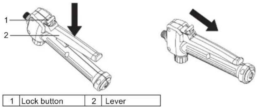
Figure 12 Figure 13
Adjustment to one-head type
- Turn the cock to the "lock" side to use the machine as one head type. Refer to Figure 14.
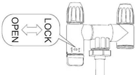
Figure 14
Adjusting spray
You can mist or jet the liquid using the adjustable spray head.
- Remove the battery pack from the machine.
- To mist the liquid, tighten the adjustable spray head.
- To jet the liquid, loosen the adjustable spray head.


Caution
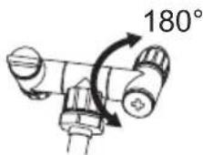
- Do not overturn cock exceeding 180^ . Disperse orifice may break.
- Do not touch nozzle lever by mistake when resting nozzle on nozzle stand to avoid erroneous spraying.
- Do not leave leftover chemical inside tank for a long period of time.
This would damage parts and shorten life of product.
Spraying

WARNING! Never set the unit on the ground during use. Avoid the machine and battery from getting wet at all times. Do not spray near or directly at the unit.
- Aim the sprayer nozzle directly at the plants or objects you wish to spray.
- Never point the spray end of the wand at yourself or others.
- Be aware of splash back, stand far enough from the object being sprayed to prevent the spray splashing back onto you.
- Never spray in the direction of people or animals; always spray downwind.
- Avoid spraying on windy days. Spray can be accidentally blown onto plants or objects that should not be sprayed.
MAINTENANCE AND CLEANING

CAUTION:
Always be sure that the machine is switched off and the battery cartridge is removed before attempting to perform inspection or maintenance.
To maintain product SAFETY and RELIABILITY, repairs, any other maintenance or adjustment should be performed by Makita Authorized or Factory Service Centers, always using Makita replacement parts.
MAINTENANCE

WARNING! To avoid serious personal injury, always remove the battery pack from the machine when cleaning or performing any maintenance.

WARNING! Always wear eye protection with side shields or goggles marked to comply with ANSI Z87.1. Failure to do so could result in fluids entering your eyes resulting in possible serious injury.

WARNING! When servicing, use only identical replacement parts. Use of any other parts may create a hazard or cause product damage.

WARNING! Do not at any time let brake fluids, gasoline, penetrating oils, etc., come in contact with plastic parts. Chemicals can damage, weaken, or destroy plastic which may result in serious personal injury.

NOTICE: Periodically inspect the entire product for damaged, missing, or loose parts such as screws, nuts, bolts, caps, etc. Tighten securely all fasteners and caps and do not operate this product until all missing or damaged parts are replaced. Please contact customer service or a qualified service center for assistance.

NOTICE:
Never use gasoline, benzine, thinner, alcohol or the like. Discoloration, deformation or cracks may result.
GENERAL MAINTENANCE: Avoid using solvents when cleaning plastic parts. Most plastics are susceptible to damage from various types of commercial solvents and may be damaged by their use. Use clean clothes to remove dirt, dust, oil, grease, etc.
CLEANING THE UNIT

WARNING! Always store and dispose of chemicals properly. Disposal of contaminated rinse water should be performed according to local ordinances and by laws.
DRAINING THE TANK
If there is any liquid left in the tank after spraying, the tank should be drained before cleaning.
- Remove the battery pack.
- Remove the motor housing from the tank.
- Drain the contents through the fill area.
NOTE: Drain the liquid back into the original container. Do not store chemical liquid in the tank.
CLEANING THE TANK
- Fill the tank about one-third full with clean water. A small amount of mild household detergent may be added.
NOTE: Never use flammable chemicals or abrasive cleaning agents to clean the tank.
- Wipe the outside of the tank with a clean, dry cloth.
• Reattach the motor housing to the tank.
- Reinstall the battery pack. Spray until the tank has been emptied. Make sure to direct the spray toward an area that will not be damaged by the spray solution.
- Refill and repeat the procedure with clean water. It may be necessary to rinse the tank more than once, then drain again as instructed above.
- Allow all parts to completely dry before reinstalling parts and storing the unit.
CLEANING THE NOZZLE
If the nozzle becomes plugged, use the steps below to clear.
- Remove the battery pack.
- Unscrew and remove the nozzle cap form adjustable spray head of the spray wand.
- Push a small wire through the exposed holes to clear any debris. Then flush with clean water. Refer to Figure 15
- Wipe the adjustable spray head with a clean dry cloth, and reattach the nozzle cap to the adjustable spray head.
natural_image
Technical line drawing of a mechanical device with a cylindrical component and a separate knob (no text or symbols)Figure 15
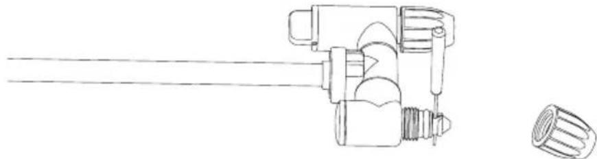
CLEANING THE PUMP
If the sprayer cannot draw the fluid from tank or it cannot spray out liquid at the first use or after long-term storage. Follow the procedures below to clean the pump:
- Switch off the machine and remove the battery.
- Remove the spray wand from handle.
- Drain any remaining liquid or store leftover liquid to another container to make sure the tank is empty.
- Separate the motor housing from the tank and turn it upside down. Refer to Figure 16.
- Unscrew the red cap to open water inlet hole, and then connect the hole to the water tap. Make sure the O-ring is placed inside the red cap.
- Open the water tap slowly and press down the lever at the same time to allow water flush away any debris adhered to the pump. Refer to Figure 17.
- Disconnect the water tap and re-tighten the red cap. Make sure that the O-ring inside the cap is in place.
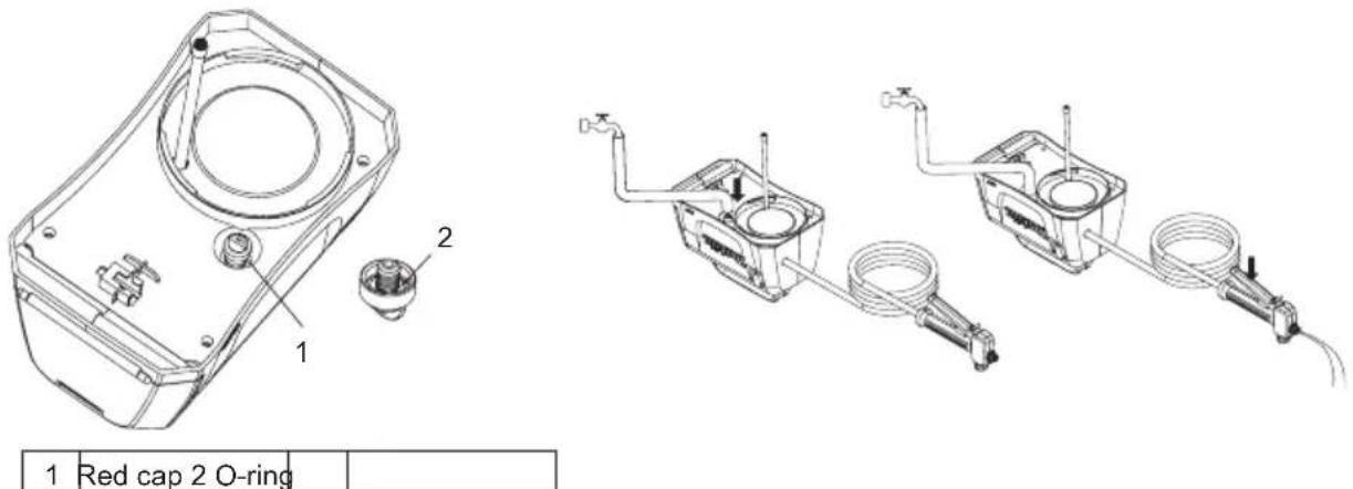
Figure 16 Figure 17
OPTIONAL ACCESSORIES

CAUTION:
These accessories or attachments are recommended for use with your Makita product specified in this manual. The use of any other accessories or attachments might present a risk of injury to persons. Only use accessory or attachment for its stated purpose.
If you need any assistance for more details regarding these accessories, ask your local Makita Service Center.
- Makita genuine battery and charger.
NOTE:
- Some items in the list may be included in the product package as standard accessories. They may differ from country to country.
natural_image
Line drawing of a person wearing a helmet and safety goggles (no text or symbols)natural_image
Technical line drawing of a mechanical device with internal compartments and housing (no text or symbols)Figura 3 Figura 4
natural_image
Technical line drawing of a vehicle rear compartment showing internal compartments and structural details (no text or symbols)Figura 14
Ajustando o pulverizador
natural_image
Technical line drawing of a mechanical assembly with no visible text or symbolsFigura 15
LIMPANDO A BOMBA
natural_image
Technical line drawings of two electrical heating devices with labeled components (no text or symbols present)natural_image
Line drawing of a person wearing a helmet and safety goggles (no text or symbols)natural_image
Technical line drawing of a mechanical device with no visible text or symbols
natural_image
Technical line drawing of a vehicle rear compartment showing internal compartments and structural details (no text or symbols)Figure 3 Figure 4
Figure 14
natural_image
Technical line drawing of a mechanical device with a cylindrical component and a separate knob (no text or symbols)Figure 15
NETTOYAGE DE LA POMPE
natural_image
Line drawing of a person wearing a helmet and safety goggles (no text or symbols)natural_image
Technical line drawing of a mechanical device casing with internal compartments and mounting brackets (no text or symbols)natural_image
Technical line drawing of a vehicle rear compartment showing internal compartments and structural details (no text or symbols)Abbildung 14
Spray einstellen
natural_image
Technical line drawing of a mechanical device with a shaft and knob (no text or symbols)Abbildung 15
PUMPE REINIGEN
natural_image
Technical line drawings of two electrical heating devices with labeled components (no text or symbols present)1 Rote Kappe 2 O-Ring
natural_image
Line drawing of a person wearing a helmet and safety goggles (no text or symbols)natural_image
Line drawing of a mechanical device with internal components and no visible text or symbolsFigura 3 Figura 4
natural_image
Technical line drawing of a vehicle rear compartment showing internal compartments and structural details (no text or symbols)
Figura 6
Figura 14
Spray regolante
natural_image
Technical line drawing of a mechanical assembly with no visible text or symbolsFigura 15
PULIZIA DELLA POMPA
natural_image
Line drawing of a person wearing a helmet and safety goggles (no text or symbols)FUNCTIONELE BESCHRIJVING

LET OP:
natural_image
Technical line drawing of a mechanical device casing with internal compartments and mounting bracket (no text or symbols)Figuur 3 Figuur 4
natural_image
Technical line drawing of a vehicle rear compartment showing internal compartments and doorways (no text or symbols)Figuur 14
natural_image
Technical line drawing of a mechanical device with a cylindrical component and a separate flanged part (no text or symbols)Figuur 15
SCHOONMAKEN VAN DE POMP
OPTIONELE ACCESSOIRES

LET OP:
natural_image
Line drawing of a person wearing a hard hat and safety goggles (no text or symbols)natural_image
Technical line drawing of a mechanical device with internal components and mounting bracket (no text or symbols)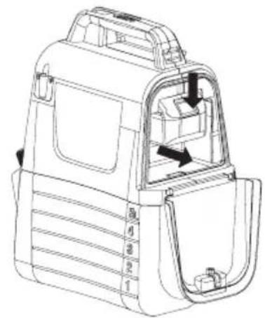
natural_image
Technical line drawing of a vehicle rear compartment showing internal compartments and structural details (no text or symbols)Figura 3 Figura 4
Figura 14
Ajustando el rocío
natural_image
Technical line drawing of a mechanical assembly with a shaft and flange (no text or symbols)Figura 15
natural_image
Technical line drawing of two mechanical components with hoses and valves, no text or symbols presentnatural_image
Line drawing of a person wearing a helmet and safety goggles (no text or symbols)natural_image
Technical line drawing of a mechanical device with internal components and mounting bracket (no text or symbols)
natural_image
Technical line drawing of a vehicle door frame with internal compartments and a directional arrow (no text or symbols)Figura 3 Figura 4
Figura 14
natural_image
Technical line drawing of a mechanical device with a shaft and knob (no text or symbols)Figura 15
LIMPAR A BOMBA
natural_image
Line drawing of a person wearing a helmet and safety goggles (no text or symbols)natural_image
Technical line drawing of a mechanical device with internal components and mounting bracket (no text or symbols)Figur 3 Figur 4
natural_image
Technical line drawing of a vehicle rear compartment showing internal compartments and doorways (no text or symbols)Indikerer batteriets kapacitet resterende

Figur 6
Figur 14
Juster sprayen
natural_image
Technical line drawing of a mechanical device with a cylindrical component and a separate knob (no text or symbols)Figur 15
Rengør pumpen
natural_image
Line drawing of a person wearing a hard hat and safety goggles (no text or symbols)natural_image
Technical line drawing of a mechanical device with numbered components (no text or symbols)Εικόνα 3 Εικόνα 4
natural_image
Technical line drawing of a vehicle rear compartment showing internal compartments and structural features (no text or symbols)Εικόνα 14
Προσαρμογή ψεκασμού
natural_image
Technical line drawing of a mechanical device with no visible text or symbolsΕικόνα 15
natural_image
Line drawing of a person wearing a helmet and safety goggles (no text or symbols)natural_image
Technical line drawing of a mechanical device casing with internal components (no text or symbols)Şekil 3 Şekil 4

natural_image
Technical line drawing of a vehicle rear compartment showing internal compartments and structural details (no text or symbols)Şekil 14
Ayarlama sprey
natural_image
Technical line drawing of a mechanical device with a cylindrical component and a separate knob (no text or symbols)Şekil 15
POMPANIN TEMİZLENMESİ
natural_image
Line drawing of a person wearing a helmet and safety goggles (no text or symbols)natural_image
Technical line drawing of a mechanical device with no visible text or symbolsFigur 3 Figur 4
natural_image
Technical line drawing of a car interior frame with no visible text or symbols| 1 | Indikatorlampor | 2 | Kontrollknapp |
Figur 6
Figur 14
natural_image
Technical line drawing of a mechanical device with a cylindrical component and a separate knob (no text or symbols)Figur 15
RENGÖRING AV PUMPEN
Figur 16 Figur 17
VALFRIA TILLBEHÖR
WARNING:
| 1 | Hodebryter cyster 2 Lengde | opp | mutteren 3 Håndtere. 4 Måle kopp | ||||
| 5 | Holder for sprøytestangen | 6 | kulderremmer 7 Batterideksel 8 | Justerbar dyse | |||
| 9 | pray pinne 10 Spaken. 11 | Slangen. 12 5L tank | |||||
| 13 | ndikatorlamper 14 Slå på | av 15 | Holder for sprøytestangen | 16 | Lås spaken | ||
| 17 | Krok (for tilkobling av spraystenger) - - - | ||||||
SPESIFIKASJONER
natural_image
Line drawing of a person wearing a helmet and safety goggles (no text or symbols)BRUK OG VEDLIKEHOLD AV TRÅDL∅SE HAGESPR∅YTERE
natural_image
Technical line drawing of a mechanical device casing with internal compartments and mounting bracket (no text or symbols)Figur 3 Figur 4

natural_image
Technical line drawing of a vehicle rear compartment showing internal compartments and structural details (no text or symbols)1 Indikatorlamper 2 Kontrollknapp
Figur 6
Figur 14
Juster sprayen
natural_image
Technical line drawing of a mechanical device with a cylindrical component and a separate knob (no text or symbols)Figur 15
RENGJ∅R PUMPEN
natural_image
Line drawing of a person wearing a hard hat and safety goggles (no text or symbols)natural_image
Technical line drawing of a mechanical device casing with numbered components (no text or symbols)Kuva 3 Kuva 4

natural_image
Technical line drawing of a car interior frame with numbered compartments and directional arrows indicating movement (no text or symbols)Kuva 14
Suihkun säätäminen
natural_image
Technical line drawing of a mechanical device with a cylindrical component and a separate knob (no text or symbols)Kuva 15
PUMPUN PUHDISTUS
natural_image
Line drawing of a person wearing a helmet and safety goggles (no text or symbols)natural_image
Technical line drawing of a mechanical device casing with internal components (no text or symbols)natural_image
Technical line drawing of a vehicle door frame with internal compartments and directional arrows indicating movement (no text or symbols)| 1 | Indikatorlampiñas | 2 | Pārbaudes poga |
Attēls nr.5
Attēls nr.14
natural_image
Technical line drawing of a mechanical device with a cylindrical component and a separate knob (no text or symbols)Attēls nr.15
SÜKNA TİRİŞANA
natural_image
Technical line drawings of a device with labeled components (no text or symbols present)natural_image
Line drawing of a person wearing a helmet and safety goggles (no text or symbols)
Pav. 2
FUNKCINIS APRAŠYMAS
DÉMESIO
natural_image
Technical line drawing of a mechanical device with internal components and mounting bracket (no text or symbols)Pav. 3 Pav. 4

natural_image
Technical line drawing of a vehicle rear compartment showing internal compartments and structural details (no text or symbols)Pav. 14
natural_image
Technical line drawing of a mechanical device with a cylindrical component and a separate knob (no text or symbols)Pav. 15
SIURBLIO VALYMAS
natural_image
Technical line drawings of a device with labeled components (no text or symbols present)
Pav. 16 Pav. 17
PASIRENKAMI PRIEDAI
DÈMESIO:
natural_image
Line drawing of a person wearing a helmet and safety goggles (no text or symbols)1 Riidepuu
Joonis 2
FUNKTSIONAALNE KIRJELDUS

ETTEVAATUST!
natural_image
Technical line drawing of a mechanical device with internal components (no text or symbols)Joonis 3 Joonis 4
natural_image
Technical line drawing of a car interior frame with internal compartments and directional arrows (no text or symbols)Joonis 14
natural_image
Technical line drawing of a mechanical device with a cylindrical component and a separate knob (no text or symbols)Joonis 15
PUMBA PUHASTAMINE
natural_image
Technical line drawings of a device with labeled components (no text or symbols present)1 Punane kork 2 O-helisema
Joonis 16 Joonis 17
VALIKULISED TARVIKUD

ETTEVAATUST!
natural_image
Line drawing of a person wearing a helmet and safety goggles (no text or symbols)natural_image
Technical line drawing of a mechanical device with internal components (no text or symbols)Rysunek 3 Rysunek 4
natural_image
Technical line drawing of a vehicle rear compartment showing internal compartments and structural details (no text or symbols)natural_image
Technical line drawing of a mechanical device with a cylindrical component and a separate flanged part (no text or symbols)Rysunek 15
CZYSZCZENIE POMPY
natural_image
Technical line drawings of a device with labeled components, including a housing and two temperature sensors (no text or symbols present)natural_image
Line drawing of a person wearing a helmet and safety goggles (no text or symbols)1 Akasztó
- Ábra
A KÉSZÜLÉK MÜKÖDÉSE ÉS FUNKCIÓI

VIGYÁZAT:
natural_image
Technical line drawing of a mechanical device casing with internal components (no text or symbols)
natural_image
Technical line drawing of a car interior compartment with no visible text or symbols- Ábra 4. Ábra
- Ábra
natural_image
Technical line drawing of a mechanical assembly with a shaft and flange (no text or symbols)- Ábra
natural_image
Technical line drawings of two electrical heating devices with labeled components (no text or symbols present)| 1 | Hlavný prepínací kohút | 2 | Predlžovacia matica | 3 | Rukovät' | 4 | Odmerka |
| 5 | podpora striekacej tyče | 6 | Ramienko | 7 | Kryt batérie | 8 | Nastavitel'ná striekacia hlava |
| 9 | Striekacia tyč | 10 | páčka | 11 | Hadica | 12 | Nádrž 5L |
| 13 | Svetlá indikátora | 14 | Vypínač | 15 | Držiak striekacej tyče | 16 | Uzamykacia páčka |
| 17 | Háčik (na pripevnenie striekacej tyče) | - | - | - | - | ||
TECHNICKÉ ÚDAJE
natural_image
Line drawing of a person wearing a helmet and safety goggles (no text or symbols)TIETO POKYNY USCHOVAJTE.
natural_image
Technical line drawing of a mechanical device casing with internal components and mounting bracket (no text or symbols)Obrázok 3 Obrázok 4

natural_image
Technical line drawing of a vehicle rear compartment showing internal compartments and structural details (no text or symbols)| 1 | Svetlá indikátora | 2 | Tlačidlo kontroly |
Obrázok 5
Systém ochrany zariadenia/batérie
| 1 | Svetlá indikátora | 2 | Tlačidlo kontroly |
Obrázok 6
Obrázok 14
Uprava spreja
natural_image
Technical line drawing of a mechanical device with a cylindrical component and a separate knob (no text or symbols)Obrázok 15
ČISTENIE ČERPADLA
natural_image
Technical line drawings of a mechanical device with labeled parts (1 and 2), showing internal components and wiring connections (no text or symbols present)natural_image
Line drawing of a person wearing a helmet and safety goggles (no text or symbols)
Obrázek 2
FUNKČNÍ POPIS

POZOR:
natural_image
Technical line drawing of a mechanical device casing with internal compartments and mounting bracket (no text or symbols)Obrázek 3 Obrázek 4
natural_image
Technical line drawing of a vehicle rear compartment showing internal compartments and doorways (no text or symbols)Obrázek 14
Nastavení postřiku
natural_image
Technical line drawing of a mechanical device with a cylindrical component and a separate knob (no text or symbols)Obrázek 15
ČIŠTĚNÍ ČERPADLA
natural_image
Technical line drawings of a device with labeled components (no text or symbols present)VOLITELNÉ PŘÍSLUŠENSTVÍ

POZOR:
natural_image
Line drawing of a person wearing a helmet and safety goggles (no text or symbols)1 Obešalnik
Slika 2
FUNKCIONALNI OPIS

POZOR:
natural_image
Technical line drawing of a mechanical device with internal components and mounting bracket (no text or symbols)Slika 3 Slika 4
natural_image
Technical line drawing of a vehicle door frame with internal compartments and directional arrows indicating movement (no text or symbols)Navedba preostale kapacitete baterije
| 1 | Kontrolne lučke | 2 | Gumb za preverjanje |
Slika 6
Pritisnite gumb za preverjanje na vložku za baterije, da preverite preostalo zmogljivost baterije. Lučke pokazatelja zasvetijo za nekaj sekund.
| Kontrolne lučke | Preostala zmogljivost | |
| Osvetljeno lzklopljeno | ||
| 75 % do 100 % | ||
| 50 % do 75 % | ||
| 25 % do 50 % | ||
| 0 % do 25 % | ||
Slika 14
Nastavitev curka
natural_image
Technical line drawing of a mechanical device with a cylindrical component and a separate knob (no text or symbols)Slika 15
ČIŠČENJE ČRPALKE
natural_image
Line drawing of a person wearing a helmet and safety goggles (no text or symbols)natural_image
Technical line drawing of a mechanical device casing with internal components (no text or symbols)
natural_image
Technical line drawing of a car interior compartment with labeled parts (no text or symbols)Figura 3 Figura 4
| 1 | Drita e treguesit | 2 | Butoni i kontrollit |
Figura 6
Figura 14
Llak rregullues
natural_image
Technical line drawing of a mechanical device with a shaft and knob (no text or symbols)Figura 15
PASTRIMI I POMPES
Figura 16 Figura 17
AKSESORË OPSIONALË

KUJDES:
natural_image
Line drawing of a person wearing a helmet and safety goggles (no text or symbols)natural_image
Technical line drawing of a mechanical device with internal components and mounting bracket (no text or symbols)Фигура 3 Фигура 4
natural_image
Technical line drawing of a vehicle rear compartment showing internal compartments and doorways (no text or symbols)Фигура 14
Регулиращо пръскане
natural_image
Technical line drawing of a mechanical device with a cylindrical component and a separate knob (no text or symbols)Фигура 15
| 1 | Prekidač za prebacivanje mlaznice prskalice | 2P | produžna matica 3Drška4Mjerna | čaša | ||
| 5 | Podupirač za štapić za prskanje | 6N | aramenica 7Poklopac za bateriju | 8 | Podesiva mlaznica za prskanje | |
| 9 | Štapić za prskanje | 10 | Poluga | 11 | Crijevo | 12 5L spremnik |
| 13L | ampice indikatora 14Sklopka | On/off 15 | Držač za štapić za prskanje | 16Poluga za zaključavanje | ||
| 17 | Kuka(za pričvršćivanje štapić za prskanje) | - | - | - | ||
SPECIFIKACIJE
| Model US053D | ||
| Nazivni napon D.C. 10,8 V - 12 V maks. | ||
| Kapacitet spremnika 5 L | ||
| Duljina crijeva 1,7 m | ||
| Ukupna proširena duljina 50 - 70 cm | ||
| Vrsta mlaznice 2-mlaznice (može se promijeniti u 1 mlaznicu) | ||
| Maksimalni radni tlak 0,3 MPa | ||
| Radni tlak sa standardnom mlaznicom | Maks. Oko 0,26 Mpa | |
| Min.Oko 0,13 Mpa | ||
| Protok standardne mlaznice | Maks. Oko 0,91 L/min | |
| Min.Oko 0,47 L/min | ||
| Vijak mlaznice G 1/4" | ||
| Veličina (D × Š × V) 343 × 182 × 343 mm | ||
| Neto težina 2,9 - 3,0 kg | ||
- Zbog našeg kontinuiranog programa istraživanja i razvoja navedene se specifikacije mogu promijeniti bez obavijesti.
- Specifikacije se mogu razlikovati od zemlje do zemlje.
Težina se može razlikovati ovisno o dodacima, uključujući uložak baterije. Najlakša i najteža kombinacija prema EPTA postupku 01/2014 prikazane su u tablici.
natural_image
Line drawing of a person wearing a helmet and safety goggles (no text or symbols)Slika 2.
FUNKCIONALNI OPIS

OPREZ:
natural_image
Technical line drawing of a mechanical device casing with numbered parts (1-9), no text or symbols present.
natural_image
Technical line drawing of a car interior frame with numbered compartments and directional arrows indicating movement (no text or symbols)Slika 3. Slika 4.
Pokazivanje ostatka kapaciteta baterije.
Pritisnite gumb na stroju kako biste pokazali ostatak kapaciteta baterije. Lampica indikatora se uključuje na nekoliko sekundi. Pogledajte Sliku 5.
| Lampice indikatora | Ostatak kapaciteta baterije | |
| Osvijetljeno | Isključeno | |
| 50 % do 100 % | ||
| 30 % do 50 % | ||
| 0 % do 30 % | ||
NAPOMENA:
Slika 14.
Prilagodljiva mlaznica
natural_image
Technical line drawing of a mechanical assembly with no visible text or symbolsSlika 15.
Čišćenje pumpe
natural_image
Line drawing of a person wearing a hard hat and safety goggles (no text or symbols)1 Закачалка
Слика 2
ОПИС НА ФУНКЦИЈАТА

ВНИМАНИЕ:
natural_image
Technical line drawing of a mechanical device casing with internal compartments and mounting bracket (no text or symbols)Слика 3 Слика 4
natural_image
Technical line drawing of a car interior frame with no visible text or symbolsСлика 14
Прилагодлив спреј
natural_image
Technical line drawing of a mechanical device with a cylindrical component and a separate cylindrical part (no text or symbols)Слика 15
ЧИСТЕЊЕ НА ПУМПАТА
natural_image
Technical line drawings of a device with labeled components (no text or symbols present)natural_image
Line drawing of a person wearing a helmet and safety goggles (no text or symbols)natural_image
Technical line drawing of a mechanical device with internal components and mounting bracket (no text or symbols)Слика 3 Слика 4
natural_image
Technical line drawing of a car interior panel with no visible text or symbolsСлика 14
Подесива млазница
natural_image
Technical line drawing of a mechanical device with a cylindrical component and a separate knob (no text or symbols)Слика 15
Чишћење пумпе
natural_image
Technical line drawings of a mechanical device with labeled parts (1, 2), showing internal components and wiring connections (no text or symbols present)| 1 | Cap robinet 2 Piulita de extensie 3 Maner 4 Cana de masurare | |||||
| 5 | Suport lance de pulverizare | 6 | Curea de umar 7 Capacul acumulatorului 8 | Cap de pulverizare reglabil | ||
| 9 | Lance de pulverizare reglabila | 10 | Parghie 11 Furtun 12 Rezervor de 5L | |||
| 13 | Lămpi indicatoare 14 Intrerupator pornire/oprire 15 | Suport lance de pulverizare | 16 | Maneta de blocare | ||
| 17 | Carlig (pentru fixarea lancei de pulverizare) - - - - | |||||
Date tehnice
natural_image
Line drawing of a person wearing a helmet and safety goggles (no text or symbols)natural_image
Technical line drawing of a mechanical device casing with internal components (no text or symbols)
natural_image
Technical line drawing of a vehicle rear compartment showing internal compartments and structural details (no text or symbols)Figura 3 Figura 4
| 1 | Lămpi indicatoare | 2 | Buton de verificare |
Figura 6
Figura 14
Reglarea spray-ului
natural_image
Technical line drawing of a mechanical device with a cylindrical component and a separate knob (no text or symbols)Figura 15
CURATAREA POMPEI
natural_image
Technical line drawing of a mechanical housing with labeled components (no text or symbols present)1 Capacul rosu 2 |helul- O
natural_image
Technical line drawing of two mechanical components with hoses and valves, no text or symbols presentFigura 16 Figura 17
ACCESORII OPTIONALE
ATENTIE:
natural_image
Line drawing of a person wearing a helmet and safety goggles (no text or symbols)natural_image
Technical line drawing of a mechanical device casing with internal components (no text or symbols)
natural_image
Technical line drawing of a vehicle rear compartment with internal compartments and directional arrows (no text or symbols)Мал. 3. Мал. 4.
Мал. 14.
natural_image
Technical line drawing of a mechanical device with a cylindrical component and a separate knob (no text or symbols)Мал. 15.
ОЧИЩЕННЯ НАСОСА
natural_image
Technical line drawings of two electrical heating devices with labeled components (no text or symbols present)natural_image
Line drawing of a person wearing a helmet and safety goggles (no text or symbols)natural_image
Line drawing of a mechanical device with internal components and no visible text or symbolsРис. 3 Рис. 4

natural_image
Technical line drawing of a vehicle rear compartment showing internal compartments and structural details (no text or symbols)Рис. 14
natural_image
Technical line drawing of a mechanical device with a cylindrical component and a flanged part (no text or symbols)Рис. 15
ЧИСТКА НАСОСА
natural_image
Technical line drawings of a device with labeled components (no text or symbols present)natural_image
Line drawing of a person wearing a hard hat and safety goggles (no text or symbols)natural_image
Technical line drawing of a mechanical device with no visible text or symbols3-Cypet 4-Cypet
natural_image
Technical line drawing of a vehicle rear compartment showing internal compartments and doorways (no text or symbols)
5-Cypet

6-Cypet
ПАЙДАЛАНУ

14-Cypet
Шашыраткышты теңшеу
natural_image
Technical line drawing of a mechanical device with no visible text or symbols15-Cypet
ТАЗАРТКЫШ НАСОС
natural_image
Technical line drawings of a device with labeled components (no text or symbols present)natural_image
Line drawing of a person wearing a helmet and safety goggles (no text or symbols)natural_image
Technical line drawing of a vehicle chassis with numbered compartments (no text or symbols)圖3圖4

natural_image
Technical line drawing of a vehicle rear compartment showing internal compartments and structural details (no text or symbols)電池剩餘容量指示
1 指示燈 2 檢查按鈕
圖6
圖 14
調節噴灑
可使用可調節噴頭霧化或液體。
natural_image
Technical line drawing of a mechanical assembly (no text or symbols)15 شكل
تميزکاری یمپ
natural_image
Technical line drawing of a mechanical device with labeled components (no text or symbols present)1 2 کلاهک قرمز ۱
17 شکل 16 شکل
13 شکل 12
تعويض به نوع یک سره
1 2 3 4 5 6 7 8 9 10 11 12 13 14 15 16 17 18 19 20 21 22 23 24 25 26 27 28 29 30
5 شكل
natural_image
Technical line drawing of a car interior compartment with numbered compartments and directional arrows indicating movement (no text or symbols)
natural_image
Technical line drawing of a mechanical device casing with internal components and mounting bracket (no text or symbols)شکل 4 شکل 3
مونتاز
احتياط:

2 شكل
The image contains no text. The horizontal lines are stylistic or background elements and must be ignored according to the rules.
Makita
Makita
The image contains no legible text or symbols. The OCR result "0" is a hallucination and does not correspond to any content in the source image. Therefore, the correct OCR output must reflect the absence of any visible characters.
(no text)
□□□□□□□□□□□□□□□□□□□□□□□□□□□□□□□□□□□□□□□□□□□□□□□□
□□□□□□□□□□□□□□□□□□□□□□□□□□□□□□□□□□□□□□□□□□□□□□□□□□□□□□□□□□□□□□□□□□□□□□□□□□□□□□□□□□□□□□□□□□□□□□□□□
□□□□□□□□□□□□□□□□□□□□□□□□□□□□□□□□□□□□□□□□□□□□□□□□□□□□□□□□□□□□□□□□□□□□□□□□□□□□□□□□□□□□□
□□□□□□□□□□□□
□□□□□□□□□□□□□□□□□□□□□□□□□□□□□□□□□□□□□□□□□□□□□□□□□□□□□□□□□□□□□□□□□□□□□□□□□
□□□□□□□□□□□□□□□□□□□□□□□□□□□□□□□□□□□
natural_image
Line drawing of a person wearing a helmet and safety goggles (no text or symbols)natural_image
Technical line drawing of a mechanical assembly with no visible text or symbols15 alشكل

تنظيف المضخة
natural_image
Technical line drawing of a mechanical device housing with labeled parts (no text or symbols present)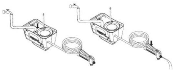
natural_image
Technical line drawing of two mechanical components with hoses and valves, no text or symbols present
16 الشكل 17 الشكل

5 الشكل

natural_image
Technical line drawing of a car interior frame with numbered compartments and directional arrows indicating movement (no text or symbols)الشكل 3 الشكل 4
natural_image
Technical line drawing of a mechanical device casing with internal components and mounting bracket (no text or symbols)
2 الشكل