EURO 8/24 - Compressor EINHELL - Free user manual and instructions
Find the device manual for free EURO 8/24 EINHELL in PDF.

User questions about EURO 8/24 EINHELL
0 question about this device. Answer the ones you know or ask your own.
Ask a new question about this device
Download the instructions for your Compressor in PDF format for free! Find your manual EURO 8/24 - EINHELL and take your electronic device back in hand. On this page are published all the documents necessary for the use of your device. EURO 8/24 by EINHELL.
USER MANUAL EURO 8/24 EINHELL
© Please pull out page 2
© Desdobre as página 2
⑤ Fäll upp sidoma 2
Note the directions for use!
Beware of hot surfaces
natural_image
Simple line drawing of a container with a lid and a handle, no text or symbols presenttext_image
Diagram of an automotive engine compartment with numbered parts labeled ①, ②, and ③natural_image
Mechanical component diagram showing a spring and housing assembly (no text or symbols)D
General safety instructions
Important! The following basic safety precautions have to be taken when using this compressor in order to guard against the risk of electric shock, injury and fire. Read and note these instructions before you use the compressor.
- Keep your work area tidy
- There is a higher risk of accident in an untidy work area.
- Make allowance for
environmental conditions - Never leave the compressor in the rain. Never use the compressor in damp or wet conditions. Provide good lighting. Never use the compressor near combustible liquids or gases.
- Protect yourself from
electric shocks - Avoid physical contact with earthed parts, e.g. pipes, radiators, cookers, refrigerators.
- Keep children away!
- Do not allow other persons to touch the compressor or its cable. Keep them out of your work area.
- Keep your compressor in a safe place
- When the compressor is not being used it should be kept in a dry, locked room out of the reach of the children.
- Do not overload your compressor
- It is better and safer to work within the quoted power range.
- Wear suitable work clothes
-
Do not wear loose garments or jewellery. There is a risk of them catching on moving parts. Rubber gloves and non-slip shoes are recommended when working outdoors. Put on a hair net if you have long hair.
-
Wear goggles
- Wear a breathing mask when working in dusty conditions.
- Never use the cable for any purpose other than that intended
Never tow the compressor by its cable and never pull the power plug out of the socket by the cable. Protect the cable from heat, oil and sharp edges.
- Do not overreach
- Avoid abnormal postures. Stand squarely and keep your balance at all times.
- Look after your compressor - Keep your compressor clean so that it works well and reliably. Follow the
maintenance instructions. Check the power plug and cable regularly and have them replaced by a specialist if you discover any damage. Check any extension cables regularly and replace if damaged.
- Pull out the power plug
- Whenever the compressor is not being used and before carrying out any maintenance work.
- Do not leave any tools on
the compressor - Before you switch on the compressor, make sure that all wrenches and setting tools have been removed.
- Avoid accidental starts
-
Make sure that the switch is turned to OFF before you connect the compressor to the power supply.
-
Extension cables for outdoor use
- Use extension cables outdoors only if they are approved and marked accordingly.
- Concentrate at all times
-
Watch your work. Be sensible. Do not use the compressor if your mind is not on your work.
-
Examine your compressor for signs of damage Before you use the
Before you use the compressor again, carefully check its safety devices or any slightly damaged parts to make sure that they are
working properly and as intended. Check moving parts to make sure that they are in good working order and are not jammed or damaged. All parts have to be properly fitted in order to be sure of meeting all the machine's requirements.
Damaged safety devices and parts have to be repaired or replaced by a customer service workshop unless otherwise stated in this manual. Damaged switches have to be replaced by a customer service workshop. Do not use any tools with a switch that cannot be turned on and off.
- Important!
-
For your own safety, use only such accessories and auxiliary equipment as are listed in this manual or which are recommended and specified by the manufacturer. There is a high risk of suffering a serious accident if you use tools or accessories which are not listed in this manual or in the catalogue of recommended tools and accessories.
-
Have an electrician carry out repairs
- Repairs are to be carried out only by a qualified electrician. If not, the user may suffer serious accidents.
- Connect a dust extraction
system - If there are facilities for connecting a dust extraction system, check that the system is indeed connected and being used.
- Noise
- The compressor's noise is measured in accordance with IEC 59 CO 11, IEC 704, DIN 45635 Part 21, and NFS 31-031 (84/537/EEC). The machine noise may exceed 85 dB(A) at the workplace. In this case, noise protection measures need to be introduced for the user.
Keep these safety instructions in a safe place.
GB
GB
Read this manual carefully before putting the compressor into operation!
| Technical data EURO 2200-1 | |
| Power supply 230 V ~ 50 Hz | |
| Motor rating in kW/h.p. 1,5 / 2 | |
| Compressor speed in rpm 2850 | |
| Operating pressure in bar 8 | |
| Pressure vessel volume in litre 24 | |
| Theoretical intake rate in l/min. 210 | |
| Sound power level LWA in dB(A) 97 | |
| Sound pressure level LPA in dB(A) 87 | |
| Protection type IP 20 | |
| Machine weight in kg 31 | |
| Art.-Nr.: 40.072.50 | |
| I-Nr. 01043 |
The machine is radio-suppressed in accordance with EC Guidelines 82/499 EEC.
The unit is not intended for outdoor operation as per Article 3 of EC Directive 2000/14/EC.
Points to note when setting up the compressor
☐ Examine the machine for signs of transit damage. Report any damage immediately to the company which delivered the compressor.
Before you put the compressor into operation, check the oil level in the compressor pump.
II The compressor should be set up near the working consumer
☐ Avoid long air lines and long supply lines (extensions).
11 Make sure the intake air is dry and dust-free
☐ Do not set up the compressor in damn or wet rooms.
The compressor may only be used in suitable rooms (with good ventilation and an ambient temperature from +5°C to +40°C). There must be no dust, acids, vapors, explosive gases or inflammable gases in the room.
☐ The compressor is designed to be used in dry rooms. It is prohibited to use the compressor in areas where
work is conducted with sprayed water.
Safety instructions for working with compressed air and paint sprayers
Important! Note the pertinent accident prevent regulations in force in your area!
Compressors and lines reach high temperatures during operation. Avoid contact! Risk of burns!
Gases or vapours drawn in by the compressor have to be kept free of constituents that may cause fire or explosions inside the compressor.
When you disconnect the hose coupling, hold the coupling element in your hand to prevent injury from the whiplashing hose. Wear goggles when working with the blow-out gun. Injuries may easily result from foreign bodies and blasted parts.
Never point the blow-out gun at other persons and never use it to clean clothes that are still being worn.
Note the safety instructions for paint spraying!
Important! Note the pertinent accident prevent regulations in force in your area!
Never process paints or solvents with a flash point below 21°C.
Never heat paints or solvents.
It is imperative to use filtering equipment (face masks) when processing harmful liquids. Note also the information concerning safety precautions published by the manufacturers of these liquids.
☐ Smoking is prohibited during the spraying operation and in the work room. Paint vapours are highly flammable.
Make sure there are no open fires or open lights in the work room. Sparking machines are not to be used.
Do not keep or consume food and drink in the work room. Paint vapours are harmful.
The work room has to be bigger than 30 m ^2 and have sufficient ventilation for spraying and drying. Never spray into the wind.
It is always imperative to observe the regulations of your local police authorities when spraying combustible or hazardous substances.
Never process media such as white petroleum spirit, butyl alcohol and methylene chloride with the PVC pressure hose (reduced life span).
Operation of pressure vessels in accordance with the pertinent pressure vessel
regulations (e.g. Section 13 of the German Pressure Vessel Act)
- An operator of a pressure vessel is required to keep the pressure vessel in good working order, to operate it properly, to supervise its use, to carry out essential maintenance and repair work immediately, and to introduce essential safety measures according to requirements.
- The supervisory authorities may order essential safeguards from case to case.
- A pressure vessel may not be operated if it has any defects which constitute a danger to employees or third parties.
- If pressure vessels of groups III, IV, VI and VII suffer damage
to any pressure-bearing walls, resulting in them being taken out of operation in accordance with Section 13 Paragraph 3 of the German Pressure Vessel Act, the operator has to notify the supervisory authorities and discuss what action is to be taken.
Putting the compressor into operation
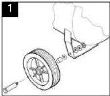
Assembling the wheels (1): Fit the wheels as shown in Figure 1.
text_image
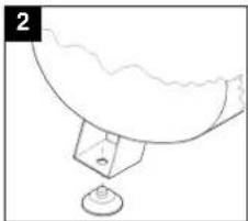
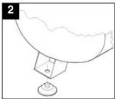
1Assembling the rubber buffer Fit the supplied rubber buffer to the support foot as shown in Figure 2.
natural_image
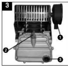
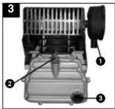
Simple line drawing of a bowl with a stand and a small container, no text or symbols presentReplacing the oil filter and installing the air filter (fig. 3) Use a screwdriver to remove the oil filler plug and insert the supplied stopper (2) in the opening.
Important! Check the oil level. Screw the air filter (1) into the hole in the side of the compressor pump.
GB
text_image
Labeled diagram of an electric motor showing three components: fan, battery, and motor.Connecting to the power supply:
The EURO 2200 compressor is equipped with a power cable and an earthing-pin plug for connection to any 230 V \~ 50 Hz earthing-contact socket outlet with a 16 A fuse. Long supply lines, extensions, cable reels and similar cause voltage dips and may prevent the motor from starting. Sluggishness makes starting difficult at low temperatures under freezing point (0°C).
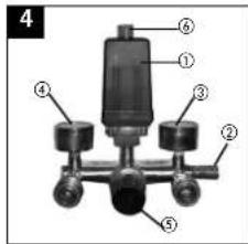
Explanation of the compressed air fittings
1 Pressure switch
2 Safety valve
3 Pressure gauge (to indicate the vessel pressure)
4 Pressure gauge (to indicate the set pressure)
5 Pressure reducing valve (pressure setting)
6 On/Off switch
text_image
4 ① ② ③ ④ ⑤11
GB
Maintenance and cleaning
Condensation water
Let out the condensation water daily by opening the drain valve (bottom of the pressure vessel).
|| Safety valve
The safety valve is set to the maximum pressure of the pressure vessel. It is prohibited to adjust the safety valve or to remove its lead seal.
Regular oil level checks
The level of oil has to be visible in the sight-glass between the red check-point mark and the upper edge of the sight-glass. Changing the oil:
Recommended grade SAE 15W/40 or equivalent.
The first oil change should be carried out after 100 operating hours. Thereafter you should drain the oil and replace it with new oil at intervals of 500 operating hours.
Changing the oil
Switch off the motor and pull the power plug out of the socket-outlet. After letting off any air pressure you can remove the oil drain plug from the compressor pump by unscrewing. To prevent the oil escaping out of control, hold a small piece of metal guttering underneath the drain plug to direct the oil into a container. If any oil still remains inside, till the compressor a little.
Take the old oil to an official old oil disposal station. When the old oil has run out, screw the oil drain plug/sight-glass back in place.
Use a screwdriver to remove the cap of the oil filler plug and fill in oil until the level of oil in the sight-glass reaches the red mark.
Then put the cap back on the oil filler plug.
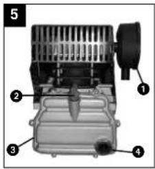
1 Filter
2 Oil filler plug
3 Oil drain plug
4 sight-glass
text_image
5 ① ② ③ ④□ Cleaning the intake filter
The intake filter prevents dust and dirt being drawn into the machine. This filter has to be cleaned at intervals of no longer than 300 operating hours. A clogged intake filter has a considerable negative effect on the compressor's power.
The filter can be removed as shown in Figure 4. Wash out the filter with petroleum ether and reinsert.
Caution! Wait until the compressor has cooled completely!
Risk of burns!
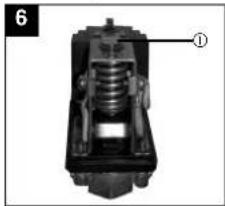
Setting the pressure switch
The pressure switch is set at the factory.
Switch-on pressure 5 bar Switch-off pressure 8 bar
To adjust the differential pressure, proceed as follows: Take the cover hood off the pressure
switch (unscrew the screw plug). Use an 8 mm socket wrench on screw 1 to adjust the differential pressure DP. Tum clockwise to increase the differential pressure and raise the switch-off pressure. Tum anticlockwise to decrease the differential pressure and lower the switch-off pressure.
natural_image
Mechanical component diagram showing a spring assembly with labeled part (1), no readable text or symbols present.Possible causes of machine failure
Overloading of the motor and hence triggering of the overload circuit-breaker may result from:
] An excessively high mains voltage
Excessively high ambient temperatures and an insufficient air supply
☐ Defective compressor valves or a leaking non-return valve
A low level of oil, sluggish connecting rod bearings
Leave a.c. motors enough time to cool off before switching on again. Avoid touching hot components and pipe lines.
Ordering replacement parts
Please quote the following data when ordering replacement parts:
] Type of machine
1 Article number of the machine
Identification number of the machine
Replacement part number of the part required
natural_image
Simple line drawing of a container with a handle and a small container, no text or symbols presenttext_image
Labeled diagram of an electric motor showing three components: fan, battery, and motor.natural_image
Mechanical component diagram showing internal spring assembly (no text or symbols)natural_image
Simple line drawing of a bowl with a small container and a stand, no text or symbols presentReplacing the oil filter and installing the air filter(3) Use a screwdriver to remove the oil filler plug and insert the supplied stopper (2) in the opening. Important! Check the oil level. Screw the air filter (1) into the hole in the side of the compressor pump.
text_image
Labeled diagram of a mechanical device with numbered components, likely an engine or motor assembly.natural_image
Mechanical component diagram showing a spring assembly with labeled part (1), no readable text or symbols present.NL
natural_image
Simple line drawing of a bowl with a stand and a small object, no text or symbols presenttext_image
Labeled diagram of a mechanical device with numbered componentsConexión eléctrica:
natural_image
Mechanical component diagram showing internal spring and housing (no text or symbols)text_image
1 12.0 40.0 40.0natural_image
Simple line drawing of a container with liquid and a stand, no text or symbols presenttext_image
Labeled diagram of a mechanical device with numbered componentsConexão eléctrica:
natural_image
Mechanical component diagram showing internal spring and housing (no text or symbols)P
natural_image
Simple line drawing of a bowl with a stand and a small object, no text or symbols presentnatural_image
Mechanical component diagram showing a piston-like structure with internal springs and housing (no text or symbols)Möjliga felorsaker
text_image
1 12-4 40-8-8Kumipuskurln asennus (2):
natural_image
Simple line drawing of a bowl with a stand and a small object, no text or symbols presenttext_image
Diagram of a vehicle engine compartment with numbered parts labeled 1, 2, and 3Sähköliitäntä:
Kompressori EURO 2200 on
natural_image
Simple line drawing of a bowl with a small container and a wavy top, no text or symbols presenttext_image
Labeled diagram of an electric motor showing three components: fan, battery, and motor.Elektrisk tilkobling:
Kompressoren EURO 2200 or utsyrft med en nettledning og et beskyttelsessøpsel. Denne kan settes i enhver beskyttet stikkontakt med 230 V \~ 50 Hz som er sikret med 16A. Lange tilslutningsledninger og forlengringer, kabeltromler osv. fører til trykkfäll og kan forhindre motorstarten. Ved lave temperaturer på under 0 °C kan det være vanskelig å starte motoren p.g.a. lungkjorthet.
natural_image
Mechanical component diagram showing internal spring assembly with labeled part (1), no readable text or symbols present.natural_image
Simple line drawing of a bowl with a small container and a base, no text or symbols presenttext_image
Labeled diagram of an electric motor showing three components: fan, battery, and motor.Ηλεκτρική σύνδεση:
natural_image
Simple line drawing of a bowl with a stand and a small container, no text or symbols presenttext_image
Labeled diagram of an industrial machine with numbered componentsnatural_image
Mechanical component diagram showing internal spring and housing (no text or symbols)53
I
natural_image
Simple line drawing of a bowl with a stand and a small object at the base (no text or symbols)text_image
Labeled diagram of an electric motor showing three components: fan, battery, and motor.El-tilslutning:
Indkoblingstryk 5 bar
Udkoblingstryk 8 bar
natural_image
Mechanical component diagram showing internal spring assembly (no text or symbols)Mulige fejlårsager
som kan føre til en overbelastning af motoren og dermed til, at overbelastningssikringen reagerer:
natural_image
Simple line drawing of a bowl with a stand and a small container, no text or symbols presenttext_image
Labeled diagram of an electric motor showing three components: fan, battery, and motor.natural_image
Simple line drawing of a bowl with a stand and a small container, no text or symbols presenttext_image
Labeled diagram of an electric motor showing three components: fan, battery, and motor.text_image
Labeled diagram of an industrial machine with numbered components for identificationtext_image
1 CNC 100mmMontaža gumijastega
blažilnika:
natural_image
Simple line drawing of a bowl with a stand and a small object, no text or symbols presenttext_image
Labeled diagram of an electric vehicle showing three components: fan, battery, and motor.Električni priklop:
natural_image
Mechanical component diagram showing a spring assembly with labeled part (1), no readable text or symbols present.text_image
1 L2.04 A2.05Montaža gumenog odbojnika:
Priloženi gumeni odbojnik se mora montirati na nožicu kao što je prikazano na crtežu 2.
natural_image
Simple line drawing of a bowl with a stand and a label '2' (no text or symbols on the diagram itself)text_image
Labeled diagram of an electric vehicle battery showing internal components and parts numbered 1, 2, and 3.natural_image
Mechanical component diagram showing internal spring assembly (no text or symbols)text_image
Exploded view diagram of a mechanical device with numbered parts for identification76
The guarantee period begins on the sales date and is valid for 2 years.
Responsibility is assumed for faulty construction or material or functional defects.
Any necessary replacement parts an necessary repair work are free of charge.
We do not assume responsibility for consequential damage.
Your customer service partner
F GARANTIE
yu MP Trading d.o.o.
Cika Ljubina 8/IV
YU 11000 Beograd
GR An. Mavrofidopoulos S.A.
Technical & Commercial company
12, Papastratou & Asklipiou Str.
GR 18545 Piräus
Tel 0210 4136155, Fax 0210 4137692
RUS Bermas
Altufyevskoye shosse. 2A
RUS 127372 Moscowi
Tel 095 3639580, Fax 095 3639581
EH 07/2003