
TVHS20040 - Security and Access Control System ABUS - Free user manual and instructions
Find the device manual for free TVHS20040 ABUS in PDF.
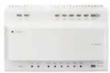
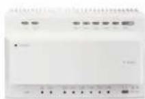
| Product type | Information module for MODUVIS video intercom system |
| Brand | ABUS |
| Model | TVHS20040 |
| Cabling technology | Compatible 2-wire and IP via system bus |
| Power supply | Via system bus (power supplied by distributor or PoE switch) |
| Power consumption | < 2 W (estimated) |
| Housing material | Weather-resistant plastic (recommended for outdoor use) |
| Protection rating | IP44 (estimated) |
| Operating temperature | -20 °C to +50 °C (estimated) |
| Dimensions (W x H x D) | Approximately 80 x 80 x 30 mm (modular standard) |
| Weight | Approximately 100 g |
| Main functions | Display of information (apartment number, messages), can be associated with intercom system |
| Compatibility | TVHS20000, TVHS20010, TVHS20200, TVHS20210, TVHS20310, TVHS20020, TVHS20030 |
| Installation | Flush or surface mounting with suitable frames (TVHS20100, TVHS20130, etc.) |
| Maintenance | Clean with a dry, lint-free cloth; no parts requiring maintenance |
| Safety | Compliant with CE directives (EMC 2014/30/EU, RoHS 2011/65/EU); do not open |
| Repairability | No user-replaceable parts; any repairs must be carried out by a professional |
| Warranty | 2 years (estimated) |
Frequently Asked Questions - TVHS20040 ABUS
User questions about TVHS20040 ABUS
0 question about this device. Answer the ones you know or ask your own.
Ask a new question about this device
Download the instructions for your Security and Access Control System in PDF format for free! Find your manual TVHS20040 - ABUS and take your electronic device back in hand. On this page are published all the documents necessary for the use of your device. TVHS20040 by ABUS.
USER MANUAL TVHS20040 ABUS
natural_image
Solid dark rectangular shape with no visible text, symbols, or features.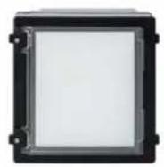
natural_image
Solid dark rectangular shape with no visible text, symbols, or features.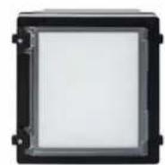

Bedienungsanleitung
Version 06/2021 (V1.2)
CE
natural_image
Blue square icon with a white telephone handset symbol (no text or numbers)
natural_image
Blue square icon with a white envelope symbol (no text or numbers)
natural_image
Blue square icon with a white eye symbol and corner brackets (no text or symbols)
natural_image
Blue square icon with a white lightning bolt symbol (no text or numbers)| Aufnahmeprotokolle |  | ||||
| 14-03 | |||||
| ABUSSecurity Tech Germany | ABUSSecurity Tech Germany |  | |||
| ABUSSecurity Tech Germany | ABUSSecurity Tech Germany |  | |||
| ABUSSecurity Tech Germany | ABUSSecurity Tech Germany | ||||
natural_image
Pure diagram of six rectangular frames arranged in a grid, no text or symbols presentAb Firmware V2.2.3 / V2.1.2 build 201029:
Remote Configuration
Configuring the Right and Password Parameters
Permission Password
Bis Firmware V2.0.8 / V2.1.2 build 200410:
Ab Firmware V2.2.3 / V2.1.2 build 201029:
Remote Configuration
Remote Configuration
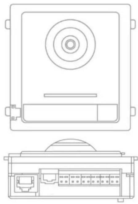
natural_image
Line drawing of a rectangular electronic device with concentric circles and a horizontal bar (no text or symbols)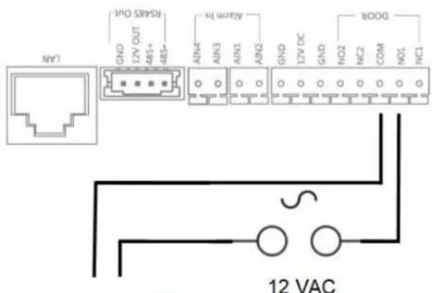

natural_image
Technical line drawing of a mechanical or electronic component with internal ports and a dome-shaped top (no text or symbols)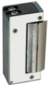
natural_image
Exterior view of a metallic industrial control unit with a vertical glass lid (no visible text or symbols)Max. 0,5 A @ 125 VA Max. 2,0 A @ 30 VDC
Remote Configuration


System

Device Information

General

Time

System Maintenance

User

RS485

Intercom

ID Configuration

Time Parameters

Permission Password

Zone Alarm

IP Camera Information

Volume input/Output

Ring Import

Deploy Info

Incoming Call Linkage

Relay

Network
Ring Configuration
| Index | Name | Size | Type | Add | Delete |
| 1 | Sprach...1_sd_2 | 185466 | wav | + | × |
| 2 | + | × | |||
| 3 | + | × | |||
| 4 | + | × |
Remote Configuration
| System |
| Device Information |
| General |
| Time |
| System Maintenance |
| User |
| RS485 |
| Intercom |
| ID Configuration |
| Time Parameters |
| Permission Password |
| Access and Elevator Control |
| IO Input/Output |
| Volume Input/Output |
| Dial |
| Motion Detection |
| Intercom Protocol |
| Sub Module |
| Network |
| Local Network Configuration |
| Linked Network Configuration |
| FTP Settings |
| Advanced Settings |
| Video Display |
| Video Parameters |
| Video Display |
| Video & Audio |
| CCD |
| Back Light Compensation |
TVHS20200, TVHS20210, TVHS20220":
| System |
| Device Information |
| General |
| Time |
| System Maintenance |
| User |
| RS485 |
| Intercom |
| ID Configuration |
| Time Parameters |
| Permission Password |
| Zone Alarm |
| IP Camera Information |
| Volume Input/Output |
| Ring Import |
| Deploy Info |
| Incoming Call Linkage |
| Relay |
| Network |
| Local Network Configuration |
| Linked Network Configuration |
| Advanced Settings |
| ABUS Link Station |
Streampfad: Streaming/Channels/101 (Main Stream)
Streaming/Channels/102 (Sub Stream)
Max. 2A @ 30 VDC
Max. 0.5A @ 125 VAC
natural_image
Technical line drawing of a device front panel and internal ports (no text or symbols)
Hutschienen Relais:
natural_image
Blue and silver mechanical component with no visible text or symbolsnatural_image
Close-up of a green electronic component with black and green terminals, no visible text or symbols.flowchart
graph TD
    A["Haupteingang / Main Entrance"] -->|2-Draft / 2-wire| B["TVH00150"]
    B -->|2| C["Nebeneingang 1 / Apartment 1"]
    B -->|2| D["Nebeneingang 2 / Apartment 2"]
    B -->|2| E["Nebeneingang 16 / Apartment 16"]
    C --> F["Apartment 1"]
    D --> G["Apartment 2"]
    E --> H["Apartment 16"]
    F --> I["WIFI A"]
    F --> J["ABUS Link Station Account A"]
    G --> K["WIFI B"]
    G --> L["ABUS Link Station Account B"]
    H --> M["WIFI P"]
    H --> N["ADUS Link Station Account P"]
    B -->|2| O["Info: 6 x TVH=203B.0"]
    D -->|2| P["Info: .3, .4, .5"]
    E -->|2| Q["Info: .3, .4, .5"]
    E --> R["Info: .3, .4, .5"]
natural_image
Solid dark rectangular shape with no visible text, symbols, or features.

User manual
Version 06/2021 (V1.2)
CE
English translation of the original German user manual. Retain for future reference.
EN Introduction
Dear Customer,
Thank you for purchasing this product.
TVHS20000 / TVHS20000S
The device complies with the requirements of the following EU directives: EMC Directive 2014/30/EU and the RoHS Directive 2011/65/EU.
TVHS20010 / TVHS20010(S)
The device complies with the requirements of the following EU directives: EMC Directive 2014/30/EU and the RoHS Directive 2011/65/EU.
TVHS20020 / TVHS20020(S)
The device complies with the requirements of the following EU directives: EMC Directive 2014/30/EU and the RoHS Directive 2011/65/EU.
TVHS20030 / TVHS20030S
The device complies with the requirements of the following EU directives: EMC Directive 2014/30/EU and the RoHS Directive 2011/65/EU.
TVHS20040
The device complies with the requirements of the following EU directives: EMC Directive 2014/30/EU and the RoHS Directive 2011/65/EU.
TVHS20200
ABUS Security-Center hereby declares that the device complies with Radio Equipment Directive (RED) 2014/53/EU. Additionally, these devices comply with the requirements of the following EU directives: EMC Directive 2014/30/EU and the RoHS Directive 2011/65/EU. The full EU Declaration of Conformity text can be found at the following internet addresses: www.abus.com/product/TVHS20200
TVHS20210
ABUS Security-Center hereby declares that the device complies with Radio Equipment Directive (RED) 2014/53/EU. Additionally, these devices comply with the requirements of the following EU directives: EMC Directive 2014/30/EU and the RoHS Directive 2011/65/EU. The full EU Declaration of Conformity text can be found at the following internet addresses: www.abus.com/product/TVHS20210
TVHS20220
ABUS Security-Center hereby declares that the device complies with Radio Equipment Directive (RED) 2014/53/EU. Additionally, these devices comply with the requirements of the following EU directives: EMC Directive 2014/30/EU and the RoHS Directive 2011/65/EU. The full EU Declaration of Conformity text can be found at the following internet addresses: www.abus.com/product/TVHS20220
TVHS10040 / TVHS20340
The device complies with the requirements of the following EU directives: EMC Directive 2014/30/EU and the RoHS Directive 2011/65/EU.
To ensure this remains the case and to guarantee safe operation, it is your obligation to observe these operating instructions.
Please read the entire user guide carefully before commissioning the product, and pay attention to all operating instructions and safety information.
All company names and product descriptions are trademarks of the corresponding owner. All rights reserved.
If you have any questions, please contact your specialist installation contractor or specialist dealer.

Disclaimer
This user guide has been produced with the greatest of care. Should you discover any missing information or inaccuracies, please let us know about them.
ABUS Security-Center GmbH & Co. KG does not accept any liability for technical and typographical errors, and reserves the right to make changes to the product and user manuals at any time and without prior warning.
ABUS Security-Center GmbH is not liable or responsible for any direct or indirect damage resulting from the installation, performance and use of this product. No guarantee is made for the contents of this document.
Important safety information
All guarantee claims are invalid in the event of damage caused by non-compliance with this user manual. We cannot be held liable for resulting damage.

We cannot be held liable for material or personal damage caused by improper operation or non-compliance with the safety information. All guarantee claims are void in such cases.
Dear customer,
The following safety information and hazard notes are not only intended to protect your health, but also to protect the device from damage. Please read the following points carefully:
- There are no components inside the product that require maintenance by the operator. Opening or dismantling the product invalidates the CE certification and guarantee claims/warranty.
- The product may be damaged if it is dropped, even from a low height.
Avoid the following adverse conditions during operation:
- Moisture or excess humidity
- Extreme heat or cold
- Direct sunlight
- Dust or flammable gases, vapours or solvents
- Strong vibrations
• Strong magnetic fields (e.g. next to machines or loudspeakers) - The camera must not be installed on unstable surfaces.
General safety information:
- Do not leave packaging material lying around. Plastic bags, sheeting, polystyrene packaging, etc. can pose a danger to children if played with.
- The video surveillance camera contains small parts which could be swallowed and must be kept out of the reach of children for safety reasons.
- Do not insert any objects into the device through the openings.
- Only use replacement devices and accessories that are approved by the manufacturer. Do not connect any non-compatible products.
- Please pay attention to the safety information and user manuals for the other connected devices.
- Check the device for damage before putting it into operation. Do not put the device into operation if you identify any damage.
- Adhere to the normal voltage limits specified in the technical data. Higher voltages could destroy the device and pose a health risk (electric shock).

When installing the device in an existing video surveillance system, ensure that all devices have been disconnected from the mains power circuit and low-voltage circuit.

If in doubt, have a specialist technician carry out assembly, installation and connection of the device. Improper or unprofessional work on the power supply system or domestic installation puts both you and other persons at risk.
Connect the installations so that the mains power circuit and low-voltage circuit always run separately
from each other. They should not be connected at any point or become connected as a result of a malfunction.
Contents
- INTENDED USE....84
- EXPLANATION OF SYMBOLS....84
- SYSTEM OVERVIEW 85
3.1 2- WIRE VARIANT....87
3.1.1 C COMPONENTS....87
3.1.2 R ECOMMENDED CABLE TYPES 88
3.2 IP NETWORK VARIANT 88
3.2.1 C COMPONENTS....88
3.3 I INSTALLATION COMPONENTS 89
3.4 S YSTEM VARIANTS 90
- START-UP 95
4.1 W IRING 95
4.1.1 I INSTALLATION HEIGHT 95
4.2 A CTIVATION OPTIONS / INITIAL PASSWORD ASSIGNMENT 96
4.2.1 A CTIVATION VIA DOOR STATION MONITOR 96
4.2.2 A CTIVATION VIA IP NETWORK.... 100
4.2.3 P PASSWORD RESET FOR MONITOR/VIDEO DOOR MODULE 100
- MONITOR OPERATION (2-WIRE & IP).... 101
5.1 L IVE IMAGE 101
5.2 M AIN PAGE OVERVIEW....102
5.2.1 M ENU ITEM: CALL SETTINGS 107
5.2.2 W I-FI SETTINGS 111
5.2.3 F LOOR BUTTONS.... 112
5.2.4 O THER SETTINGS.... 113
5.2.4.1 C ONFIGURATION - LOCAL INFORMATION.... 113
5.2.4.2 C ONFIGURATION – NETWORK SETTINGS 117
5.2.4.3 C ONFIGURATION - DEVICE MANAGEMENT 118
5.2.4.4 C ONFIGURATION - DEFAULT SETTINGS.... 120
5.2.5 R ELAY CONFIGURATION.... 120
5.2.6 MICROSD CARD 122
5.2.7 L OCK SCREEN....122
5.2.8 D EVICE INFORMATION 122
5.2.9 T IME SETTING 122
5.2.10 R ESTART DEVICE 122
5.2.11 P PASSWORD SETTINGS (PIN CODE).... 123
5.2.12 S YSTEM LANGUAGE.... 124
5.2.13 B RIGHTNESS SETTING 124
5.2.14 F LOOR BUTTON.... 124
5.2.15 O PEN SOURCE LICENCE INFORMATION.... 124
- MAINTENANCE AND CLEANING 125
6.1 FUNCTION TEST.... 125
6.2 CLEANING 125
- DISPOSAL....125
- OPEN SOURCE LICENCE INFORMATION 125
- INSTALLATION AND OPERATING INFORMATION.... 126
9.1 U SING THE SECURITY MODULE (TVHS10040).... 126
9.2 S ETTING UP BACK DOORS.... 128
9.3 S ETTING UP EXTENDED CALL BUTTONS (TVHS20020) FOR MULTI-FAMILY HOMES 129
9.4 A DJUSTING THE VOLUME ON THE DOOR VIDEO MODULE (TVHS20000(S), TVHS20010(S))..... 133
9.5 C ONNECTING AN EXISTING DOORBELL 134
9.6 C ONNECTING EXISTING DOOR OPENERS TO THE DOOR STATION MONITOR 134
9.7 C ONNECTING FLOOR CALL BUTTONS TO THE MAIN MONITOR 135
9.8 C ONNECTING ELECTRICAL DOOR OPENERS TO THE VIDEO MODULE (INCLUDING "GARDEN GATE")... 136
9.9 P LAYS YOUR OWN RING TONES IN THE DOOR STATION MONITOR 138
9.10 ABUS CMS: PERFORM FIRMWARE UPDATE FOR MODUVIS COMPONENTS.... 140
9.11 ABUS CMS: ADVANCED SETTING OPTIONS.... 142
9.12 MODUVIS AND ABUS LINK STATION APP RANGE OF FUNCTIONS.... 146
9.13 C OMPATIBILITY WITH ABUS PRODUCTS 146
9.14 C ONNECTING THE VIDEO DOOR MODULE TO ABUS NVR.... 146
9.15 "E MERGENCY DOOR OPENER" BUTTON ON DOOR VIDEO MODULE 147
9.16 R ELAY CONNECTION.... 149
9.17 I NSTRUCTIONS FOR MEASURING THE CURRENT DOOR OPENER.... 150
9.18 A PPLICATION EXAMPLE "VIDEO MODULE IN FRONT OF EVERY APARTMENT DOOR" 150
9.19 A PPLICATION EXAMPLE "INDIVIDUAL WIFI ACCESS" 153
- WIRING GUIDELINES (2-WIRE).... 154
1. Intended use
This MODUVIS door intercom is a two-way communication system with a video display of the door area. The system can be used for a single or multi-family home. With extension monitors in a living unit, the system can also be used as a two-way communication system (without video) within the home.
The MODUVIS door intercom is not a video surveillance system, nor may it be used as one.

Use of this product for any other purpose than that described may lead to damage to the product and other hazards. All other uses are not as intended and will result in the invalidation of the product guarantee and warranty. No liability can be accepted as a result. This also applies to any alterations or modifications made to the product.
Read the operating instructions fully and carefully before using the product. The operating instructions contain important information on installation and operation.
2. Explanation of symbols
The triangular high voltage symbol is used to warn of the risk of injury or health hazards, e.g. caused by electric shock.

The triangular warning symbol indicates important notes in this user guide which must be observed.

This symbol indicates special tips and notes on the operation of the unit.
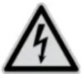
3. System overview
This door intercom is also available with two different wiring technologies:
2-wire variant: Communication and power supply are transmitted through 2 wires (1 pair). The wiring is star-shaped, with the central point a 2-wire distributor. A basic system consists of the 2-wire distributor, 2-wire monitor and 2-wire video module.
IP variant: Communication and power supply are transmitted through Ethernet (network) cables. The components support power over Ethernet (PoE) (optional 12 VDC) The wiring is star-shaped, with the (PoE) switch at the central point. A basic system consists of the IP monitor and IP video module.
flowchart
graph TD
    subgraph IP
        A["TVHS20200"] --> B["ITAC10100"]
        C["TVHS20000"] --> D["RJ45"]
        E["TVHS20210"] --> F["TVHS20300"]
        G["TVHS20010"] --> H["TVHS20100"]
        I["TVHS20210"] --> J["24VDC"]
    end
    subgraph 2-wire
        K["TVHS20210"] --> L["TVHS20300"]
        M["TVHS20010"] --> N["TVHS20100"]
        O["TVHS20210"] --> P["TVHS20300"]
        Q["TVHS20210"] --> R["TVHS20300"]
        S["TVHS20210"] --> T["TVHS20300"]
    end

Both system variants can be combined with one another. This allows for optimal adaptation to the building conditions present.
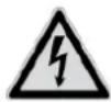
Examples of combined systems:
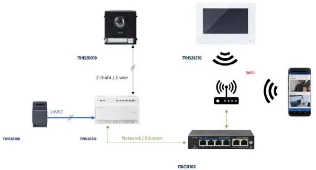
This example shows the mixed operation of a main monitor via 2-wire and an extension monitor via WiFi.
flowchart
graph TD
    A["TVHS20210"] -->|2-Draht / 2-wire| B["TVHS20310"]
    C["TVHS20010"] -->|2-Draht / 2-wire| B
    D["TVHS20210"] -->|WiFi| E["ITAC10100"]
    F["TVHS20310"] -->|24VDC| B
    G["Mobile Device"] -->|WiFi| E
    H["ITAC10100"] -->|Network / Ethernet| B
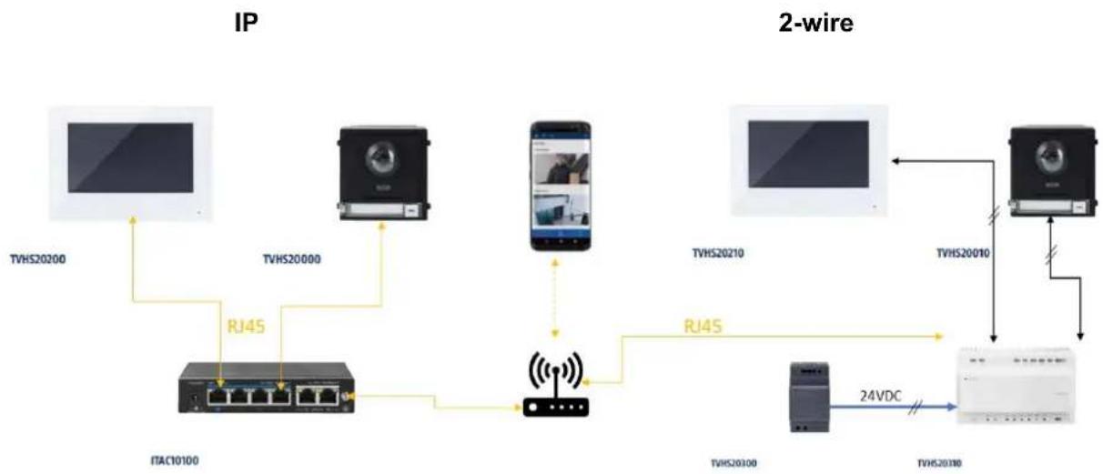
This example shows the mixed operation of a video door module via 2-wire with a main monitor via WiFi.
flowchart
graph TD
    A["TVH2010"] -->|2-Draht / 2-wire| B["ITAC10100"]
    C["TVH20210"] -->|WiFi| D["ITAC10100"]
    E["TVH20310"] -->|24VDC| B
    B -->|Network / Ethernet| F["ITAC10100"]
    G["Smartphone"] --> H["Mobile Device"]
3.1 2-wire variant
3.1.1 Components
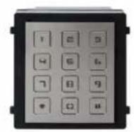
TVHS20210 2-wire monitor 2-wire monitor | TVHS20010 / TVHS20010S 2-wire video module 2-wire video module | TVHS20310 2-wire distributor 2-wire distributor |
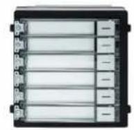
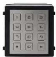
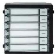
TVHS20020 / TVHS20020S Bell push button(6 buttons) Bell push button(6 buttons) | TVHS20030 / TVHS20030S Numeric keypad Numeric keypad | TVHS20040 Information module Information module |
TVHS20300 24 VDC power supply unit for hat rail 24 VDC power supply unit for hat rail | TVHS10040 / TVHS20340 Security module Security module |
3.1.2 Recommended cable types
Select the type of cable based on the distance between the video module, distributor and monitor.
2-wire video module (TVHS20010 / TVHS20010S)
2-wire monitor (TVHS20210)
2-wire distributor (TVHS20310)
| Cable type | 24AWG (10 Ω per 100m) | 20AWG (7 Ω per 100m) | 18AWG (4 Ω per 100m) |
| Cable length | |||
| TVHS20310 / TVHS20310 | Max. 60 m Max. | 60 m Max. 60 m | |
| TVHS20010(S) / TVHS20310 | Max. 35 m Max. | 60 m Max. 60 m | |
| TVHS20210 / TVHS20310 | Max. 35 m Max. | 60 m Max. 60 m |
3.2 IP network variant
3.2.1 Components
TVHS20200 / TVHS20220 IP 7"/10" PoE monitor IP 7"/10" PoE monitor | TVHS20000 / TVHS20000S IP video module IP video module | TVHS20020 / TVHS20020S Bell push button(6 buttons) Bell push button(6 buttons) |
TVHS20030 / TVHS20030S Numeric keypad Numeric keypad | TVHS20040 Information module Information module | TVHS10040 / TVHS20340 Security module Security module |
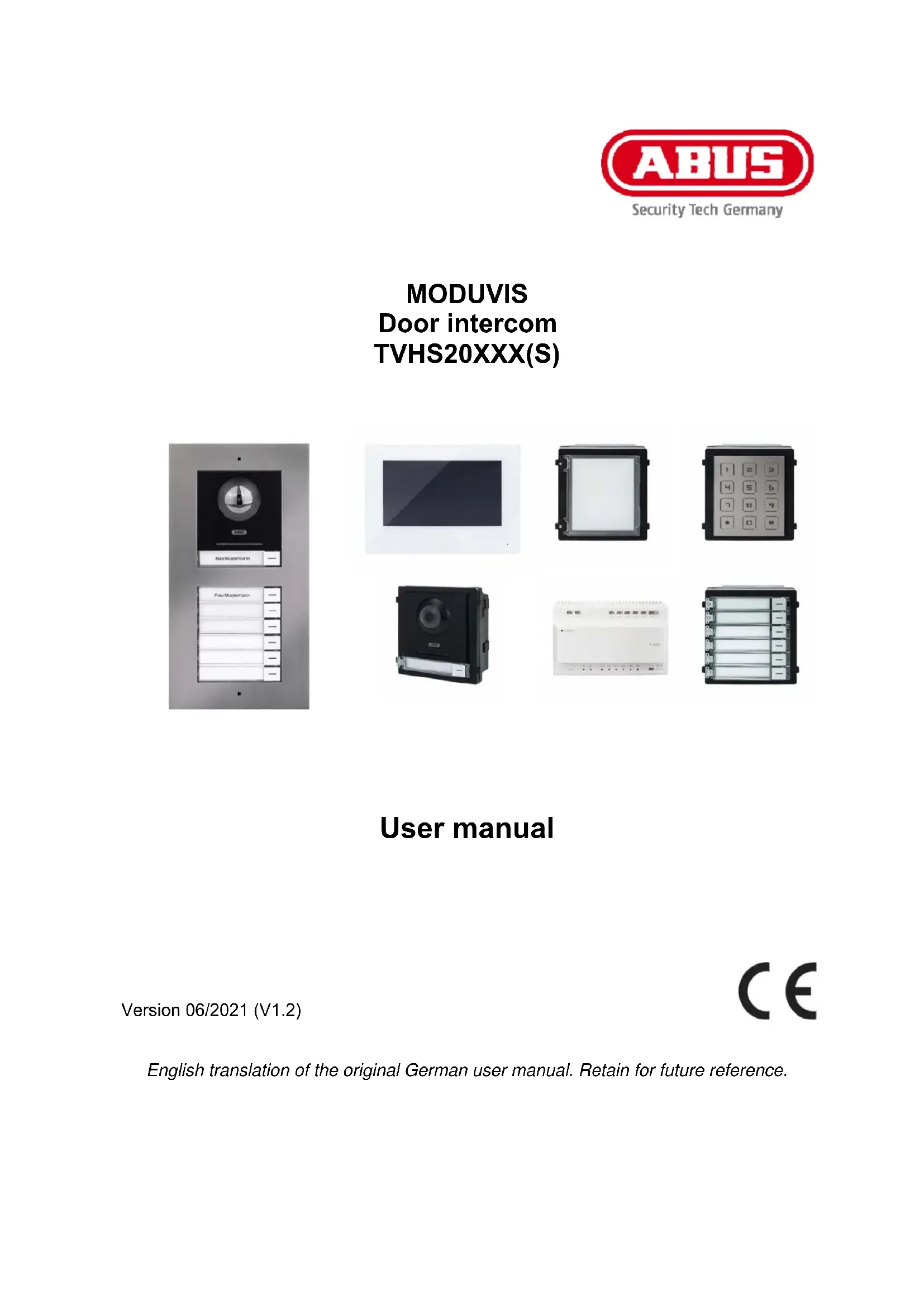
3.3 Installation components
These available installation components can be used for either the 2-wire or the IP variant of the Moduvis video door intercom
TVHS20050 Blank module aperture Blank module aperture | TVHS20060 Aperture for unused call button Aperture for unused call button | TVHS20100(S)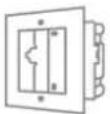 Frame for 1 module flush mounting Frame for 1 module flush mounting |
TVHS20110(S)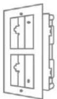 Frame for 2 modules flush mounting Frame for 2 modules flush mounting | TVHS20120(S)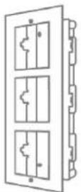 Frame for 3 modules flush mounting Frame for 3 modules flush mounting | TVHS10130(S)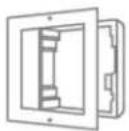 Frame for 1 module on-wall mounting Frame for 1 module on-wall mounting |
TVHS10140(S)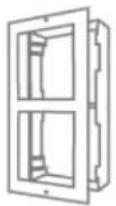 Frame for 2 modules on-wall mounting Frame for 2 modules on-wall mounting | TVHS10150(S)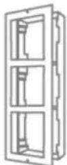 Frame for 3 modules on-wall mounting Frame for 3 modules on-wall mounting | TVHS20160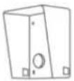 Outdoor housing for frame on-wall mounting (1 module) Outdoor housing for frame on-wall mounting (1 module) |
TVHS20170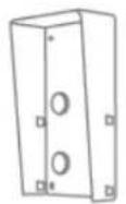 Outdoor housing for frame on-wall mounting (2 modules) Outdoor housing for frame on-wall mounting (2 modules) | TVHS20180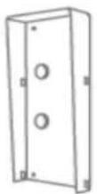 Outdoor housing for frame on-wall mounting (3 modules) Outdoor housing for frame on-wall mounting (3 modules) |
3.4 System variants
| # Technology / wiring | System configuration Application | example |
| 1 IP | 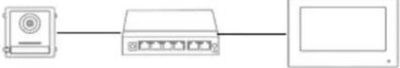 | Single-family home |
| 2 IP | 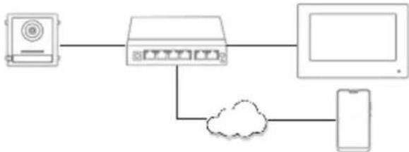 | Single-family home with app access |
| 3 IP | 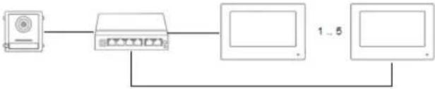 | Single-family home with interior extension monitors |
| 4 IP | 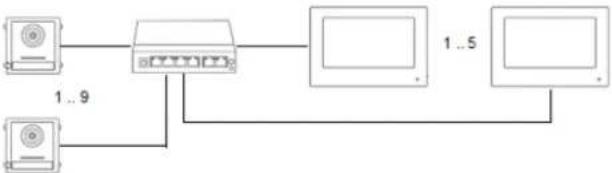 | Single-family home with interior extension monitors and back doors |
| 5 IP | 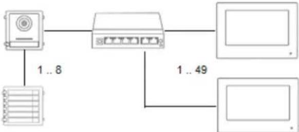 | Multiple dwelling house |
| 6 IP | 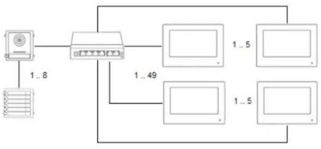 | Multi-family home with interior extension monitors |
| 7 IP | 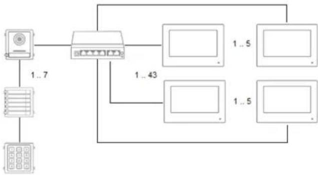 | Multi-family home with interior extension monitors and back doors |
| 8 IP | 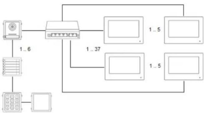 | Multi-family home with interior extension monitors, numeric keypad module and illuminated info module |
| 9 2-wire | 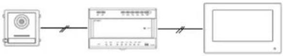 | Single-family home |
| 10 | Single family home with side entrance | |
| 11 2-wire | 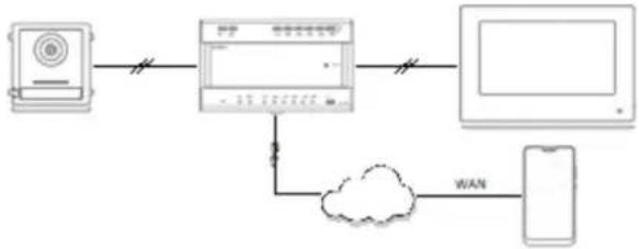 | Single-family home with app access |
12 2-wire Single-family 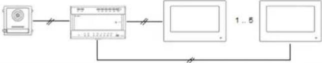 | home with interior extension monitors | |
| 13 2-wire | 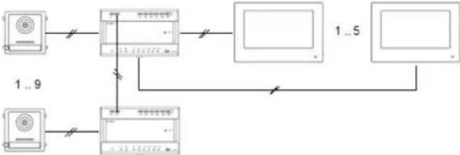 | Single-family home with interior extension monitors and back doors |
| 14 2-wire | 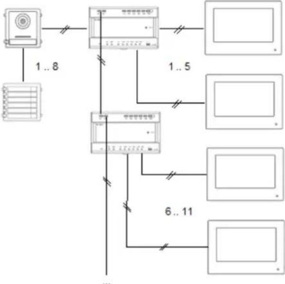 | Multiple dwelling house |
| 15 2-wire | 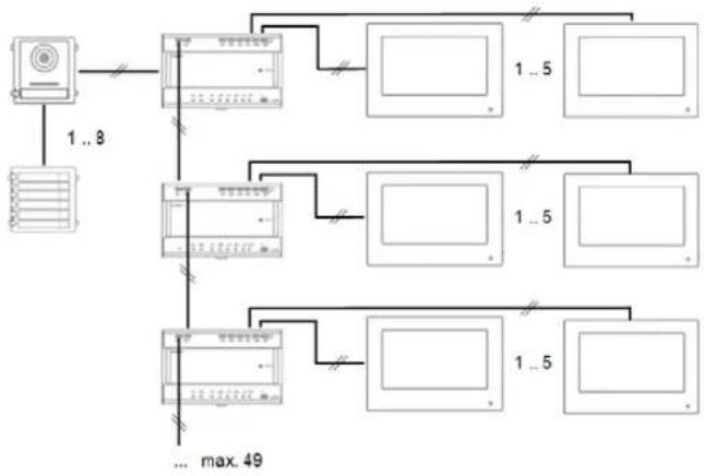 | Multi-family home with interior extension monitors |
| 16 2-wire | 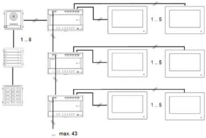 | Multi-family home with interior extension monitors and back doors |
| 17 2-wire | 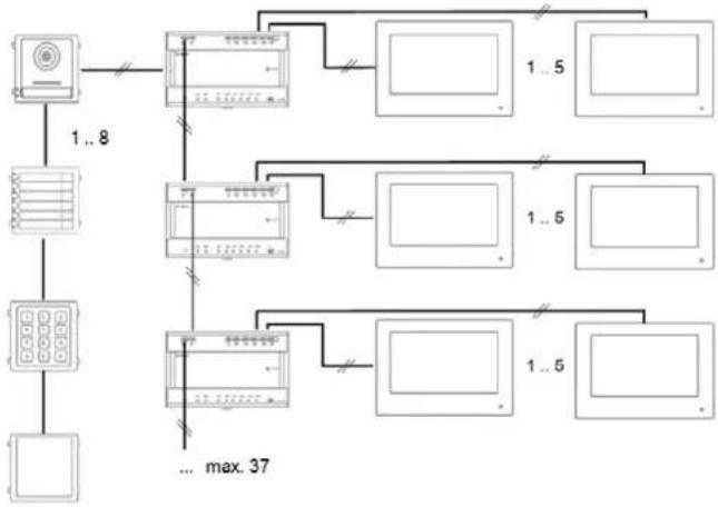 | Multi-family home with interior extension monitors, numeric keypad module and illuminated info module |
| 18 2-wire / IP | 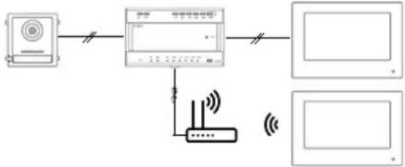 | Combination of 2-wire and IP technology:Interior extension monitor over WiFi connection |
 | NOTE:Each monitor and each door video module will appear separately in the network and have its own IP address. It makes no difference whether the systems are connected via PoE network or to the “2-wire distributor” in the 2-wire variant. The “TVHS20200” monitor can also be integrated into the network structure via WLAN. |
 | Note:Each terminal device must be connected directly to the distribution unit. Forwarding from one monitor to the next is not permitted. |
4. Start-up
4.1 Wiring
Please see the quick-start guide that comes with the product for more detailed wiring information. The brief instructions can also be found using the product search at www.abus-sc.de.
4.1.1 Installation height
The installation height of the video module TVHS20000(S) or TVHS20010(S) should not be less than 1.40 m (top edge). Otherwise it can happen that people standing too close to the video module cannot be recognized by their face.
4.2 Activation options / initial password assignment
4.2.1 Activation via door station monitor
1) Establish the system's power supply and make sure that the door station is also located in the same network.
Assign a password during initial monitor setup. This password will also automatically be used for door station activation. The password will also be required for the password-protected area of the monitor.
- 8-16 characters
- valid characters: numbers, lower-case letters, capital letters, special characters ( ! \$ % & / ( ) = ? + - )
- You must use at least two different types of character
2) Select the desired language and confirm by clicking "CONTINUE".
| < | Language assistant 1/4 |
| English | |
| Deutsch | |
| Italiano | |
| Francais | |
| Dutch | |

Firmware version note
Function: Dutch language
Video module (THVS20000(S) / TVHS20010(S)): V2.2.3_build_201029
Monitor (TVHS20200 / 210 / 220): V2.1.2_build_201029
3) Now choose between DHCP / Fixer IP address. It is highly encouraged to assign each separate device a fixed IP address, as otherwise new IP addresses may be assigned in the event of a power outage and this can cause serious disruptions in the system.
| Network assistant 2/4 | ||
| DHCP | ||
| Local IP 192.168.0.11 | ||
| Subnet mask | 255.255.255.0 |
| Gateway | 192.168.0.1 |
 | NoteWhen you press the switch for the DHCP function, the switch first jumps to the right and then to the left again.At this moment an IP address is obtained from the DHCP server, which is then set as a fixed IP address in the device. |
4) Select the type of monitor you wish to configure.
| Wizard assistant 3/4 | ||
| Indoor station Type Indoor station | > | |
| Floor 0 | ||
| Apartment no. 1 | ||
Indoor station:
The monitor acts as the main monitor for a home's door intercom system. It can be set up in a single-family or multi-family home. The main monitor in a residence must always be set up with the type "indoor station". If you only use one call button and one residence, the apartment number will remain on "1". If multiple residences/main monitors are used, the apartment numbers must be changed.
Example: Residence 1 => apartment number 1 Residence 2 => apartment number 2 (etc...)
This is the only way the call buttons can be assigned to different parties.
Note: A main monitor (indoor station) must always be linked to the main door station in the system.
Interior extension:
The monitor is used as an extension monitor in a system to equip more rooms in a home. All extension monitors are linked to the main monitor and display the same functions as the main monitor when the call button is pressed.
You can link up to a maximum of 5 additional monitors to a main monitors. (No. 1-5). You can also assign each monitor a "room name". The room names will automatically appear under "Contacts" on the other monitors in the system.
Note: An extension monitor (indoor station) must always be linked to the main monitor in the system.
The following menu items are not available on the monitor for the installation type “interior extension”. They can only be set/accessed on the system’s main monitor:
- Switch "automatic acceptance" for answering machine on/off.
- Listen to answering machine messages
- ABUS LINK Station App – menu
- Add network cameras
- Configure network address and set factory settings on end devices
5) "Assistant-connected devices"
| Assistant-releated devices | ||||
| Search by serial number | ||||
ABUS item no.  | IP address | Firmware version | Enable | |
ABUS item no.  | IP address | Firmware version | Enable | |
| ABUS item no. [IMAGE] | IP address | Firmware version | Enable | |
Here you can see the available network devices in the TVHS20xxx door station series.
The main door station must be selected here if you are setting up a main monitor. The main monitor must be selected here if you are setting up an extension monitor.
You can also “enable” the door station here. The main monitor will then automatically activate the door station with the same password used on the monitor.
Select the main door station from the list and click "Enable" to do this. After successful activation, please select the door station. A green confirmation tick will appear on the left side of the list. The door station is now activated and successfully linked.
If no device is found in the network, make sure that the door station is located in the same network and supplied with power.
Open the IP settings for the device by clicking the corresponding "cog". This allows you to change the IP address of the door video module.
If you would like to add other back doors, please turn to chapter "9.2 Setting up back doors" under Installation and operating information.
4.2.2 Activation via IP network
Install and start up the ABUS IP Installer (which is available for each respective product from the ABUS website www.abus.com).
Each connected device should now appear in the selection list without the relevant IP address for the target network, where appropriate.
Each device must first be enabled, i.e. a correspondingly secure password must be assigned for the main user "admin". A secure password must meet the following minimum requirements:
- 8–16 characters
- Valid characters: numbers, lower-case letters, capital letters, special characters ( ! \$ % & / () = ? + - )
- You must use at least two different types of character
The IP settings for the camera can be changed using the IP installer.
The “browser” button is not available for door intercom system components as they do not have their own web server.
Most programming for the components can be done on the door intercom system's monitor. For more complex system setup, however, you will need to use the CMS software for programming (connecting a component such as an IP device, open the menu item "remote configuration").

Activation in the IP network can also be done using the ABUS CMS software.
The ABUS CMS software may be necessary for certain other setup steps.
4.2.3 Password reset for monitor/video door module
To reset the password for monitors or video door modules, please contact our Technical Support.
5. Monitor operation (2-wire & IP)
5.1 Live image
| Button/display Description | |
 | Accepts the call and opens the video/voice connection. |
 | Ends a call and hangs up. |
 | Saves an instant snapshot of the current video image |
 | Opens the doors. If multiple relay outputs are used simultaneously, there will be up to 3 key symbols. (2x door relays in door video module, 1x door relay in monitor).For help connecting a door opener to the relay or using the security module TVHS10040, please see Installations and operating information in section“9.8 Connecting electrical door openers to the video module (including “garden gate”)” and“9.1 Using the security module (TVHS10040)” |
5.2 Main page overview
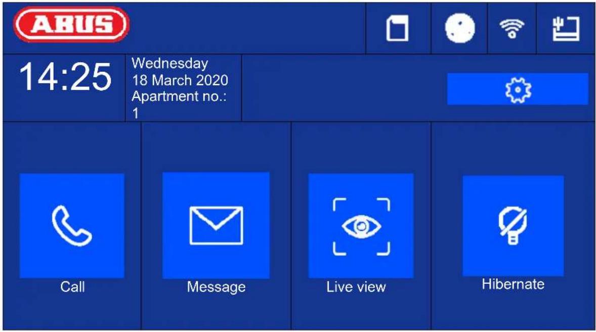
| Button/display Description | |
| Time Displays time | Typing in the display field will open the dialogue to set the date and time. |
| Day of week/date Current weekday display | Date display |
| Apartment number Display of configured apartment numbers for this indoor station.Up to 49 apartments per system possible. | |
| [Call] Set up intercom to indoor station or interior extension.Display/manage contactsView call log (including information about the door bell station, single frame, date, time) | |
| [Message] Information about notes, visitor notifications and single frames of the answer | |
| [Live View] Display live image of connected door stations and configured network cameras | |
| [Settings/cog] General call settings: Ring tone, ring duration, call duration, call re-routing, microphone volume, ring volume, conversation volume, key tone, auto accept, do not disturb modeWLAN settings for the monitor (only use for IP variant!)Other device settings: Configuration (system), relay behaviour, microSD card, time, screen brightness | |

natural_image
Blue square icon with a white telephone handset symbol (no text or numbers)
natural_image
Blue square icon with a white envelope symbol (no text or numbers)
natural_image
Blue square icon with a white eye symbol and corner brackets (no text or symbols)
natural_image
Blue square icon with a white prohibition symbol (no text or numbers)Call
Start calls between apartments or extension monitors. Contacts can also be created here. An interior extension is created automatically.
| *Enter phone number (0-0 for indoor station, 0-1 indoor station extension no. 1) | |||||
| 1 | 2 | 3 | - |  | |
| 4 | 5 | 6 | 0 | ||
| 7 | 8 | 9 |  | ||
Contacts
You can edit or delete created contacts here. To delete a contact, press and hold the contact row for 3 seconds. A menu will then appear with the option to delete contacts.
| Contacts |  |  | |
| Room 1 | |||
 | |||
 | |||
Call log
Displays the calls/door bells received. Can also directly access a snapshot.
 | Call log |  | ||
| Main door station |  | 14-03-2020 11:21:08 | ||
 | Main door station |  | 14-03-2020 10:55:37 |  |
 | Main door station |  | 14-03-2020 10:55:37 | |
 | Main door station |  | 14-03-2020 10:55:37 |  |
 | Main door station |  | 14-03-2020 10:55:37 | |
 | Main door station |  | 14-03-2020 10:55:37 | |
 | Main door station |  | 14-03-2020 09:55:37 | |
Note
 | Note |  | |
| No note | ... | ||
  | |||
Visitor notification (answering machine)
Audio messages left on the answering machine can be played here, if there are any and it is enabled.
| Visitor notification |  | ||
| No.1 | 14-03-202010:47:35 | ||
| No.2 | 13-03-202014:47:39 |  | |
| No.3 | 13-03-202014:26:06 | ||
 | |||
Recording log
Here you can find an overview of images sorted by day
| Recording log |  | ||||
| 14-03 | |||||
| ABUSSecurity Tech Germany | ABUSSecurity Tech Germany | ABUSSecurity Tech Germany | |||
| ABUSSecurity Tech Germany | ABUSSecurity Tech Germany | ABUSSecurity Tech Germany | |||
| ABUSSecurity Tech Germany | ABUSSecurity Tech Germany | ABUSSecurity Tech Germany | |||
5.2.1 Menu item: Call settings
| Call settings |  | ||||
| Door bell tone | Door bell tone 6 | > | |||
| Enable door bell tone |  |  | |||
| Door bell duration |  | 30 seconds |  | ||
| Call duration |  | 30 seconds |  |  | |
| Call re-routing |  | 0 s |  | ||
| Microphone volume |  | 10% |  | ||
| Door bell volume (monitor) |  | 70% |  | ||
| Conversation volume |  | 10% |  | ||
| Key tone |  | ||||
| Auto answer |  | ||||
| Auto Anwer Immediately |  | ||||
| Do not disturb mode | Indoor station | > | |||
| Do not disturb | All day | > | |||
| Button/display Description | |
| Door bell tone (1~6): Choose between 6 default door bell tones. | |
| Enable door bell tone: | You can enable or mute the door bell tone here. |
| Door bell tone (1~60s): Sets the door bell tone for an incoming call.After the set time, the door bell tone will automatically be muted. The call will still be active. | |
| Call duration (1~60s): | Sets the call duration. After the set time, the incoming call will automatically be ended. |
| Call re-routing (0~20s): Call re-routing delays the call to the ABUS LinkStation app.Example: 10 seconds. After a door bell call, | |
| the door station monitor rings immediately, but the ABUS Link Station is called with a delay of 10 seconds. | |
| Microphone volume (0~100%): | Set the monitor's microphone volume here.The higher the percent, the louder (and more sensitive) the monitor's microphone will be. |
| Door bell volume (monitor) (0~100%): Set the monito r's door bell volume here. | |
| Conversation volume (10~100%): | Set the desired conversation volume on the monitor here. |
| Key tone: Enables the key tone when typing on the monitor's touchscreen. | |
| Auto anser If the function is activated, the door intercom system accepts the call with the answering machine after the bell call has expired (ring duration). | |
| Auto Answer Immediately When the function is enabled, the door intercom immediately accepts a call with the answering machine.If the function is disabled, the answering machine will accept the call automatically after the set call duration. | |
| Do not disturb mode: Indoor station: | Allows calls from door stations and extension monitors. Calls from other apartments will not be allowed. To allow calls from apartments, please set the “do not disturb” function to “disabled”.All:All calls will be rejected. (Calls from door station, extension monitor or other apartment) |
| Do not disturb: Disabled, all day, time schedule (daily from/to hour/minute). Determines the time of day during which the “Do not disturb” function is active. | |

Firmware release note
Function: Auto Answer, Instant Auto Answer
Video module (THVS20000(S) / TVHS20010(S)): V2.2.3_build_201029
Monitor (TVHS20200 / 210 / 220): V2.1.2_build_201029
If you want to reuse an (already existing) door bell, turn to chapter "
9.5 Connecting an existing doorbell" in the section Installation and operating information. For information on changing the volume of the video door module, turn to chapter "
9.4 Adjusting the volume on the door video module (TVHS20000(S), TVHS20010(S)).
To record your own ring tones in the monitor, turn to chapter „9.9 Plays your own ring tones in the door station monitor“.
5.2.2 Wi-Fi settings
| Wi-Fi settings | |||
| MAX MUSTERWLAN | |||
| Button/display Description | |
| Arming/disarming | Enable/disable the Wi-Fi interface on the monitor |
| WiFi network list | You can find available Wi-Fi networks in your area here. By selecting an entry, you will be prompted to enter the Wi-Fi password. After connecting successfully, a green confirmation tick will appear in the list in front of the selected network. |
| Wi-Fi Info Icon | You can see the Wi-Fi parameters such as network name, signal level and IP parameters here.Click “Disconnect” to disconnect the monitor from Wi-Fi. |
5.2.3 Floor buttons
| Floor bell | |||
 | On/Off | ||
The floor button is connected directly to the monitor via the wired inputs and creates a direct door bell on the front door. This function is primarily used in multi-family homes. The main-door station is at the bottom of the main entrance here. Each home has a direct door bell button on the front door, however. The ring tone for the floor button is different from the normal ring tone of the video door module.
| Button/display Description | |
| Line 1 – Line 8 | Describes which input on the monitor is used for the floor button. Input 1 (line 1) is used as standard. |
| NO / NC | Normally Open / Normally Closed. This determines whether the call button on the front door is an open or closed contact. Typically it is a “NO” contact switch. |
Further information can be found in the Installation and operating information section in chapter "9.7 Connecting floor call buttons to the main monitor".
5.2.4 Other settings
5.2.4.1 Configuration – local information
| < | Local information |  | ||||
| Apartment no. | 1 | |||||
| Live image duration | 30 seconds |   | ||||
| ABUS Link Station service settings | > | |||||
| Synchronise time | > | |||||
| Summer Time | > |  | ||||
| Assistant | > | |||||
This area is password-protected. Please enter the password for initial setup.
Note: The following menu items are not available on the monitor for the installation type "interior extension". They can only be set/accessed on the system's main monitor:
- Switch "automatic acceptance" for answering machine on/off.
- Listen to answering machine messages
- ABUS LINK Station App – menu
- Add network cameras
- Configure network address and set factory settings on end devices
Installation type: Options: indoor station, interior extension
Indoor station: Main monitor for door intercom system in a home/apartment
Interior extension: up to 5 more monitors can be connected within a home/apartment
Example: Video module + indoor station + 5 interior extensions
natural_image
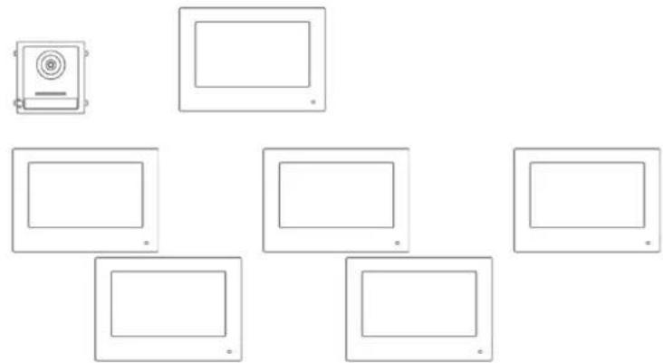
Pure diagram of six rectangular panels arranged in a grid, no text or symbols presentApartment no.: This is the maximum number of indoor station monitors that can be connected to a door video module with 8 call button extensions. This maximum number is 49 indoor station monitors or 49 homes/apartments.
Only for setting "Interior extension":
No. (1\~5): Number configuration for interior extension. A maximum of 5 extension monitors are possible.
Room name: Name for the room where the extension monitor is located.
Live image duration (10\~60s): Duration of the manually triggered live image display for a door video module or connected IP camera. (can be accessed via the main page/live image)
Information about setting up other call buttons in a multi-family home can be found in section Installations and operating information in chapter "9.3 Setting up extended call buttons (TVHS20020) for multi-family homes".
ABUS Link Station service settings:
The ABUS Link Station function helps make it easier to set up and connect a smartphone app to the door intercom system. It only takes a few steps. The door station must have an active internet connection in order to do this.
This menu only exists on monitors with the setting "Indoor station" (main monitor).
Enable this function if you would like to use the app to access the door intercom.
Procedure:
-
Install the ABUS Link Station APP (lite/pro) (Android/iOS)
-
Click "Add device" or "Scan QR Code" in the app.
3 Scan the QR code in the settings page for the ABUS Link Station service. Each indoor station monitor has its own QR code. - You will need to enter the verification code during the setup process. It is also on the setup page and can be changed as you like.
A QR code can only be added to an ABUS Link Station account. Other accounts can be granted access to the door intercom if approved.
| ABUS Link Station service settings | ||
| Activating ABUS Link Station service | ||
| Verification code | xxxxx | |
| ABUS Link Station server status | Connected | |
 | ||
Synchronise time: Enable time setting via the NTP protocol.
The interval determines the update frequency in minutes.
The field IP address allows an NTP server address or IP address to be entered.
The port number is fixed as 123 (standard port for NTP protocol.
Select the time zone in which the door intercom is located (generally GMT+01:00)
| Synchronise Time |  | |||
 Enable NTP Enable NTP | ||||
| Synchronise interval | 60 |  | ||
| IP address / Domain | ntp.org | |||
| Port no. | 123 |  | ||
| Time Zone | (GMT+1:00 Amsterdam, Berlin, Rome, Paris) | > | ||
 | ||||

When using the ABUS Link Station service in connection with the push function for a bell call, the NTP function must be activated and correctly configured.
Make sure to use the correct NTP server address "0.pool.ntp.org".
Summer time: Input details for changing between summer and standard time.
 | Summer Time |  | ||||
 | Enable DST | |||||
| Start time | Last week of March, Sunday 2:00 | > |  | |||
| End time | Last week of October, Sunday 3:00 | > | ||||
| Shift | 60min | > |  | |||
 | ||||||
Assistant: Restart the installation assistant. The following steps are performed
with the assistant:
a) Language setting
b) Network setting (wired interface)
c) Monitor installation type or mode (indoor station or interior extension) and apartment number
d) Device connection to monitor.
If indoor station-> assign a video module
If extension -> assign the main monitor
(indoor station)
5.2.4.2 Configuration – network settings
This menu primarily concerns the settings for the wired network interface
| Network settings |  | ||
| DHCP | |||
| Local IP | 192.168.0.11 |  | |
| Subnet Mask | 255.255.255.0 | ||
| Gateway | 192.168.0.1 |  | |
| DNS address | 192.168.0.1 | ||
| DNS address 2 | 194.25.2.129 |  | |
| Button/display Description | |
| DHCP Switch DHCP on/off. It is highly recommended to set all door intercom system components to a fixed IP. | |
| Local IP Set the device's local IP here | |
| Subnet Mask Set the device's subnet mask here | |
| Gateway Set the device's Gateway here. The router IP is generally used here. | |
| DNS address Set the device's DNS address here. The router IP is generally used here. | |
| DNS address 2 Set the device's alternative DNS address here. The router IP is generally used here. | |
5.2.4.3 Configuration – device management
Device Management
Main door station
192.168.0.26
The function of this menu is different for the indoor station and interior extension. You can change the device assignments here.
Attention:
The main monitor in a system must always be connected to the main video module.
An extension monitor in a system must always be linked to the main monitor in the system.
Indoor station: - Assigning the main door station
- Add other IP network cameras for a live view. To do this, click the “+” symbol at the top right and select “Private protocol” for an ABUS network camera.
Indoor extension: - Assigning the indoor station (main monitor)
The following interactions can also be carried out from this menu:
- Set network parameters (DHCP, IP address etc.) for door stations
- Reset door stations to factory settings
Setting the network parameters of the video door module
| Door Station Settings | |
| 192.168.0.26 | |
| 255.255.255.0 | |
| 192.168.0.1 | |
| DHCP |  |
| Microphone volume |  70% 70%  |
| Ring tone volume |  70% 70%  |
| Talk volume |  70% 70%  |
| Cancle OK | |
Lines 1 -3: IP address, gateway and subnet mask
DHCP: When the button is pressed, the request for the IP address data from the DHCP server is started. The switch then goes back to the left.
The received IP address data are then set as fixed data. There is no further automatic query of the data.
Microphone volume: Setting the sensitivity of the microphone in the video door module
Ring tone volume: Setting the volume of the ring tone after pressing the bell button on the video door module
Call volume: Setting the volume during a call on the video door module
Performing a reset to the factory settings of the video door module
All settings of the video door module can be reset here via the main monitor.
| Reset all settings to default? | |
| Cancle OK | |
To add an ABUS network camera to the system, please click the “+” symbol at the top right under “Add device”.
Select "Private protocol" for ABUS cameras and assign a device name of your choosing. The IP address of the camera in the network and the RTSP port (default 554) are also required for connection. Then you still need to enter the username and password for your network camera.
The list of compatible ABUS network cameras can be found at www.abus.com.
5.2.4.4 Configuration – default settings
Default settings:
Resets the monitor to default settings. It will still be activated and the password will remain the same.
Factory settings: Completely resets the monitor including password to factory settings. The monitor will then be in "inactive" status.
5.2.5 Relay configuration
 | Relay configuration | |||
 | Relay 1 |  | ||
| Duration |  | 3s |  | |
| Interval |  | 5s |  | |
| Relay 2 | ||||
Under “Relay configuration”, the two monitor relays themselves are configured. The configuration in this menu has no impact on the video door module relay.
The relay outputs are on the back of the monitor and can be connected via the enclosed splitter cable. The assignment is printed on the back of the monitor.
The relay 1 is switched between COM1 and NO1, relay 2 is connected to COM2 and NO2.
| Button/display Description | |
| Relay 1 Activates/deactivates the function | for an additional (or already existing) doorbell. The relay 1 on the monitor is triggered in parallel to a call. |
| Duration Determines how long the relay for the additional doorbell is triggered when pressed. | |
| Interval Determines the interval in which the relay is triggered for the set “duration” of the additional doorbell when pressed. | |
| Relay 2 Activates/deactivates the additional | switchingoutput on the monitor (e.g.: for a door opener on the front door of the respective floor). If the function is enabled, another “key symbol” labelled “3” will appear on the local monitor. |
For more information, read chapter "9.6 Connecting existing door openers to the door station monitor" and
“
9.5 Connecting an existing doorbell" in the section Installation and operating information.
You can also find information about the following topic here: "9.8 Connecting electrical door openers to the video module (including "garden gate")"
5.2.6 microSD card
| Button/display Description | |
| Format | Important: The complete micro SD card is formatted and all data on it will be erased. |
| uninstall, deinstall, uninstallation, deinstallation, uninstalling, deinstalling | Deactivates the microSD card, after which it will no longer continue to record. You can safely remove the microSD card. |
5.2.7 Lock screen
Locks the screen for 30 seconds. During this time, the touch panel will be disabled and can be cleaned, for example.
5.2.8 Device information
Here you can find the firmware version of the monitor as well as the model and serial number of your device. For update information, please turn to chapter "ABUS CMS software: Firmware Update" in section Installation and operating information.
5.2.9 Time setting
Here you can manually set the date and time on the monitor. Alternatively, you can also click directly on the time on the main screen.
5.2.10 Restart device
Restarts the monitor.
5.2.11 Password settings (PIN CODE)
PIN assignment for keypad TVHS20030
Password settings
Pin code
Note: You will need the keypad for PIN CODE entry TVHS20030 for this.
You can set a 6-digit key here that will then be used to open the doors via keypad. The PIN code is always 6 digits.
Please press the following combination to enter the PIN on the keypad:
Up to firmware V2.0.8 / V2.1.2 build 200410:
"#" 6-digit PIN "#". Example: # 123456 #
From firmware V2.2.3 / V2.1.2 build 201029:
"#" Apartment number 6-digit PIN "#". Example: # 1123456 #
- i.e. from this firmware the PIN can be set individually for each apartment.
- It is now possible to change and delete apartment-dependent PINs
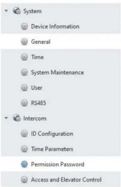
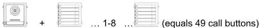
Locally on the monitor, one PIN CODE can be assigned. Three more codes can be entered using remote configuration with the ABUS CMS software. This means that a total of up to 4 PIN codes are possible. To add a code via ABUS CMS software, open remote configuration for the door video module and select the menu item "Intercom" and "Permission password". The PIN codes are generally saved in the video module and not in the keypad.
5.2.12 System language
Select your desired language.
Remote Configuration
5.2.13 Brightness setting
Here you can adjust the monitor's brightness from 0 - 100%.
5.2.14 Floor button
Activates/deactivates the floor button function. If the function is enabled, another menu item will appear on the right under the "Wi-Fi" symbol. The floor button function is now available and can be used via the monitor's wired inputs. Further clarification can be found under "9.7
Connecting floor call buttons to the main monitor" and "in the section Installation and operating information.
5.2.15 Open Source Licence information
Please read the Open Source Licence information at the end of this document.
6. Maintenance and cleaning
6.1 Function test
Regularly check the technical safety of the product, e.g. check the housing for damage.
If it appears to no longer be possible to operate the product safely, stop using it and secure it to prevent unintentional use.
It is likely that safe operation is no longer possible in the event that:
- the device shows signs of visible damage
• the device no longer works correctly
• the device has been stored in adverse conditions for a long period of time - the device has been exposed to stresses during transportation.

Please note:
You do not need to perform any maintenance on the product. There are no components requiring servicing or checking inside the product. Never open it.
6.2 Cleaning
Clean the product with a clean, dry cloth. The cloth can be dampened with lukewarm water to remove stubborn dirt.

Make sure that no liquids get into the apparatus and thereby destroy the device. Do not use any chemical cleaning products, as they could damage the surface of the housing.
7. Disposal

Devices displaying this symbol may not be disposed of with domestic waste. At the end of its lifespan, dispose of the product according to the applicable legal requirements.
Please contact your dealer or dispose of the products at the local collection point for electronic waste.
8. Open Source Licence information
The product contains software components that are licensed by the rights holders as free software or open source software (hereinafter referred to as "OSS"). The corresponding licenses are enclosed with the product in printed form and / or can be accessed via a graphical user interface. You can acquire usage rights to the extent regulated there directly from the rights holders. The open source licenses take precedence over all other license conditions and contractual agreements with ABUS in relation to the corresponding OSS software components contained in the product.
In general, license information on ABUS products can be called up at www.abus.com in the download area of the product description.
9. Installation and operating information
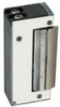
9.1 Using the security module (TVHS10040)
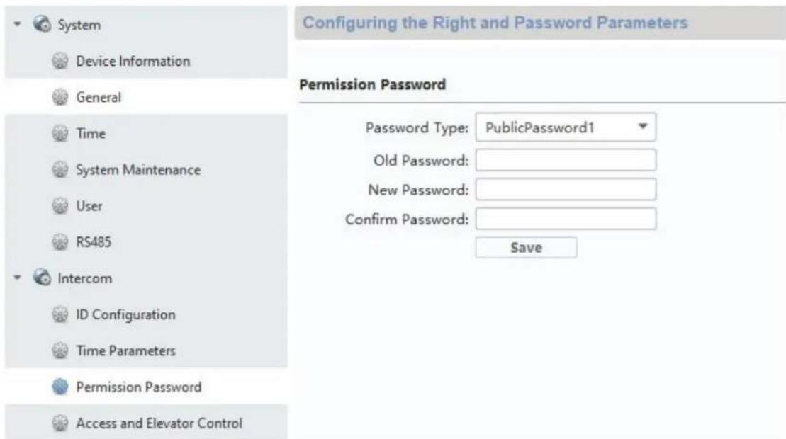
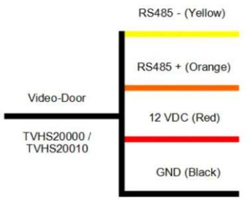
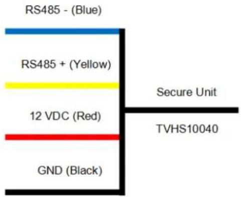
The security module TVHS10040 (new item number TVHS20340) serves to fit the door opener contact indoors under protection and thus prevent tampering. The security module is supplied with 12V voltage and clamped to the door video module by means of RS485-BUS.
Please use the enclosed 4-pin cable for the door video module. This cable must be isolated on one side of the connector and the cable must be connected to the security module. The ID DIP switches on the security module are not needed for this and will remain set to their default value. (DIP switch 1 on, DIP Schalter 2/3/4 off)
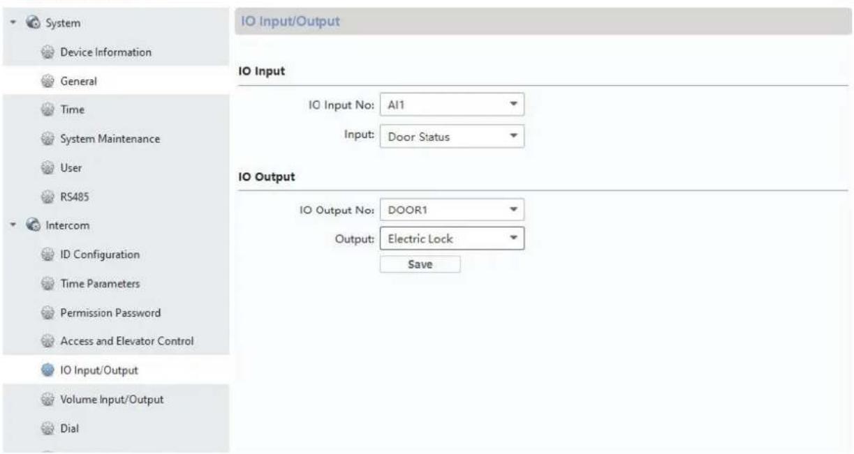
Up to firmware V2.0.8 / V2.1.2 build 200410:
The security module still has to be configured as a new door relay. To do this, open the remote configuration of the door video module with the ABUS CMS software and go to the "Intercom" / "IO In Out" menu and set "IO Out" for "DOOR 1" to "securityModule"
From firmware V2.2.3 / V2.1.2 build 201029:
After connecting the safety module, it is automatically recognized.
Now the relay security module will be triggered instead of the internal relay for the door video intercom module when the door is opened. While the relay is active, the green LED "Relay" will light up on TVHS10040.
Attention: Only one security module TVHS10040 / TVHS20340 may be used per video door module!
Note: The security module is always the last module connected, whether there is only a video door module or additional extension modules are connected.
Maximum relay load: max. 2A 30VDC / 0.5A 125AC
Remote Configuration
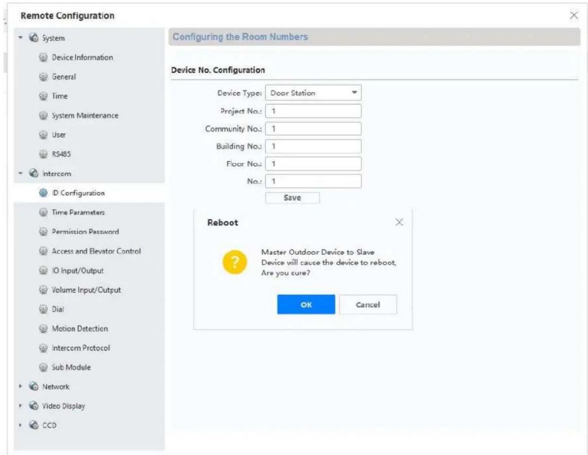
9.2 Setting up back doors
If you would like to integrate another door video module (maximum of 16) into the system to add a back door (e.g.: receiving goods, cellar doors etc.), follow these steps:
1) Connect the door video module for the back door to the network for the main door intercom station. All devices at the door intercom station must be located on the physical LAN.
2) Open the ABUS CMS software and activate the door module for the back door.
3) Add the door intercom module for the back door in ABUS CMS software and open remote configuration.
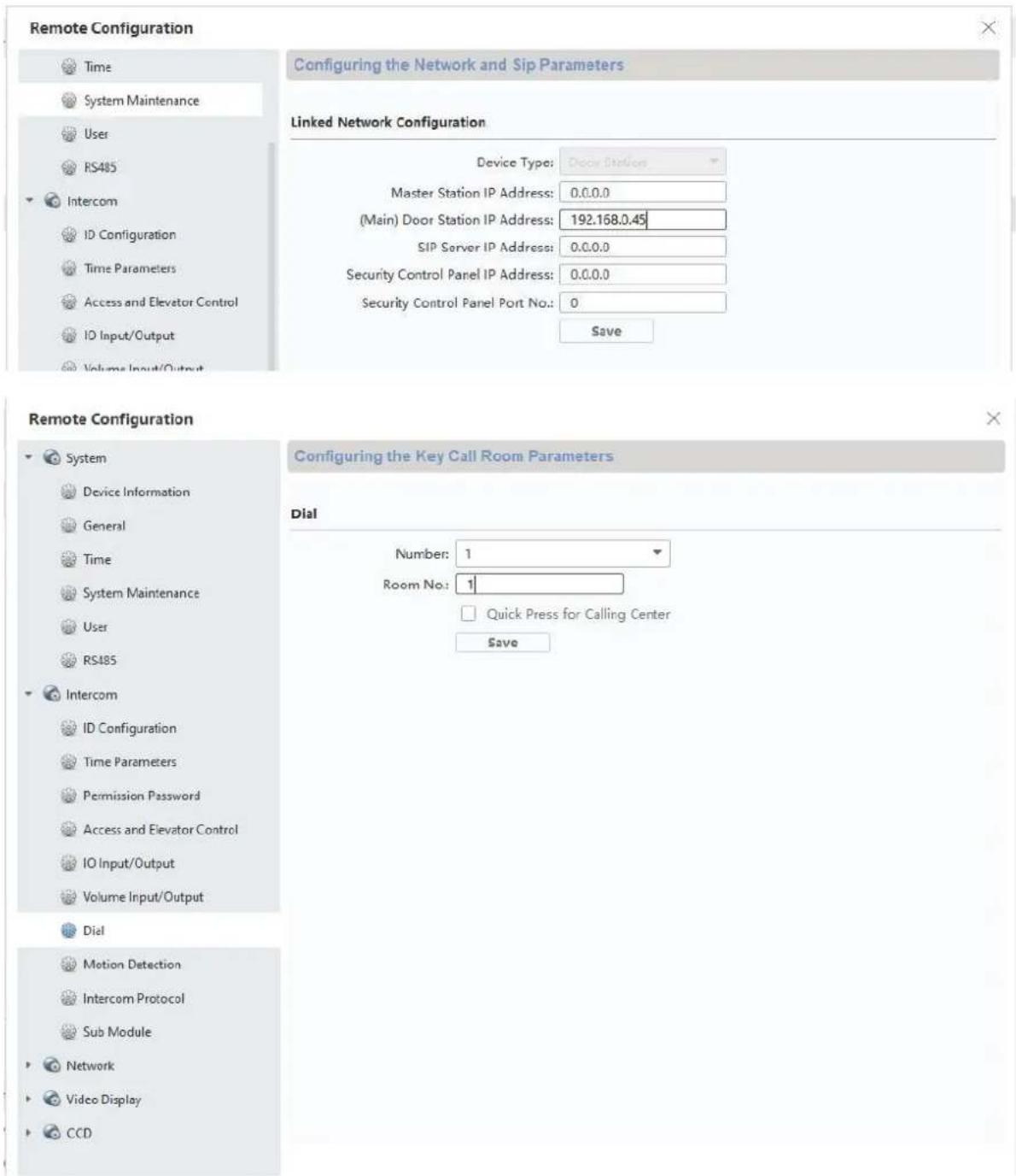
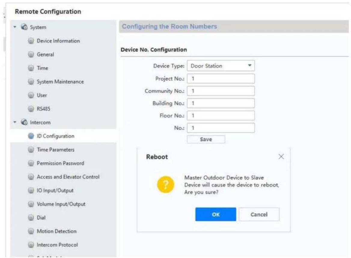
4) Now turn to "Room Number" under "Intercom". The numbers for the back door are entered under "No.:". The main door video module must have the number "0". The additional back doors will be numbered 1-9. Do not change the "Period/Building/Unit or Floor" numbers.
After savings, the system will restart. Confirm by pressing "OK".
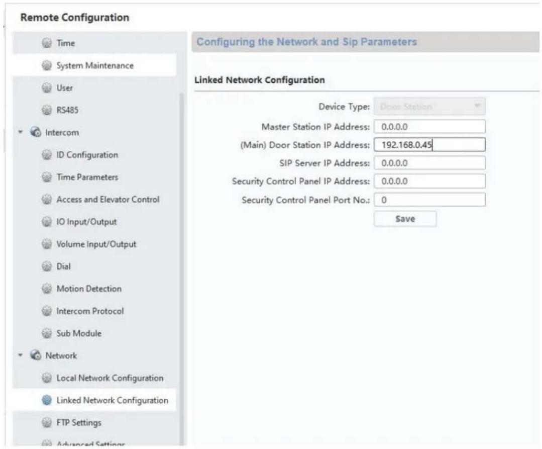
5) After successful restart, you will still need to assign the main doors for the back door. To do this, enter and save the IP address of the main door station under "Network" / "NetConfig SIP" under "(Main)Outdoor IP Address".
Attention: The menu “(Main) Outdoor IP Address” will only appear if you have properly completed step 4).
6) Setup for a back door is now complete. Now if a call button is pressed at the back door, the monitor will show that the call was started at a back door. Under "LIVE IMAGE" you can now directly access the video image of the back door on the monitor and open the doors.
9.3 Setting up extended call buttons (TVHS20020) for multi-family homes
Up to 49 call buttons can be used for multi-family homes via the additional module (TVHS20020(S)). The extension module is connected directly to the main video module via connecting cables.
If only one additional call button module is used, the installation can be done without the ABUS CMS software.
The main door module is by default the bell with "Apartment number 1". The extension module TVHS20020 is automatically set to apartment number 2–7. The "apartment" here corresponds to a separate residence.
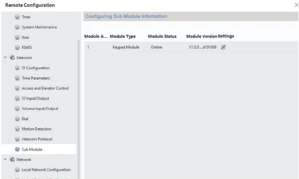
If you do not use the call button for the main video module and seal it with a cover plate, you will need to configure the extension module TVHS20020(S) via the ABUS CMS software. All extension modules connected to the RS-485 can be found under "Intercom" / "Submodules". (Exception: the security module TVHS10040/TVHS20340 does not appear here)
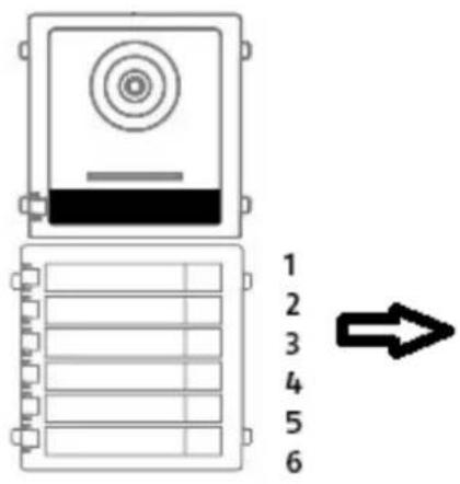
In the menu "Submode", click the "Settings" symbol to assign the apartment numbers.
The submodule ID is based on the ID set via DIP switch on the back of the extension module's housing. This allows you to easily make the proper assignments when setting up multiple extension modules.
Attention: After changing the ID via IP switch, the respective extension module must be briefly disconnected from the cable and restarted.
Remote Configuration


System

Device Information

General

Time

System Maintenance

User

RS485

Intercom

ID Configuration

Time Parameters

Permission Password

Access and Elevator Control

IO Input/Output

Volume Input/Output

Dial

Motion Detection

Intercom Protocol

Sub Module


Network
Configuring Sub Module Information
| Module Add... Module Type | Module Status | Module Version | Settings | |
| 1 | Nametag Module | Online | V1.0.0 ...d190522 | |
| 2 | Keypad Module | Online | V1.0.0 ...d191009 | |

Configuring the apartment number/residence number in the monitor:
In order to assign the call buttons in the residence to the correct monitors, the apartment numbers for the monitors must match the call button numbers.
The apartment numbers for the respective monitor are displayed in the monitor's main overview. You can either change the numbers directly in Configuration on the monitor (configuration/apartment no.) or access the respective monitor using ABUS CMS software and, in the menu "Intercom"/Room Number", change the apartment/residence numbers under "room.No.".
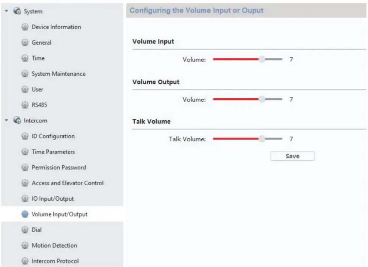
9.4 Adjusting the volume on the door video module (TVHS20000(S), TVHS20010(S))
Microphone sensitivity and voice volume on the door video volume can be adjusted using the ABUS CMS software. You can also set or fully disable the confirmation tones/call tones/busy signal volume.
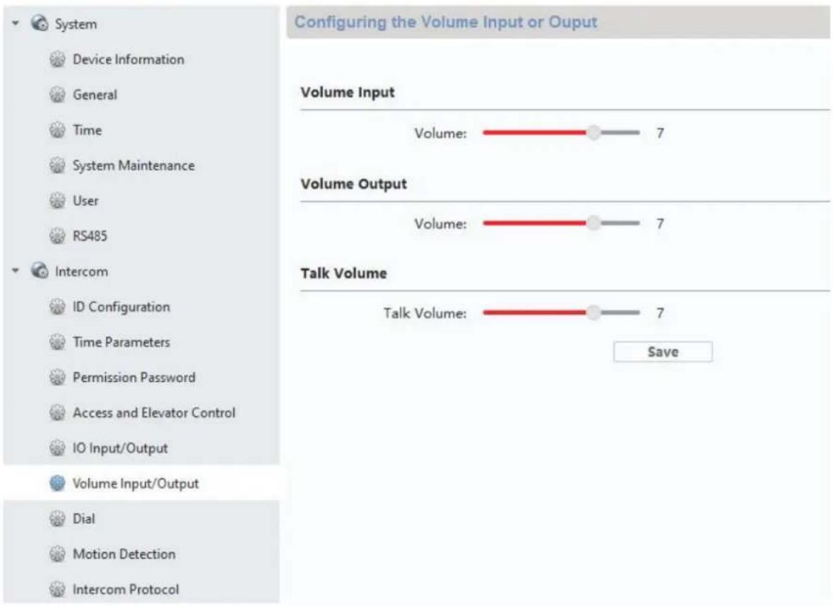
| Button/display Description | |
| Volume In Controls the microphone sensitivity for the door video module. The higher the value, the louder we will transmit voice to the monitor. | |
| Volume Out Controls automatic voice output (e.g.: leave a message, call failed etc. This controller can also be used to adjust the volume of confirmation tones/call tones and busy signals. (0 is completely mute) | |
| Talk Volume Voice volume is adjusted here. | The higher the value, the louder the voice will be transmitted from the monitor to the door station. |
Remote Configuration
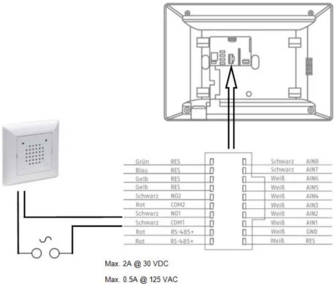
9.5 Connecting an existing doorbell
If you already have a doorbell, it can be connected to the relay output 1 (COM / NO I) on the monitor. The maximum relay load is 2A @ 30VDC or 0.5A @ 125AC.
If a call button is pressed, the relay will be switched at the desired interval and for the desired duration. The configuration for “Relay 1” can be found in the monitor’s menu under “Relay configuration”.
The relay, as well as the local ring tone on the monitor, will be triggered as long as is set under "Ring tone duration" in the "Call settings" menu.
If you only want to hear your external doorbell ring once, you can simply enable or disable the door bell tone on the monitor in the "Call settings" in the "Enable door bell tone" menu.
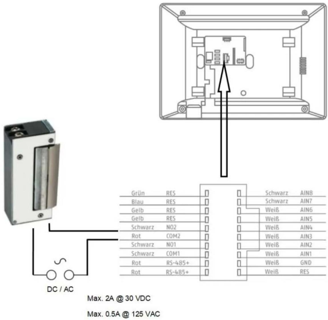
9.6 Connecting existing door openers to the door station monitor
To open a front door separately from a main entrance door, the monitor offers the option to control another door via a relay output (relay 2). The maximum relay load is 2A 30VDC or 0.5A 125AC.
To use the relay on the monitor, please enable "relay 2" under "relay configuration" in the monitor menu. Now another "key" symbol labelled "3" will appear in the monitor. Labels "1" and "2" are reserved for the door video module relays.
Relay "3" on the monitor can only be switched directly via the monitor, and not via the ABUS LINK STATION app.
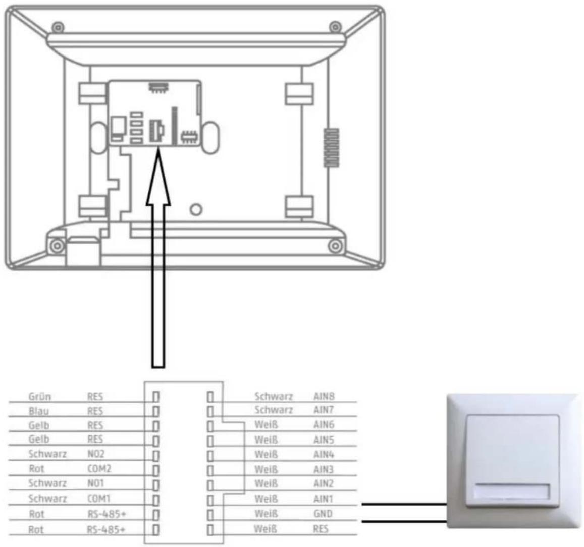
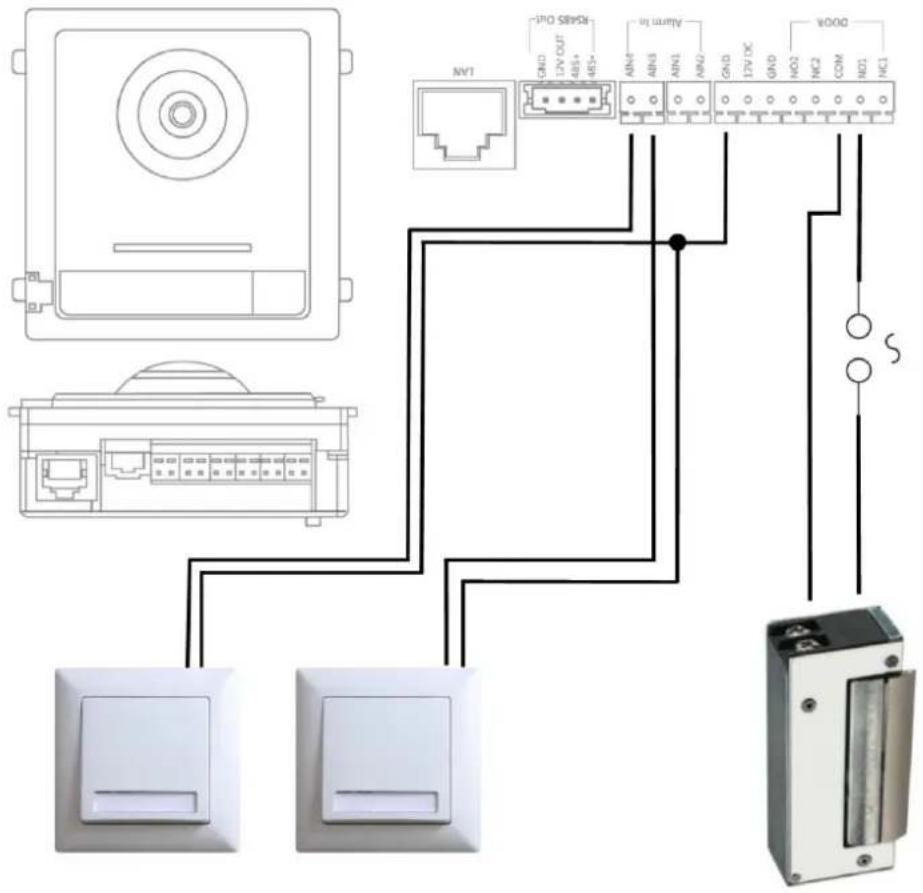
9.7 Connecting floor call buttons to the main monitor
The floor button (call button directly on the front door of a multi-family home) can be connected directly to the monitor. Directly wired to alarm input 1, the monitor can emit a bell signal and signal to the customer that someone has rung the upper front door.
Note: The floor button ring tone cannot be changed. It is different from the call button on the door video module so that it is obvious where the call originated. The floor button does not trigger an interaction on the monitor. Only a short ring tone will sound.
9.8 Connecting electrical door openers to the video module (including "garden gate")
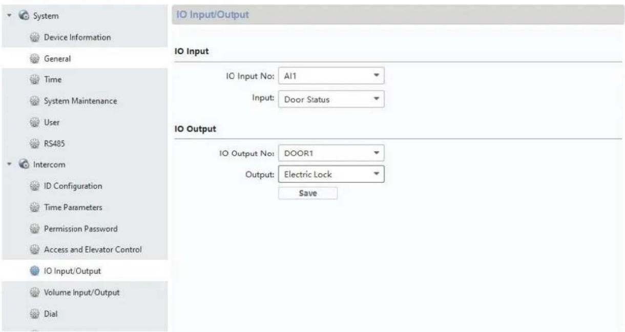
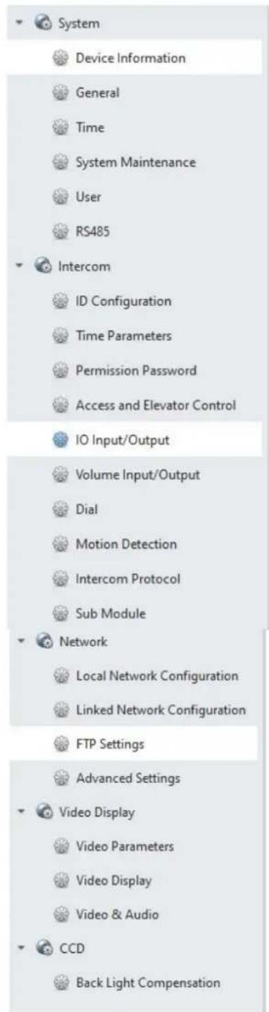
2 independent relays can be switched on the door video module and used to e.g.: open doors. To configur the relays, open remote configuration for the door video module with the ABUS CMS software and go to the menu "Intercom" / "IO In Out".
The respective relays for DOOR 1 and DOOR 2 can be configured under "IO out" or disabled if necessary. If the relay is disabled, the "key" symbol to open the door will not in the ABUS Link Station app or on the monitor.
Note: Only one of the two relays may be on "securityModule" (security module TVHS10040).
| Button/display Description | |
| Disable The relay is not used and hidden from view | |
| electricLock The internal relay for the door video module is used | |
| securityModule The external security module | TVHS10040 is used. (See menu item “security module”) |
natural_image
Technical line drawing of a device rear panel and internal connector housing (no text or symbols)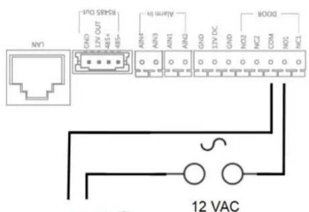
natural_image
Exterior view of a rectangular electronic device with a metallic panel and mounting holes (no visible text or symbols)Max. 0,5 A @ 125 VA Max. 2,0 A @ 30 VDC
9.9 Plays your own ring tones in the door station monitor
You can load your own ring tones in *wav format to your monitor using the ABUS CMS software. To do this, open remote configuration for the respective monitor and go to "Intercom" in the "Ring import" menu. Select an open slot here and upload the *WAV audio file. Once it has successfully uploaded, the file will be available under "ring tones" directly on the monitor.
Attention: A ring tone selected in the monitor cannot be erased using ABUS CMS. First select another ring tone in the monitor and then try again to erase the ring tone in CMS.
The WAV file must fit the following parameters:
Format: wav;
Maximale size: ≥300Kb;
Bit rate: 8KHz;
Channel: Mono
Bit rate: 128Kbps
Remote Configuration

System
Device Information
General
Time
System Maintenance
User
RS485
intercom
ID Configuration
Time Parameters
Permission Password
Zone Alarm
IP Camera Information
Volume Input/Output
Ring Import
Deploy Info
Incoming Call Linkage
Relay
Network
Ring Configuration
| Index | Name | Size | Type | Add | Delete |
| 1 | Sprach...1_sd_2 | 185466 | wav | + | × |
| 2 | + | × | |||
| 3 | + | × | |||
| 4 | + | × |
9.10 ABUS CMS: Perform firmware update for Moduvis components
Attention: Never disconnect the power supply or network cable during an upgrade
Attention: Only perform the update in a stable network environment (LAN).
We recommend setting each device to factory settings after a firmware update.
The ABUS CMS software is required to upload a firmware update to a monitor or the video door. Connect the devices to the network and open the remote configuration for the respective devices.
Go under "Maintenance" / "System Maintenance" and select the corresponding file for the device.
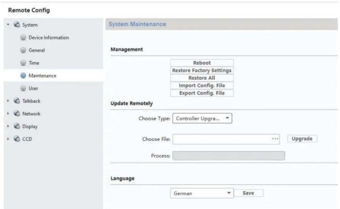
"Controller upgrade" must be selected when updating a door video module (TVHS20000(S), TVHS20010(S)).
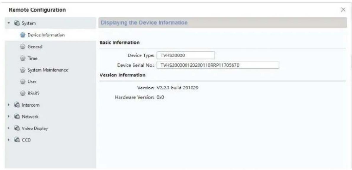
The current firmware version can be determined using ABUS IP Installer or in the CMS software in the respective device configuration under "Device Information".

After a firmware update, the following steps must be carried out:
- Restart the entire system by removing the supply voltage
- Reset all updated devices to factory settings ("Restore all")
9.11 ABUS CMS: Advanced setting options
Below is a brief overview of the setting options via remote configuration with the ABUS CMS software.
Each monitor and each door video module will appear in the network as a separate network device, regardless of whether the device is connected via 2-wire or PoE.
Remote settings for TVHS20000(S), TVHS20010(S), video door module:
Remote Configuration
| “System” section | |
| Device Information | General information about firmware, serial number |
| General Device | name and device ID (not relevant for door intercom system) |
| Time Settings for date/time, summer time and NTP server | |
| Maintenance Maintenance menu for firmware update, set factory settings and restart device | |
| User Menu is not used | |
| RS485 Menu is not used | |
| “Intercom” section | |
| ID Configuration | “Device type” must always be on “Outdoor unit”. Please do not change any numbers for the units “Period, Building, Unit, Floor” as these values are not needed here. Back doors are set up under “No.”. 0 = main doors, “1” – “9” = back doors. Please consult the chapter “Setting up back doors”. (See Installation and operating information) |
| Time Parameters | Max talk time: Maximum conversation duration for an accepted call. (90-120s)Max Msg time: Recording time for answering machine (30-60s) |
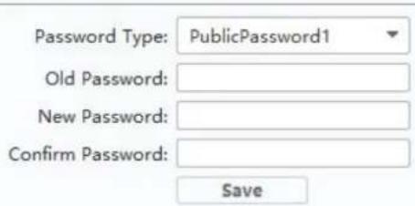
| Permission Password | 3 additional PIN codes (6-digit) can be set here to use in combination with TVHS20030. |
| Access and Elevator Control | Door. No.: Select between relay output 1 and 2.Open door time: Determines how long the relay should engage the door opener. (1-255s)“Door name” and “Card encrypt” not used. |
| IO Input/Output | Settings for digital inputs (for emergency door opener) and the relay for door opener. |
| Volume Input / Output | Audio parameter settings for video door module. (See Installation and operating information) |
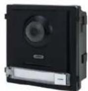
| Dial | Determines the apartment assignment for the call button on the door video module itself. A “1” will be under “room no.” as standard from the factory. This means the monitor is called with apartment number 1. |
| Motion Detection | Motion detection setting in connection with ABUS NVR. (Please only set up and configure the motion detection directly via ABUS NVR) |
| Intercom Protocol | Not used |
| Sub Module Overview of connected extension modules e.g.: TVHS20020, TVHS20030, TVHS20040 | |
| “Network” section | |
| Local NetCfg IP address of video door module. (IP address, subnet mask, standard gateway)Port: 8000 is needed to connect to an ABUS NVRhttp Port is not needed as there is no web interface | |
| Linked Network Configuration | Menu item is not used on a main video door module.Main Outdoor IP Address: Is used to assign the main door station to a back door. (See Installation and operating information) |
| FTP Configuration | Not used |
| Advanced Settings | Configuration of DNS server address for door video module |
| “Display” section | |
| Video Parameter | Settings for image parameters (brightness, contrast, saturation) |
| Video Display Settings for OSD display (camera name, date, time, text position) | |
| Video&Audio Stream parameter settings for video door module camera.Attention: We do not recommend modifying settings. | |
| Back Light Compensation | BLC function options for compensating for back light. |
| System |
| Device Information |
| General |
| Time |
| System Maintenance |
| User |
| RS485 |
| Intercom |
| ID Configuration |
| Time Parameters |
| Permission Password |
| Zone Alarm |
| IP Camera Information |
| Volume Input/Output |
| Ring Import |
| Deploy Info |
| Incoming Call Linkage |
| Relay |
| Network |
| Local Network Configuration |
| Linked Network Configuration |
| Advanced Settings |
| ABUS Link Station |
| Device Information | Information such as “firmware”, “serial number” etc. |
| General Device | name and device ID (not relevant for door intercom system) |
| Time Settings for date/time, summer time and NTP server | |
| Maintenance Maintenance menu for firmware update, set factory settings and restart device | |
| User Not used | |
| RS485 Not used | |
| “Intercom” section | |
| ID Configuration | Selection of apartment numbers in “Indoor station” mode (main monitor)In “Station Extension” mode (extension monitors), the number of the extension monitor is configured.Note: The “main monitor” or “extension monitor” mode is typically selected and the numbers assigned through the menu on the respective monitors. (e.g.: In setup process via installation wizard) |
| Time Parameters | Settings for call duration, live image display time, call forwarding delay, ring tone duration.Note: These settings can also be changed directly in the monitor’s menu. |
| Permission Password | Is not used in the monitor’s remote configuration. |
| Zone Alarm Not used | |
| IP camera information | Add ABUS network cameras. (See compatibility list) Up to 16 ABUS network cameras can be added and watched live. (Camera cannot be played back or configured directly from the door station) |
| Volume Input/ Output | (See Installation and operating information) |
| Ring Import Manage own ring tones (See Installation and operating information) | |
| Deploy Info Not used | |
| Incoming Call Linkage | Not used |
| Relay | Not used |
| “Network” section | |
| Local NetCfg Monitor IP address. (IP address, subnet mask, standard gateway) | |
| Port: 8000 is not needed herehttp Port is not needed as there is no web interface | |
| Linked Network Configuration | Assign the main monitor and the main door video module. The IP address of the main door module is entered here in the case of a main monitor.The entry “MainOutdoorUnit” may not be changed.Note: The door video module is typically already assigned to the monitor when setting up locally on the monitor itself. |
| Advanced Settings | Configuring monitor’s DNS server. |
| ABUS Link Station | Configure access via ABUS Link Station App.See ABUS settingsLink Station service.Connection to the ABUS Link Station app can simply be done via the interface on the monitor itself. |
9.12 MODUVIS and ABUS Link Station app range of functions
The MODUVIS door intercom can be integrated into the ABUS Link Station app. The following options are available:
Change verification code: The verification code should first be changed in the menu item "ABUS Link Station Service". Click on the code currently displayed to do this.
Add: Scan the QR code and add the device to the app. You still need to enter the verification code.
Share device: The door intercom can be shared with other users. This allows multiple people or apps to access the system.
Push options: The ABUS Link Station app will be called immediately or on a delay when someone rings the door intercom. The call can be accepted on the app and two-way audio with video of the door station is possible. Video may be disabled with voice-only if reception quality or mobile bandwidth is limited.
Door open: relay 1 or relay 2 can be switched in the app. This allows electrical door openers, for example, to be controlled.
Event log: The app has a notification page with entries from the most recent door bell activity with a picture of the event.
9.13 Compatibility with ABUS products
This section addresses possible interaction with other ABUS products.
| ABUS product Compatibility | |
| Secvest No | |
| WAppLoxx Relay connection | |
| WAppLoxx Pro Relay connection | |
| ABUS IP cameras | See compatibility listwww.abus.com,www.abus-sc.de |
| ABUS NVR For integrating the door station video, see section 9.14 | |
| ABUS Link Station APP Access live image from door stationPush notification when bell rings | |
9.14 Connecting the video door module to ABUS NVR
The video image from the video door module can also be integrated into an ABUS NVR. The video is tapped using the RTSP protocol, which only enables permanent display or permanent recording (no motion detection or other types of event recording).

Please note the data protection regulations prevailing at the installation site!
The following steps are necessary for the integration:
- Creation of a user-defined protocol in the camera management of the ABUS NVR.
- The following stream details are to be used:
Protocol: RTSP
Transfer protocol: Automatic
Port: 554 (standard port)
Stream path: Streaming / Channels / 101 (Main Stream)
Streaming / Channels / 102 (Sub Stream)
- When adding a new channel to the NVR, this custom protocol will be selected for the video door module.
Username ("admin") and password are usually the same as the door station monitor. If the password was changed via the CMS software, this changed password must be used.
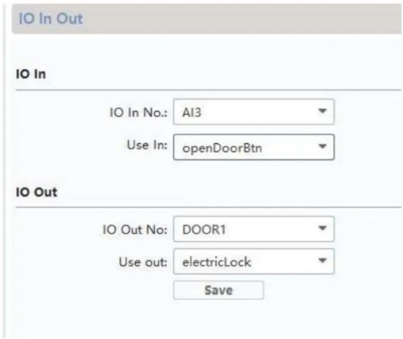
9.15 "Emergency door opener" button on door video module
A button/switch can be attached directly to the door video module via alarm input 3 (AIN 3 = relay 1) and alarm input 4 (AIN 4 = relay 2), which actuates when the door relay is engaged.
To enable alarm input 3 (AI3 and AI4), open the remote configuration for the respective door video module with the ABUS CMS software and set AI3 to "openDoorBtn"
The AIN3 for the door video module now opens the relay 1 door The AIN4 for the door video module now opens the relay 2 door
For security reasons, this function is disabled when the system is delivered.
Max. 2A @ 30 VDC
Max. 0.5A @ 125 VAC
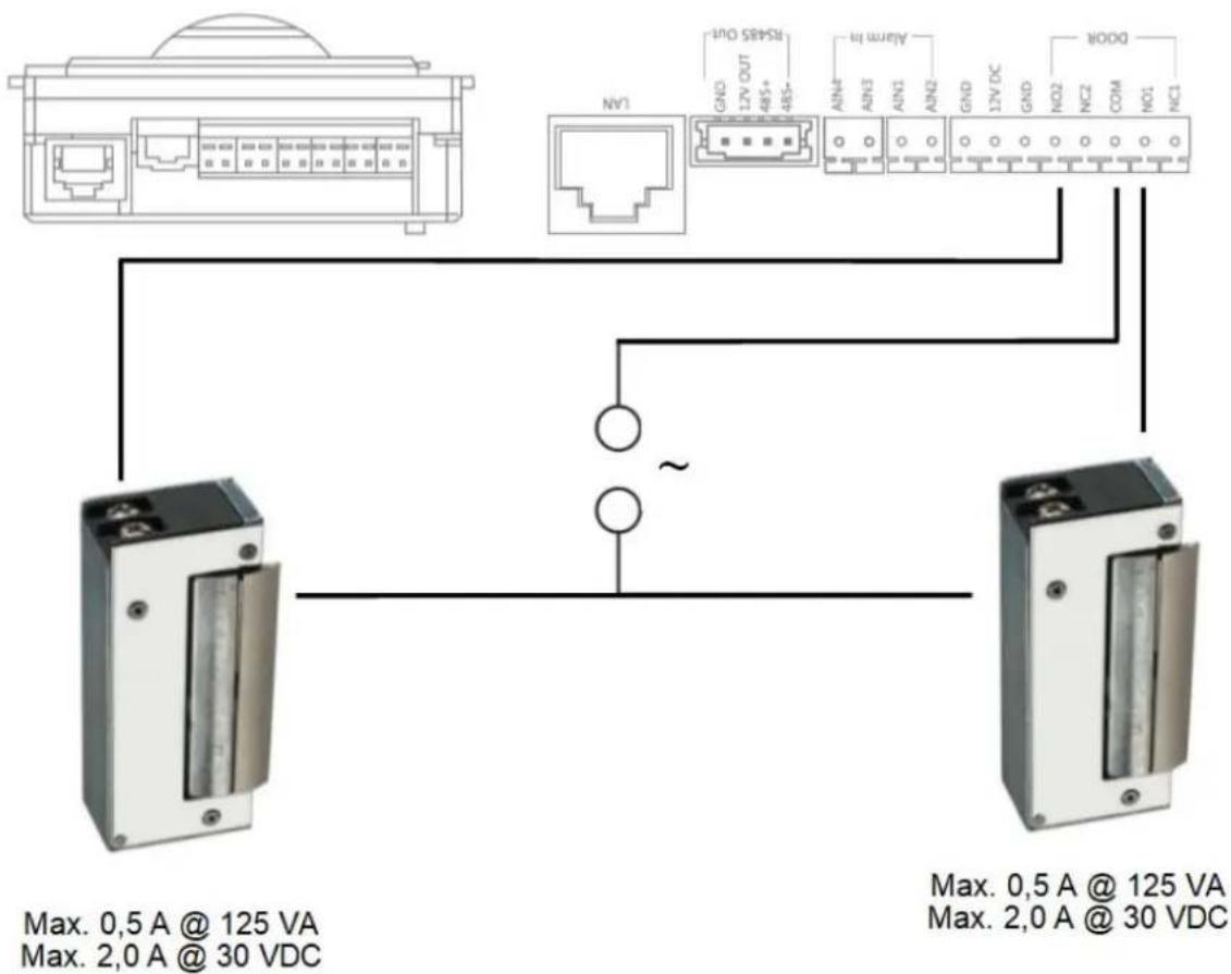
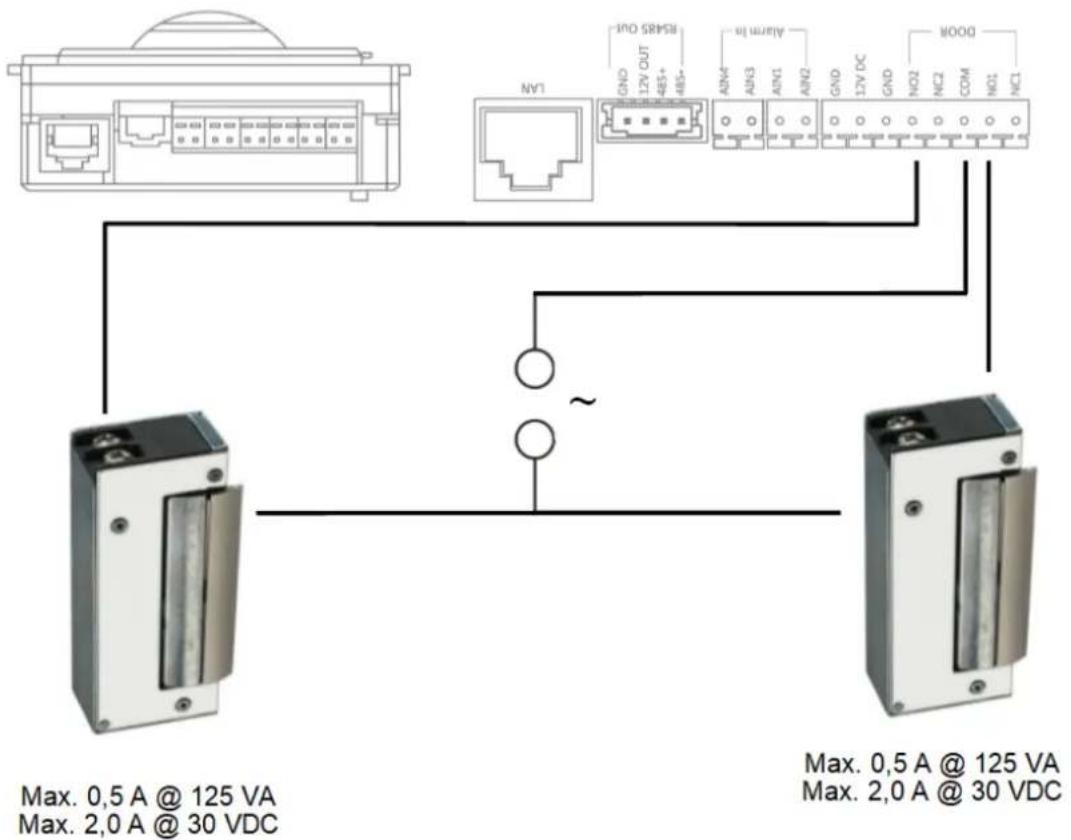
9.16 Relay connection
The door video module relay (TVHS20000(S) / TVHS20010(S)), security module TVHS10040 / TVHS20340 and monitors TVHS20200 / 210 / 220 have maximum loads of 2A 30VDC / 0.5A 125AC. An overload will cause the device to malfunction.
Be sure to determine the power consumption of your current door opener / motorised lock. If the permissible current is exceeded, we recommend connecting an external relay.
The door video module has a separate 12V DC voltage output. This allows an external auxiliary relay to be clamped on directly without further power supply.
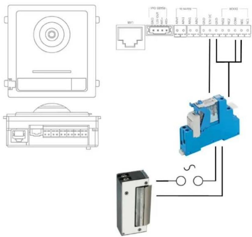
Example: Fully assembled 12V relay PCB with protective diode
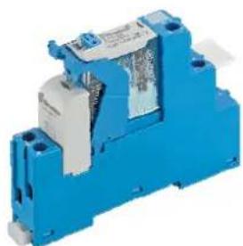
Hat rail relays:
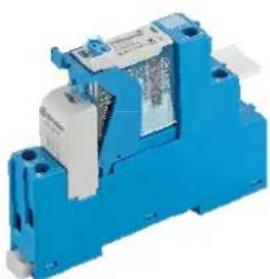
natural_image
Blue industrial component with metallic housing and label (no visible text or symbols)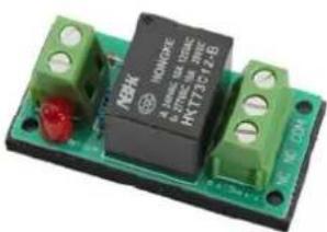
natural_image
Close-up of a green and black electronic component with visible pins and a red indicator (no readable text or symbols)9.17 Instructions for measuring the current door opener
If you would like to control an already existing door opener and do not have any information about the current consumption, determine whether the maximum power consumption will overload the relay before connecting to the door video module relay.
To do this, measure the power consumption using a multimeter. Separate a live cable and switch the ammeter in between (in series).
9.18 Application example "video module in front of every apartment door"
Often there is a desire to also place a video module in front of every apartment door in an apartment building in order to get a 180^ video of the area in front of the apartment door (peepholes are usually very acute-angled in your field of vision).
This can be programmed for up to 16 apartment doors using the "Side entrance" function in the video module.
LAN Version
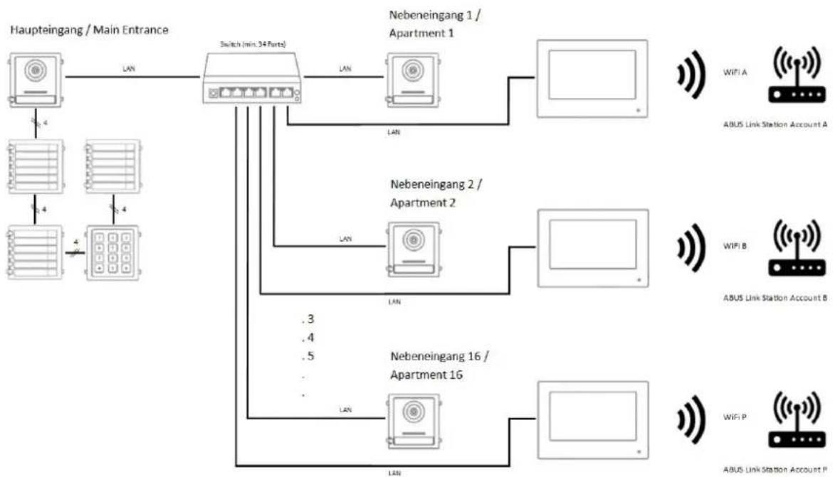
flowchart
graph TD
    A["Haupteingang / Main Entrance"] -->|LAN| B["Switch (min. 34 Parts)"]
    B -->|LAN| C["Nebeneingang 1 / Apartment 1"]
    B -->|LAN| D["Nebeneingang 2 / Apartment 2"]
    B -->|.3| E["Nebeneingang 16 / Apartment 16"]
    B -->|.4| F["Nebeneingang 16 / Apartment 16"]
    B -->|.5| G["Nebeneingang 16 / Apartment 16"]
    B -->|LAN| H["WIFI A"]
    B -->|LAN| I["WIFI B"]
    B -->|LAN| J["WIFI P"]
    B -->|LAN| K["ABUS Link Station Account A"]
    B -->|LAN| L["ABUS Link Station Account B"]
2-wire version
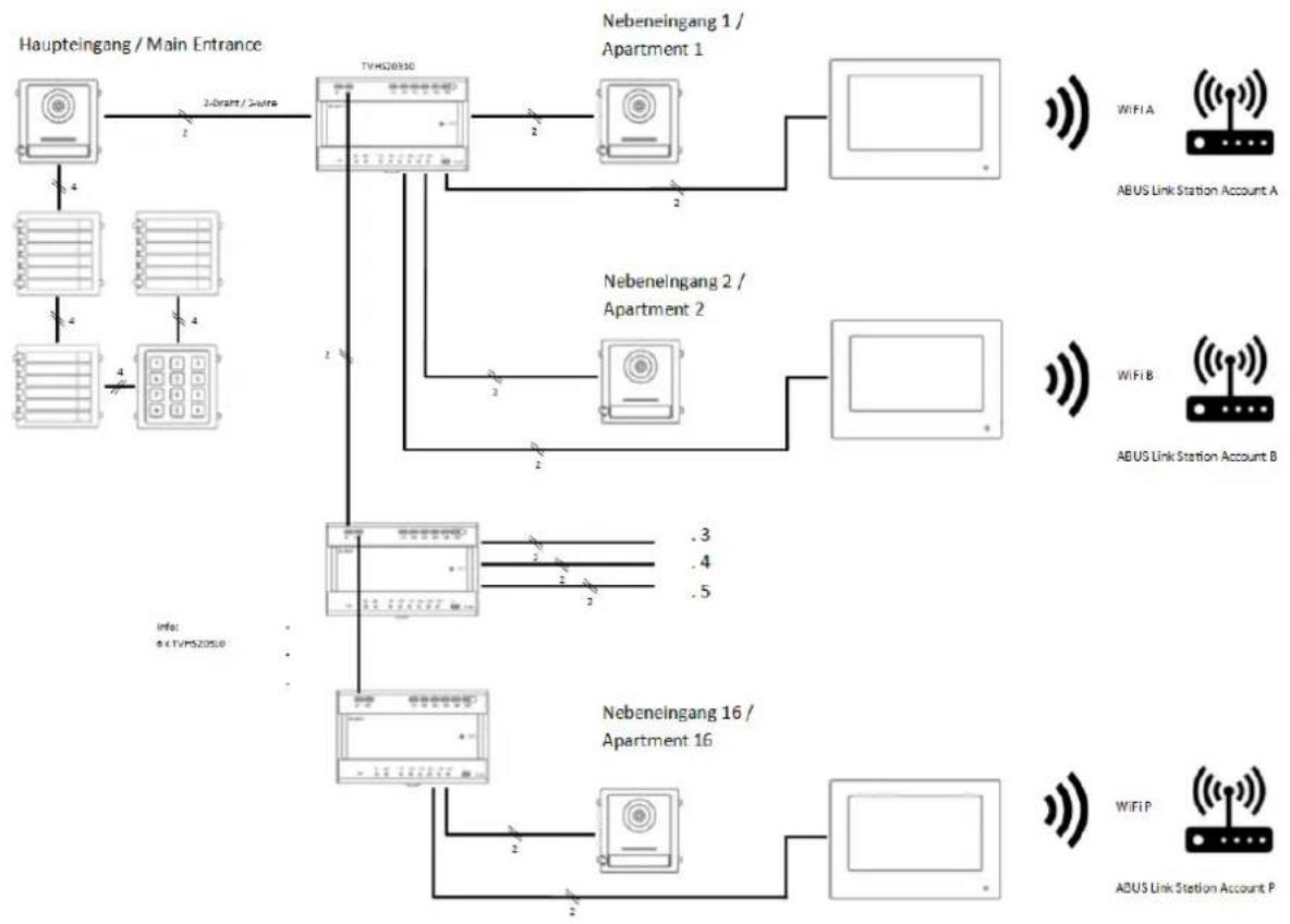
flowchart
graph TD
    A["Haupteingang / Main Entrance"] -->|2-Draft / 2-nurse| B["TVHG20510"]
    B -->|2| C["Nebeneingang 1 / Apartment 1"]
    B -->|2| D["Nebeneingang 2 / Apartment 2"]
    B -->|.3| E["Nebeneingang 16 / Apartment 16"]
    B -->|.4| E
    B -->|.5| E
    F["ABUS Link Station Account A"] --> G["WiFi A"]
    H["ABUS Link Station Account B"] --> I["WiFi B"]
    J["ABUS Link Station Account P"] --> K["WiFi P"]
    L["Info: b < TVHG20510"] --> M["TVHG20510"]
    M --> N["Nebeneingang 16 / Apartment 16"]
    M --> O["Nebeneingang 16 / Apartment 2"]
    M --> P["Nebeneingang 16 / Apartment 3"]
    M --> Q["Nebeneingang 16 / Apartment 4"]
    M --> R["Nebeneingang 16 / Apartment 5"]
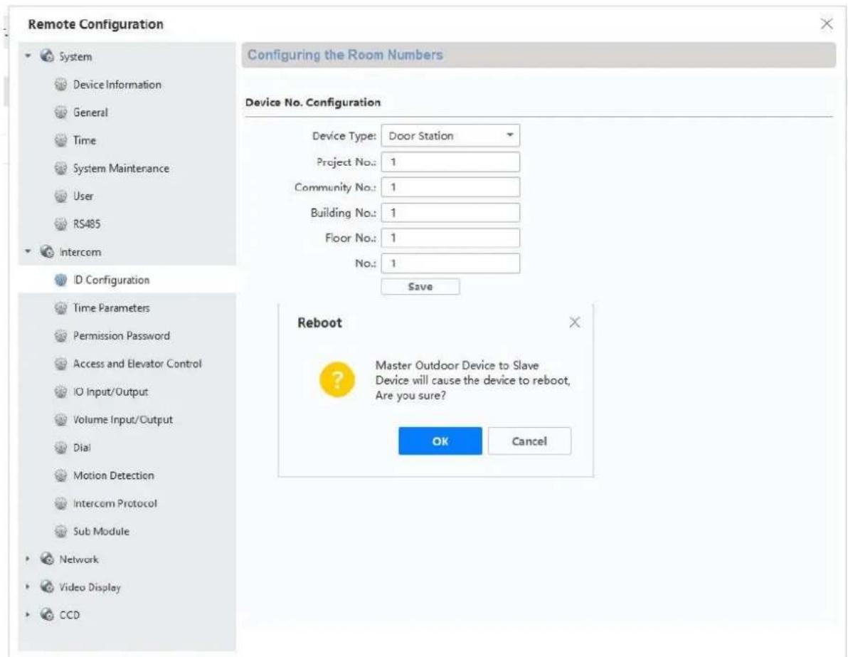
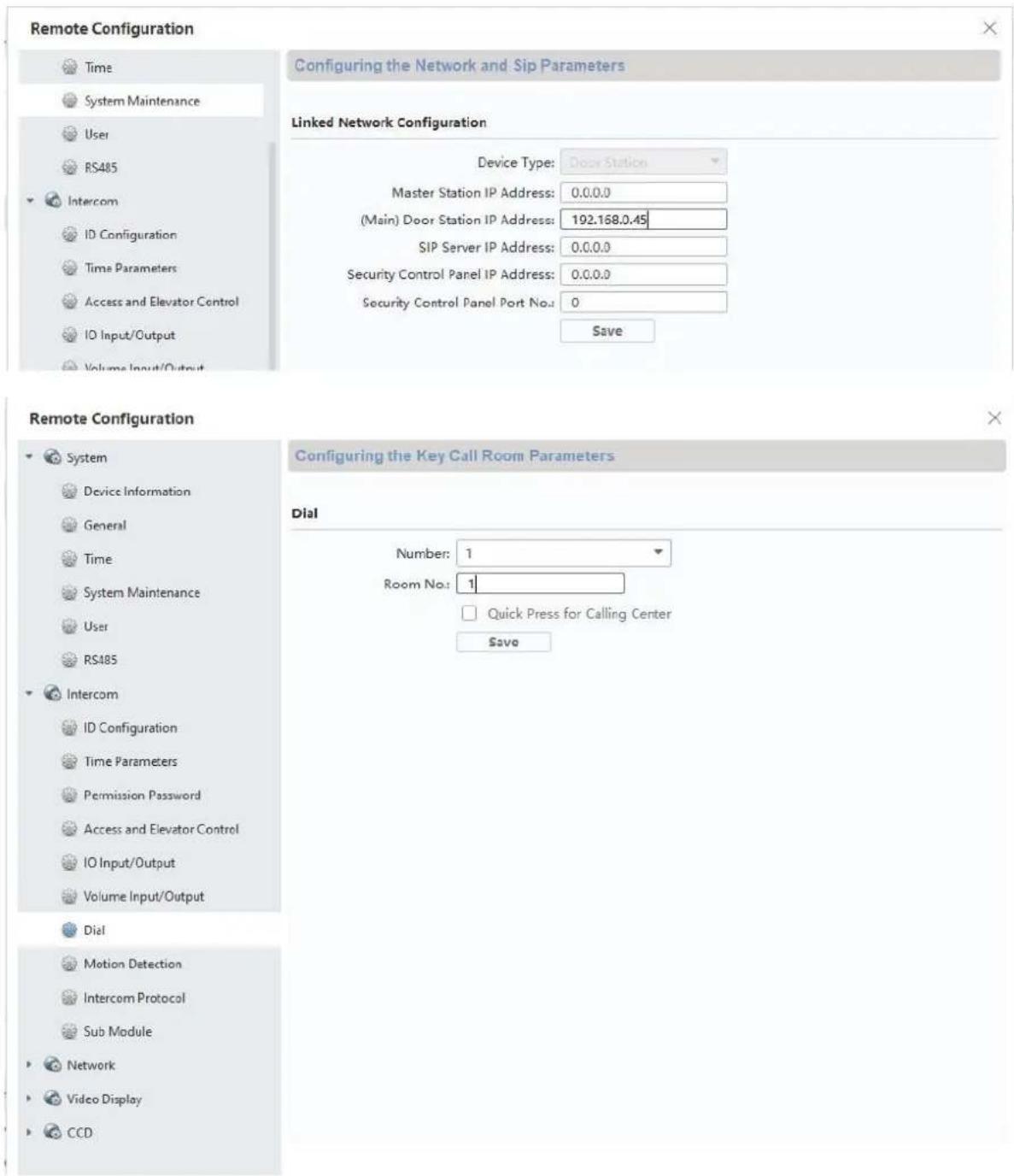
9.19 Application example "Individual WiFi access"
In an apartment building, there is often no central Internet connection for all residential units. Each residential unit may have its own internet connection.
A connection to the customer-specific internet connection can be established via the WiFi function of the main monitor.
This means that there is also access to the ABUS Link Station function with push notification when the doorbell rings individually for each residential unit.
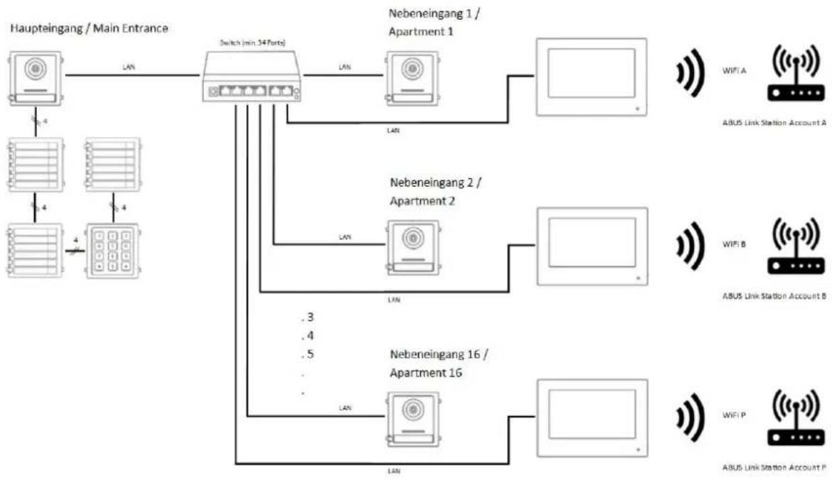
flowchart
graph TD
    A["Haupteingang / Main Entrance"] -->|LAN| B["Switch (min 34 Ports)"]
    B -->|LAN| C["Nebeneingang 1 / Apartment 1"]
    B -->|LAN| D["Nebeneingang 2 / Apartment 2"]
    B -->|LAN| E["Nebeneingang 16 / Apartment 16"]
    C --> F["APPROCTOR"]
    D --> G["APPROCTOR"]
    E --> H["APPROCTOR"]
    F --> I["WIFI A"]
    F --> J["ABUS Link Station Account A"]
    G --> K["WIFI B"]
    G --> L["ABUS Link Station Account B"]
    H --> M["WIFI P"]
    H --> N["ABUS Link Station Account P"]
    B -->|LAN| O[".3, .4, .5, ."]
    B -->|LAN| P[".3, .4, .5, ."]
A document with further information on wiring the 2-wire door intercom system can be found at www.abus.com, e.g. on the TVHS20010 product:
https://www.abus.com/var/ImagesPIM/d110001/medias/docus/25/Moduvis Verkabelung Wiring 2wire_V1.1.pdf
MODUVIS
Interphone
TVHS20XXX(S)
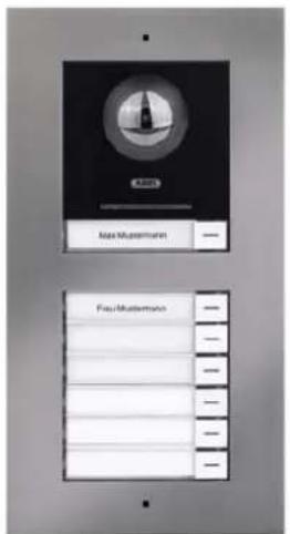
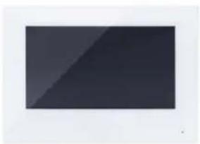
natural_image
Solid dark rectangular shape with no visible text, symbols, or features.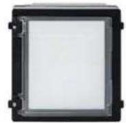
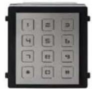


natural_image
Blue square icon with a white telephone handset symbol (no text or numbers)
natural_image
Blue square icon with a white envelope symbol (no text or numbers)
natural_image
Blue square icon with a white eye symbol and corner brackets (no text or symbols)
natural_image
Blue square icon with a white light bulb symbol (no text or numbers)| Journal des images |  | ||||
| 14-03 | |||||
| ABUSSecurity Tech Germany | ABUSSecurity Tech Germany |  | |||
| ABUSSecurity Tech Germany | ABUSSecurity Tech Germany |  | |||
| ABUSSecurity Tech Germany | ABUSSecurity Tech Germany | ||||
natural_image
Pure diagram of six rectangular panels arranged in a grid, no text or symbols presentRemote Configuration
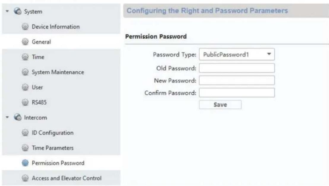
Jusqu'au firmware V2.0.8 / V2.1.2 build 200410:
Remote Configuration


System

Device Information

General

Time

System Maintenance

User

RS485

Intercom

ID Configuration

Time Parameters

Permission Password

Access and Elevator Control

10 Input/Output

Volume Input/Output

Dial

Motion Detection

Intercom Protocol

Sub Module


Network
Configuring Sub Module Information
Module Add... Module Type
Module Status
Module Version
Settings
1
Nametag Module
Online
V1.0.0 ...d190522

2
Keypad Module
Online
V1.0.0...d191009


Remote Configuration

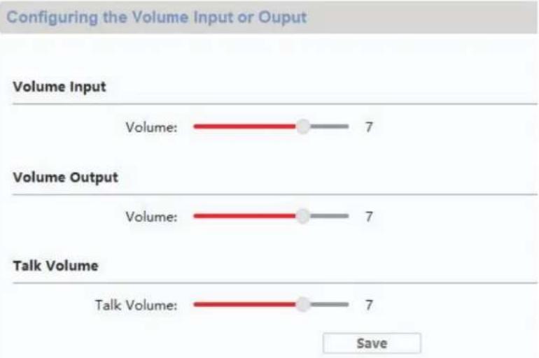
bar
| Category | Value | | -------------- | ----- | | Volume Input | 7 | | Volume Output | 7 | | Talk Volume | 7 |natural_image
Line drawing of a rectangular electronic device with concentric circles and a horizontal bar (no text or symbols)
natural_image
Technical line drawing of a device rear panel with internal connectors and a dome-shaped top (no text or symbols)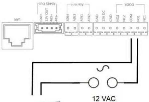
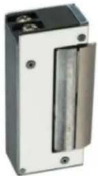
natural_image
Exterior view of a black and white industrial electrical enclosure with a vertical glass door (no visible text or symbols)Max. 0,5 A @ 125 VA
Max. 2,0 A @ 30 VDC

natural_image
Technical line drawing of a device rear panel with internal ports and connectors (no text or symbols)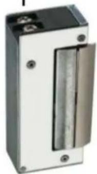
natural_image
Exterior view of a rectangular electronic device with a central vertical glass and two mounting holes (no visible text or symbols)Max. 0,5 A @ 125 VA
Max. 2,0 A @ 30 VDC
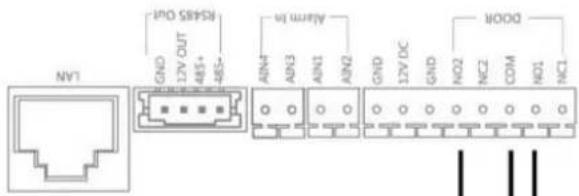

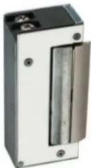
natural_image
Exterior view of a rectangular electronic device with a vertical glass panel and mounting holes (no visible text or symbols)Max. 0,5 A @ 125 VA
Max. 2,0 A @ 30 VDC
Incoming Call Linkage

Relay
Local Network Configuration

Linked Network Configuration

Advanced Settings

ABUS Link Station
Max. 2A @ 30 VDC
Max. 0.5A @ 125 VAC
9.16 Circuit relais
natural_image
Technical line drawing of a device front panel and internal connector housing (no text or symbols)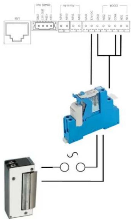
natural_image
Blue and white industrial component with no visible text or symbols
natural_image
Close-up of a green and black electronic component with red indicator lights (no visible text or symbols)Remote Configuration
Time
System Maintenance
User
RS485
Intercom
ID Configuration
Time Parameters
Access and Elevator Control
ID Input/Output
Volume Input/Output
Configuring the Network and Sip Parameters
Linked Network Configuration
Device Type:
Dress Station
0.0.0.0
(Main) Door Station IP Address:
192.168.0.45
SIP Server IP Address:
0.0.0.0
Security Control Panel IP Address:
0.0.0.0
Security Control Panel Port No.:
0
Save
Remote Configuration
System
Device Information
General
Time
System Maintenance
User
RS485
Intercom
ID Configuration
Time Parameters
Permission Password
Access and Elevator Control
IO Input/Output
Volume Input/Output
Dial
Motion Detection
Intercom Protocol
Sub Module
Network
Video Display
CCD
Configuring the Key Call Room Parameters
Dial
Number:
1
▼
Room No.:
1
m = 311
m = 311
Quick Press for Calling Center
Save
natural_image
Solid dark rectangular shape with no visible text, symbols, or features.
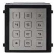

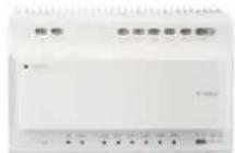

Firmware-release-opmerking
| < | Opnamelogboeken |  | |||
| 14-03 | |||||
| ABUSSecurity Tech Germany | ABUSSecurity Tech Germany |  | |||
| ABUSSecurity Tech Germany | ABUSSecurity Tech Germany |  | |||
| ABUSSecurity Tech Germany | ABUSSecurity Tech Germany | ||||
5.2.1 Menupunt: Oproepinstellingen
Firmware-release-opmerking
Functie: automatisch beantwoorden, direct automatisch beantwoorden Videomodule (THVS20000 / TVHS20010): V2.2.3_build_201029 Monitor (TVHS20200 / TVHS20210): V2.1.2_build_201029
natural_image
Simple line drawing of six rectangular frames arranged in a scattered pattern (no text or symbols)Tot firmware V2.0.8 / V2.1.2 build 200410:
Remote Configuration
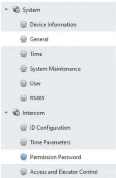

5.2.11 Systeemtaal
Tot firmware V2.0.8 / V2.1.2 build 200410:
Remote Configuration


System

Device Information

General

Time

System Maintenance

User

RS485

Intercom

ID Configuration

Time Parameters

Permission Password

Access and Elevator Control

10 Input/Output

Volume Input/Output

Dial

Motion Detection

Intercom Protocol

Sub Module


Network
Configuring Sub Module Information
| Module Add... Module Type | Module Status | Module Version | Settings | |
| 1 | Nametag Module | Online | V1.0.0 ...d190522 | |
| 2 | Keypad Module | Online | V1.0.0 ...d191009 | |
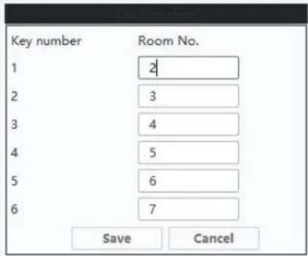
Remote Configuration
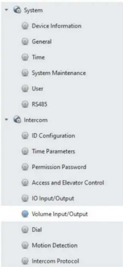

bar
| Category | Value | | -------------- | ----- | | Volume Input | 7 | | Volume Output | 7 | | Talk Volume | 7 |natural_image
Line drawing of a rectangular electronic device with concentric circles and a horizontal bar (no text or symbols)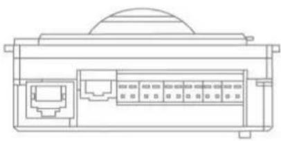
natural_image
Technical line drawing of a device rear panel with internal ports and a dome-shaped top (no text or symbols)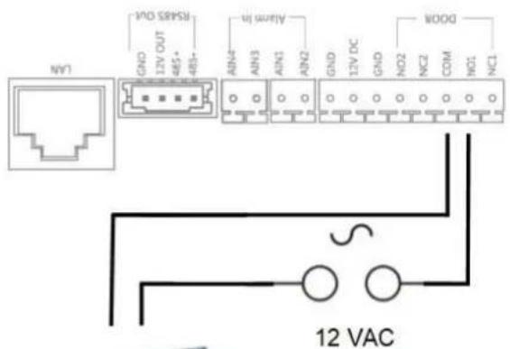

natural_image
Exterior view of a rectangular electronic device with a vertical metallic component and mounting holes (no visible text or symbols)Max. 0,5 A @ 125 VA
Max. 2,0 A @ 30 VDC
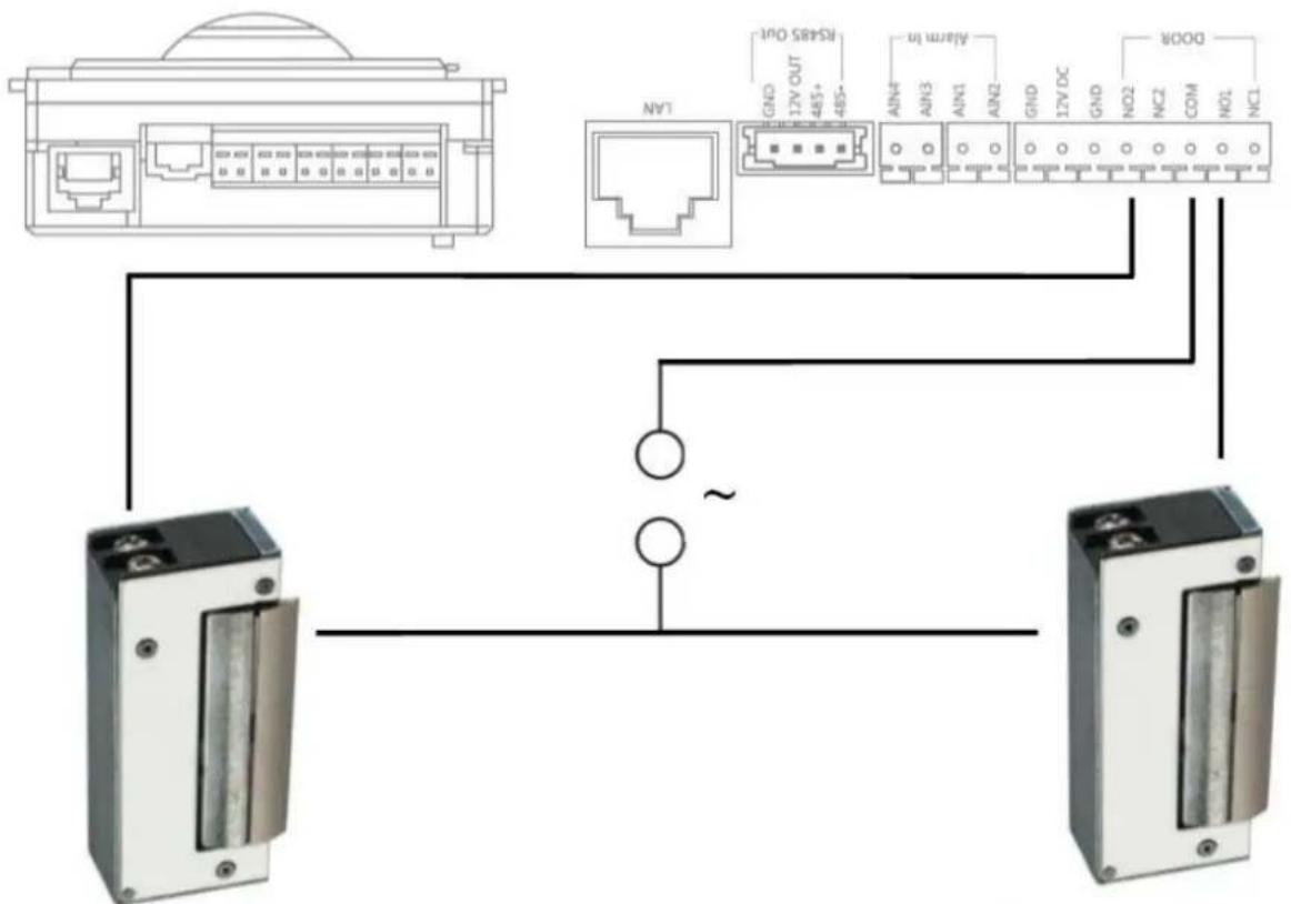
flowchart
graph TD
    A["Router 1"] --> B["IAN"]
    B --> C["Terminal Block"]
    D["Terminal Block"] --> E["Terminal Block"]
    F["RSARS OUT"] --> G["Terminal Block"]
    H["Alarm In"] --> I["Terminal Block"]
    J["DOOR"] --> K["Terminal Block"]
    style A fill:#f9f,stroke:#333
    style D fill:#f9f,stroke:#333
    style F fill:#f9f,stroke:#333
    style H fill:#f9f,stroke:#333
    style J fill:#f9f,stroke:#333
    style B fill:#ccf,stroke:#333
    style E fill:#ccf,stroke:#333
    style K fill:#ccf,stroke:#333
Max. 0,5 A @ 125 VA
Max. 2,0 A @ 30 VDC
Max. 0,5 A @ 125 VA
Max. 2,0 A @ 30 VDC
Remote Configuration

| Ring Configuration | |||||
| Index | Name | Size | Type | Add | Delete |
| 1 | Sprach...1_sd_2 | 185466 | wav | + | × |
| 2 | + | × | |||
| 3 | + | × | |||
| 4 | + | × | |||
9.10 ABUS CMS: firmware Moduvis-componenten update
Remote Configuration
Incoming Call Linkage

Relay

Network

Local Network Configuration

Linked Network Configuration

Advanced Settings

ABUS Link Station
Max. 2A @ 30 VDC
Max. 0.5A @ 125 VAC
9.16 Relaiscircuit
natural_image
Blue industrial component with metallic housing and internal components (no visible text or symbols)
natural_image
Close-up of a green and black electronic component with red indicator lights (no visible text or symbols)Remote Configuration
Time
System Maintenance
User
RS485
Intercom
ID Configuration
Time Parameters
Access and Elevator Control
ID Input/Output
Volume Input/Output
Configuring the Network and Sip Parameters
Linked Network Configuration
Device Type:
Dress Station
Master Station IP Address: (Main) Door Station IP Address: SIP Server IP Address: Security Control Panel IP Address: Security Control Panel Port No.:
0.0.0.0
192.168.0.45
0.0.0.0
0.0.0.0
0
Save
Remote Configuration
System
Device Information
General
Time
System Maintenance
User
RS485
Intercom
ID Configuration
Time Parameters
Permission Password
Access and Elevator Control
IO Input/Output
Volume Input/Output
Dial
Motion Detection
Intercom Protocol
Sub Module
Network
Video Display
CCD
Configuring the Key Call Room Parameters
Dial
Number:
1
▼
Room No.:
1
m = 311
m = 311
Quick Press for Calling Center
Save
natural_image
Solid dark rectangular shape with no visible text, symbols, or features.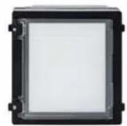


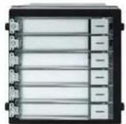
9.8 T ILSLUTNING AF ELEKTRISK D∅RÅBNER TIL VIDEOMODULET (INKL. "HAVELÅGE") ...... 350
9.9 T ILPASNING AF EGNE RINGETONER PÅ D∅RSTATIONENS MONITOR.... 352
9.10 ABUS CMS: UDF∅R FIRMWAREOPDATERING AF MODUVIS-KOMPONENTERNE.... 353
9.11 ABUS CMS: UDVIDEDE INDSTILLINGSMULIGHEDER.... 355
9.12 F UNKTIONER MODUVIS OG ABUS LINK STATION APPEN.... 359
9.13 K OMPATIBILITET MED ABUS PRODUKTER 359
9.14 I NTEGRERING AF VIDEO-D∅RMODULET I ABUS NVR 359
9.15 "N ∅D-D∅RÅBNER"-TAST PÅ D∅R-VIDEOMODULET 360
9.16 R ELÆTILSLUTNING 362
9.17 V EJLEDNING TIL MÅLING AF DEN EKSISTERENDE D∅RÅBNER 363
9.18 A NVENDELSESEKSEMPEL "VIDEOMODUL FORAN HVER LEJLIGHEDSD∅R"...... 363
9.19 A PPLIKATIONSEKSEMPEL "INDIVIDUEL WIFI-ADGANG" 366
10. LEDNINGSF∅RING (2-LEDER) 367
1. Korrekt anvendelse
natural_image
Blue square icon with a white telephone handset symbol (no text or numbers)
natural_image
Blue square icon with a white envelope symbol (no text or numbers)
natural_image
Blue square icon with a white eye symbol and corner brackets (no text or symbols)
natural_image
Blue square icon with a white lightning bolt symbol (no text or numbers)
natural_image
Blue square icon with a white eye symbol and corner brackets (no text or symbols)
| Optagelsesprotokol | | ||||
| 14-03 | |||||
| ABUSSecurity Tech Germany | ABUSSecurity Tech Germany |  | |||
| ABUSSecurity Tech Germany | ABUSSecurity Tech Germany |  | |||
| ABUSSecurity Tech Germany | ABUSSecurity Tech Germany | ||||
natural_image
Pure diagram of six rectangular panels arranged in a grid, no text or symbols presentFra firmware V2.2.3 / V2.1.2 build 201029:
"#" Lejlighedsnummer 6-cifret PIN "#". Eksempel: # 1123456 #
Remote Configuration

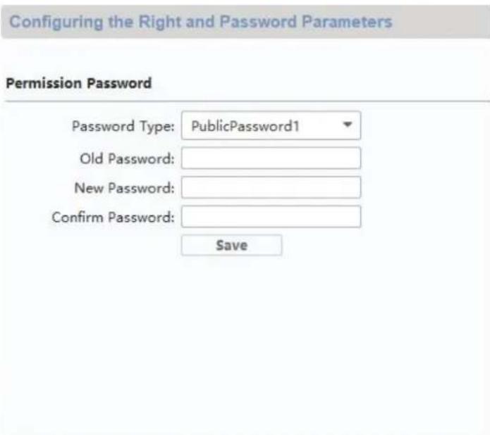
5.2.11 Systemsprog
Op til firmware V2.0.8 / V2.1.2 build 200410:
Fra firmware V2.2.3 / V2.1.2 build 201029:
Remote Configuration


System

Device Information

General

Time

System Maintenance

User

RS485

Intercom

ID Configuration

Time Parameters

Permission Password

Access and Elevator Control

IO Input/Output

Volume Input/Output

Dial

Motion Detection

Intercom Protocol

Sub Module


Network
Configuring Sub Module Information
Module Add... Module Type
Module Status
Module Version
Settings
1
Nametag Module
Online
V1.0.0 ...d190522

2
Keypad Module
Online
V1.0.0...d191009


Remote Configuration

Configuring the Volume Input or Output
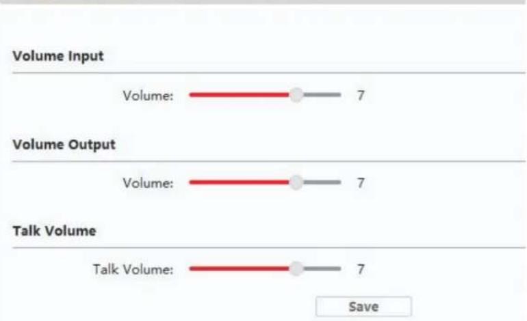
bar
| Category | Value | | -------------- | ----- | | Volume Input | 7 | | Volume Output | 7 | | Talk Volume | 7 |natural_image
Simple line drawing of a rectangular device with a circular top and horizontal base (no text or symbols)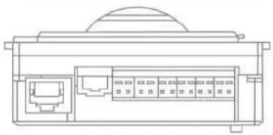
natural_image
Technical line drawing of a device rear panel with internal ports and a dome-shaped top (no text or symbols)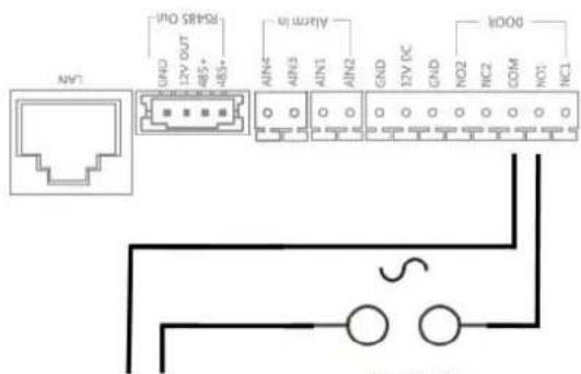
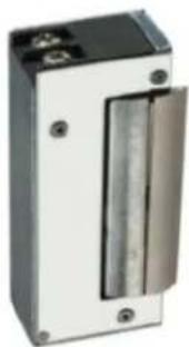
natural_image
Exterior view of a rectangular electronic device with a vertical metallic component and mounting holes (no visible text or symbols)Max. 0,5 A @ 125 VA
Max. 2,0 A @ 30 VDC
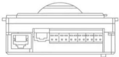
natural_image
Technical line drawing of a mechanical or electronic component with internal ports and a dome-shaped top (no text or symbols)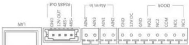
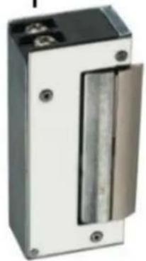
natural_image
Exterior view of a rectangular electronic device with a metallic panel and two terminals (no visible text or symbols)Max. 0,5 A @ 125 VA
Max. 2,0 A @ 30 VDC
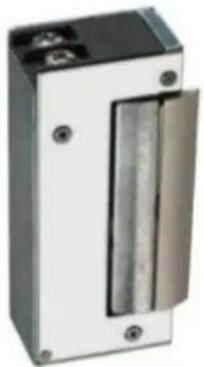
natural_image
Exterior view of a rectangular electronic device with a metallic panel and mounting holes (no visible text or symbols)Max. 0,5 A @ 125 VA
Max. 2,0 A @ 30 VDC
Remote Configuration
System
Device Information
General
Time
System Maintenance
User
RS485
Intercom
Network
Video Display
CCD
Displaying the Device Information
Basic Information
Device Type: TVHS20000
Device Serial No.: TVHS200000120200110RRP11705670
Version Information
Version: V2.2.3 build 201029
Hardware Version: 0x0
Remote Configuration
| System |
| Device Information |
| General |
| Time |
| System Maintenance |
| User |
| RS485 |
| Intercom |
| ID Configuration |
| Time Parameters |
| Permission Password |
| Access and Elevator Control |
| IO Input/Output |
| Volume Input/Output |
| Dial |
| Motion Detection |
| Intercom Protocol |
| Sub Module |
| Network |
| Local Network Configuration |
| Linked Network Configuration |
| FTP Settings |
| Advanced Settings |
| Video Display |
| Video Parameters |
| Video Display |
| Video & Audio |
| CCD |
| Back Light Compensation |
Max. 2A @ 30 VDC
Max. 0.5A @ 125 VAC
9.16 Relætilslutning
natural_image
Blue industrial component with metallic housing and mounting holes (no visible text or symbols)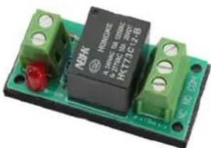
natural_image
Close-up of a green electronic component with black and red pins, no visible text or symbols on the main body.Remote Configuration
Time
System Maintenance
User
RS485
Intercom
ID Configuration
Time Parameters
Access and Elevator Control
ID Input/Output
Volume Input/Output
Configuring the Network and Sip Parameters
Linked Network Configuration
Device Type:
Dress Station
0.0.0.0
(Main) Door Station IP Address:
192.168.0.45
SIP Server IP Address:
0.0.0.0
Security Control Panel IP Address:
0.0.0.0
Security Control Panel Port No.:
0
Save
Remote Configuration
System
Device Information
General
Time
System Maintenance
User
RS485
Intercom
ID Configuration
Time Parameters
Permission Password
Access and Elevator Control
IO Input/Output
Volume Input/Output
Dial
Motion Detection
Intercom Protocol
Sub Module
Network
Video Display
CCD
Configuring the Key Call Room Parameters
Dial
Number:
[Non-Text]
-
Room No.:
1
1 + u7 = 7019
The Ground Truth image displays a single, solid horizontal line. According to Rule 2 (UNDERSCORE & LINE RULES), this is a stylistic or background line, not a placeholder underscore. Therefore, the OCR result must ignore it and output nothing or only meaningful text. The provided OCR content is "____", which consists of four underscores. This is an incorrect interpretation of the line as a placeholder, violating the rule that stylistic lines must be ignored. The OCR has hallucinated underscores where none should exist based on the GT's visual context. Hence, the OCR result is inconsistent with the Ground Truth.
Quick Press for Calling Center
Save
9.19 Applikationseksempel "Individuel WiFi-adgang"

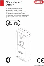

- Bedienungsanleitung
- Remote Configuration
- User manual
- EN Introduction
- TVHS20000 / TVHS20000S
- TVHS20010 / TVHS20010(S)
- TVHS20020 / TVHS20020(S)
- TVHS20030 / TVHS20030S
- TVHS20040
- TVHS20200
- TVHS20210
- TVHS20220
- TVHS10040 / TVHS20340
- Disclaimer
- Important safety information
- Dear customer,
- Contents
- Intended use
- Explanation of symbols
- System overview
- 2-wire variant
- Components
- Recommended cable types
- IP network variant
- Components
- Installation components
- Start-up
- Wiring
- Installation height
- Activation options / initial password assignment
- Activation via door station monitor
- Firmware version note
- Indoor station:
- Interior extension:
- 5) "Assistant-connected devices"
- Activation via IP network
- Password reset for monitor/video door module
- Monitor operation (2-wire & IP)
- Live image
- Main page overview
- Call
- Contacts
- Call log
- Visitor notification (answering machine)
- Recording log
- Menu item: Call settings
- Firmware release note
- Wi-Fi settings
- Floor buttons
- Other settings
- Configuration – local information
- ABUS Link Station service settings:
- Procedure:
- Configuration – network settings
- Configuration – device management
- Device Management
- Attention:
- Configuration – default settings
- Default settings:
- Relay configuration
- Connecting an existing doorbell" in the section Installation and operating information.
- microSD card
- Lock screen
- Device information
- Time setting
- Restart device
- Password settings (PIN CODE)
- System language
- Brightness setting
- Floor button
- Open Source Licence information
- Maintenance and cleaning
- Function test
- Please note:
- Cleaning
- Disposal
- Open Source Licence information
- Installation and operating information
- Using the security module (TVHS10040)
- Setting up back doors
- Setting up extended call buttons (TVHS20020) for multi-family homes
- Configuring Sub Module Information
- Adjusting the volume on the door video module (TVHS20000(S), TVHS20010(S))
- Connecting an existing doorbell
- Connecting existing door openers to the door station monitor
- Connecting floor call buttons to the main monitor
- Connecting electrical door openers to the video module (including "garden gate")
- Plays your own ring tones in the door station monitor
- System
- intercom
- Network
- ABUS CMS: Perform firmware update for Moduvis components
- ABUS CMS: Advanced setting options
- MODUVIS and ABUS Link Station app range of functions
- Compatibility with ABUS products
- Connecting the video door module to ABUS NVR
- "Emergency door opener" button on door video module
- Relay connection
- Instructions for measuring the current door opener
- Application example "video module in front of every apartment door"
- LAN Version
- Application example "Individual WiFi access"
- MODUVIS
- Interphone
- TVHS20XXX(S)
- Circuit relais
- Configuring the Network and Sip Parameters
- Linked Network Configuration
- Configuring the Key Call Room Parameters
- Dial
- Firmware-release-opmerking
- Menupunt: Oproepinstellingen
- Systeemtaal
- ABUS CMS: firmware Moduvis-componenten update
- Relaiscircuit
- LEDNINGSF∅RING (2-LEDER) 367
- Korrekt anvendelse
- Systemsprog
- Op til firmware V2.0.8 / V2.1.2 build 200410:
- Fra firmware V2.2.3 / V2.1.2 build 201029:
- Basic Information
- Version Information
- Relætilslutning
- Applikationseksempel "Individuel WiFi-adgang"
Brand : ABUS
Model : TVHS20040
Category : Security and Access Control System