
Linear 5 MK II 118 Sub A - Subwoofer HK AUDIO - Free user manual and instructions
Find the device manual for free Linear 5 MK II 118 Sub A HK AUDIO in PDF.

| Product type | Active subwoofer |
| Brand | HK Audio |
| Model | Linear 5 MK II 118 Sub A |
| Category | Subwoofer |
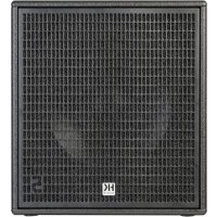
| Dimensions (W x H x D) | 61 x 61 x 79 cm |
| Weight | 53.4 kg |
| Housing material | Birch plywood, black acrylic lacquer |
| Grille | 2 mm metal grille with black acoustic foam |
| Speaker | 1 x 18" with 4" voice coil |
| Max SPL (peak, 10% THD) | 131 dB half-space |
| Frequency response +/-3 dB | 36 Hz - Crossover |
| Frequency response -10 dB | 33 Hz - Crossover |
| Output stage power (RMS / peak) | 1500 / 3000 W |
| Output stage type | Class D |
| Analog inputs | 2 balanced combo XLR/jack inputs (L and R) |
| Analog outputs (Thru) | 2 balanced XLR |
| DSP Out output | 1 balanced XLR |
| Network connection | etherCON RJ45, 1 input, 1 loop-through |
| Presets | Front, Cardioid 1:1 vertical, Cardioid 2:1 vertical, Remote |
| Control software | DSP CONTROL (Windows, macOS) |
| Power supply | 100-240 V~ 50-60 Hz |
| Rated power consumption | 2.5 A @ 1/8 output power |
| Power connector | PowerCON NAC3 input, powerCON NAC3 loop-through |
| Pole mount | 1 x M20 |
| Handles | 4 x MultiGrip |
| Auto Sleep function | Yes (switchable, standby after 4.5 h without signal) |
| Included accessories | PowerCON power cable, quick start guide, RCS cover |
Frequently Asked Questions - Linear 5 MK II 118 Sub A HK AUDIO
User questions about Linear 5 MK II 118 Sub A HK AUDIO
0 question about this device. Answer the ones you know or ask your own.
Ask a new question about this device
Download the instructions for your Subwoofer in PDF format for free! Find your manual Linear 5 MK II 118 Sub A - HK AUDIO and take your electronic device back in hand. On this page are published all the documents necessary for the use of your device. Linear 5 MK II 118 Sub A by HK AUDIO.
USER MANUAL Linear 5 MK II 118 Sub A HK AUDIO
natural_image
Technical line drawing of a mechanical device with internal compartments and mounting holes (no text or symbols)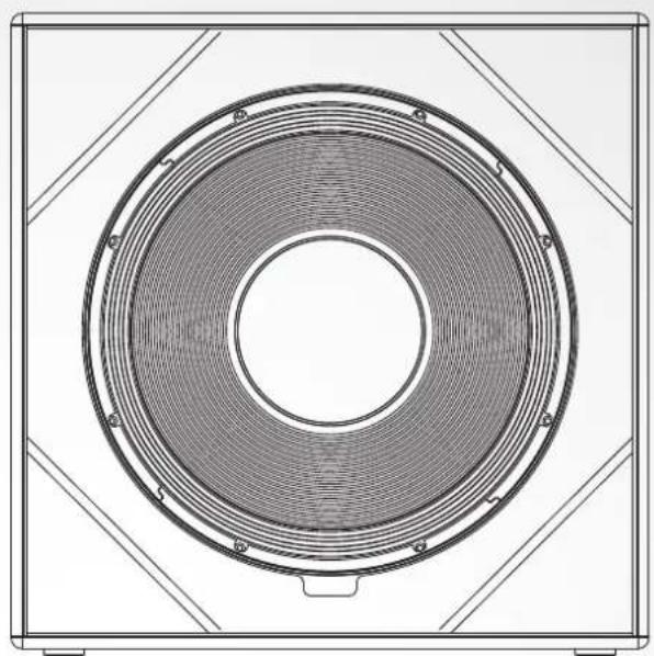
natural_image
Technical line drawing of a circular fan or speaker component with concentric rings and mounting brackets (no text or symbols)LINEAR 5 MK II
Important Safety Instructions! Read before connecting!
This product has been built by the manufacturer in accordance with IEC 62368-1 and left the factory in safe working order. To maintain this condition and ensure non-risk operation, the user must follow the advice and warning comments found in the operating instructions. If this product shall be used in vehicles, ships or aircraft or at altitudes exceeding 2000 m above sea level, take care of the relevant safety regulations which may exceed the IEC 62368-1 requirements.
WARNING: To prevent the risk of fi re and shock hazard, do not expose this appliance to moisture or rain. Do not open case – no user serviceable parts inside. Refer service to qualified service personnel.

This symbol, wherever it appears, alerts you to the presence of rated dangerous voltage inside the enclosure – voltage that may be not to constitute a risk of shock.

This symbol, wherever it appears, alerts you to the presence of a accessible hazardous voltage. External wiring connected to any marked with this symbol must be a "ready made cable" complying manufacturers recommendations, or must be a wiring installed by persons only.

This symbol, wherever it appears, alerts you to important and maintenance instructions in the accompanying literature. manual.

This symbol, wherever it appears, tells you: Take care! Hot surface! at burns you must not touch.

All electrical and electronic products including batteries should be of separately from the municipal waste stream via designated facilities appointed by the government or the local authorities.

Read these instructions. Keep these instructions. Follow all warnings ructions marked on the product and in this manual.
- Do not use this product near water. Do not place the product near water, baths, wash basins, kitchen sinks, wet areas, swimming pools or damp rooms.
- Do not place objects containing liquid on the product – vases, glasses, bottles etc.
- Clean only with dry cloth.
- Do not remove any covers or sections of the housing.
- The set operating voltage of the product must match the local mains supply voltage. If you are not sure of the type of power available consult your dealer or local power company.
- Before connecting the device, please ensure that the mains supply you are using is equipped with adequate protection against short circuiting and grounding faults when the device is plugged in.
- To reduce the risk of electrical shock, the grounding of this product must be maintained. Use only the power supply cord provided with this product, and maintain the function of the center (grounding) pin of the mains connection at any time. Make sure the mains outlet used provides a proper protective ground connection.
- Do not defeat the safety purpose of the polarized or grounding-type plug. A polarized plug has two blades with one wider than the other. A grounding type plug has two blades and a third grounding prong. The wide blade or the third prong are provided for your safety. If the provided plug does not fit into your outlet, consult an electrician for replacement of the obsolete outlet.
- Protect the power cord from being walked on or pinched particularly at plugs, convenience receptacles, and the point where they exit from the device! Power supply cords should always be handled carefully. Periodically check cords for cuts or sign of stress, especially at the plug and the point where the cord exits the device.
- Never use a damaged power cord.
- Unplug this product during lightning storms or when unused for long periods of time.
- This product can be fully disconnected from mains only by pulling the mains plug at the unit or the wall socket. The product must be placed in such a way at any time, that disconnecting from mains is easily possible.
- Fuses are to be replaced exclusively by qualified personnel, and then only with fuses of the proper type and rating.
- Refer all servicing to qualified service personnel. Servicing is required when the unit has been damaged in any way, such as:
- When the power cord or plug is damaged or frayed.
- If liquid has been spilled or objects have fallen into the product.
- If the product has been exposed to rain or moisture. - If the product does not operate normally when the operating instructions are followed. - If the product has been dropped or the cabinet has been damaged. - Do not connect external speakers to this product with an impedance lower than the rated impedance given on the product or in this manual. Use only cables with sufficient cross section according to the local safety regulations.
- Keep away from direct sunlight.
- Do not install near heat sources such as radiators, heat registers, stoves or other devices that produce heat.
- This apparatus is for moderate climates areas use, not suitable for use in tropical climates countries.
- Do not block any ventilation openings. Install in accordance with manufacturer's instructions. This product must not be placed in a built-in installation such as a rack unless proper ventilation is provided.
- Always allow a cold device to warm up to ambient temperature, when being moved into a room. Condensation can form inside it and damage the product, when being used without warming up.
- Do not place naked flame sources, such as lighted candles on the product. - The device must be positioned at least 20 cm/8" away from walls.
- Use only with the cart, stand, tripod, bracket or table specified by the manufacturer or sold with the product. When a cart is used, use caution when moving the cart/product combination to avoid injury from tip-over
- Use only accessories recommended by the manufacturer, this applies for all kind of accessories, for example protective covers, transport bags, stands, wall or ceiling mounting equipment. In case of attaching any kind of accessories to the product, always follow the instructions for use, provided by the manufacturer. Never use fixing points on the product other than specified by the manufacturer.
- This appliance is NOT suitable to be used by any person or persons (including children) with limited physical, sensorical or mental ability, or by persons with insufficient experience and/or knowledge to operate such an appliance. Children under 4 years of age must be kept away from this appliance at all times.
- Never push objects of any kind into this product through cabinet slots as they may touch dangerous voltage points or short out parts that could result in risk of fire or electric shock.
- This product is capable of delivering sound pressure levels in excess of 90 dB, which may cause permanent hearing damage! Exposure to extremely high noise levels may cause a permanent hearing loss. Wear hearing protection if continuously exposed to such high levels.
- The manufacturer only guarantees the safety, reliability and efficiency of this product if:
- Assembly, extension, re-adjustment, modifications or repairs are carried out by the manufacturer or by persons authorized to do so.
- The electrical installation of the relevant area complies with the requirements of IEC (ANSI) specifications.
- The unit is used in accordance with the operating instructions.
- This product is optimized for use with music and speech signals. Using this product with sine wave, square wave or other kind of measuring signals at higher level may lead to severe damage of the product.
General Notes on Safety for Loudspeaker Systems

Mounting systems may only be used for those loudspeaker systems authorized by the manufacturer and only with the mounting accessories specified by the manufacturer in the installation instructions. Read and heed the manufacturer's installation instructions. The indicated load-bearing capacity cannot be guaranteed and the manufacturer will not be liable for damages in the event of improper installation or the use of unauthorized mounting accessories.
The system's load-bearing capacity cannot be guaranteed and the manufacturer will not be liable for damages in the event that loudspeakers, mounting accessories, and connecting and attaching components are modified in any way.
Components affecting safety may only be repaired by the manufacturer or authorized agents, otherwise the operating permit will be voided.

Installation may be performed qualifi ed personnel only, and then only at pick-points with suffi cient load-carrying capacity and in compliance with local building regulations. Use only the mounting hardware specifi ed by the manufacturer in the installation instructions (screws, anchors, etc.). Take all the precautions necessary to ensure bolted connections and other threaded locking devices will not loosen.

Fixed and portable installations (in this case, speakers and mounting accessories) must be secured by two independent safeties to prevent them from falling. Safeties must be able to catch accessories or parts that are loose or may become loose. Ensure compliance with the given national regulations when using connecting, attaching, and rigging devices. Factor potential dynamic forces (jerk) into the equation when determining the proper size and load-bearing capacity of safeties.

Be sure to observe speaker stands' maximum load-bearing capacity, that for reasons of design and construction, most speaker stands are tied to bear centric loads only; that is, the speakers' mass has to be fully centered and balanced. Ensure speaker stands are set up stably securely. Take appropriate added measures to secure speaker stands, simple when:
- the floor or ground surface does not provide a stable, secure base. - they are extended to heights that impede stability.
- high wind pressure may be expected.
- there is the risk that they may be knocked over by people. Special measures may become necessary as precautions against unsafe audience behavior. Do not set up speaker stands in evacuation routes and emergency exits. Ensure corridors are wide enough and put proper barriers and markings in place when setting speaker stands up in passageways. Mounting and dismounting are especially hazardous tasks. Use aids suitable for this purpose. Observe the given national regulations when doing so.


Wear proper protection (in particular, a helmet, s) and use only suitable means of ascent (ladders, installation. Compliance with this requirement is the company performing the installation.

WARNING! After installation, inspect the system comprised of the ring fixtures and loudspeakers to ensure it is properly secured. Operator of loudspeaker systems (fi xed or portable) must regularly or task a third party to regularly inspect all system components in accordance with the given country's regulations and have possible defects and immediately.
We also strongly recommend maintaining a logbook or the like to document all inspections.
Also be sure to provide sufficient safety margins for the rigging points used for fl own systems. Observe the given national regulations when doing so.

Professional loudspeaker systems can produce harmful volume Even prolonged exposure to seemingly harmless levels (starting at 95 dBA SPL) can cause permanent hearing damage! Therefore we mend that everyone who is exposed to high volume levels produced loudspeaker systems wears professional hearing protection (earplugs orifs).
Manufacturer: Stamer Musikanlagen GmbH, Magdeburger Str. 8, 66606 St. Wendel, Germany
natural_image
Technical line drawing of a mechanical enclosure with ventilation ducts and internal components (no text or symbols)
natural_image
Technical line drawing of a speaker grille with concentric rings and mounting brackets (no text or symbols)Welcome to the HK Audio family!
Thank you for choosing a brand-name product made by our company. It was engineered and built with the greatest care so it will serve you well for many tomorrows to come.

Even if you already have extensive experience with sound systems, there will still be some things that are new to you about this product. So be sure to read these operating instructions carefully and keep them for future reference.
Here's wishing you the best sound at every occasion!
Your HK Audio Team

Note: This product's performance may be affected by strong electromagnetic fields or electrostatic discharges. If this occurs, its functionality can be restored by switching it off and on again. If this does not help, you will need to move the device away from the source of interference.
Warranty
Register online with ease at www.hkaudio.com.

http://warranty.hkaudio.com
The warranty registration is only valid if made within 30 days of the date of purchase.
HK Audio
Technical service
Postfach 1509
66595 St. Wendel, Germany
Fax: +49 6851 905 100
1 General Information
Items delivered
When you first unpack your LINEAR 5 MK II speaker cabinet, please check that it comes complete with the Quick Start Guide, a PowerCon mains cable, instructions for safe commissioning and an RCS (Rain Cover Set).
2 Connections and controls
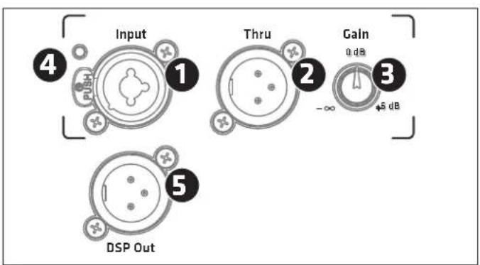
XLR/jack combo socket, balanced input for analogue signals.
• The mid/high model has one input channel.
- The subwoofer has two separate inputs for the left and right signals. The two channels are equal and summed post-preamp, so you can use either one in mono mode.
2
Thru
Use this parallel, balanced XLR output to send the signal routed into the Input through to other components. This output remains active even when the electronic components are deactivated. The subwoofer has two of these ports.
3 Gain
Use this knob to adjust the input gain for the incoming signal.
- For the mid/high model -∞ (Mute) to +6 dB
- This knob adjusts the gain for both of the subwoofer's stereo preamp channels in a range of -6 to +6 dB.
The centre-notched 12 o'clock position is 0 dB in both cases.
Note: The Gain setting does not affect the signal sent to the DSP Out.
4 Input/Limiter LED
This LED lights up green to indicate incoming signals. When it is red, either the limiter is active or the input is clipping. The LED briefly flashes red to tell you the Limiter is responding to signal peaks. If it stays red, turn down the Gain knob.
5 DSP Out
Balanced XLR socket, used to output the analogue input signal (coming from the Input socket). The signal can be processed with the internal DSP using the DSP CONTROL software. This means the DSP Out can serve as a network interface that lets you integrate an added powered speaker that is not originally network-compatible. In the factory default configuration, the unprocessed input signal goes straight to DSP Out, regardless of the selected preset and the Gain knob setting.
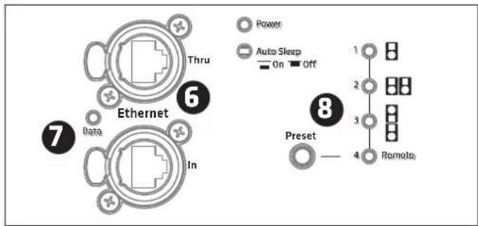
6 Ethernet In /Thru
Use the two etherCON ports to integrate the speaker into a network. They accept RJ45 and etherCON (NE8 MX, NE8 MX6, NE8 MC) plugs. Use the Ethernet Thru port to forward the network signal.
Always use S/STP or S/FTP cables to shield against electromagnetic interference. We recommend CAT6 cables. A separate manual explains the finer points of network integration and remote control functions. You will find it on the LINEAR 5 MK II download page at www.hkaudio.com. For a brief description of the DSP functions, see section 8 Preset.
7 Data
This LED lights up orange when data is being transferred via the network socket.
8 Preset
Use the Preset selection button to call up factory presets or a user preset you can configure via the remote DSP CONTROL software. Tap the select button once to scroll through Presets 1 to 4.
A separate manual explains how to program the four remote user presets. You will find it on the DSP CONTROL software download page at www.hkaudio.com.
Preset overview:
| LINEAR 5 MK II 308 LTA | LINEAR 5 MK II Sub 118 HPA | |
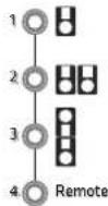 |  | |
| 1 Stand Alone Front | ||
| 2 Cluster (2) Cardioid 1:1 | ||
| 3 Headstack (3) Cardioid 2:1 | ||
| 4 Remote (to access stored settings via the remote HK Audio DSP CONTROL software) | ||
| Front Standard operating mode for a front-firing subwoofer | |
| Cardioid 1:1 For cardioid operation with a front-firing LINEAR 5 MK II Sub 118 HPA | |
| Cardioid 2:1 For cardioid operation with two front-firing LINEAR 5 MK II Sub 118 HPA |
Factory presets 1 to 3 address the speaker only and not the DSP Out.
Note: If you are operating the speaker in a network connected to the remote DSP CONTROL software, you can configure the DSP Out independently even when using factory presets 1 to 3. To learn more about this, consult the separate DSP CONTROL manual. You will find it on the DSP CONTROL software download page at www.hkaudio.com.
The Remote Preset
| Remote | This lets you call up a user preset that you previously stored in the speaker via DSP CONTROL for the speaker as well as for the DSP Out. The speaker does not need to be connected to the remote software to do this. |
The remote preset's default setup is identical to factory preset 1 (Stand Alone and Front).
You can access the following DSP functions via the remote DSP CONTROL software and save your settings in user presets:
Fully parametric 10-band EQ with variable filter characteristics for each frequency band, high-pass and low-pass filters with variable filter characteristics, Limiter, Delay, Polarity, Level, and Mute.
You can configure these parameters separately and independently for the speaker and its DSP Out.
Screenshot of the remote DSP CONTROL software. You can download this software from the DSP CONTROL software download page at www.hkaudio.com. The speaker and DSP Out parameters are identical, but the double DSP power lets you configure each set independently.
9 Power
This rocker switch turns the power on and off. Set it to Power to turn the electronic components on and to Off to disconnect them from the mains power supply. The mains switch has no influence on the PowerCon Link socket (see also 12).
10 Power LED
As soon as the electronic components are supplied with voltage, this LED lights up green.
11 Mains Input
The mains connection is designed as a PowerCon socket. A corresponding mains cable is supplied. Make sure the PowerCon cable clicks into place and locks by pressing and turning it clockwise. To unlock, pull the locking device of the PowerCon connector towards the cable and turn it anticlockwise.
12 Link
This output can be used to supply power to up to three additional LINEAR speaker cabinets with a PowerCon connection. This socket is permanently connected to the mains input and is not affected by the power switch. It carries voltage as soon as the mains input is connected to a live cable. It is therefore important that devices to be connected are switched off before they are connected to this output!
13 Auto Sleep
Use this recessed button to switch energy-saving Auto Sleep mode on and off. Your speaker leaves the factory with the Auto Sleep button pressed to enable this mode. This function puts the electronic components into Auto Sleep when four and a half hours pass without the speaker registering an audio signal, data sent to the network ports, or operation of a button or knob on the electronics. The only way to wake it up is by switching the Power button off and on again or patching an analogue audio signal into the Input.
Heads Up: You cannot wake up the speaker via the network ports.
The only way to disable the Auto Sleep function is to press the recessed switch (not pressed).
3 Alignment
Single
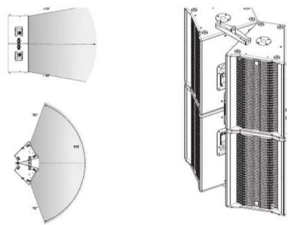
The dispersion angle of the LINEAR 5 MK II 308 LTA is +5°/-25° vertically (fig. 1) and 60° horizontally (fi g. 2). Reflections from walls can be minimised by aligning the speakers horizontally. By turning the speaker, the sound can be focused on the listening area.
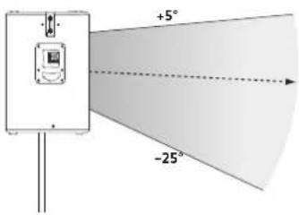
Fig: 1 Vertical dispersion
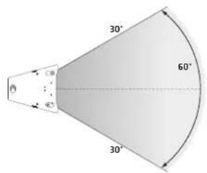
Fig: 2 Horizontal dispersion
When using the LINEAR 5 MK II 308 LTA on speaker stands or mounting poles, it is not necessary to angle the speaker on the vertical axis. The MCT horn gives a vertical dispersion pattern similar to the curving of a properly set up component array. The sound energy is thus concentrated directly on the area to be covered.
If the speaker cabinet is arranged vertically (baffl e 90° to the installation surface):
- Although the speaker fl ange is designed for 0irc , the vertical dispersion angle is +5irc / -25irc .
• The vertical acoustic centre axis is about -3irc . -
Ceiling reflections are massively reduced due to this asymmetrical dispersion.
-
The height of the speaker cabinet therefore defines the range. As a guideline: If the centre of the speaker cabinet is at a height between 2.50 m (Fig. 3) and 2.80 m (Fig. 4), the central axis hits the ears of the listeners after 15.50 m - 21 m for a person measuring 1.70 m tall.
- In rigging operations, horizontal and vertical alignment should preferably be achieved using the optionally available tilt bracket. Rigging the speaker cabinet allows for greater range and sound distribution over a larger area.
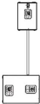
Headstack
Due to the asymmetrical dispersion of the MCT horn, the LINEAR 5 MK II 308 LTA makes it possible to operate two speakers acoustically correctly as a "vertical headstack". In this scenario, the two speakers are coupled and the sound energy is bundled. This results in a vertical dispersion of +10°/-10° and a signifi cant increase in the sound coverage depth. If a greater sound coverage depth is required, the headstack version is recommended. To do this, the second speaker is rotated by 180° with its top plate placed on the top plate of the fi rst speaker (the upper speaker is then "upside down" and the front grilles of both speakers are facing forward) (Fig. 5)
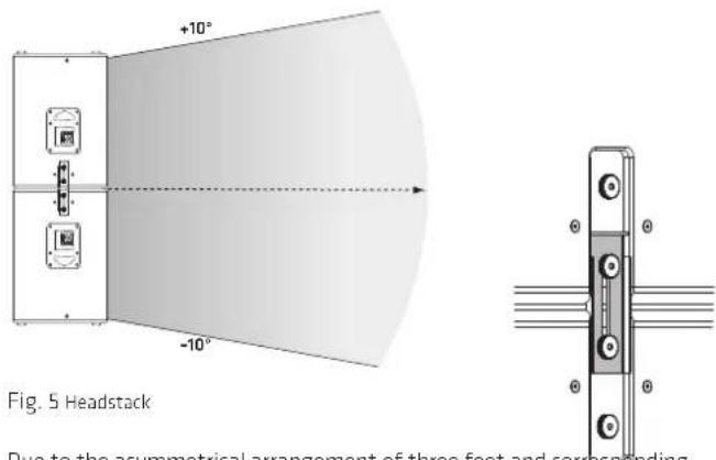
Due to the asymmetrical arrangement of three feet and corresponding milled grooves in the speaker top plates, the two speakers stand on top of each other in a way that prevents them from twisting and shifting. The cabinets are then secured against being pulled apart vertically by using the two sliding plates on the left and right sides of the speaker.
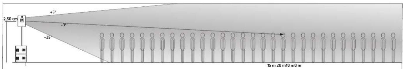
Fig. 3
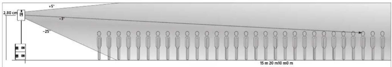
Fig. 4
natural_image
Technical line drawings of server racks and control panels (no text or symbols)Fig. 6
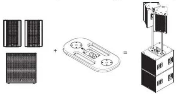
We recommend the following system setup in stacking applications:
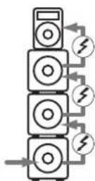
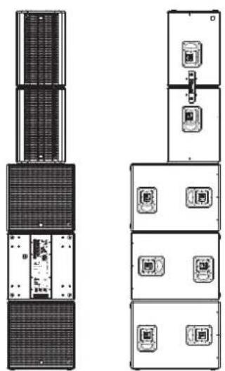
With three LINEAR 5 MK II 118 Sub HPA subwoofers placed one above the other, the headstack consisting of two LINEAR 5 MK II 308 LTAs is placed centrally on the top subwoofer (Fig. 6).
Heads up! Ensure additional tilt protection of the headstack, e.g. by using an M20 threaded bolt (diameter 35 mm) with a minimum length of 50 mm. Screw this onto the M20 thread of the subwoofer and place the speaker flange of the lower LINEAR 5 MKII 308 LTA onto it.
There is also the industry-standard option of securing the headstack using lashing straps.
Cluster
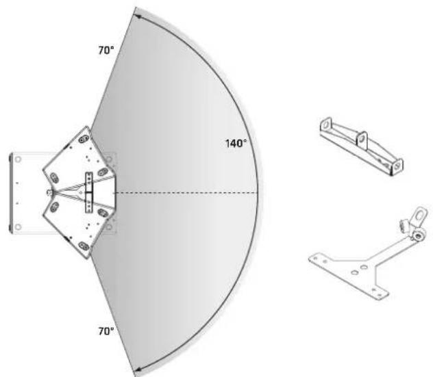
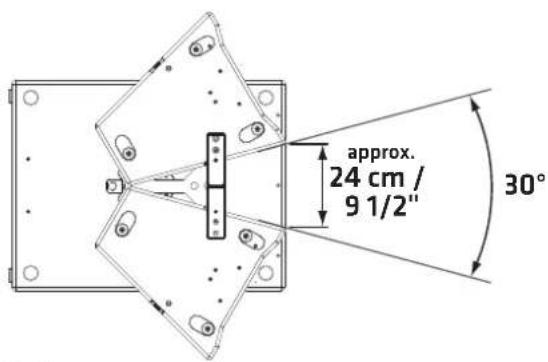
Placing two LINEAR 5 MK II 308 LTAs next to each other to form a cluster extends the horizontal dispersion angle to approximately 140°. This requires a cluster opening angle of 30° (approximately 24 cm, see Fig. 7). This is important to minimise phase cancellation or elevations in the frequency response (phasing effects) (Fig. 8). The use of a cluster is recommended when a wide horizontal dispersion is required. The built-in MCT enables acoustically correct clustering.
(Fig. 7)
To implement this application in rigging operations, a set consisting of a Pick Point and Cluster Plate is optionally available. This offers three attachment points for fastening slings and securing devices (e.g. steel ropes or round slings). At the same time, it protects against unintentional horizontal slippage of the speakers and offers the advantage of a rigid connection between the two cabinets.
We recommend the following system setup in stacking applications:
If three LINEAR 5 MK II 118 Sub HPAs are placed one above the other, the cluster is placed centrally on the top subwoofer using the DFP double flange plate or the PP-CP Pick-Point Cluster-Plate (Fig. 8). The Cluster Plate must also be secured to the M20 flange of the subwoofer with an M20 screw or the "HK Audio Tilt Unit", for example.
The same applies when using the "headstack cluster".
(Fig. 8)
For additional security, there is also the industry-standard option of securing the cluster using lashing straps.
Headstack Cluster
A headstack cluster is the largest expansion stage of the LINEAR 5 MK II 308 LTA. The combination of headstack and cluster is recommended when a large sound coverage depth with simultaneous wide horizontal dispersion is required. This results in a horizontal dispersion of 140irc and a vertical dispersion of +10irc / -10irc (Fig. 9). Using the PP-CP ensures that the correct cluster angle for an acoustically correct cluster ring is fixed. At the same time, the PP-CP provides the rigging points to rig the cluster of 4 using a steel cable or chain.
natural_image
Technical line drawings of a mechanical or electrical component assembly, showing front, side, and top views with no visible text or symbols.(Fig. 9)
4 Setting Up Speakers
- Setup on stands and mounting poles
flowchart
graph TD
    A["输入"] --> C["处理 Unit"]
    B["输入"] --> C["处理 Unit"]
General Information about Setting Up with Speaker Stands
Note! Always make sure the speaker stand is on solid footing and be sure to observe the manufacturer's instructions as to its maximum load-bearing capacity.

Take care!
- Use only speaker stands that are stable enough to prevent accidental tipping. Ensure the speaker stand is designed to handle the cabinet's weight. The highest setting on adjustable stands must be limited to prevent the combination of speaker stand and speaker from tipping. This applies when setting up the stand on a flat, horizontal surface.
- When setting up on an uneven or sloping surface, make sure the speaker stand's base is secured to prevent accidental tipping, either by attaching suitable weights to the base or taking other measures to secure the stand.
- The use of any other fixtures or fittings can result in instability that may cause injury.
- Setup with the Tilt-Unit

natural_image
Simple line drawing of a mechanical component inside a circle (no text or symbols)To ensure a safe setup directly on the subwoofers in a stacked configuration, HK Audio offers the Tilt-Unit as an accessory which can be screwed into the M20 mount of the LINEAR 5 MK II 118 Sub HPA just like a mounting pole. It secures the mid/high units from slipping. Heads up! In a stacked setup without the Tilt-Units, the mid/high models must be secured against slipping, e.g. with a lashing strap.
Deploy the LINEAR 5 MK II 118 Sub HPA as you would any other direct radiating subwoofer. However, when using in Cardioid mode, make sure that the basses are not set up next to each other but on top of each other and that there is at least 1 metre distance from walls.
You have two cardioid setups to choose from: Cardioid 1:1 and Cardioid 2:1
Select the proper presets for the given setup on the rear panel of the subwoofer. See section 2, 8 Preset for more on this.
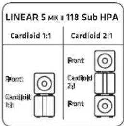
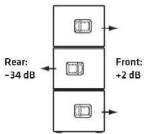
The Cardioid presets attenuate the rearward sound pressure level by up to 34 dB, and boost the forward SPL by around 2 dB.
When does a Cardioid setup make sense?
While medium and high frequencies can be radiated in directional patterns, low frequencies are spherical. This often leads to an unpleasant excess of low bass on and behind the stage. Organisers are also increasingly setting precise demands for sound distribution, for example in marques in city centres. The most effective way to achieve this in the bass range is with Cardioid technology (cancelling out the frequencies radiated to the rear). The 118 Sub HPA therefore meets all the requirements for quickly and easily implementing effective cardioid setups, both mechanically and with the available filter sets.
5 Example systems
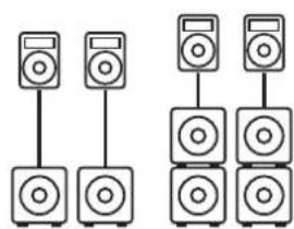
For to ensure the most balanced image possible, centre the subwoofer between the two mid/high units.
5.1 Setting up Speakers on Poles
natural_image
Diagram showing two groups of speakers with different speaker positions, no text or symbols presentIf you wish to place mid/high units on speaker poles rather than stands, simply screw a pole with an M20 thread into the M20 pole mount on the LINEAR 5 MK II 118 Sub HPA.
Presets:
Cardioid system with a speaker pole. The bottom subwoofers are directed to the rear.
Presets:
natural_image
Two identical vertical stack of speakers with different speaker positions (no text or symbols)Cardioid setup as a full stack. The middle subwoofers are directed to the rear.
Presets:
To combine existing LINEAR 5 LTS A mid/high units or other LINEAR speakers with LINEAR 5 MK II 308 LTA or LINEAR 5 MK II 118 Sub HPA, the use of the DSP CONTROL software is required. This allows either the speaker itself to be edited via the Remote Preset or the DSP Out to suit the application combination. A selection of possible combinations with described settings and matching presets can be found at www.hkaudio.com and the corresponding product page.
6 Optional HK Audio Accessories
HK Audio offers protective covers for the LINEAR 5 MK II 308 LTA and 118 Sub HPA models. These protect the speaker during transport. There are also clever stacking and rigging accessories available.
The speaker comes with a Rain Cover Set RCS, which protects the electronics of the 308 LTA and 118 Sub HPA from rain.
Visit the LINEAR 5 MK II product pages at www.hkaudio.com to learn more about the LINEAR 5 MK II accessories.
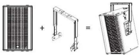
TB-45N
Part number 1007778
The TB-45NQ is a tilt bracket for mounting the LINEAR 5 MK II 308 LTA on truss rods, ceilings, wall brackets, beams and on tripods. Flexible vertical and horizontal alignment is possible. This variant is recommended for installations.
WLL: 70 kg / according to DGUV-V 17: 35 kg
Items delivered: 2 pcs.
natural_image
Three technical diagrams showing a solar panel, a support structure, and a device with internal components (no text or symbols)TB-45NQ
Part number 1007779
The TB-45NQ is a tilt bracket with quick release pins for mounting the LINEAR 5 MK II 308 LTA on truss rods, ceilings, wall brackets, beams and on tripods. Flexible vertical and horizontal alignment is possible. This variant is recommended for mobile use.
WLL: 70 kg / according to DGUV-V 17: 35 kg
Items delivered: 2 pcs.
natural_image
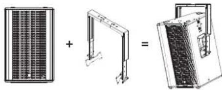
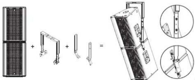
Three technical diagrams showing a solar panel, a mechanical arm, and a device with a grid-patterned panel (no text or symbols)TB-HES Headstack Extension Set
Part number 1007524
The Headstack Extension Set is the extension of the TB-45N or TB-45NQ to accommodate a LINEAR 5 MK II 308 LTA headstack at the correct centre of gravity and tilt point. The TB-HES extends the sides of the TB-45 and connects to the headstack at the free screw points of the sliding plates of the LINEAR 5 MK II 308 LTA speakers.
Items delivered: Set for two tilt brackets
natural_image
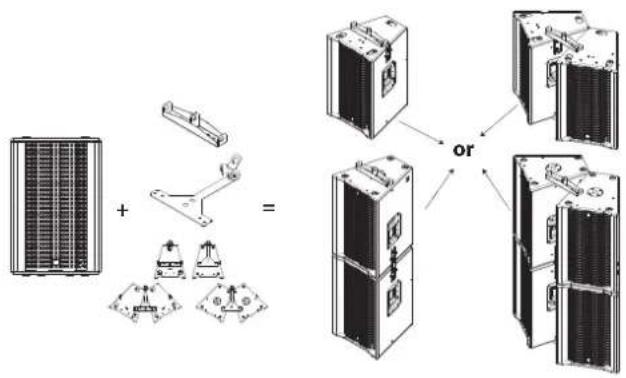
Technical illustration of a mechanical assembly with exploded view and close-up views (no text or symbols)PP-CP Pick Point - Cluster Plate
Part number 1007525
The Pick Point (PP) and the Cluster Plate (CP) provide either two or three attachment points for rigging and angling the LINEAR 5 MK II 308 LTA. The following configurations can be built and rigged with just one set of the PP-CP. 2 x single use, 2 x headstack, 2 x cluster or 2 x headstack cluster. The PP-CP set is therefore a highly universal accessory and offers an unbeatable price/performance ratio.
Items delivered: 2 PP and 2 CP
DFP double flange plate
Part number 1007530
The double flange plate is recommended when a cluster is to be stacked on a LINEAR 5 MK II 118 Sub HPA with mounting poles. This allows the cluster to be easily adjusted to the desired height with two mounting poles and aligned accordingly.
The double flange plate is attached to the flange of the LINEAR 5 MK II 118 Sub HPA with an M20 screw. It has two M20 mounts for two mounting poles or two Tilt-Units, for example. The correct angle of the horizontal cluster (approximately 30° opening angle or approximately 24 cm distance of the side wall at the front) is achieved by screwing the back of the 308 LTA onto the mounting poles or Tilt-Units. In addition, the DFP can be rotated on the subwoofer to align the cluster accordingly. Items delivered: 2 pcs
natural_image
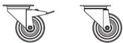
Diagram showing three electronic components: two server racks, a central device with buttons, and a multi-chamber industrial machine (no text or symbols present)Rollers for roller mounting
Part number braked roller 1008068
Part number unbraked rollers 1008069
Suitable rollers for mounting on HK Audio subwoofers. Available in braked and unbraked versions.
natural_image
Two identical diagrams of a mechanical device with circular wheels and a handle, shown side by side (no text or symbols)Protective Cover LINEAR 5 MK II 118 Sub HPA
Part number 1008180
Padded protective transport cover to be used in conjunction with roller mounting. Simply tilt the subwoofer backwards and slip the protective cover over the top of it. This leaves the side with the electronics and any mounted rollers free.
Protective Cover LINEAR 5 MK II 308 LTA
Part number 1007521
Padded protective transport cover for the 308 LTA or LTS / A. It protects the cabinet during transport and can be removed when the speaker is in operation.
CS-WB1 Cover
Part number 1007702
The practical protective cover protects a stack of two 118 Sub HPAs in combination with the CS-WB 1 wheelboard during transport. Cannot be used with only one subwoofer. Cover must be removed during operation.
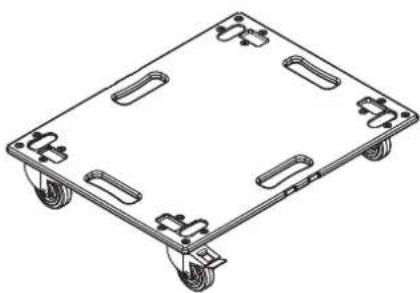
CS-WB1
Part number 1007700
The CS-WB 1 wheelboard has a corresponding mount for the LINEAR 5 MK II 118 Sub HPA and the CS 118. Either one or two subwoofers can be transported and fastened on it. It comes with a tensioning strap for secure fixing. If two subwoofers are stacked, the CS-WB 1 cover can be used for protection during transport. If 118 Sub HPAs are used, the protective cover must be removed while playing. If CS 118s are used, the protective cover does not need to be removed while playing.
natural_image
Isometric line drawing of a four-wheeled cart with wheels and side brackets (no text or symbols)Mounting pole with crank
Part number 1007526
Stable K&M mounting pole with convenient height adjustment by hand crank and ring lock to lock the speaker.
7 Technical Specifications
| Model | LINEAR 5 MK II 308 LTA | LINEAR 5 MK II 118 Sub HPA |
| Max. SPL @ 10 % THD 133 dB half space | (100 Hz - 12 kHz averaged) | 129 dB half space(36 Hz - 100 Hz averaged) |
| Max. SPL Peak @ 10 % THD 138 dB half space 13 dB half space | ||
| Frequency response +/-3 dB 105 Hz - 17 kHz 36 Hz - X-over | ||
| Frequency response -10 dB 98 Hz - 19 kHz 33 Hz - X-over | ||
| Power amp output (RMS/Peak) 600 / 1,200 W 1,500 / 3,000 W | ||
| Amplifier type Class D - bi-amped Class D | ||
| Woofer | - | 1 x 18", 4" voice coil |
| Low/mid speaker | 3 x 8", 1.5" voice coil | - |
| HF driver | 1" compression driver, 1.7" voice coil | - |
| Horn characteristics | 60° x +5/-25° MCT horn | - |
| Active x-over frequency | 1.6 kHz FIR X-over with 60 dB/oct. | - |
| Maximum input level | 20 dBu | 20 dBu |
| Analogue inputs | 1 x XLR combo balanced | 2 x XLR combo balanced |
| Analogue Thru | 1 x XLR balanced | 2 x XLR balanced |
| DSP Out | 1 x XLR balanced | 1 x XLR balanced |
| Network port EtherCON RJ45, 1 x In, 1 x Thru | EtherCON RJ45, 1 x In, 1 x Thru | |
| Filter presets | Single, Cluster, Headstack, Remote | Front, Cardioid 1:1 vertical, Cardioid 2:1 vertical, Remote |
| Remote software | DSP CONTROL (Windows, Mac OS) | DSP CONTROL (Windows, Mac OS) |
| DSP functions | Fully parametric 10-band EQ with variable filter characteristics, High-Pass Filter, Low-Pass Filter, Polarity, Level, Delay, Limiter, Mute | Fully parametric 10-band EQ with variable filter characteristics, Low-Pass Filter, Polarity, Level, Delay, Limiter, Mute |
| Sample rate | 48 kHz | 48 kHz |
| System latency | <= 2.9 ms | <= 2.6 ms |
| Mains connection | 1 x PowerCon NAC3 In, 1 x PowerCon NAC3 Thru, 100-240 V | 1 x PowerCon NAC3 In, 1 x PowerCon NAC3 Thru, 100-240 V |
| Power consumption | 1 A / 100-240 V nominal according to EN 62368-1 | 2.5 A / 100-240 V nominal according to EN 62368-1 |
| Setup angle | - | - |
| Pole mount | MonoTilt 0° | 1 x M20 |
| Rigging points | 5 x M8 (AP-8) | - |
| Carrying handles | 2 x MultiGrip | 4 x MultiGrip |
| Housing | Birch multiplex Birch multiplex | |
| Surface | Black acrylic enamel | Black acrylic enamel |
| Front grille | 2 mm metal grille backed with black acoustic foam | 2 mm metal grille backed with black acoustic foam |
| Dimensions (WxHxD) | 44 x 68 x 46 cm17-21/64 x 26-49/64 x 189-7/64" | 61 x 61 x 79 cm24-1/64 x 24-1/64 x 31-7/64" |
| Weight | 25 kg / 55.1 lbs 53.4 kg / 117.2 lbs |
LTA headstack system with PowerCon: 4 x LINEAR 5 MKII 308 LTA
natural_image
Technical line drawing of a mechanical enclosure with internal compartments and ventilation ducts (no text or symbols)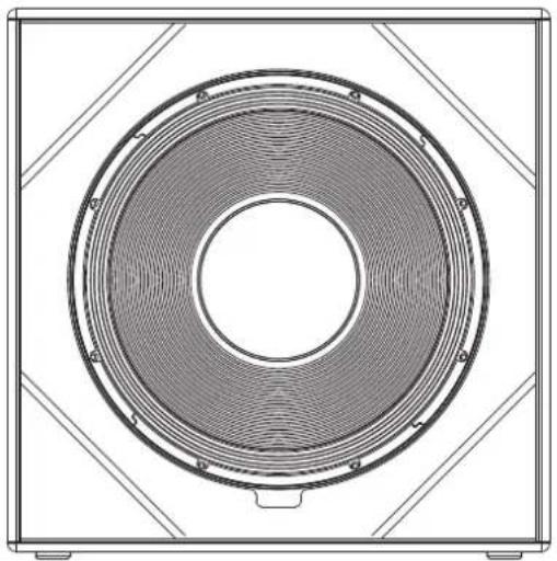
natural_image
Technical line drawing of a circular speaker or fan component with concentric rings and mounting brackets (no text or symbols)Abb.: 5 Headstack
natural_image
Technical line drawings of server racks and control panels (no text or symbols)Abb.: 6
(Abb.:7)
(Abb.: 8)
natural_image
Technical line drawings of a mechanical or electrical component with three views: top shows a curved fan-like structure, middle shows a semi-circular fan with internal components, and right shows a side-view of a multi-chambered device (no text or symbols present)(Abb.: 9)
4Aufstellung
natural_image
Diagram showing two groups of speakers with different speaker positions, connected by lines (no text or labels)natural_image
Two identical vertical stacks of speakers with speaker icons, no text or symbols presentnatural_image
Three technical diagrams showing a solar panel, a support structure, and a final device with meshed panels (no text or symbols)TB-45NQ
Artikel Nr. 1007779
natural_image
Three technical diagrams showing a grid panel, a bracket with a handle, and a final device with a mesh structure (no text or symbols)TB-HES Headstack Extension Set
Artikel Nr. 1007524
PP-CP Pick Point - Cluster Plate
Artikel Nr. 1007525
DFP Doppel-Flansch-Platte
Artikel Nr. 1007530
natural_image
Diagram showing solar panel components and a mechanical device with a central control unit (no text or symbols)Rollen zur Rollenmontage
natural_image
Two identical diagrams of a mechanical device with wheels and a handle, shown from different angles (no text or symbols)Protective Cover LINEAR 5 MK II 118 Sub HPA
Artikel Nr. 1008180
natural_image
Isometric line drawing of a four-wheeled cart with four side slots (no text or symbols)Kurbel Distanzstange
Artikel Nr. 1007526
LTA Headstack-Cluster-System: 4x LINEAR 5 MKII 308 LTA
natural_image
Technical line drawing of a mechanical enclosure with ventilation grilles and internal components (no text or symbols)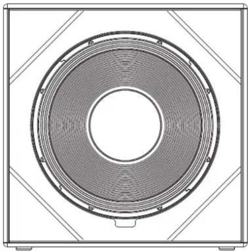
natural_image
Technical line drawing of a speaker grille with concentric rings and mounting brackets (no text or symbols)natural_image
Technical line drawings of server racks and control panels (no text or symbols)Fig. 6
(Fig. 7)
(Fig. 8)
natural_image
Technical line drawing of a mechanical or electrical enclosure with internal grating and mounting brackets (no text or symbols)(Fig. 9)
4Installation
natural_image
Diagram showing two groups of speakers with different speaker positions, connected by lines (no text or symbols present)natural_image
Two identical vertical stacks of speakers, each with a speaker icon and a screen on top (no text or symbols)natural_image
Three technical diagrams showing a grid-patterned panel, a structural bracket, and a simplified device with mesh structure (no text or symbols)TB-45NQ
Code article 1007779
natural_image
Three technical diagrams showing a grid panel, a crane arm, and a mechanical device with a meshed base (no text or symbols)TB-HES Headstack Extension Set
Code article 1007524
natural_image
Technical illustration of a mechanical assembly with exploded and assembled views (no text or symbols)PP-CP Pick Point - Cluster Plate
Code article 1007525
DFP Double Flange Plate
Code article 1007530
natural_image
Diagram showing three types of electronic devices: two solar panels, a control panel with buttons, and a multi-chamber device connected to a rack (no text or symbols present)natural_image
Two identical diagrams of a mechanical component with concentric circles and a handle, shown from different angles (no text or symbols)Housse de protection LINEAR 5 MK II 118 Sub HPA
Code article 1008180
natural_image
Isometric line drawing of a four-wheeled cart with wheels and side brackets (no text or symbols)natural_image
Technical line drawing of a mechanical enclosure with ventilation ducts and internal components (no text or symbols)
natural_image
Technical line drawing of a speaker grille with concentric rings and mounting brackets (no text or symbols)natural_image
Technical line drawings of server racks and control panels (no text or symbols)Fig.: 6
(Fig.: 7)
(Fig.: 8)
natural_image
Technical line drawing of a multi-chamber industrial machine with cooling fins and mounting brackets (no text or symbols)(Fig.: 9)
4Installazione
natural_image
Simple line drawing of a monitor and a camera inside a circle (no text or symbols)natural_image
Diagram showing two groups of speakers with different speaker positions, connected by lines (no text or symbols)natural_image
Two identical vertical stacks of speakers with speaker bodies, no text or symbols presentnatural_image
Three technical diagrams showing a solar panel, a support structure, and a server rack (no text or labels)TB-45NQ
Cod. art 1007779
natural_image
Three technical diagrams showing a solar panel array, a mechanical bracket, and a final device with internal components (no text or symbols)TB-HES Headstack Extension Set
Cod. art. 1007524
PP-CP Pick Point - Cluster Plate
Cod. art. 1007525
Piastra a doppia flangia DFP
Cod. art. 1007530
natural_image
Diagram showing solar panel components and a mechanical device with a central control unit (no text or symbols)natural_image
Two identical diagrams of a mechanical device with circular wheels and a handle, shown from different angles (no text or symbols)Protective Cover LINEAR 5 MK II 118 Sub HPA
Cod. art. 1008180
natural_image
Isometric line drawing of a four-wheeled cart with wheels and side brackets (no text or symbols)natural_image
Technical line drawing of a mechanical enclosure with ventilation ducts and internal components (no text or symbols)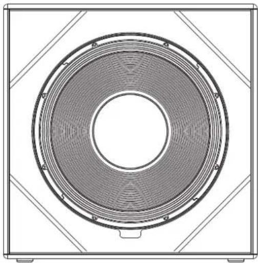
natural_image
Technical line drawing of a speaker grille with concentric rings and mounting brackets (no text or symbols)Fig. 5 Headstack
natural_image
Technical line drawings of server racks and electrical enclosures (no text or symbols)Fig. 6
(Fig. 7)
(Fig. 8)
natural_image
Technical line drawing of a mechanical or electrical enclosure with internal grating and mounting brackets (no text or symbols)(Fig. 9)
natural_image
Simple line drawing of a mechanical component inside a circle (no text or symbols)natural_image
Diagram showing two groups of speakers connected in a row, no text or symbols presentnatural_image
Two identical stacked audio equipment units with speaker bodies, no text or symbols visiblenatural_image
Three technical diagrams showing a grid-patterned panel, a simple bracket, and a simplified device with mesh structure (no text or symbols)TB-45NQ
natural_image
Three technical diagrams showing a grid panel, a bracket with a handle, and a final mechanical component (no text or symbols present)TB-HES Headstack Extension Set
natural_image
Technical illustration of a mechanical assembly with exploded view and close-up views (no text or symbols)PP-CP Pick Point - Cluster Plate
DFP double flange plate
natural_image
Diagram showing solar panel components and a mechanical device with a central control panel (no text or symbols)natural_image
Two identical diagrams of a mechanical device with wheels and a handle, shown from different angles (no text or symbols)natural_image
Isometric line drawing of a four-wheeled cart with four side slots (no text or symbols)
- LINEAR 5 MK II
- Important Safety Instructions! Read before connecting!
- General Notes on Safety for Loudspeaker Systems
- Welcome to the HK Audio family!
- Your HK Audio Team
- Warranty
- HK Audio
- General Information
- Items delivered
- Connections and controls
- 2
- Thru
- Gain
- Input/Limiter LED
- DSP Out
- Ethernet In /Thru
- Data
- Preset
- Power
- Power LED
- Mains Input
- Link
- Auto Sleep
- Alignment
- Single
- Headstack
- Cluster
- Headstack Cluster
- Setting Up Speakers
- General Information about Setting Up with Speaker Stands
- Take care!
- When does a Cardioid setup make sense?
- Example systems
- Setting up Speakers on Poles
- Optional HK Audio Accessories
- TB-45N
- TB-45NQ
- TB-HES Headstack Extension Set
- PP-CP Pick Point - Cluster Plate
- DFP double flange plate
- Rollers for roller mounting
- Protective Cover LINEAR 5 MK II 118 Sub HPA
- Protective Cover LINEAR 5 MK II 308 LTA
- CS-WB1 Cover
- CS-WB1
- Mounting pole with crank
- 4Aufstellung
- DFP Doppel-Flansch-Platte
- Rollen zur Rollenmontage
- Kurbel Distanzstange
- 4Installation
- Housse de protection LINEAR 5 MK II 118 Sub HPA
- 4Installazione
- Piastra a doppia flangia DFP
Brand : HK AUDIO
Model : Linear 5 MK II 118 Sub A
Category : Subwoofer