USER MANUAL iMow RMI 422 STIHL
STIHL RMI 422, RMI 422 P, RMI 422 PC
STIHL
DE Gebrauchsanleitung
EN Instruction manual
FR Manuel d'utilisation
NL Gebruiksaanwijzing
IT Istruzioni per l'uso
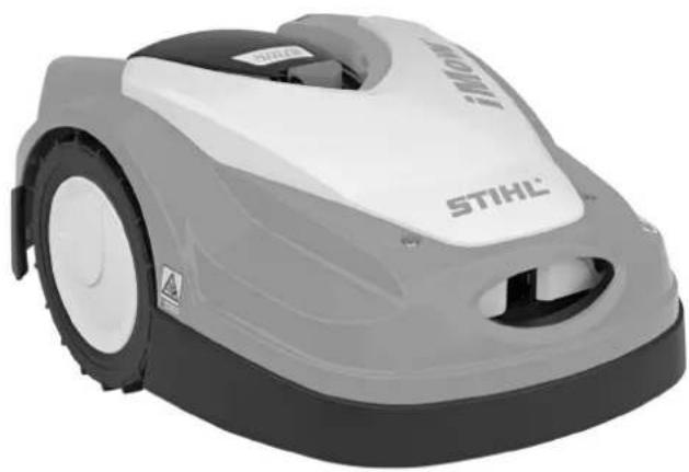
natural_image
Exterior view of a StiHL robotic car (no visible text or symbols on body)
RMI 422.0 RMI 422.0 P RMI 422.0 PC
C
EUR 1



Dockingstation (ADO) 73
RMI 422 P, RMI 422 PC:
Interne Dockingstation:
Externe Dockingstation:
natural_image
Technical diagram of a car interior showing dashboard and steering wheel (no text or symbols)
natural_image
Technical line drawing of a mechanical assembly with labeled component '1' (no text or symbols beyond label)
natural_image
Technical line drawing of three mechanical components: a spool, a pin-like tool, and a connector (no text or symbols present)
natural_image
Technical line drawing of a mechanical assembly with labeled parts (no readable text or symbols)
natural_image
Diagram of a cell with labeled organelles, showing a nucleus and electron shell (no text or symbols present)

iMow mäht den Rasen
The image contains a graphical representation of a patterned bar or bar with vertical bars, which are likely part of a standard diagram such as a line graph or a ruler. There is no textual content to extract.

5. Status Funkmodul (RMI 422 PC):
11. Energiemodus (RMI 422 PC):
3. GPS-Schutz (RMI 422 PC):
natural_image
Technical line drawing of a mechanical component with no visible text or symbols
natural_image
Technical line drawing of a mechanical assembly with labeled component 'F' (no text or symbols beyond label)
natural_image
Diagram of a mechanical device with labeled parts and an upward arrow indicating motion (no text or symbols present)
natural_image
Technical line drawing of a mechanical device with labeled component (no text or symbols present)
natural_image
Line drawing of a human figure holding a mechanical device (no text or symbols)
natural_image
Line drawing of a mechanical device with intersecting rods and a central body (no text or symbols)
RMI 422.0, RMI 422.0 P, RMI 422.0 PC:
natural_image
Simple line drawing of a mechanical component with a cylindrical top and rectangular base (no text or symbols)
Nächster Service
Datum: ____ ____ ____ ____ ____
Thank you for choosing STIHL. We develop and manufacture our quality products to meet our customers' requirements. The products are designed for reliability even under extreme conditions.
STIHL also stands for premium service quality. Our specialist dealers guarantee competent advice and instruction as well as comprehensive service support.
We thank you for your confidence in us and hope you will enjoy working with your STIHL product.
Dr. Nikolas Stihl
IMPORTANT: READ BEFORE USE AND KEEP IN A SAFE PLACE.
1. Table of contents
Notes on the instruction manual 92
General 92
Country-specific versions 92
Instructions for reading the instruction manual 92
Machine overview 94
Robotic mower 94
Docking station 95
Display 96
How the robotic mower works 97
Operating principle 97
Safety devices 98
STOP button 98
Disabling device 98
Protective covers 98
Impact sensor 98
Lifting protection 99
Tilt sensor 99
Display illumination 99
Anti-theft alarm 99
GPS protection 99
For your safety 99
General 99
Clothing and equipment 100
Warning – dangers caused by electrical current 101
Battery 101
Transporting the machine 101
Before initial operation 102
Programming 103
During operation 103
Maintenance and repairs 104
Storage for prolonged periods without operation 105
Disposal 105
Description of symbols 105
Standard equipment 106
Initial installation 106
Notes on the docking station 106
Docking station connections 108
Connecting the power cable to the docking station 109
Installation material 110
Adjusting the cutting height 110
Notes on initial installation 110
Setting the language, date and time 111
Installing the docking station 112
Routing the perimeter wire 113
Connecting the perimeter wire 116
Linking the robotic mower and docking station 119
Checking the installation 121
Programming the robotic mower 122
Completing initial installation 123
First mowing operation after initial installation 123
iMow app 123
Operating instructions 124
Status screen 125
Information area 126
Main menu 127
Commands 127
Mowing plan 128
Active times 129
Mowing duration 129
Information 130
Settings 131
iMow – machine settings 131
Setting the rain sensor 131
Setting the status screen 132
Installation 132
Setting starting points 133
Safety 134
Service 135
Perimeter wire 135
Planning routing of the perimeter wire 136
Making a sketch of the mowing area 136
Routing the perimeter wire 137
Connecting the perimeter wire 137
Wire clearances - use iMow Ruler 137
Acute corners 138
Confined areas 138
Installing linking sections 139
No-go areas 139
Secondary areas 140
Corridors 140
Guide loops for offset drive home 142
Accurate mowing along edges 143
Sloping terrain in the mowing area 143
Installing reserve wire 144
Using wire connectors 144
Narrow edge clearances 145
Docking station 145
Docking station controls 145
Notes on mowing 146
General 146
Mulching 146
Active times 146
Mowing duration 146
Home area (RMI 422 PC) 147
Operating the machine 147
Preparation 147
Flap 147
Adapting the programming 147
Automatic mowing 148
Mowing independently of active times 148
Docking the robotic mower 149
Charging the battery 149
Maintenance 150
Maintenance schedule 150
Cleaning the machine 150
Checking the mowing blade wear limits 151
Removing and installing the mowing blade 151
Sharpening the mowing blade 152
Removing and installing the carrier plate 152
Finding a wire break 153
Storage and winter break 154
Removing the docking station 154
Standard spare parts 155
Accessories 155
Minimising wear and preventing damage 155
Environmental protection 156
Removing the battery 156
Transport 158
Lifting or carrying the machine 158
Securing the machine (lashing) 158
EU - Declaration of conformity 158
Robotic mower, automatic and cordless (RMI) with docking station (ADO) 158
Technical specifications 159
Messages 160
Troubleshooting 167
Service schedule 170
Handover confirmation 170
Service confirmation 170
Installation examples 171
2. Notes on the instruction manual
2.1 General
This instruction manual constitutes original manufacturer's instructions in the sense of EC Directive 2006/42/EC.
STIHL is continually striving to further develop its range of products; we therefore reserve the right to make alterations to the form, technical specifications and equipment level of our standard equipment.
For this reason, the information and illustrations in this manual are subject to alterations.
This instruction manual may describe models that are not available in all countries.
This instruction manual is protected by copyright. All rights reserved, especially the right of reproduction, translation and processing using electronic systems.
2.2 Country-specific versions
STIHL supplies machines with different plugs and switches, depending on the country of sale.
Machines with European plugs are shown in the illustrations. Machines with other types of plug are connected to the mains in a similar way.
2.3 Instructions for reading the instruction manual
Illustrations and texts describe specific operating steps.
All symbols which are affixed to the machine are explained in this instruction manual.
Viewing direction:
Viewing direction when "left" and "right" are used in the instruction manual: the user is standing behind the machine and is looking forwards in the direction of travel.
Section reference:
References to relevant sections and subsections for further descriptions are made using arrows. The following example shows a reference to a section: ( 3.)
Designation of text passages:
The instructions described can be identified as in the following examples.
Operating steps which require intervention on the part of the user:
- Release bolt (1) using a screwdriver, operate lever (2)...
General lists:
– Use of the product for sporting or competitive events
Texts with added significance:
Text passages with added significance are identified using the symbols described below in order to especially emphasise them in the instruction manual:

Danger
Risk of accident and severe injury to persons. A certain type of behaviour is necessary or must be avoided.

Warning
Risk of injury to persons. A certain type of behaviour prevents possible or probable injuries.

Caution
Minor injuries or material damage can be prevented by a certain type of behaviour.

Note
Information for better use of the machine and in order to avoid possible operating errors.
Texts relating to illustrations:
Some Illustrations which are necessary for use of the machine can be found at the front of this instruction manual.
The camera symbol serves to link the figures on the illustration pages with the corresponding text passages in the instruction manual.

Illustrations with text passages:
Operating steps relating directly to the illustration can be found immediately after the illustration, with a corresponding reference to the item numbers.
Example:
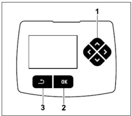
The control pad (1) serves for navigation in the menus. Settings are confirmed and menus opened using the OK button (2). Menus can be exited again using the Back button (3).
3. Machine overview
3.1 Robotic mower
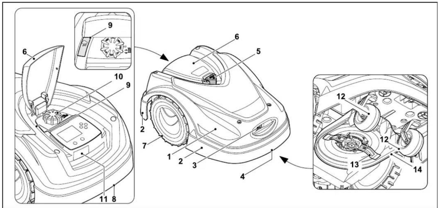
1 Movably mounted hood ( 5.4),
( 5.5)
2 Impact protector
3 Charging contacts:
Connecting contacts to docking
station
4 Front carrying handle (integrated in the movable hood) ( 21.1)
5 STOP button ( 5.1)
6 Flap ( 15.2)
7 Drive wheel
8 Rear carrying handle (integrated in the movable hood) ( 21.1)
9 Rain sensor ( 11.12)
10 Rotary handle for cutting height adjustment ( 9.5)
11 Identification plate with machine number
12 Front wheel
13 Dual-ground mowing blade ( 16.4)
14 Mowing deck
3.2 Docking station
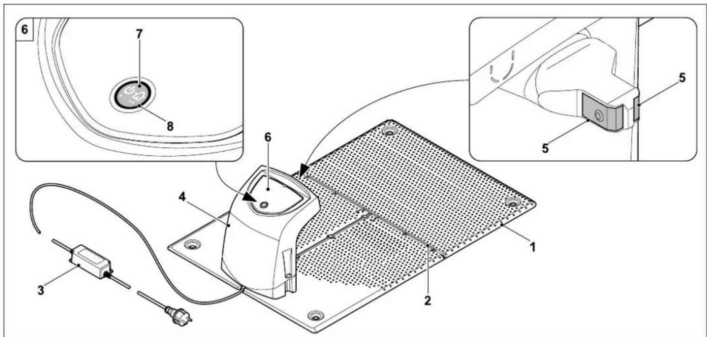
1 Floor plate
2 Cable guides for retaining the perimeter wire ( 9.10)
3 Power supply unit
4 Removable cover ( 9.2)
5 Charging contacts: connecting contacts to robotic mower
6 Control panel
with button and LED ( 13.1)
7 Button
8 LED display
3.3 Display
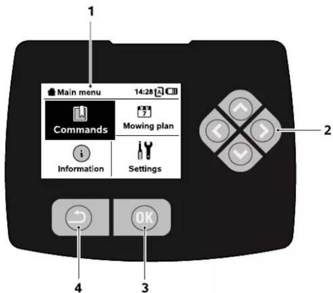
1 Graphical display
2 Control pad:
navigating in menus ( 11.1)
3 OK button:
navigating in menus ( 11.1)
4 Back button: navigating in menus
4. How the robotic mower works
4.1 Operating principle
flowchart
graph TD
    A["Stage 1"] --> B["Stage 2"]
    B --> C["Stage 3"]
    C --> D["Stage 4"]
    D --> E["Stage 5"]
    E --> F["Output"]
    style A fill:#f9f,stroke:#333
    style B fill:#f9f,stroke:#333
    style C fill:#f9f,stroke:#333
    style D fill:#f9f,stroke:#333
    style E fill:#f9f,stroke:#333
    style F fill:#f9f,stroke:#333
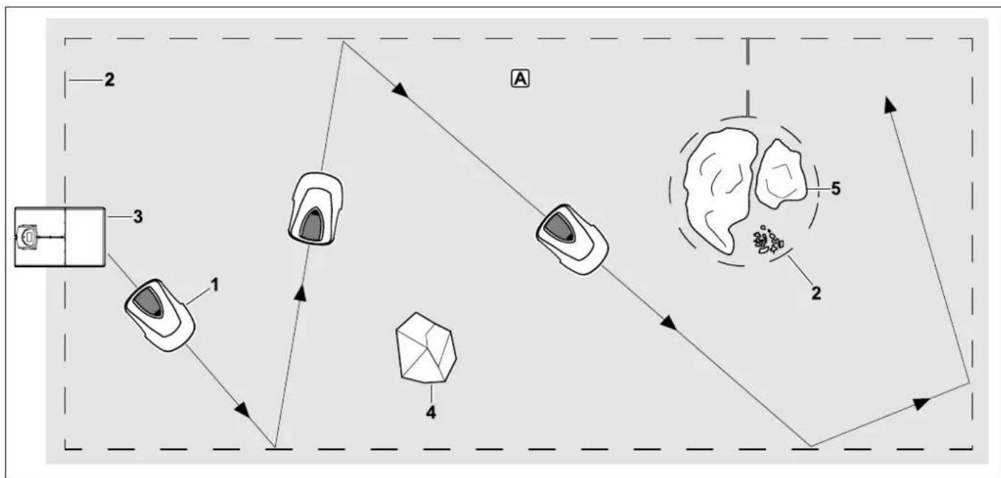
The robotic mower (1) is designed for the automatic mowing of lawns. It mows the lawn in randomly selected paths.
In order for the robotic mower to detect the borders of the mowing area A, a perimeter wire (2) must be routed around that area. A signal generated by the docking station (3) flows through this perimeter wire.
Solid obstacles (4) in the mowing area are reliably detected by the robotic mower by means of an impact sensor. Areas (5) that the robotic mower is not to enter and obstacles that need to be avoided must be separated from the mowing area using the perimeter wire.
When automatic mowing is switched on, the robotic mower independently leaves the docking station and mows the lawn during the active times set ( 14.3). The robotic mower automatically travels to the docking station to recharge the battery. The number and duration of the mowing and charging
operations within the active times are adapted automatically. This guarantees that the required weekly mowing duration is always achieved.
When automatic mowing is switched off and for mowing operations independent of the active times, a mowing operation can be activated using the command "Start mowing" or "Start time-delayed mowing". ( 11.5)

The STIHL robotic mower can be operated reliably and without interference in close vicinity to other robotic mowers. The wire signal meets the EGMF (European Garden
Machinery Federation) standard with regard to electromagnetic emissions.
5. Safety devices
The machine is equipped with several safety devices for safe operation and for the prevention of improper use.

Risk of injury!
If a safety device is found to be defective, the machine must not be operated. Consult a specialist dealer; STIHL recommends STIHL specialist dealers.
When the red STOP button on the top of the robotic mower is pressed, operation of the machine is stopped immediately. The mowing blade comes to a standstill within a few seconds and the message "STOP button pressed" appears on the display. The robotic mower cannot be operated and is safe while the message is active. ( 24.)
When automatic mowing is switched on, following
confirmation of the message with OK, the system enquires whether automatic operation is to be continued.
If the response is Yes, the robotic mower continues to mow the lawn in accordance with the mowing plan.

If the response is No, the robotic mower remains stationary in the mowing area and automatic mowing is switched off. ( 11.5)

Pressing and holding the STOP button also activates the disabling device. ( 5.2)
5.2 Disabling device
The robotic mower must be disabled prior to any maintenance or cleaning work, prior to transportation and prior to inspection.
The robotic mower cannot be operated when the disabling device is activated.

Activating the disabling device:
- Press and hold the STOP button
– in the Commands menu,
– in the Safety menu.
Activating the disabling device via the Commands menu:
- In the "Commands" menu, select the "Lock iMow" entry and confirm with the OK button. ( 11.5)
- Open the "Safety" submenu in the "Settings" menu. ( 11.16)
- Select the "Disab. device" entry and confirm with the OK button.
Deactivating the disabling device:
- When required, wake up the machine by pressing any button.
- Unlock the robotic mower using the illustrated button combination. For this purpose, press the OK button and the Back button in the sequence shown on the display.

5.3 Protective covers
The robotic mower is equipped with protective covers that prevent inadvertent contact with the mowing blade and the clippings.
These include, in particular, the hood.
5.4 Impact sensor
The robotic mower is equipped with a movable hood which serves as an impact sensor. During automatic operation, it immediately comes to a standstill if it comes into contact with a solid obstacle which has a specific minimum height (8 cm) and is firmly attached to the ground. It then turns to face another direction and continues mowing. If the impact sensor is triggered too frequently, the mowing blade is also stopped.

Impacts against obstacles occur with a certain force. Sensitive obstacles, e.g. light objects such as small flower pots, can therefore be knocked over or damaged.
STIHL recommends removing obstacles or blocking them off by means of no-go areas. ( 12.9)
5.5 Lifting protection
If the robotic mower is lifted by the hood, mowing is stopped immediately. The mowing blade comes to a standstill within a few seconds.
5.6 Tilt sensor
If the permissible slope inclination is exceeded during operation, the robotic mower immediately changes its direction of travel. In the event of a rollover, the wheel drive and mowing motors are switched off.
5.7 Display illumination
The display illumination is activated during operation. Thanks to this illumination, the robotic mower is easily recognisable, even in darkness.
5.8 Anti-theft alarm
When the anti-theft alarm is activated, an alarm signal sounds when the robotic mower is lifted unless the PIN code is entered within one minute. ( 11.16)
The robotic mower can only be operated in conjunction with the docking station supplied. A further docking station must be linked with the robotic mower. ( 11.16)

STIHL recommends that one of the safety levels "Low", "Medium" or "High" be set. This ensures that unauthorised persons cannot operate the robotic mower using other docking stations and are unable to change settings or the programming.
5.9 GPS protection
The model RMI 422 PC is equipped with a GPS receiver. When GPS protection is activated, the owner of the machine is notified if the machine is operated outside the home area. The PIN code is also requested on the display. ( 14.5)

Recommendation:
Always activate GPS protection.
(⇒ 11.16)
6. For your safety
6.1 General

These safety regulations must be observed when working with the machine.

Read the entire instruction manual before using the machine for the first time. Keep the instruction manual in a safe place for future reference.
These safety precautions are essential for your safety, however the list is not exhaustive. Always use the machine in a reasonable and responsible manner and be aware that the user is responsible for accidents involving third parties or their property.
The term "use" covers all work on the robotic mower, the docking station and the perimeter wire.
A "User" is defined as:
– A person who reprograms the robotic mower or changes the existing programming.
– A person who performs work on the robotic mower.
– A person who activates or operates the machine.
- A person who installs or removes the perimeter wire or docking station.
The use of the iMow app also falls under the term "use" for the purpose of this instruction manual.
The machine must only be operated by persons who are well rested and in good physical and mental condition. If your health is impaired, you should consult your doctor to determine whether working with the machine is possible. The machine should not be operated after the consumption of alcohol, drugs or medications which impair reactions.
Make sure that you are familiar with the controls and use of the machine.
The machine must only be used by persons who have read the instruction manual and are familiar with operation of the machine. The user should seek expert and practical instruction prior to initial operation. The user must receive instruction on safe use of the machine from the vendor or another expert.
During this instruction, the user should be made aware that the utmost care and concentration are required for working with the machine.
Residual risks persist even if you operate this machine according to the instructions.

Risk of death from suffocation!
Packaging material is not a toy - danger of suffocation! Keep packaging material away from children.
Only give or lend the machine to persons who are familiar with this model and how to operate it. The instruction manual forms part of the machine and must always be provided to persons operating it.
Make sure that the user is physically, sensorily and mentally capable of operating the machine and working with it. If the user is physically, sensorily or mentally impaired, the machine must only be used under supervision or following instruction by a responsible person.
Make sure that the user is of legal age or being trained under supervision in a profession in accordance with national regulations.

Caution - risk of accident!

Children must be kept away from the machine and mowing area during mowing operation.

Dogs and other pets must be kept away from the machine and mowing area during mowing operation.
For safety reasons, any modification to the machine, except the proper installation of accessories or attachments approved by STIHL, is forbidden and results in voiding of the warranty cover. Information regarding approved accessories and attachments can be obtained from your STIHL specialist dealer.
In particular, any tampering with the machine which increases the power output or speed of the motors is forbidden.
It is not permissible to make any modifications to the machine that could lead to increased noise emissions.
For safety reasons, the machine software must never be modified or tampered with.
Particular care is required during use in public green spaces, parks, sports fields, along roads and in agricultural and forestry businesses.
It is not permitted to transport objects, animals or persons, particularly children, on the machine.
Never allow persons, particularly children, to ride or sit on the robotic mower.
Caution – risk of accident:
The robotic mower is intended for automatic lawn care. Its use for other purposes is not permitted and may be dangerous or result in damage to the machine.
Due to the physical danger to the user, the machine must not be used for the following applications (incomplete list):
– for trimming bushes, hedges and shrubs,
– for cutting creepers,
– for the care of lawn roofs and balcony boxes,
– for shredding or chipping tree or hedge cuttings,
– for clearing paths (vacuuming, blowing),
– for levelling earth mounds, e.g. mole hills.
6.2 Clothing and equipment

Wear sturdy footwear with high-grip soles and never work barefoot or when wearing e.g.
sandals,
- when approaching the robotic mower during operation.

Wear suitable work clothes during installation, maintenance operations and all other work on the machine and docking
station.
Never wear loose clothes which may become caught on moving parts – do not wear jewellery, ties or scarves.
In particular, wear long trousers
– when approaching the robotic mower during operation.

Always wear thick gloves during maintenance and cleaning operations, when laying and removing wires and when
securing the docking station.
In particular, protect the hands when working on the mowing blade and when driving in the fixing pins or the docking station pegs.
Long hair must always be tied up and secured (headscarf, cap, etc.) when working on the machine.

Suitable safety glasses must be worn when driving in the fixing pins and the docking station pegs.
6.3 Warning – dangers caused by electrical current

Warning: Risk of electric shock!
Particularly important for electrical safety are an intact power cable and mains plug on the power supply unit. Damaged cables, connectors and plugs, or electric cables that do not conform to regulations must not be used, to prevent any risk of electric shocks.
Therefore, check the electric cable regularly for signs of damage or ageing (brittleness).
Only use an original power supply unit.
The power supply unit must not be used:
- if it is damaged or worn,
- if the cables are damaged or worn. Check the power cable in particular for damage and ageing.
Maintenance and repair work on power cables and power supply units must only be performed by specially qualified technicians.
Danger of electric shock!
Do not connect a damaged cable to the mains and only touch a damaged cable once it has been disconnected from the mains.
The electric cable on the power supply unit must not be modified (e.g. shortened). The cable between the power supply unit and docking station must not be extended.
The power supply unit and cable must not be left on wet ground for prolonged periods.
Danger of electric shock!
Damaged cables, connectors and plugs, or electric cables which do not conform with regulations may not be used.
Always ensure that the power cables used are adequately protected by a fuse.
Detach electric cables at the plug and socket and not by pulling on the electric cable.
Only connect the machine to a power supply that is protected by means of a residual current-operated protective device with a release current of a maximum of 30 mA. Your electrician can provide further information.
If the power supply unit is connected to the mains supply outside a building, the socket must be approved for outdoor use. Your electrician can provide further information about country-specific legislation.
It must be noted that current fluctuations can damage the machine when it is connected to a power generator.
6.4 Battery
Only use genuine batteries.
The battery is intended exclusively for fixed installation in a STIHL robotic mower. It is optimally protected there and is charged when the robotic mower is in the docking station. No other charger must be used. The use of an unsuitable charger can result in danger due to electric shock, overheating or escaping corrosive battery fluid.
Never open the battery.
Do not drop the battery.
Never use a defective or deformed battery.
Store the battery out of the reach of children.

Explosive hazard!
Protect the battery against direct sunlight, heat and fire – never throw it into a fire.

Only use or store the battery at temperatures from -10^ to max. +50^ .
Protect the battery against rain and moisture – do not immerse in liquids.


Do not subject the battery to microwaves or high pressure.
Never connect the battery terminals with metallic objects (short-circuit). The battery can be damaged through short circuits.
Keep the unused battery away from metallic objects (e.g. nails, coins, jewellery). Do not use metallic transport containers – explosive and fire hazard!
Fluid may escape from the battery due to improper use – avoid contact! In the case of inadvertent contact, rinse with water. Seek medical attention if the fluid contacts the eyes. Escaping battery fluid can cause skin irritation and burns.
Do not insert any objects in the ventilation slots of the battery.
For further safety instructions, see http://www.stihl.com/safety-data-sheets
6.5 Transporting the machine
Before transporting, and especially before lifting the robotic mower, activate the disabling device. ( 5.2)
Allow the machine to cool down before transporting.
Avoid contact with the mowing blade when lifting and carrying the machine. The robotic mower must only be lifted at both carrying handles. Never reach under the machine.
Take the weight of the machine into account and use suitable loading aids (lifters) if required.
Secure the machine and other machine parts being transported (e.g. docking station) on the load floor using fastening materials (straps, ropes, etc.) of an adequate size at the fastening points described in this instruction manual. ( 21.)
When transporting the machine, always observe regional legislation, especially regarding load security and the transport of objects on load floors.
Do not leave the battery inside a vehicle and never expose it to direct sunlight.
Lithium-ion batteries must be treated with special care during transport. In particular, short-circuit protection must be ensured. Only transport the battery in the robotic mower.
6.6 Before initial operation
It must be ensured that all persons who use the machine are familiar with the instruction manual.
Carefully follow the instructions for installing the docking station ( 9.1) and perimeter wire ( 12.).
The perimeter wire and the power cable must be securely fastened to the ground so that they do not present a tripping
hazard. Avoid routing the perimeter wire and power cable over edges (e.g. edges of pathways or paving stones). When routing the perimeter wire and power cable on ground into which the supplied fixing pins cannot be driven (e.g. paving stones, pathways), a cable duct must be used.
Correct routing of the perimeter wire and power cable must be regularly checked.
To prevent the risk of stumbling, always drive in the fixing pins all the way.
Do not install the docking station in a place where it is difficult to see and could become a tripping hazard (e.g. around the corner of a house).
If possible, install the docking station out of the reach of pests such as ants or slugs – in particular avoid the area around anthills and composting units.
Areas in which the robotic mower cannot operate safely (e.g. due to danger of falling), must be blocked off through appropriate routing of the perimeter wire. STIHL recommends that the robotic mower is only operated on lawns and surfaced paths (e.g. paved drives).
The robotic mower does not detect any sudden drops such as edges, steps, swimming pools or ponds. If the perimeter wire is routed along potential sudden drops, a clearance of at least 1 m must be maintained between the perimeter wire and the danger area for safety reasons.
Regularly inspect the area on which the machine is to be used and remove any sticks, stones, wires, bones and all other foreign objects that could be thrown up by the machine.
After installing the perimeter wire, particularly remove all tools from the
mowing area. Broken or damaged fixing pins must be removed from the lawn and disposed of.
Regularly check the area to be mown for uneven areas and level them out.
Never use the machine with damaged safety devices or with safety devices removed.
The switch and safety devices installed in the machine must not be removed or bypassed.
All faulty, worn or damaged parts must be replaced before using the machine. Replace any illegible or damaged danger signs and warnings on the machine. Your STIHL specialist has a supply of replacement stickers and all the other spare parts.
Before initial operation, it must be ensured
– that the machine is in good operational condition. This means that the covers, guards and the flap must be in place and in good condition.
– that the docking station is in a safe operating condition. Here, all covers must be properly installed and be in good condition.
– that the power supply unit has been connected to a properly installed socket.
– that the insulation of the electric cable and the mains plug on the power supply unit is in good condition.
– that the entire machine (housing, hood, flap, fastening elements, mowing blade, blade shaft, etc.) is neither worn nor damaged.
– that the mowing blade and the blade fastening are in proper condition (secure seating, damage, wear).
(⇒ 16.3)
- that all screws, bolts, nuts and other fastening elements are in place and properly tightened. Tighten any loose screws, bolts and nuts prior to initial operation (observe tightening torques).
Carry out any necessary work or consult a specialist dealer. STIHL recommends STIHL specialist dealers.
6.7 Programming
Observe local regulations regarding permitted operating times for gardening power tools with motors and programme the active times accordingly. ( 14.3)
In particular, programming must also be adapted so that no children, spectators or animals are in the area to be mown during operation.
Changing the programming using the iMow app in the case of model
RMI 422 PC can result in activities that will not be expected by other people. Changes to the mowing plan must therefore be communicated in advance to all affected people.
The robotic mower must not operate at the same time as a sprinkler system. Adapt the programming accordingly.
Ensure that the correct date and the correct time are set on the robotic mower. Correct the settings if necessary. Incorrect values may cause the robotic mower to start up unintentionally.
6.8 During operation

Keep other persons, especially children and animals, out of the danger area.
Never allow children to approach or play with the robotic mower during operation.
Starting a mowing operation using the iMow app in the case of model
RMI 422 PC may not be expected by third parties. Affected people must therefore be notified in advance about possible activity of the robotic mower.
Never allow the robotic mower to operate unattended if you know that animals or persons, particularly children, are in the vicinity.
When operating the robotic mower in public places, signs with the following notice must be affixed around the mowing area:
"Warning! Automatic lawn mower! Keep away from the machine! Children must be supervised!"

Caution – risk of injury!
Never put hands or feet on or underneath rotating parts. Never touch the rotating blade.
Before thunderstorms, or if there is a danger of lightning strikes, disconnect the power supply unit from the mains. The robotic mower must not be operated.
The robotic mower must never be tilted or lifted when a motor is running.
Never attempt to change settings on the machine when one of the motors is running.
RMI 422:
For safety reasons, the machine (RMI 422) must not be used on slopes with an inclination of more than 19,3° (35 %). Risk of injury! A slope inclination of 19,3° corresponds to a vertical height increase of cm at a 100 cm horizontal distance.
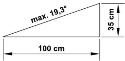
RMI 422 P, RMI 422 PC:
For safety reasons, the machine (RMI 422 P, RMI 422 PC) must not be used on slopes with an inclination of more than 21,8° (40 %).
Risk of injury! A slope inclination of 21,8^ corresponds to a vertical height increase of 40 cm for a 100 cm horizontal distance.
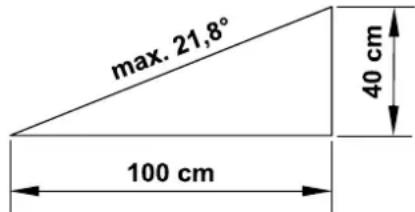

Beware of the cutting tool running on for several seconds before coming to a standstill.
Press the STOP button ( 5.1)
during running operation
– before opening the flap.
Activate the disabling device ( 5.2):
– before lifting or carrying the machine,
– before transporting the machine,
– before removing blockages.
– before carrying out any work on the mowing blade,
– before checking or cleaning the machine,
- after hitting a foreign object or if the robotic mower begins to vibrate excessively. In these cases check the machine, in particular the cutting unit (blade, blade shaft, blade fastening), for damage and carry out the necessary repairs before restarting and working with the machine.

Risk of injury!
Strong vibration is normally an indication of a fault.
In particular, the robotic mower must not be operated with a damaged or bent blade shaft or mowing blade.
If you do not have the appropriate expertise, have the necessary repairs carried out by a specialist dealer (STIHL recommends STIHL specialist dealers).
Before leaving the machine unattended, the safety settings of the robotic mower must be adapted so that it cannot be operated by unauthorised persons. ( 5.)
Do not lean forward and always ensure that you maintain your balance and a firm footing on inclines when operating the machine and its peripherals. Always walk, do not run.
6.9 Maintenance and repairs
Before starting cleaning, repair or maintenance operations, activate the disabling device and park the robotic mower on firm and level ground.
Disconnect the mains plug of the power supply unit before performing any work on the docking station and the perimeter wire.
Allow the robotic mower to cool down for approx. 5 minutes before performing any maintenance operations.
The power cable must only be repaired or replaced by authorised electricians.
Following any work on the machine, check and, if necessary, correct the programming of the robotic mower before putting it back into operation. In particular, the date and time must be set.
Cleaning:
The complete machine must be cleaned carefully at regular intervals. ( 16.2)
Never spray water (particularly using high-pressure cleaners) onto motor components, seals, electric components or bearing points. This may result in damage and expensive repairs.
Do not clean the machine under running water (e.g. using a garden hose).
Do not use aggressive cleaning agents. These can damage plastics and metals, impairing the safe operation of your STIHL machine.


Maintenance operations:
Only maintenance operations described in this instruction manual may be carried out. Have all other work performed by a specialist dealer.
If you do not have the necessary expertise or auxiliary equipment, please always contact a specialist dealer.
STIHL recommends that you have maintenance operations and repairs performed exclusively by a STIHL specialist dealer.
STIHL specialist dealers regularly attend training courses and are provided with technical information.
Only use tools, accessories or attachments approved for this machine by STIHL or technically identical parts. Otherwise, there may be a risk of accidents resulting in personal injury or damage to the machine. If you have any questions, please consult a specialist dealer.
The characteristics of original STIHL tools, accessories and spare parts are optimally adapted to the machine and the user's requirements. Genuine STIHL spare parts can be recognised by the STIHL spare parts number, by the STIHL lettering and, if present, by the STIHL spare parts symbol. On smaller parts, only the symbol may be present.
Always keep warning and information stickers clean and readable. Damaged or missing stickers must be replaced by new, original plates from your STIHL specialist dealer. If a component is replaced with a new component, ensure that the new component is provided with the same stickers.
Only perform work on the cutting unit when wearing thick work gloves and exercising extreme care.
Ensure that all screws and nuts, especially all screws and fastening elements of the cutting unit, are securely tightened, so that the machine is in a safe operating condition.
Check the entire machine for wear or damage on a regular basis, particularly before extended periods when the machine is not in use (e.g. over winter). For safety reasons, worn or damaged parts must be replaced immediately to ensure that the machine is always in a safe operating condition.
Components or guards that are removed for maintenance operations must be properly reinstalled immediately.
6.10 Storage for prolonged periods without operation
Before putting into storage
- Charge the battery (⇒ 15.7)
- Set the highest safety level ( 11.16)
- Activate the disabling device ( 5.2)
Ensure that the machine is protected from unauthorised use (e.g. by children).
Store the machine in good operational condition.
Thoroughly clean the machine before storage (e.g. winter break).
Allow the machine to cool for approx. 5 minutes before storing it in an enclosed space.
The storage room must be dry, frost-free and lockable.
Never store the machine close to naked flames or powerful heat sources (e.g. oven).
6.11 Disposal
Waste products can be harmful to people, animals and the environment. They must consequently be disposed of properly.
Consult your recycling centre or your specialist dealer for information on the proper disposal of waste products. STIHL recommends STIHL specialist dealers.
Ensure that old machines are properly disposed of. Render the machine unusable prior to disposal. In particular, remove the power cable of the power supply unit, as well as the battery of the robotic mower in order to prevent accidents.
Risk of injury due to the mowing blade! Always store an old lawn mower in a safe place prior to scrapping. Ensure that the machine and particularly the mowing blade are kept out of the reach of children.
The battery must be disposed of separately from the machine. Ensure that batteries are disposed of safely and in an environmentally friendly manner.
7. Description of symbols

Warning!
Read the instruction manual before initial use.
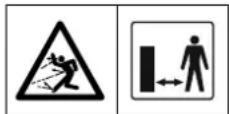
Warning!
Keep a safe distance from the machine during operation.
Keep other persons out of the danger area.
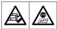
Warning!
Disable the machine before lifting it and before working on it.
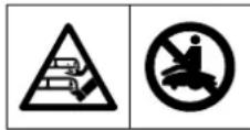
Warning!
Do not climb onto or sit on the machine.
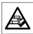
Warning!
Never touch the rotating blade.

Warning!
Keep children away from the machine and mowing area during mowing operation.
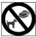
Warning!
Keep dogs and other pets away from the machine and mowing area during mowing operation.
- Standard equipment
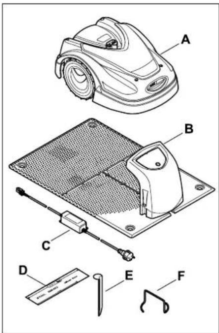
Item Designation Qty.
A Robotic mower 1
B Docking station 1
C Power supply unit 1
D iMow Ruler 2
Item Designation Qty.
E Peg for docking station 4
| F Puller for carrier plate | 1 | |
| - Instruction manual | | 1 |
| - Corridor template | | 1 |
9. Initial installation
For a quick, easy and robust installation, read and comply with the specifications and instructions, especially the wire clearance of 28 cm during routing. ( 12.)
It is possible to increase the mown area by routing the perimeter wire closer to the edge. ( 12.17) For reliable operation, the wire clearance must be adapted to the on-site conditions during routing.
9.1 Notes on the docking station
Requirements for the docking station location:
- Protected, shady.
Direct sunlight can lead to increased temperatures in the machine and longer battery charging times.
A canopy top available as an accessory can be mounted on the docking station. This provides better protection for the robotic mower against the weather.
- Easily visible.
The docking station should be easily visible in its chosen location to prevent the risk of tripping over it.
The mains connection must be close enough to the docking station that the respective power cables can be connected to both the docking station and the mains connection – do not change the power cable of the power supply unit.
A socket with overvoltage protection is recommended.
– Free from sources of interference.
Metal, iron oxides and magnetic or electrically conductive materials as well as old perimeter wire installations can interfere with the mower's operation. It is recommended to remove these sources of interference.
- Level and flat.
Preparatory measures:
- Mow the lawn using a conventional lawn mower prior to initial installation (ideal grass height 6 cm or less).
- In the case of a hard and dry surface, water the mowing area lightly in order to make it easier to drive in the fixing pins.
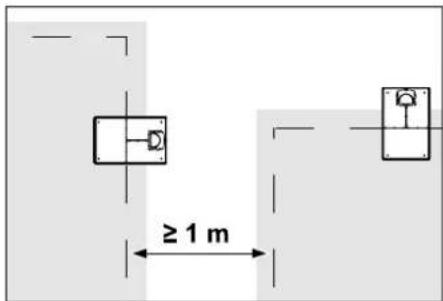
Mowing areas must not overlap. Maintain a minimum clearance of ≥ 1 m between the perimeter wires of two mowing areas.
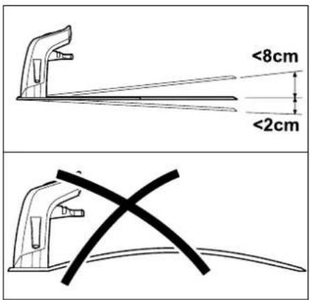
The docking station must not be inclined by more than 8 cm rearwards or 2 cm forwards. Never bend the floor plate. Any unevenness must be removed under the floor plate so that it fully contacts the ground.
Installation options:
The docking station can be installed internally and externally.
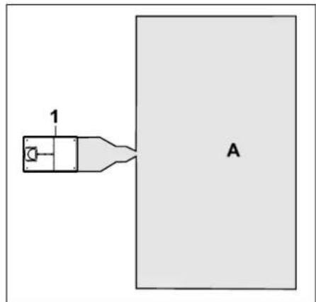
Internal docking station:
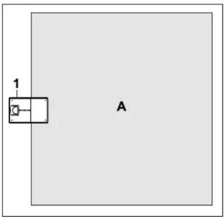
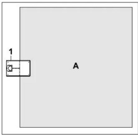
The docking station (1) is installed within the mowing area (A), right at the edge.
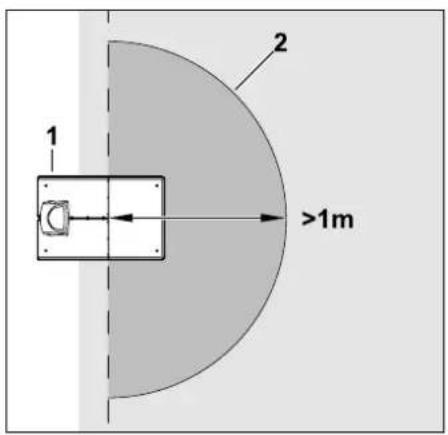
There must be a free, level area (2) with a radius of at least 1 m in front of the docking station (1). Remove any bumps or depressions.
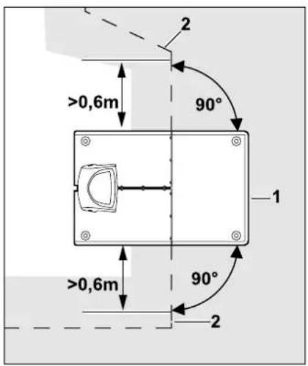
Route the perimeter wire (2) in front of and behind the docking station (1) for 0.6 m in a straight line and at right angles to the floor plate. Then follow the edge of the mowing area with the perimeter wire.
External docking station:
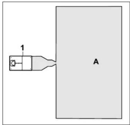
The docking station (1) is installed outside the mowing area (A).

In conjunction with an external docking station, guide loops must be installed for offset drive home. ( 12.12)
Space requirement for external docking station:
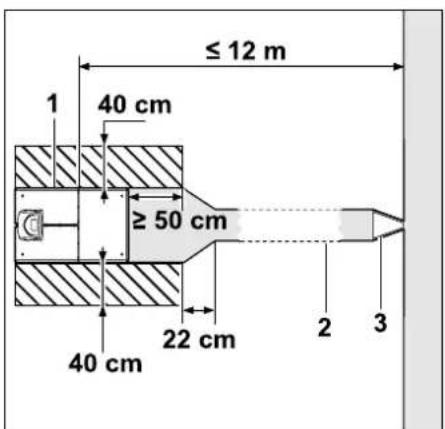
The docking station (1) can be installed as illustrated with a corridor (2) for docking and undocking to take place correctly. The areas around the docking station and outside of the perimeter wire must be flat and freely travelable. Remove any bumps or depressions.
The corridor (2) is installed using the corridor template (3). ( 12.11)
Minimum clearance from the floor plate to the start of the corridor: ≥ 50 cm
Width of the free area to the side: 40 cm
Maximum clearance to the mowing area:
≤ 12 m
Installing the docking station on a wall:
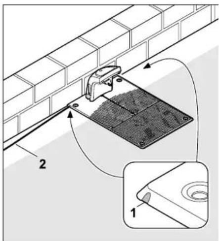
If the docking station is installed on a wall, a recess (1) must be made on the left or right of the floor plate using a pliers to make space for the power cable (2).
9.2 Docking station connections
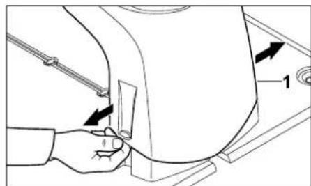
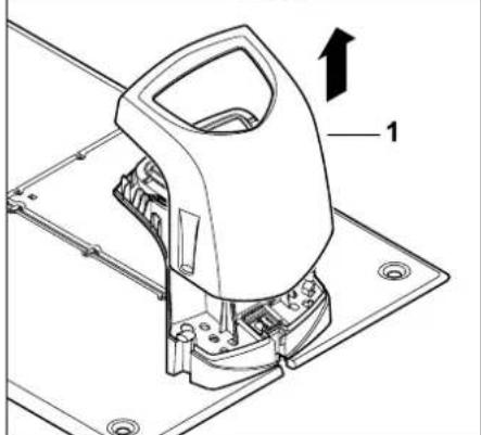
Removing the cover:
natural_image
Line drawing of a hand operating a mechanical device with arrows indicating motion (no text or symbols)
natural_image
Technical line drawing of a mechanical device with labeled component '1' and an upward arrow (no text or symbols beyond label)
Pull the cover (1) apart slightly on the left and right as illustrated and remove upwards.
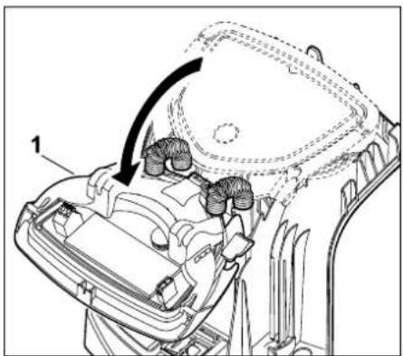
Opening the panel:
natural_image
Technical diagram of a car interior showing dashboard and steering wheel (no text or symbols)
Fold the panel (1) forwards. Hold the panel in the opened position as the hinge springs will close it automatically.
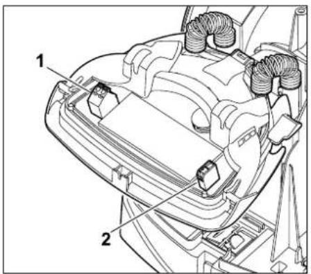
The connections for the perimeter wire (1) and the power cable (2) are protected against the weather when the panel is closed.
Closing the panel:
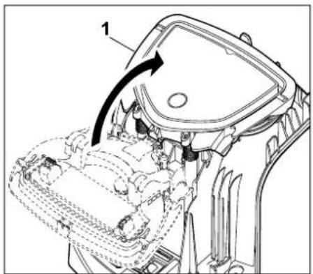
Fold the panel (1) rearwards – do not pinch any cables.
Fitting the cover:
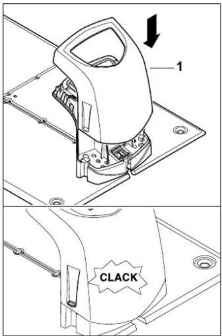
Fit the cover (1) onto the docking station and allow it to engage – do not pinch any cables.
9.3 Connecting the power cable to the docking station

Note:
The plug and connection socket must be clean.
- Remove the docking station cover and open the panel. ( 9.2)
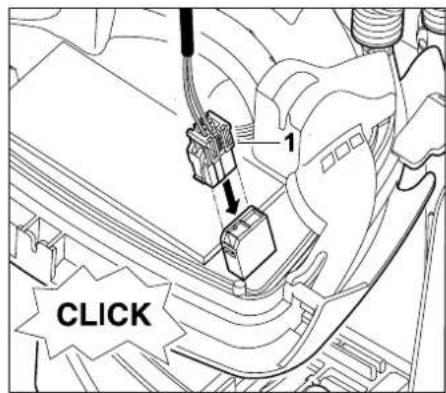
Connect the connector of the power supply unit (1) to the circuit board of the docking station.
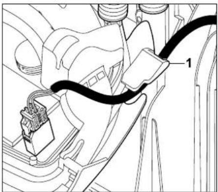
natural_image
Technical line drawing of a mechanical assembly with labeled component '1' (no text or symbols beyond label)
Guide the power cable through the cable guide (1) on the panel.
- Close the panel. ( 9.2)
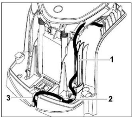
Press the power cable into the cable guide (1) as illustrated and guide through the strain relief (2) and the cable duct (3) to the power supply unit.
- Close the docking station cover. (⇒ 9.2)
9.4 Installation material
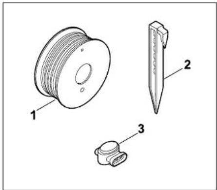
If the perimeter wire is not routed by the specialist dealer, additional installation material not included in the standard equipment will be required to be able to operate the robotic mower. ( 18.)
natural_image
Technical line drawing of three mechanical components: a spool, a pin-like tool, and a connector (no text or symbols present)
The installation kits contain perimeter wire on a reel (1) as well as fixing pins (2) and wire connectors (3). The standard equipment in the installation kits may include additional parts not required for the installation.
9.5 Adjusting the cutting height

Set the cutting height to at least level 4 in the first weeks (until the grass has grown over the perimeter wire) to prevent the perimeter wire being damaged and to guarantee reliable operation.
Levels 1, 2 and 3 are special heights for very level lawns (ground unevenness < +/- 1 cm).
Lowest cutting height: Level 1 (20 mm)
Highest cutting height:
Level 8 (60 mm)
- Open the flap. ( 15.2)
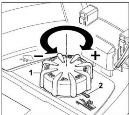
Turn the rotary knob (1). The marking (2) indicates the set cutting height.

The rotary knob can be removed upwards from the adjustment element. This design serves a safety function (it ensures that the machine cannot be lifted and carried by the rotary knob) and to prevent the cutting height from being modified by unauthorised persons.
9.6 Notes on initial installation
An installation assistant is available for installation of the robotic mower. This program guides you through the entire initial installation process:

The installation assistant must be worked through in its entirety. Only then is the robotic mower ready for operation.
The installation assistant is re-activated following a reset (reset to factory defaults). (⇒ 11.17)
Preparatory measures:
- Mow the lawn using a conventional lawn mower prior to initial installation (ideal grass height 6 cm or less).
- In the case of a hard and dry surface, water the mowing area lightly in order to make it easier to drive in the fixing pins.
- RMI 422 PC:
The robotic mower must be activated by a STIHL specialist dealer and assigned to the owner's e-mail address. (⇒ 10.)
When navigating through the menus, follow the instructions in the "Operating instructions" section. ( 11.1)
You can select options, menu items and buttons using the control pad.
You can open submenus and confirm selections using the OK button.

Use the Back button to leave the active menu or jump one step back in the installation assistant.

If errors or faults occur during the initial installation, a corresponding message appears on the display. ( 24.)
9.7 Setting the language, date and time
- Pressing any button on the display activates the machine and thus the installation assistant.

Select the required display language and confirm with the OK button.

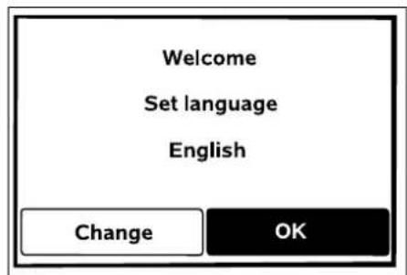

Confirm your language selection with the OK button or select "Change" and repeat the language selection.
- If necessary, enter the 9-digit serial number of the robotic mower. This number is printed on the identification plate (see Machine overview). (⇒ 3.1)
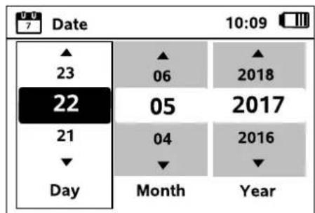
Set the current date using the control pad and confirm with the OK button.

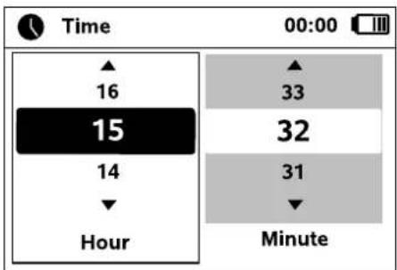
Set the current time using the control pad and confirm with the OK button.

9.8 Installing the docking station
Read the "Notes on the docking station" section ( 9.1) and study the installation examples ( 27.) in this instruction manual.
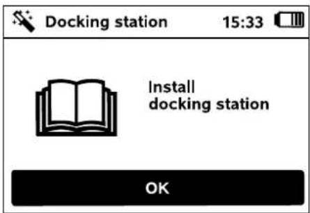
- Connect the power cable to the docking station. (⇔ 9.3)
- Route the power cable under the floor plate when the docking station is installed at a wall. ( 9.1)
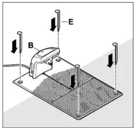
Fix the docking station (B) into position at the chosen location using four pegs (E).
- Install the power supply unit outside the mowing area, protected from direct sunlight, humidity and moisture – fasten to a wall if necessary.
Correct operation of the power supply unit is only ensured at an ambient temperature between 0^ C and 50^ C.
- Route all power cables outside the mowing area, in particular out of reach of the mowing blade, and fasten them to the ground or accommodate in a cable duct.
- Unreel power cables in the vicinity of the docking station in order to avoid interference with the wire signal.
- Connect the mains plug.
The red LED on the docking station flashes rapidly as long as no perimeter wire is connected.
(⇒ 13.1)
- After completing this installation work, press the OK button.

With external docking station:
Define at least one starting point outside the corridor to the docking station after initial installation is complete. Define the starting frequency so that 0 of 10 mowing operations (0/10) are started at the docking station (starting point 0). ( 11.15)
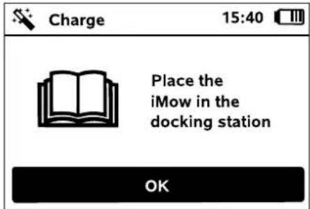
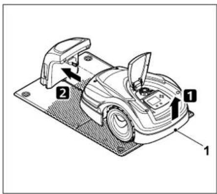
Lift the robotic mower slightly by the carrying handle (1) to relieve the weight on the drive wheels. Push the machine, resting on its front wheels, into the docking station.
Then press the OK button on the display.

If the battery is discharged, a plug symbol appears instead of the battery symbol at the top right corner of the display after docking and the battery is charged while the perimeter wire is being routed. (⇔ 15.7)
9.9 Routing the perimeter wire
Please read and observe the entire "Perimeter wire" section before performing wire routing. (⇔ 12.)
In particular, plan the routing, observe the wire clearances and install no-go areas, reserve wire, linking sections, secondary areas and corridors during wire routing.
For mowing areas < 100 m² or a wire length < 175 m, the accessory AKM 100 must be installed together with the perimeter wire.
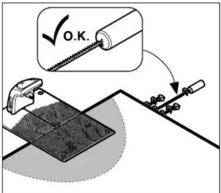
Only use genuine fixing pins and genuine perimeter wire. Installation kits with the necessary installation material are available as an accessory from the STIHL specialist dealer. (⇒ 18.)
Draw the wire routing in the garden sketch.
Content of the sketch:
- Contour of the mowing area including important obstacles, borders and any no-go areas which the robotic mower must not mow. ( 27.)
- Position of the docking station ( 9.1)
- Position of the perimeter wire
After a short while, the perimeter wire is overgrown and is no longer visible.
Make a note of the routing of the wire around obstacles in particular.
- Position of the wire connectors
After a short while, the wire connectors used are no longer visible. Their position should be noted in order to replace them as required. ( 12.16)
The perimeter wire must be routed in a continuous loop around the entire mowing area.
Maximum length: 500 m
The robotic mower must not be more than 17 m from the perimeter wire at any point, as this would prevent the wire signal being picked up.
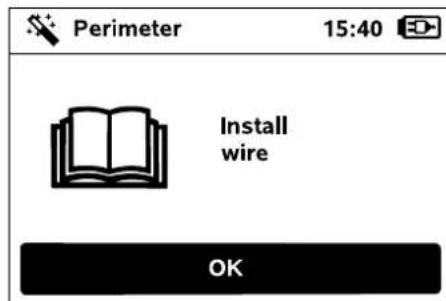
Route the perimeter wire starting at the docking station. A distinction must be made between an internal docking station and an external docking station here.
Starting routing with an internal docking station:
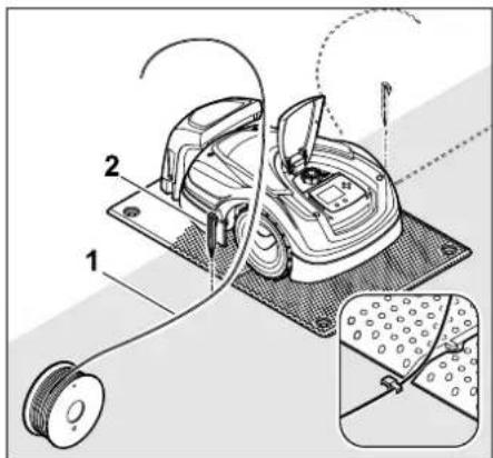
Fasten the perimeter wire (1) to the ground on the left or right as appropriate, next to the floor plate, directly next to a wire outlet, using a fixing pin (2).
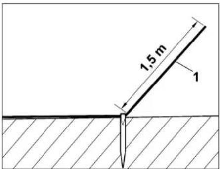
Provide a free wire end (1) with a length of approx. 1.5 m.
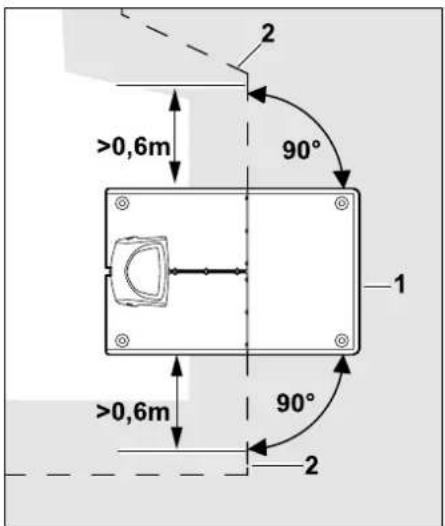
Route the perimeter wire (2) in front of and behind the docking station (1) for 0.6 m in a straight line and at right angles to the floor plate. Then follow the edge of the mowing area with the perimeter wire.
If offset drive home (passage) is used, the perimeter wire must be routed at least 1.5 m in front of and behind the docking station in a straight line and at right angles to the floor plate. ( 11.14)
Starting routing with an external docking station:
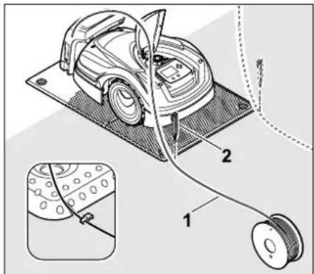
Fasten the perimeter wire (1) to the ground on the left or right as appropriate, behind the floor plate, directly next to a wire outlet, using a fixing pin (2).
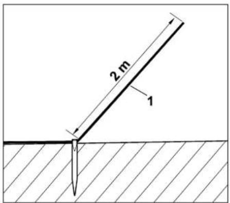
Provide a free wire end (1) with a length of approx. 2 m.
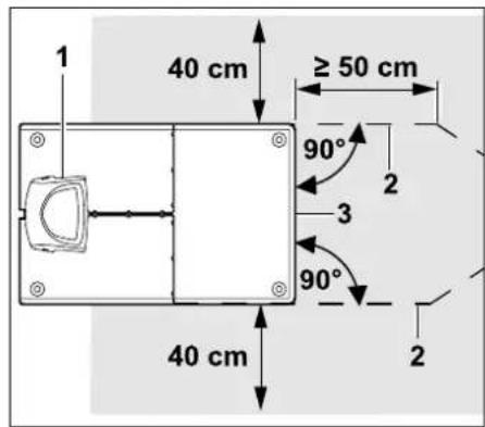
Route the perimeter wire (2) in front of and behind the docking station (1) with 50 cm of clearance and at right angles to the floor plate. A corridor can then be installed ( 12.11) or the edge of the mowing area followed with the perimeter wire.
A freely travelable area with a minimum width of 40 cm must be available to the side of the floor plate (3).
Further information on installation of the external docking station is contained in the "Installation examples" section. ( 27.)
Wire routing in the mowing area:
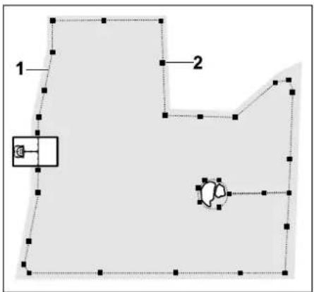
Route the perimeter wire (1) around the mowing area and around any obstacles ( 12.9) and fasten it to the ground using fixing pins (2). Check the clearances using the iMow Ruler. ( 12.5)
The robotic mower must not be more than 17 m from the perimeter wire at any point, as this would prevent the wire signal being picked up.
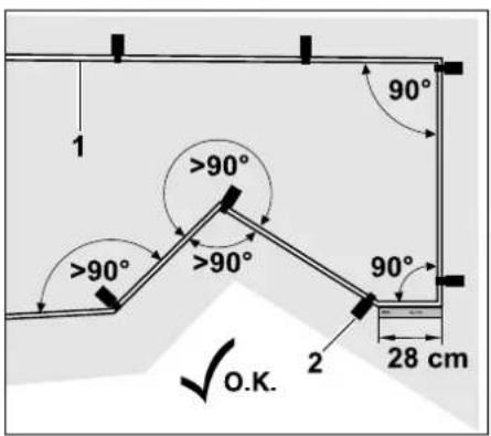
Avoid routing at acute angles (less than 90°). In acutely angled lawn corners, fasten the perimeter wire (1) to the ground with fixing pins (2) as illustrated.(⇒ 12.6)
After a 90° corner, at least the length of an iMow Ruler must be routed in a straight line before the next corner is installed.
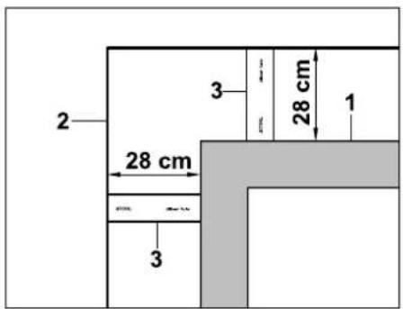
When routing around high obstacles such as wall corners or high flowerbeds (1), the wire clearance must be maintained at the corners to prevent the robotic mower from scraping against the obstacle. Route the perimeter wire (2) with the aid of the iMow Ruler (3) as illustrated.
- If necessary, extend the perimeter wire using the wire connectors supplied. (⇒ 12.16)
- In the case of several adjacent mowing areas, install secondary areas ( 12.10) or join the mowing areas with corridors. ( 12.11)
Last fixing pin with internal docking station:
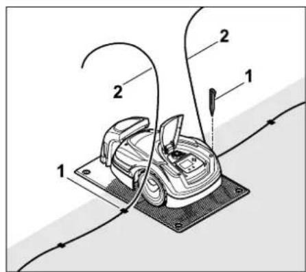
Drive in the last fixing pin (1) on the left or right next to the floor plate, directly next to the wire outlet. Cut off the perimeter wire (2) to a free length of approx. 1.5 m.
Last fixing pin with external docking station:
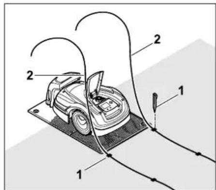
Drive in the last fixing pin (1) on the left or right behind the floor plate, directly next to the wire outlet. Cut off the perimeter wire (2) to a free length of approx. 2 m.
Completing wire routing:
- Check the fastening of the perimeter wire to the ground. One fixing pin per metre is sufficient as a rough guide. The perimeter wire must always lie on the lawn. Drive the fixing pins fully into the ground.
• After completing this installation work, press the OK button.
If the battery is not sufficiently charged to work through the remaining steps of the installation assistant, an appropriate message is displayed. In this case, leave the robotic mower in the master docking station and continue charging the battery. Jumping to the next step of the installation assistant with the OK button is only possible once the necessary battery voltage is available.
9.10 Connecting the perimeter wire
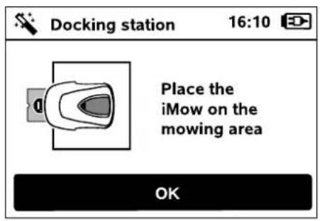
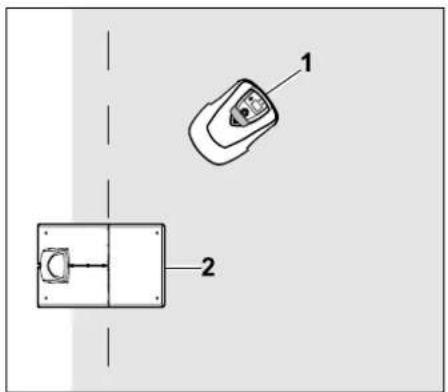
Place the robotic mower (1) within the mowing area, behind the docking station (2) as illustrated, then press the OK button.

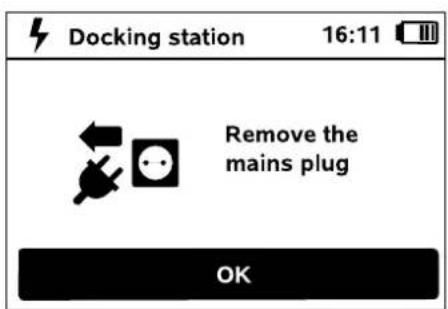
Disconnect the power supply unit plug from the mains, then press the OK button.

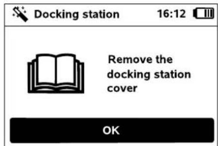
Remove the cover. ( 9.2)
Press the OK button.

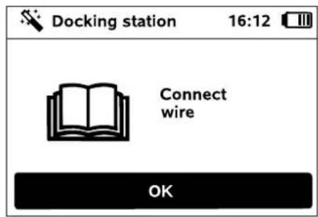
Perimeter wire with internal docking station:
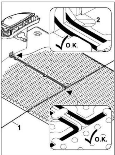
Insert the perimeter wire (1) into the cable guides in the floor plate and guide it through the socket (2).
Perimeter wire with external docking station:
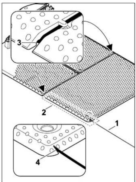
Route the perimeter wire (1) in the area (2) under the floor plate. To do this, guide the wire into the wire outlets (3, 4) – loosen the pegs if necessary.
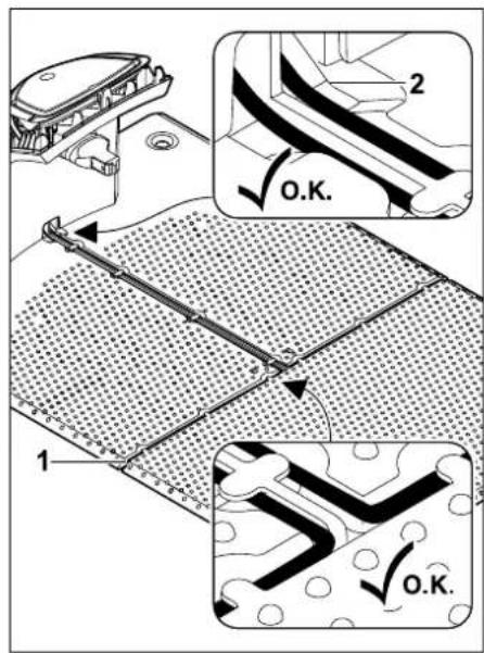
Insert the perimeter wire (1) into the cable guides in the floor plate and guide it through the socket (2).
Connecting the perimeter wire:

Note:
Make sure that the contacts are clean (not corroded, dirty, etc).
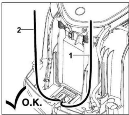
Shorten the left wire end (1) and right wire end (2) to the same length. Length from the wire outlet to the wire end: 40 cm
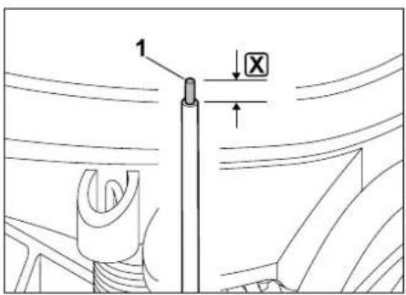
Strip the left wire end (1) to the specified length ☒ using a suitable tool and twist the wire strands.
☒ = 10-12 mm
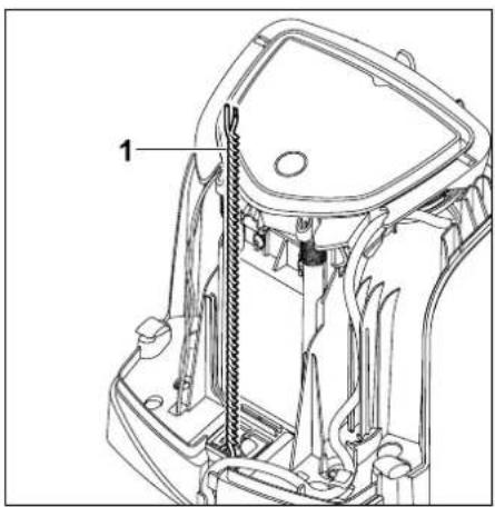
Twist the free wire ends (1) together as illustrated.
- Open the panel and hold. (⇒ 9.2)
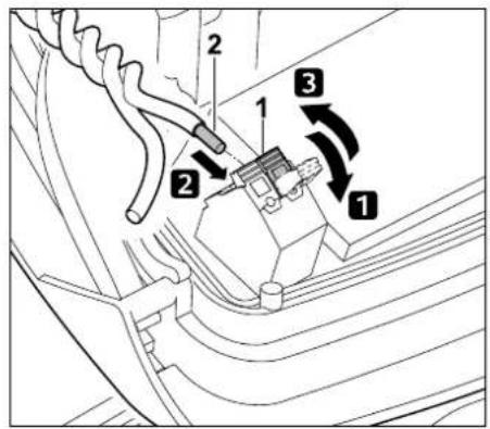
1 Fold open the left clamping lever (1).
2 Insert the stripped wire end (2) into the terminal block as far as it will go.
3 Close the clamping lever (1).
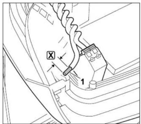
Strip the right wire end (1) to the specified length ☒ using a suitable tool and twist the wire strands.
☒ = 10-12 mm
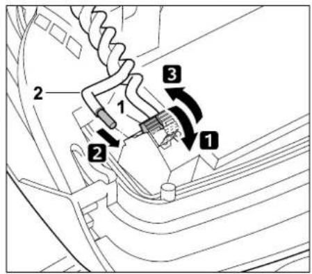
1 Fold open the right clamping lever (1).
2 Insert the stripped wire end (2) into the terminal block as far as it will go.
3 Close the clamping lever (1).
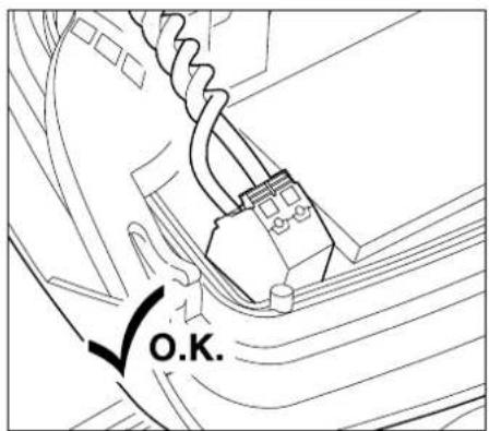
Check the seating of the wire ends in the terminal block: the two wire ends must be firmly fastened.
- Close the panel. (⇔ 9.2)
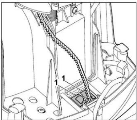
natural_image
Technical line drawing of a mechanical assembly with labeled components (no readable text or symbols)
Close the cover of the cable duct (1).
• After completing this installation work, press the OK button.

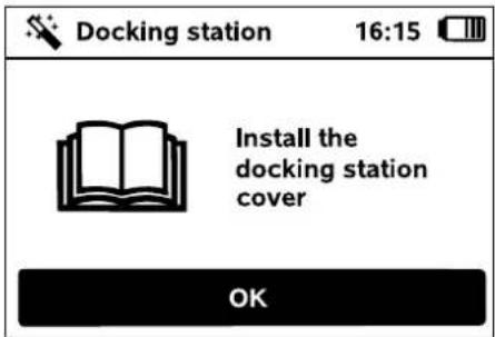
Install the cover. ( 9.2)
Press the OK button.

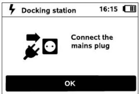
Connect the power supply unit plug to the mains, then press the OK button.


natural_image
Diagram of a cell with a labeled arrow pointing to a nucleus (no text or symbols present)
When the perimeter wire is correctly installed and the docking station is connected to the mains power supply, the LED (1) illuminates.

Observe the "Docking station controls" section, particularly if the LED does not illuminate as described. ( 13.1)
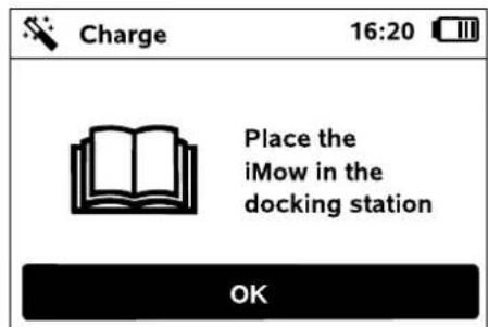
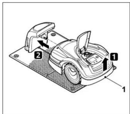
Lift the robotic mower slightly by the carrying handle (1) to relieve the weight on the drive wheels. Push the machine, resting on its front wheels, into the docking station.
Then press the OK button on the display.

9.11 Linking the robotic mower and docking station

The robotic mower can only be operated if it correctly receives the wire signal emitted by the docking station. ( 11.16)
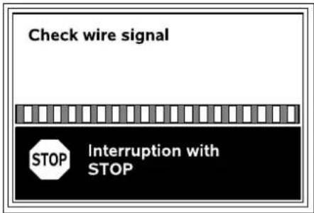
Checking the wire signal may take several minutes. The red STOP button on top of the machine terminates the link, the previous installation assistant step is called up.
Normal reception
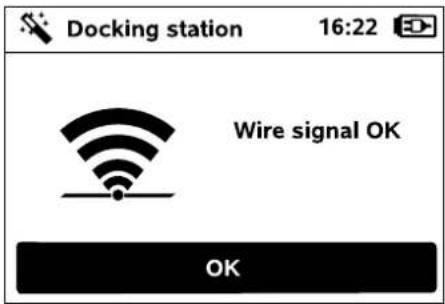
Wire signal OK:
The text "Wire signal OK" appears on the display. The robotic mower and the docking station are correctly linked.
Continue initial installation by pressing the OK button.


RMI 422 PC:
"Standard" energy mode is activated following successful linking. ( 11.11)
Interrupted reception
The robotic mower receives no wire signal:
The text "No wire signal" appears on the display.
The robotic mower receives a faulty wire signal:
The text "Check wire signal" appears on the display.
The robotic mower receives a reversed-polarity wire signal:
The text "Connections swapped or iMow outside" appears on the display.


Possible cause:
- Temporary malfunction
- Robotic mower is not docked
- Perimeter wire has been connected incorrectly (reversed polarity)
- Docking station is switched off or not connected to mains supply
– Faulty plug connections
– Minimum perimeter wire length not reached
– A coiled power cable in the vicinity of the docking station
- Perimeter wire ends excessively long or not sufficiently twisted together
- Perimeter wire break
– Extraneous signals such as a mobile phone or the signal from another docking station
– Live underground cables, reinforced concrete or disruptive metals in the ground under the docking station
- Maximum length of the perimeter wire exceeded ( 12.1)
Remedy:
- Repeat linking without other corrective action
- Dock the robotic mower (⇒ 15.6)
- Connect the perimeter wire ends correctly ( 9.10)
- Check the docking station mains connection, roll out the power cable in the vicinity of the docking station, do not set down coiled
- Check the seating of the wire ends in the terminal block, shorten excessively long wire ends and twist the wire ends together ( 9.10)
- For mowing areas < 100 ~m^2 or a wire length < 175 ~m , the accessory AKM 100 must be installed together with the perimeter wire. (9.9)
- Check the LED indicator on the docking station ( 13.1)
- Repair the wire break
– Switch off mobile phones or nearby docking stations
- Change the position of the docking station or remove interference sources under the docking station
- Use a perimeter wire with larger cross section (special accessory)
Following the appropriate corrective action, repeat linkage by pressing the OK button.


Contact your specialist dealer if the measures described above do not result in a correct wire signal.
9.12 Checking the installation
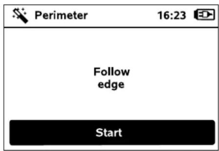
Start edge following by pressing the OK button – this does not activate the mowing blade.

The robotic mower alternately follows the edge of the mowing area in both directions during running operation after initial installation. Edge following should therefore also be checked in both directions during initial installation.
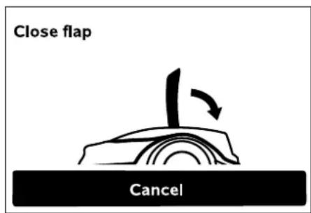
Close the flap of the robotic mower. ( 15.2) Only once the flap has been closed does the robotic mower start automatically and follow the edge along the perimeter wire.

RMI 422 PC:
Edge following is used to define the home area of the robotic mower.
(⇒ 14.5)
If the robotic mower is not receiving a GPS signal before starting edge following, the text "Waiting for GPS" appears on the display. The robotic mower starts edge following after a few minutes despite no GPS signal being received. The "Test edge" function ( 11.14) must be performed later in order to use GPS protection, as otherwise no home area is defined.
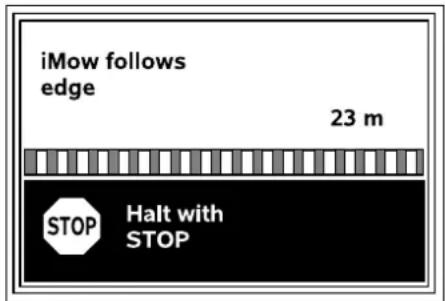
As the robotic mower follows the edge, walk behind it and ensure
– that the robotic mower follows the edge of the mowing area as planned,
– that the clearances to obstacles and the borders of the mowing area are correct,
– that docking in and out takes place correctly.
The distance covered is shown on the display – this metric specification is required for setting starting points at the edge of the mowing area. ( 11.14)
- Read off the displayed value at the required location and write it down. Manually set starting points after initial installation.
The following of edges is automatically interrupted by obstacles, during operation on excessively steep slopes or by pressing the STOP button.
- If edge following has been interrupted automatically, correct the position of the perimeter wire and remove any obstacles.
- Check the position of the robotic mower before continuing edge following. The machine must either be located on the perimeter wire or within the mowing area with the front facing the perimeter wire.
Continuation following interruption:
After an interruption, continue edge following with OK.

It is recommended by STIHL not to interrupt edge following. Possible problems when following the edge of the mowing area or when docking may not be recognised.
Edge following can be repeated following initial installation if necessary. ( 11.14)
The robotic mower docks after one complete circuit around the mowing area. The system then queries as to whether a second edge following run in the opposite direction should be started.
Automatic completion of edge following:
The next step of the installation assistant is called up when the robotic mower docks following the second complete circuit or if edge following in the opposite direction is refused.
9.13 Programming the robotic mower
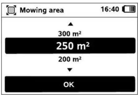
Enter the size of the lawn and confirm with OK.

Installed no-go areas and secondary areas must not be included when calculating the size of the mowing area.
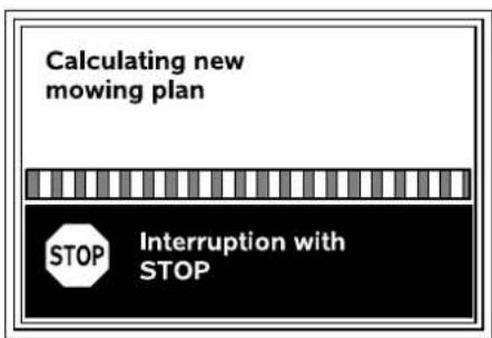
A new mowing plan is calculated. The procedure can be aborted using the red STOP button on the top of the machine.
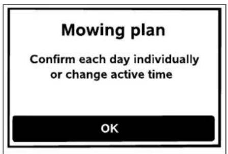
Confirm the message "Confirm each day individually or change active time" by pressing the OK button.

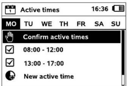
The active times for Monday are displayed and the menu item Confirm active times is enabled.
All the active times are confirmed with OK and the next day is displayed.


In the case of small mowing areas, not all the week days are used for mowing. In this case, no active times are displayed and the menu item "Delete all active times" is omitted. Days without active times must also be confirmed with OK.
The displayed active times can be changed. For this purpose, select the required time interval using the control pad and open with OK. ( 1

If additional active times are required, select the menu item

New active time and open with OK.
Specify the start and end times of the new active time in the selection window and confirm with OK. Up to three active times per day are possible.
If all the displayed active times are to be deleted, select the menu item Delete all active times and confirm with OK.

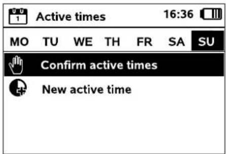
The mowing plan is displayed after the active times for Sunday have been confirmed.

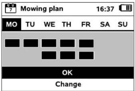
The displayed mowing plan is confirmed with OK and the final step of the installation assistant is called up.

If changes are necessary, select Change and individually adapt active times.

During the active times, third parties must keep out of the danger area. The active times should be adapted accordingly.
Moreover, the applicable local regulations on the use of robotic mowers as well as the information in the "For your safety" ( 6.) section must be observed and the active times changed accordingly in the "Mowing plan" menu as required, either immediately or after completion of initial installation.
( 11.6)
In particular, you should check the times of the day and night at which it is permissible to use the machine with the responsible authorities.
9.14 Completing initial installation

Remove all foreign bodies (e.g. toys, tools) from the mowing area.
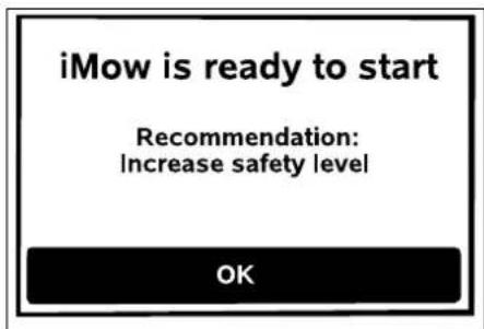
Complete initial installation by pressing the OK button.


After initial installation, the safety level "None" is activated.
Recommendation:
Set the safety level to "Low", "Medium" or "High". This ensures that unauthorised persons cannot change any settings or operate the robotic mower using other docking stations. ( 11.16)
RMI 422 PC:
In addition, activate GPS protection. ( 5.9)
RMI 422 PC:
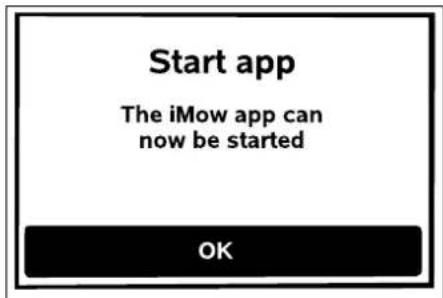
To be able to use all the functions of the robotic mower, the iMow app must be installed on a smartphone or tablet with an Internet connection and GPS receiver, and started. (⇔ 10.)
Close the dialog window by pressing the OK button.

9.15 First mowing operation after initial installation
If completion of initial installation occurs during an active time, the robotic mower will begin to mow the mowing area immediately.
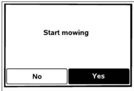
If completion of the initial installation occurs outside the active time, a mowing operation can be started by pressing the OK button. If you do not wish the robotic mower to mow, select "No".
10. iMow app
The model RMI 422 PC can be operated using the iMow app.
The app is available for the most popular operating systems in respective app stores.
Further information is available on the web.imow.stihl.com/systems/homepage.
The regulations in the "For your safety" section apply in particular to all users of the iMow app. ( 6.)
Activation:
In order for the app and robotic mower to be able to exchange data, the machine must be activated with the owner's e-mail address by the specialist dealer. An activation link is sent to the e-mail address. The iMow app should be installed on a smartphone or tablet with an Internet connection and GPS receiver. The e-mail recipient is defined as the administrator and primary user; this person has full access to all functions.
Keep the e-mail address and password safe so that the iMow app can be reinstalled should the smartphone or tablet be changed (e.g. if the mobile phone is lost).
Data traffic:
Data transmission from the robotic mower to the Internet (M2M service) is included in the purchase price.
Data transmission does not take place continuously and can therefore take a few minutes.
The transmission of data from the app to the Internet will result in costs that must be borne by the user; these costs will be determined by the contract with the mobile phone provider or Internet provider.
GPS protection is only available without e-mail, SMS and push notifications without a mobile radio connection and app.
Main functions of the app:
– Viewing and editing the mowing plan
- Starting mowing
– Switching automatic mowing on and off
- Sending the robotic mower to the docking station
- Changing the date and time

Changing the mowing plan, starting a mowing operation, switching automatic mowing on and off, sending the robotic mower home and changing the date and time can result in activities that will not be expected by other people. Affected people must therefore always be notified in advance about possible activities of the robotic mower.
- Calling up machine information and the location of the robotic mower
11.1 Operating instructions
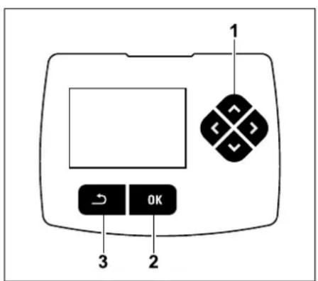
The control pad comprises four direction buttons (1). It serves for navigation in the menus. Settings are confirmed and menus
opened using the OK button (2). Menus can be exited again using the Back button (3).
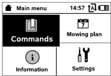
The main menu comprises 4 submenus, displayed as buttons. The selected submenu has a black background and is opened using the OK button.
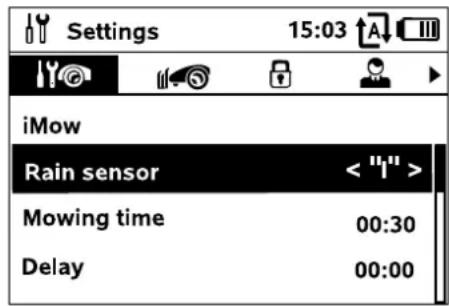
In the second menu level, the various submenus are shown as tabs.
The tabs can be selected by pressing the control pad to the left or right, submenus by pressing the control pad downwards or upwards.
Active tabs and menu entries have a black background.
The scroll bar at the right edge of the display indicates that further entries can be displayed by pressing the control pad downwards or upwards.
Submenus are opened by pressing the OK button.
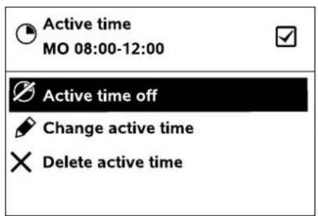
Options are listed in the submenus. Active list entries have a black background. Pressing the OK button opens a selection or a dialog window.
Selection window:
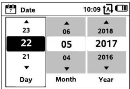
Settings can be changed by pressing the control pad. The current value is highlighted in black. The OK button confirms all the values.
Dialog window:
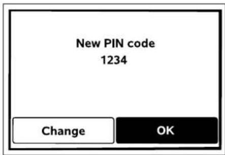
If changes have to be saved or messages confirmed, a dialog window appears on the display. The active button has a black background.
In the case of selection options, the relevant button can be activated by pressing the control pad to the left or right. The selected option is confirmed and the subordinate menu called up using the OK button.
11.2 Status screen
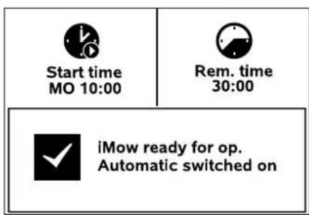
The status screen appears:
- when standby mode of the robotic mower is ended by pressing a button,
- when the Back button is pressed in the main menu,
– during running operation.
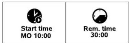
There are two configurable fields in the top display area. Various information regarding the robotic mower and the mowing operations can be displayed here.
(⇒ 11.13)
Status information with no running activity – RMI 422, RMI 422 P:
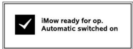
The text "iMow ready for op." is displayed in the bottom area of the screen together with the symbol shown and the automatic mowing status. (⇒ 11.5)
Status information with no running activity – RMI 422 PC:
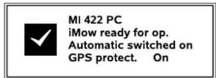
The name of the robotic mower ( 10.), the text "iMow ready for op." is displayed in the bottom area of the

screen together with the symbol shown, the automatic mowing status ( 11.5) and information on GPS protection ( 5.9).
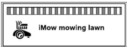
The text "iMow mowing lawn" and a corresponding symbol are shown on the display during a running mowing operation. The text and sy are adapted to the respective active operation.

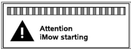
The text "Attention – iMow starting" and a warning symbol are displayed before the mowing operation.

Flashing of the display illumination and a signal tone additionally indicate the impending start of the mowing motor. The mowing blade is only activated a few seconds after the robotic mower has been set into motion.
Edge mowing:
While the robotic mower mows the edges of the mowing area, the text "Mowing edge" is displayed.

Drive to docking station:
When the robotic mower returns to the docking station, the relevant reason is indicated in the display (e.g. Battery discharged, Mowing completed).
Battery charging:
The text "Charging battery" appears during charging of the battery.

Message screen – all models:
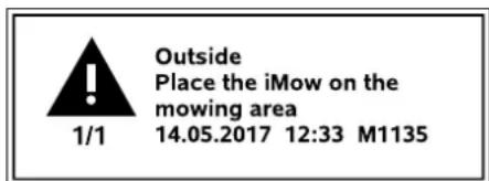
Errors, faults or recommendations are displayed together with warning symbol, date, time and message code. If several messages are active, they appear alternately. ( 24.)

The message and status information appear alternately if the robotic mower is ready for operation.
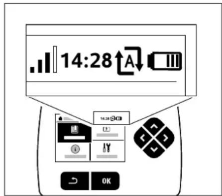
The following information is shown in the top right corner of the display:
- Charge state of the battery or charging in progress
- Automatic mowing status
- Time
- Mobile radio signal (RMI 422 PC)
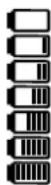
1. Charge state:
The battery symbol serves to indicate the charge state.
No bars – battery discharged
1 to 5 bars – battery partially
discharged
6 bars – battery fully charged
During charging, the mains plug symbol is shown instead of the battery symbol.
2. Automatic mowing status:
When automatic mowing is switched on, the Automatic symbol appears.


3. Time:
The current time is indicated in 24 hour format.
4. Mobile radio signal:
The signal strength of the mobile radio connection is indicated using 4 bars. The more bars visible, the better the reception.
A reception symbol with a small x indicates that there is no connection with the Internet.
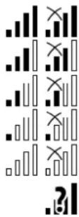
A question mark is shown during initialisation of the radio module (checking hardware and software – e.g. after switching on the robotic mower).
11.4 Main menu
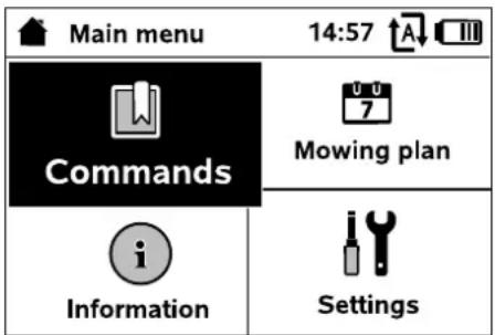
The main menu is displayed,

Main menu
Lock iMow
Switch automatic mowing on and off
Drive to docking station
Start mowing
Start time-delayed mowing
Skip next active time
Edge mowing
- Mowing plan ( 11.6)
Display weekly plan, edit active
times and mowing duration
- Information ( 11.9)
Messages
Events
iMow status
Lawn status
Radio module status (RMI 422 PC)
- Settings ( 11.10)
iMow
Installation
Safety
Service
Dealer area
11.5 Commands
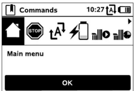
Select the required command using the control pad and execute by pressing OK.
- Main menu


- Lock iMow
- Switch on automatic mowing/Switch off automatic mowing
- Drive to docking station
- Start mowing
- Start time-delayed mowing
- Skip next active time
- Edge mowing
1. Main menu:
OK takes you back to the main menu.
2. Lock iMow:
Activates the disabling device.
Press the illustrated button combination to unlock. ( 5.2)
3. Switch on automatic mowing/
Switch off automatic mowing: When automatic mowing is
switched on, the text "Automatic switched on" appears in the status screen and the automatic symbol is displayed next to the battery symbol in the menus. The robotic mower mows the mowing area fully automatically.
When automatic mowing is switched off, the text "Automatic switched off" appears in the status screen and the active times are shown as inactive (greyed out) in the mowing plan. The mowing area is not mown automatically. Mowing operations can be initiated via the commands "Start mowing" or "Start time-delayed mowing".

RMI 422 PC:
Automatic mowing can also be switched on and off using the app. The robotic mower returns to the docking station when automatic mowing is switched off using the app. ( 10.)
4. Drive to docking station:
The robotic mower travels back to the docking station and charges the battery. If automatic mowing is switched on, the robotic mower will mow the mowing area again at the next possible active time.

RMI 422 PC:
The robotic mower can also be sent to the docking station using the app. ( 10.)
5. Start mowing:
The robotic mower starts the mowing operation automatically following activation. The end of the mowing operation must be specified. If a secondary area was installed, after pressing the OK button it is necessary to define whether mowing is taking place on a secondary area or on the main area. (⇒ 11.14)
The standard setting for the duration of the mowing operation can be modified under "Mowing time" in the machine settings. (⇒ 11.8)

If an external docking station with a corridor was installed, bring the robotic mower to the mowing area before activation of the command "Start mowing".
RMI 422 PC:
"Start mowing" can also be activated in the app. ( 10.)
6. Start time-delayed mowing:
The robotic mower starts the mowing operation automatically, but with a time delay, following activation. The start and end times of the mowing operation must be specified. If a secondary area was installed, after pressing the OK button it is necessary to define whether mowing is taking place on a secondary area or on the main area. (⇒ 11.14)
The standard settings for the duration of the mowing operation and for the delay can be changed in the machine settings under "Mowing time" and "Delay". (⇒ 11.8)

If an external docking station with a corridor was installed, bring the robotic mower to the mowing area before activation of the command "Start time-delayed mowing".
RMI 422 PC:
"Start time-delayed mowing" can also be activated in the app. ( 10.)
7. Skip next active time:
This command can be used if the robotic mower is not to be operated during the next active time (e.g. in the case of a garden party). Following confirmation, no mowing will take place during the next active time. Active times which have been cancelled in this manner are greyed out in the mowing plan. They can be released for mowing again in the "Daily plan" menu. (⇒ 11.7) If the command is performed several times in succession, the next active time is always skipped. If no active times remain for the current week, the message "No mowing will take place next week" appears.

8. Edge mowing:
Following activation, the robotic mower mows the edge of the mowing area. After completing one circuit, it travels back to the station and charges the battery.

11.6 Mowing plan
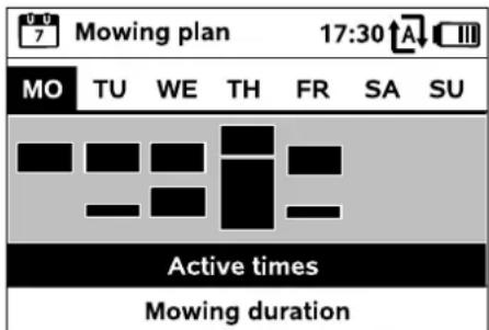
The stored mowing plan can be called up via the "Mowing plan" menu in the main menu. The rectangular blocks beneath the rest days represent the saved active time. Mowing is possible in active times in black. Grey blocks represent active times without mowing operations, the case of a disabled active time, following the command "Skip activ ( 11.5)


When automatic mowing is switched off, the entire mowing plan is disabled and all active times are shown in grey.
The Active times ( 11.7) or Mowing duration ( 11.8) submenus can be selected by pressing the control pad upwards or downwards and opened with the OK button.
If the active times for an individual day need to be edited, the day must be activated via the control pad (press to the left or right) and the Active times submenu must be opened.
11.7 Active times
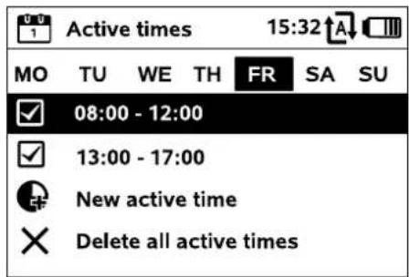
Mowing is permitted during ticked active times; these times are marked in black in the mowing plan.

Mowing is not permitted during unticked active times; these times are marked in grey in the mowing plan.


Follow the instructions in the "Active times" section. (⇒ 14.3) In particular, third parties must keep out of the danger area during the active times.

RMI 422 PC:
Active times can also be edited using the app. ( 10.)
The stored active times can be individually selected and edited.
The New active time menu item can be selected provided fewer than 3 active times per day have been saved. An additional active time must overlap with other active times.

If the robotic mower is not to mow on the selected day, the menu item Delete all active times should be selected.
Editing active times:
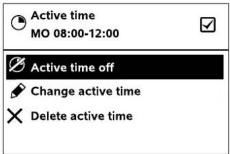
The selected active time for automatic mowing can be disabled or enabled using Active time off and Active time on respectively.
The time window can be changed with Change active time.
If the selected active time is no longer required, the menu item Delete active time should be selected.
If the time windows for the necessary mowing and charging operations are not sufficient, active times must be extended or added, or the mowing duration must be reduced. A corresponding display message appears.


11.8 Mowing duration
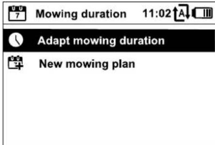

The weekly mowing time can be set under Adapt mowing duration.
The set value is adapted to the size of the mowing area. ( 14.4)
Follow the instructions in the "Adapting the programming" section. ( 15.3)

RMI 422 PC:
The mowing duration can also be set using the app. ( 10.)
The command New mowing plan deletes all stored active times. The step "Program the robotic mower" of the installation assistant is called up. ( 9.13)


If completion of the reprogramming occurs during an active time, the robotic mower begins an automatic mowing operation after the individual daily plans have been confirmed.
11.9 Information
| i | Information | 10:32A |
| | |
| Messages |
| Rain detected | FR 13:52 |
| Recommendation | SU 15:00 |
1. Messages:
List of all active errors, faults and recommendations; shown together with the times of occurrence.

During trouble-free operation, the text "No messages" appears.
The message details are displayed by pressing the OK button. ( 24.)
2. Events:
List of the last activities of the robotic mower.

Details of the events (additional text, time and code) can be displayed by pressing the OK button.

If certain activities occur too frequently, detailed information is available from your specialist dealer. Errors during normal operation are documented in the messages.
3. iMow status:
Information on the robotic mower

- Charge state:
Battery charge in percent
- Rem. time:
The remaining mowing duration during the current week in hours and minutes
- Time and date
- Start time:
Start of the next planned mowing operation
– Total number of completed mowing operations
- Mowing hours:
Duration of all completed mowing operations in hours
- Distance:
Total distance covered in metres
- Ser.-No.:
Serial number of the robotic mower. This can also be found on the identification plate (see Machine overview). ( 3.1)
- Battery:
Serial number of the battery
- Software:
Installed machine software
4. Lawn status:
Information on the lawn

- Mowing area in square metres:
This value is entered during initial installation or new installation ( 9.)
- Round time:
Duration of one circuit around the mowing area in minutes and seconds
- Starting points 1 - 4:
Distance of the relevant starting point from the docking station in metres, measured in a clockwise direction ( 11.15)
- Circumference:
Circumference of the mowing area in metres
- Edge mowing:
Frequency of edge mowing per week
(⇒ 11.14)
5. Radio module status
(RMI 422 PC):
Information on the radio module

- Satellites:
Number of satellites within range
- Position:
Current position of the robotic mower; available if the satellite connection is strong enough
– Signal strength:
Signal strength of the mobile radio connection; the more plus characters shown (max. "++++"), the better the connection
- Network:
Network ID, comprising country code (MCC) and provider code (MNC)
- Mobile phone number:
Mobile phone number of the owner; is entered in the app ( 10.)
- IM E I :
Hardware number of the radio module
- I M S I :
International mobile subscriber identity
- SW:
Software version of the radio module
- Ser. - No.:
Serial number of the radio module
11.10 Settings
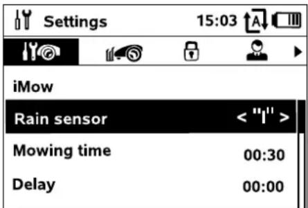
1. iMow:
Adapt machine settings ( 11.11)
2. Installation:
Adapt and test the installation
(⇒ 11.14)
3. Safety:
Adapt the safety settings (⇒ 11.16)
4. Service:
Maintenance and service (⇒ 11.17)
5. Dealer area:
This menu is protected by the dealer code. Your specialist dealer performs a variety of maintenance and service operations with the aid of this menu.
11.11 iMow - machine settings
1. Rain sensor:
The rain sensor can be set so that mowing is interrupted or does not start when it is raining.
- Setting the rain sensor (⇒ 11.12)
2. Mowing time:
Set the standard for the duration of a mowing operation after activation of the command "Start mowing". ( 11.5)
3. Delay:
Set the standard for the delay following activation of the command "Start time-delayed mowing". (⇔ 11.5)
4. Status screen:
Select the information that is to appear in the status screen.
(⇒ 11.2)
- Setting the status screen (⇒ 11.13)
5. Time:
Set the current time.
The set time must correspond to the actual time in order to prevent inadvertent mowing by the robotic mower.

RMI 422 PC:
The time can also be set using the app. ( 10.)
6. Date:
Set the current date.
The set date must correspond to the actual calendar date in order to prevent inadvertent operation of the robotic mower.

RMI 422 PC:
The date can also be set using the app. ( 10.)
Set the required date format.
8. Track offset:
The robotic mower travels along the perimeter wire at a 6 cm offset from the wire as standard. With this offset, optimum docking is ensured. The iMow Ruler is also designed for a track offset of 6 cm.


STIHL recommends that the standard setting of 6 cm is not changed.
- Only if necessary, open the selection window with OK and set the required value (3 cm to 9 cm).
9. Language:
Set the required display language. The language selected during initial installation is set as the default.
10. Contrast:
The display contrast can be adjusted as required.
11. Energy mode (RMI 422 PC):
In Standard, the robotic mower is connected to the Internet at all times and can be reached using the app, provided sufficient battery charge is available. ( 10.)
In ECO, radio communication is deactivated during rest periods to reduce energy consumption; the robotic mower cannot be reached using the app. The most recent available data is shown in the app.
11.12 Setting the rain sensor
In order to set the 5-stage sensor, press the control pad to <""|"> the left or right. The current value is displayed in the "Settings" menu by means of a line diagram.
Moving the control influences
– the sensitivity of the rain sensor,
– the time the robotic mower waits for the sensor surface to dry following rain.
In the case of medium sensitivity, the robotic mower is ready for operation under normal ambient conditions.
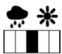
Move the bar further to the left for mowing at a higher humidity. If the bar is moved all the way to the left, the robotic mower will mow even
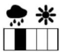
in wet external conditions and will not interrupt the mowing operation if rain drops land on the sensor.
Move the bar further to the right for mowing at a lower humidity. If the bar is moved all the way to the right, the robotic mower will only mow it
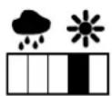
the rain sensor is completely dry.
11.13 Setting the status screen
In order to configure the status screen, select the left or right screen with the control pad and confirm with OK.
Charge state:
Shows the battery symbol with the charge state in percent

Rem. time:
The remaining mowing duration during the current week in hours and minutes

Time and date:
Current time and current date

Start time:
Start of the next planned mowing operation. During a running active time, the text "active" is displayed.

Mowing ops:
Total number of mowing operations performed

Mowing hours:
Total duration of all mowing operations performed
Distance:
Total distance covered
Network
(RMI 422 PC):
Signal strength of the mobile radio connection with network ID. A small x or question mark indicates that the robotic mower is not connected to the Internet. ( 11.3), ( 11.9)
GPS reception
(RMI 422 PC):
GPS coordinates of the robotic mower. ( 11.9)


11.14 Installation
1. Passage:
Switch offset drive home on and off. When the passage is activated, the robotic mower travels back home to the docking station, offset at a distance, along the perimeter wire.
Three versions can be selected:
Off - Default setting
The robotic mower travels along the perimeter wire.
Narrow - 40 cm
The robotic mower alternatively travels along the perimeter wire or offset by 40 cm.
Wide - 40 - 80 cm
The distance to the perimeter wire is selected randomly within this passage during each drive home.

In conjunction with an external docking station as well as with corridors and confined areas, guide loops must be installed for offset drive home. ( 12.12)
Observe a minimum wire clearance of 2 m for offset drive home.
2. ASM (anti-stuck manoeuvre):
When ASM is switched on, the robotic mower starts an evasive routine if it gets stuck.
On – ASM can be switched on to avoid getting stuck.
Off – Default setting. ASM should remain switched off
- if the mowing area contains larger level surfaces (e.g. asphalted drives),
- if the robotic mower often turns 90^ unexpectedly during the work,
- if the robotic mower remains stationary with the message 1131 without getting stuck during the work.
3. New installation:
The installation assistant is started again, the existing mowing plan is deleted. ( 9.)

4. Starting points:
The robotic mower either starts the mowing at the docking station (default setting) or at a starting point.
Starting points are to be defined
- if partial areas are to be travelled to in a targeted manner because they are insufficiently mowed,
- if areas can only be accessed via a corridor. At least one starting point must be defined in these partial areas.
RMI 422 PC:
The starting points can be assigned a radius. If the robotic mower starts mowing

at the relevant starting point, it always mows within a circle around the starting point first. Once it has mown this partial area, it continues mowing in the remaining area.
- Setting starting points ( 11.15)
5. Test edge:
Start edge following for checking correct wire routing.
The step "Check installation" of the installation assistant is called up. ( 9.12)


To check correct wire routing around no-go areas, position the robotic mower in the mowing area with the front facing the no-go area and start edge following.
The home area of the robotic mower is defined during edge following. If necessary, a home area already stored in the memory is extended. ( 14.5)
6. Edge mowing:
Define the mowing frequency.
Never – The edges are never mown.
Once – Default setting, the edges are mown once a week.
Twice – The edges are mown twice per week.

7. Secondary areas:
Enable secondary areas.
Inactive – Default setting
Active – Setting if secondary areas are to be mown. With the commands "Start mowing" and "Start time-delayed mowing", the mowing area (main area/secondary area) must be selected. ( 15.5)

11.15 Setting starting points
To set, either
- learn starting points
or
- select the required starting point and define it manually.
Teaching in starting points:
After pressing the OK button, the robotic mower begins a new learning run along the perimeter wire. If it is not docked, it first travels to the docking station. All the existing starting points are deleted.


RMI 422 PC:
The home area of the robotic mower is defined during the learning run. If necessary, a home area already stored in the memory is extended. ( 14.5)
During travel, up to 4 starting points can be specified by pressing the OK button after opening the flap.

Avoid pressing the STOP button before opening the flap as this interrupts the learning run. Interruption is generally only necessary to change the wire position or remove obstacles.
Interrupting the learning procedure:
Manually – by pressing the STOP button. Automatically – by obstacles at the edge of the mowing area.
- If the learning run has been interrupted automatically, correct the position of the perimeter wire and remove any obstacles.
- Check the position of the robotic mower before continuing the learning run. The machine must either be located on the perimeter wire or within the mowing area with the front facing the perimeter wire.
Ending the learning procedure:
Manually – following an interruption.
Automatically – after docking.
After docking or after the interruption, the new starting points are saved by confirming with OK (after opening the flap). Starting frequency:
The starting frequency defines how often a mowing operation is to begin from a starting point. The default setting is 2 of 10 mowing operations (2/10) at each starting point.
- Change the starting frequency as required after learning.
- If the learning procedure has been aborted prematurely, send the robotic mower back to the docking station via a command. ( 11.5)
• RMI 422 PC:
A radius from 3 m to 30 m around each starting point can be defined after learning. The stored starting points are not assigned any radius as standard.

Starting points with radius:
When the mowing operation is started at the respective starting point, the robotic mower starts by mowing the partial area within the circular segment around the starting point. Only then does it mow the rest of the mowing area.
Setting starting point 1 to 4 manually:
Determine the distance of the starting points from the docking station and define the starting frequency.
The distance corresponds to that covered from the docking station to the starting point in metres, measured in a clockwise direction.

The starting frequency can be between 0 of 10 mowing operations (0/10) and 10 of 10 mowing operations (10/10).
RMI 422 PC:
A Radius from 3 m to 30 m around the starting point can be defined.

The docking station is defined as starting point 0;
mowing operations are started from here as standard. The starting frequency corresponds to the calculated residual value of 10 out of 10 operations.

11.16 Safety
- Disabling device
- Level
- GPS protection (RMI 422 PC)
- Change PIN code
- Start signal
- Alarm signal
- Menu signal
- Child lock
- Keylock
10.Link iMow and dock
1. Disabling device:
The disabling device is activated with OK; the robotic mower can no longer be operated.
The robotic mower must be disabled prior to any maintenance or cleaning work, prior to transportation and prior to inspection. ( 5.2)
- To deactivate the disabling device, press the illustrated button combination.

2. Level:
Four safety levels can be set; various locks and safety devices are activated, depending on the level.
- None:
The robotic mower is unprotected.
- Low:
The anti-theft alarm is active; a PIN code must be entered in order to link the robotic mower and docking station, and to reset the machine to the default settings.
- Medium:
As "Low", but the time lock is also active.
- High:
As "Medium", but settings can also only be changed following entry of the PIN code.

STIHL recommends that one of the safety levels "Low", "Medium" or "High" be set.
- Select the required level and confirm with OK; enter the 4-digit PIN code if necessary.
Anti-theft alarm:
If the mower is lifted or tilted by the handle for longer than 10 seconds, the PIN query appears. If the PIN code is not entered within one minute, an alarm sounds and automatic operation is switched off.
Connection lock:
PIN code query prior to linking of the robotic mower and docking station.
Reset lock:
PIN code query prior to resetting the machine to the factory defaults.
Time lock:
PIN code query for changing a setting if no PIN code has been entered for more than one month.

Setting protection:
PIN code query when settings are changed.
3. GPS protection (RMI 422 PC):
For switching position monitoring on and off. ( 5.9)


Recommendation:
Always switch on GPS protection. Before switching on, enter the mobile phone number of the owner in the app ( 10.) and set the safety level to "Low", "Medium" or "High" on the robotic mower.
4. Change PIN code:
The 4-digit PIN code can be changed if required.


The "Change PIN code" menu item is only displayed in the safety levels "Low", "Medium" or "High".
- First enter the old PIN code and confirm with OK.
- Then enter the new 4-digit PIN code and confirm with OK.

STIHL recommends making a note of the changed PIN code.
If the PIN code is entered incorrectly 5 times, a 4-digit master code is required, otherwise automatic operation is switched off. For the creation of a master code, you must provide your STIHL specialist dealer with the 9-digit serial number and the 4-digit date, which are displayed in the selection window.
5. Start signal:
For switching on and off the acoustic signal that sounds when the mowing blade is activated.

6. Alarm signal:
For switching on and off the acoustic signal that sounds when the robotic mower hits an obstacle.

For switching on and off the acoustic click that sounds when a menu is opened and a selection is confirmed with OK.

8. Child lock:
If the impact sensor is triggered several times in succession within a short time, the robotic mower and the mowing blade will stop.
If the impact sensor is not triggered again, the robotic mower will continue automatic mowing after a few seconds.
9. Keylock:
When the keylock is switched on, the buttons on the display can only be operated if the Back

button is pressed and held and the control pad is then pressed forwards. The keylock is activated 2 minutes after the last button has been pressed.
10. Link iMow and dock:
Following initial operation, the robotic mower can only be operated in conjunction with the installed docking station.
Following a replacement of the docking station or of electronic components in the robotic mower or for operation of the robotic mower on an additional mowing area using a different docking station, the robotic mower and docking station must be linked.
- Install the docking station and connect the perimeter wire. ( 9.8), ( 9.10)
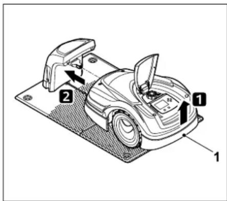
Lift the robotic mower slightly by the carrying handle (1) to relieve the weight on the drive wheels. Push the machine, resting on its front wheels, into the docking station.
- After pressing the OK button, enter the PIN code. The robotic mower will then search for the wire signal and save it automatically. This process takes several minutes.
(⇒ 9.11)

No PIN code is required in the safety level "None".
11.17 Service
1. Blade change:
Installation of a new mowing blade is confirmed with OK.

If the blade has been in use for more than 200 hours, the message "Replace mowing blade" appears. ( 16.4)
2. Find wire break:
If the red LED on the docking station flashes rapidly, there is a break in the perimeter wire. ( 13.1)
• Find wire break ( 16.7)
3. Reset settings:
The robotic mower is reset to the factory defaults with OK, the installation assistant is restarted. ( 9.6)
- Enter the PIN code after pressing the OK button.

No PIN code is required in the safety level "None".

12. Perimeter wire

Before routing the perimeter wire, particularly prior to initial installation, read the entire section and plan the routing in detail.

Perform initial installation using the installation assistant. ( 9.)
Should you require support, your STIHL specialist dealer will be pleased to assist you with preparation of the mowing area and installation of the perimeter wire.
Check the installation of the perimeter wire before it is finally secured in place. ( 9.) Adjustments to the wire routing are generally necessary in the vicinity of corridors, confined areas or no-go areas.
Deviations can occur
- if the technical limits of the robotic mower are reached, for example with very long corridors or when routing the perimeter wire in the vicinity of metal objects or above metal under the lawn (e.g. water pipes and power supply lines),
- if the mowing area is structurally altered for using the robotic mower.

The wire clearances specified in this Instruction Manual are adapted to routing of the perimeter wire on the lawn area.
The perimeter wire can also be buried up to a depth of 10 cm (e.g. using a cable-laying machine).
Burial in the ground generally influences signal reception, particularly if flagstones or paving stones are laid over the perimeter wire. The robotic mower may travel along at a greater offset to the perimeter wire, requiring more space in corridors, confined areas and when travelling along edges. Adapt wire routing if necessary.
12.1 Planning routing of the perimeter wire

Study the installation examples at the end of this instruction manual. ( 27.)
Include no-go areas, corridors, secondary areas, guide loops and reserve wire during routing of the perimeter wire, in order to prevent subsequent corrections.
- Define the location of the docking station. ( 9.1)
- Either remove obstacles from the mowing area, or include no-go areas. ( 12.9)
- Perimeter wire:
The perimeter wire must be routed in a continuous loop around the entire mowing area.
Maximum length:
500 m

For mowing areas < 100 m² or a wire length < 175 m, the accessory AKM 100 must be installed together with the perimeter wire. (⇔ 9.9)
• Corridors and secondary areas:
For automatic mowing, join all parts of the mowing area by means of corridors. ( 12.11)
If there is insufficient space to do so,
secondary areas must be
installed. ( 12.10)
- Observe the clearances when routing the perimeter wire ( 12.5):
for adjoining areas that can be travelled on (stepped area height of less than +/- 1 cm, e.g. paths): 0 cm
for corridors: 22 cm
for high obstacles (e.g. walls, trees):
28 cm
minimum wire clearance in confined areas: 44 cm
or water features and potential sudden drops (edges, steps): 100 cm
- Corners:
Avoid routing at acute angles (less than 90°).
- Guide loops:
If offset drive home (passage) is to be used, guide loops must be installed for corridors or for the external docking station. ( 12.12)
- Reserve wire:
Reserve wire should be installed at several points to make it easier to subsequently change the routing of the perimeter wire. ( 12.15)
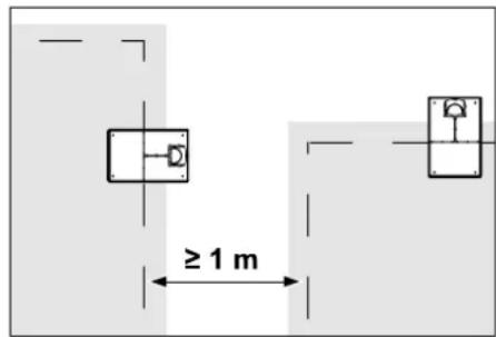
Mowing areas must not overlap. Maintain a minimum clearance of ≥ 1 m between the perimeter wires of two mowing areas.

Coiled up residual pieces of perimeter wire can cause malfunctions and must be removed.
12.2 Making a sketch of the mowing area

During installation of the robotic mower and the docking station, it is recommendable to make a sketch of the mowing area. A page has been provided at the start of this Instruction Manual for this purpose.
The sketch should be modified in the event of subsequent changes.
Content of the sketch:
- Contour of the mowing area including important obstacles, borders and any no-go areas which the robotic mower must not mow. ( 27.)
- Position of the docking station ( 9.8)
– Position of perimeter wire
After a short while, the perimeter wire is overgrown and is no longer visible. Make a note of the routing of the wire around obstacles in particular. ( 9.9)
– Position of the wire connectors
After a short while, the wire connectors used are no longer visible. Their position should be noted in order to replace them as required. ( 12.16)
12.3 Routing the perimeter wire

Only use genuine fixing pins and genuine perimeter wire.
Installation kits with the necessary installation material are available as an accessory from the STIHL specialist dealer. ( 18.)
The routing direction (clockwise or counterclockwise) is freely selectable according to requirements.
Never pull out fixing pins using the perimeter wire – always use a suitable tool (e.g. universal pliers).
Make a sketch of the perimeter wire routing. ( 12.2)
• Install the docking station. ( 9.8)
- Route the perimeter wire around the mowing area and any obstacles beginning at the docking station ( 12.9) and fasten it to the ground using fixing pins. Check the clearances using the iMow Ruler. ( 12.5) Follow the instructions in the "Initial installation" section. ( 9.9)
- Connect the perimeter wire. (⇒ 12.4)

Note:
Avoid excessive tensile stress on the perimeter wire to prevent wire breaks. In particular when using a wire routing machine, make sure that the perimeter wire unwinds loosely from the spool.
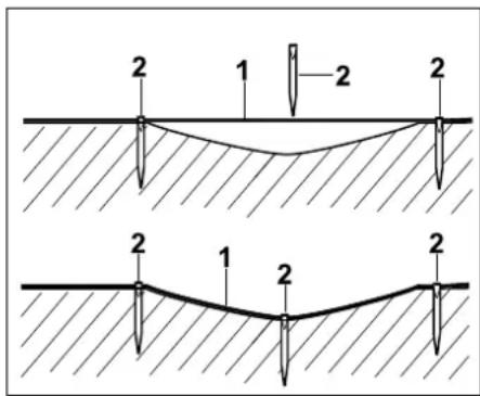
The perimeter wire (1) is routed above ground and attached with additional fixing pins (2) in case of unevenness. This prevents the wire being cut by the mowing blade.
12.4 Connecting the perimeter wire
- Disconnect the mains plug and then remove the docking station cover.
- Insert the perimeter wire into the cable guides of the floor plate, guide it through the socket, strip the ends and connect to the docking station. Follow the instructions in the "Initial installation" section. ( 9.10)
- Install the docking station cover and then connect the mains plug.
- Check the wire signal. (⇔ 9.11)


- Check docking. (→ 15.6)
If necessary, correct the position of the perimeter wire in the area of the docking station.
12.5 Wire clearances – use iMow Ruler
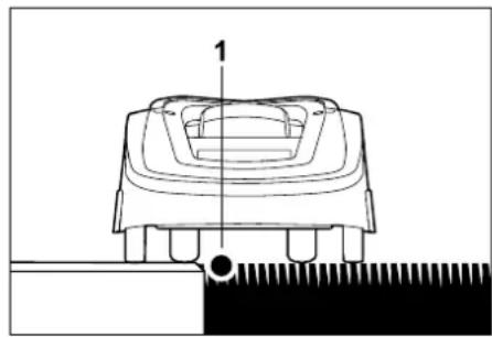
natural_image
Technical line drawing of a mechanical component with no visible text or symbols
The perimeter wire (1) can be routed without clearance along obstacles that can be travelled on such as patios and paths. The robotic mower then travels with one rear wheel outside the mowing area. Maximum stepped area to the turf: +/- 1 cm

Take care not to damage the perimeter wire when tending to the lawn edge. If necessary, install the perimeter wire at a slight distance (2-3 cm) from the lawn edge.

The clearances of the iMow Ruler are defined such that the robotic mower can travel along the edge with a track offset of 6 cm without interruption (without bumping against obstacles). Reduce the track offset if necessary (too much unmown grass on edge). ( 11.11)
Measuring wire clearances with the iMow Ruler:
To ensure the correct clearance from the perimeter wire to the edge of the lawn and to obstacles, the iMow Ruler should be used for measuring the distances.
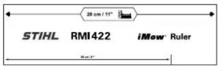
High obstacle:
Clearance between a high obstacle and the perimeter wire.

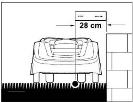
The robotic mower must run completely within the mowing area and must not touch the obstacle.
Through the clearance of 28 cm, the robotic mower travels along the perimeter wire without bumping into the obstacle in the corner around a high obstacle.
Wire routing around high obstacles:
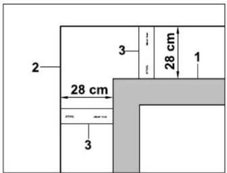
When routing around high obstacles (1) such as wall corners or high flowerbeds, the wire clearance must be maintained at the corners to prevent the robotic mower from scraping against the obstacle. Route the perimeter wire (2) with the aid of the iMow Ruler (3) as illustrated.
Wire clearance: 28 cm
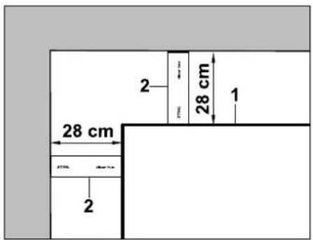
When routing the perimeter wire (1) at an internal corner at a high obstacle, measure the wire clearance with the iMow Ruler (2).
Wire clearance: 28 cm
Measuring the height of obstacles:
The robotic mower can cross adjoining areas such as paths if the height of the stepped area is less than +/- 1 cm.
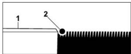
Height difference to obstacle that can be travelled on (1) is less than +/- 1 cm: route the perimeter wire (2) without clearance to the obstacle.
12.6 Acute corners
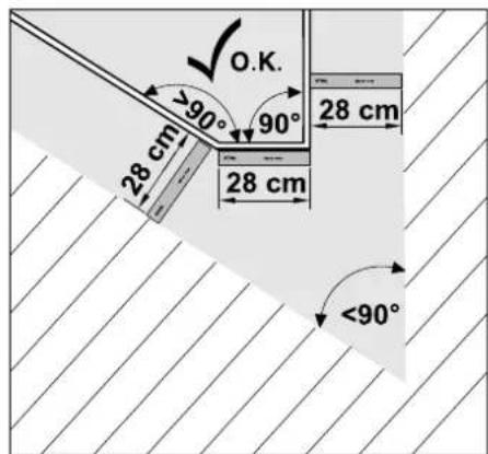
The perimeter wire is routed as illustrated in acutely angled lawn corners (< 90°). The two angles must have a clearance of at least 28 cm so that the robotic mower can follow the edge.
12.7 Confined areas

If confined areas are to be installed, switch off offset drive home (passage) ( 11.14) or install guide loops. ( 12.12)
The robotic mower travels automatically in all confined areas, provided the minimum wire clearance is maintained. Narrower areas of the mowing area must be blocked off through appropriate routing of the perimeter wire.
If two mowing areas are linked via a narrow passage that can be travelled on, a corridor can be installed. ( 12.11)
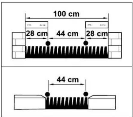
The minimum wire clearance is 44 cm.
This results in the following space requirements in confined areas:
- between high obstacles with a height +/- 1 cm, such as walls 100 cm,
- between adjoining areas that can be travelled on with a stepped area height of less than +/- 1 cm, such as paths 44 cm.
12.8 Installing linking sections
The robotic mower ignores the perimeter wire signal if the wires are routed parallel and close together. Linking sections must be installed
- where secondary areas are to be installed, (⇒ 12.10)
- where no-go areas are necessary.
(⇒ 12.9)

STIHL recommends laying linking sections together with the relevant no-go areas or secondary areas during wire routing.
In the case of retrospective installation, the wire loop must be cut and linking sections must then be integrated using the wire connectors supplied. ( 12.16)
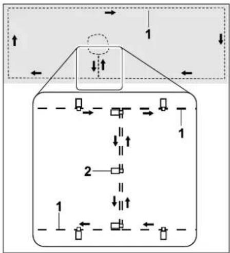
flowchart
graph TD
    A["Top Center"] --> B["Arrow 1"]
    B --> C["Arrow 2"]
    C --> D["Arrow 1"]
    D --> E["Arrow 2"]
    E --> F["Arrow 1"]
    F --> G["Arrow 2"]
    G --> H["Arrow 1"]
    H --> I["Arrow 2"]
    I --> J["Arrow 1"]
    J --> K["Arrow 2"]
    K --> L["Arrow 1"]
    L --> M["Arrow 2"]
    M --> N["Arrow 1"]
    N --> O["Arrow 2"]
    O --> P["Arrow 1"]
    P --> Q["Arrow 2"]
    Q --> R["Arrow 1"]
    R --> S["Arrow 2"]
    S --> T["Arrow 1"]
    T --> U["Arrow 2"]
    U --> V["Arrow 1"]
    V --> W["Arrow 2"]
    W --> X["Arrow 1"]
    X --> Y["Arrow 2"]
    Y --> Z["Arrow 1"]
In linking sections, the perimeter wire (1) must be routed parallel, the wires must not cross and must be close to one another. Attach the linking section to the ground with a sufficient number of fixing pins (2).
12.9 No-go areas
No-go areas have to be installed
- around obstacles that the robotic mower must not touch,
- around obstacles that are not sufficiently sturdy,
- around obstacles that are too low. Minimum height: 8 cm
STIHL recommends
- blocking off obstacles by means of no-go areas or removing them,
- checking no-go areas after initial installation or after changes to the wire installation using the "Test edge" command. (⇔ 11.14)
Clearance for routing the perimeter wire around a no-go area: 28 cm
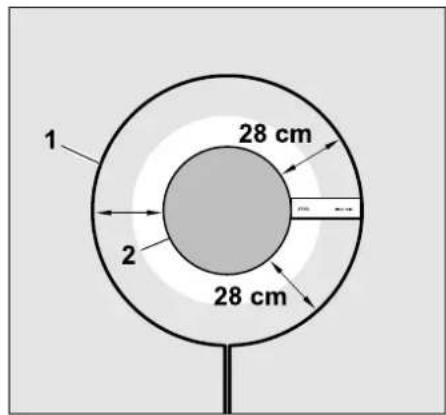
The robotic mower travels along the perimeter wire (1) around the obstacle (2) without bumping into it.
To guarantee robust operation, no-go areas should be more or less round and not oval, angular or inwardly curved.
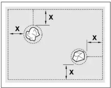
No-go areas must have a minimum diameter of 56 cm.
The clearance to the edge loop (X) must be greater than 44 cm.
Recommendation: No-go areas should have a maximum diameter of 2 - 3 m.
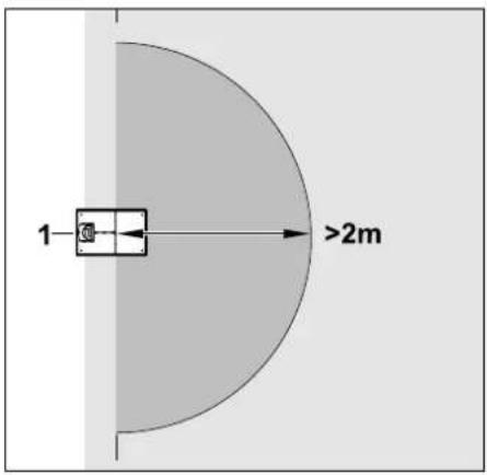
In order for docking to take place smoothly, no no-go area must be installed within a radius of at least 2 m around the docking station (1).
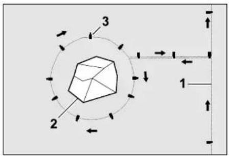
flowchart
graph TD
    A["3"] --> B["2"]
    B --> C["1"]
    C --> D["↑"]
    style A fill:#f9f,stroke:#333
    style B fill:#ccf,stroke:#333
    style C fill:#cfc,stroke:#333
    style D fill:#fcc,stroke:#333
Route the perimeter wire (1) from the edge to the obstacle with the correct clearance (use iMow Ruler) around the obstacle (2) and attach it to the ground with a sufficient number of fixing pins (3). Then route the perimeter wire back to the edge again.
The perimeter wire must be routed parallel in a linking section. It is important to observe the routing direction around the no-go area ( 12.8)
12.10 Secondary areas
Secondary areas are parts of the mowing area that cannot be mown fully automatically by the robotic mower because access is not possible. In this manner, several separate mowing areas can be surrounded with a single perimeter wire. The robotic mower must be manually taken from one mowing area to another. The mowing operation can be initiated via the commands "Start mowing" ( 11.5) or "Start time-delayed mowing" ( 11.5).
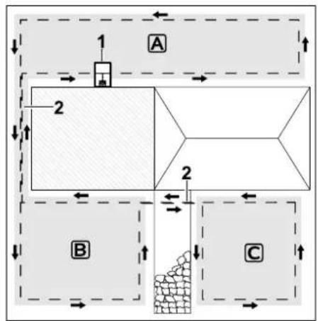
The docking station (1) is installed in the mowing area A, which is cut fully automatically in accordance with the mowing plan.
The secondary areas B and C are connected to the mowing area A via the linking sections (2). The perimeter wire must be routed in the same direction in all areas – do not cross perimeter wires in the linking areas.
- Activate secondary areas in the "Settings – Installation" menu. (⇔ 11.14)
12.11 Corridors
If several mowing areas have to be mown (e.g. mowing areas in front of and behind the house), these can be linked by installing a corridor. This allows all the mowing areas to be mown automatically.
In corridors, the lawn is only mown along the path of the perimeter wire. If necessary, activate automatic edge mowing or mow the corridor area manually on a regular basis. ( 11.5), ( 11.14)
If corridors are to be installed, switch off offset drive home (passage) ( 11.14) or install guide loops. ( 12.12)
The specified wire clearances and the corridor template are adapted to routing of the perimeter wire on the lawn area. The dimensions will deviate if the perimeter wire is routed very deeply, e.g. under stone paving. Check the function and adapt the wire routing if necessary.
Requirements:
- Minimum width is 88 cm between solid obstacles in the corridor area and 22 cm between paths that can be travelled on.
In longer corridors, a slightly increased space requirement should be taken into account depending on the ground conditions. Longer corridors should always be installed as centrally as possible between obstacles.
– The corridor can be travelled on freely.
- At least 1 starting point must be defined in the area of the second mowing area. (→ 11.15)
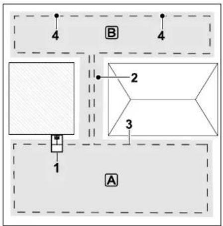
The docking station (1) is installed in mowing area A. Mowing area B is linked to mowing area A by means of a corridor (2). The perimeter wire (3) can be continuously followed by the robotic mower. In order to mow mowing area B, starting points (4) must be defined.
(⇒ 11.15)
Individual mowing operations can then be started at the starting points, depending on the setting (starting frequency).
Installing the start and end of the corridor:
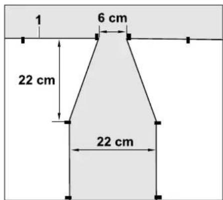
The perimeter wire (1) must be routed in a funnel shape as illustrated at the start and end of a corridor. This prevents the robotic mower from accidentally driving into the corridor during mowing.

The dimensions are very much dependent on the environment and the terrain. For corridors with a funnel-shaped start or end, always check whether the robotic mower can pass through it.
Route the perimeter wire roughly one device length to the left and right of the corridor entrance.
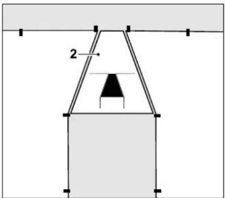
Use the corridor template (2) supplied for installing the funnel-shaped entrance and exit areas.
Installing the corridor:
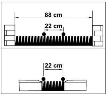
Wire clearance in corridors: 22 cm
This results in the following space requirements:
- between high obstacles (over 1 cm in height - e.g. walls):
88 cm.
- between paths/obstacles that can be travelled on (less than 1 cm in height - e.g. paths): 22 cm.
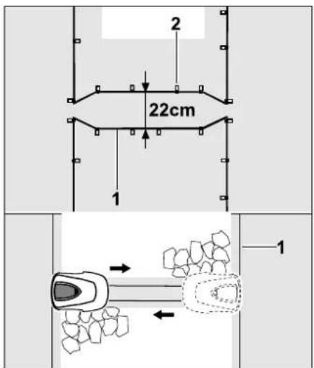
In corridors, the perimeter wire (1) must be routed parallel and attached to the ground with a sufficient number of fixing pins (2). At the start and end of the corridor, funnel-shaped entrance and exit areas must be installed.
12.12 Guide loops for offset drive home
If offset drive home is activated, guide loops must be provided
- if an external docking station has been installed
or
- if there are corridors or confined areas in the mowing area.
Function:
When the robotic mower follows the perimeter wire offset at a distance, it crosses one of these guide loops during the drive home. It then travels to the perimeter wire and on to the docking station.
Guide loops with an external docking station:
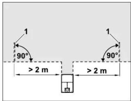
To the right and left of the access to the external docking station, two guide loops (1) have to be installed at an angle of 90^ to the perimeter wire.
Minimum clearance to access: 2 m
Guide loops with corridors:
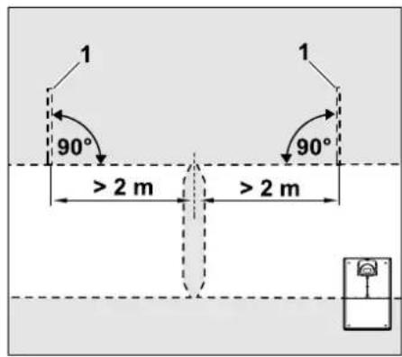
To the right and left of the corridor access, two guide loops (1) have to be installed at an angle of 90^ to the perimeter wire.
These must always be located in the part of the mowing area that can only be accessed via a corridor.
Minimum clearance to corridor access: 2 m

If several consecutive corridors are installed, guide loops must be installed in each of the relevant mowing areas.
Installation of a guide loop:
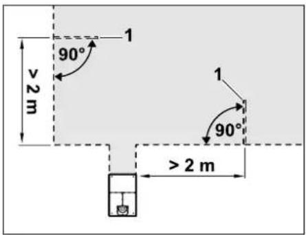
Guide loops must not be installed in the vicinity of corners.
Minimum clearance to corners: 2 m
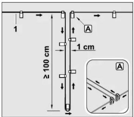
Install the guide loop in the lawn area as illustrated. The perimeter wire (1) must be fastened to the ground with two fixing pins at the edge A and must not be crossed. Minimum length: 100 cm
Width: 1 cm
- Attach the guide loop to the ground with a sufficient number of fixing pins.
12.13 Accurate mowing along edges

At a track offset of 6 cm, a strip with a width of up to 26 cm is left unmown along high obstacles. If necessary, edging stones can be laid around high obstacles.
Minimum width of edging stones:
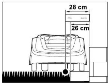
Route the perimeter wire at a clearance of 28 cm to the obstacle. To ensure that the lawn edge is mown completely, the edging stones must have a width of at least 26 cm. If wider edging stones are laid, the lawn edge is cut even more precisely.
12.14 Sloping terrain in the mowing area

Note:
For a robust installation, it is recommended to route the perimeter wire on a maximum incline of +/- 10° (17%). The wire can be routed on an incline of up to +/- 15° (27%), however this can significantly increase the effort and level of adjustment involved in routing the wire. Inclines should also always be noted in garden sketches.
In order for the robotic mower to automatically mow a slope in the mowing area (incline up to 15°) without any trouble, the perimeter wire must be installed in the slope with a minimum clearance to the edge of the incline.
A clearance of at least 100 cm must be observed for water features and sudden drops like edges and steps.
Slope with an incline of 5^ - 15^ :
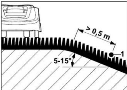
If there is a slope with an incline of 5^-15^ in the mowing area, the perimeter wire can be routed below the top edge of the slope in the slope as illustrated. The minimum clearance (0,5 m) from the top edge of the slope to the perimeter wire must be taken into account for trouble-free operation of the robotic mower.
Slope with an incline >15^ :
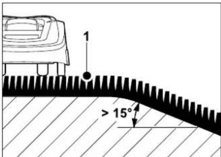
If there is a slope with an incline >15^ in the mowing area, it is recommended that the perimeter wire (1) be routed in the flat area before the top edge of the slope. The top edge and area of the slope are not mown.
12.15 Installing reserve wire
Reserve wire installed at regular intervals makes it easier to make any necessary corrections such as subsequently changing the position of the docking station or the routing of the perimeter wire. In particular, reserve wire should be installed near difficult passages.
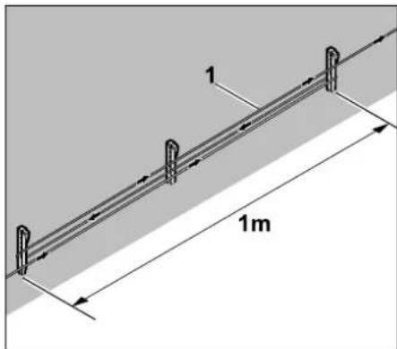
Route perimeter wire (1) as illustrated between 2 fixing pins spaced approx. 1 m apart. Attach the reserve wire to the ground in the centre using a further fixing pin.
12.16 Using wire connectors
In order to extend the perimeter wire or to connect loose wire ends, only the gel-filled wire connectors available as accessories may be used. They prevent premature wear (e.g. corrosion of the wire ends) and ensure optimal connections. Make a note of the positions of the wire connectors on the sketch of the mowing area. ( 12.2)
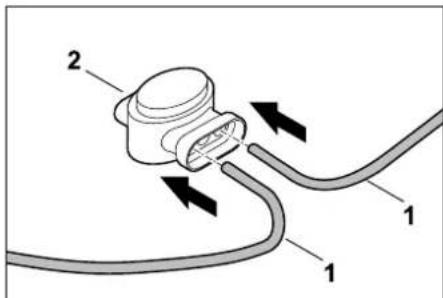
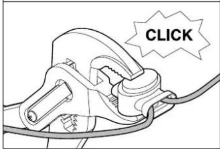
Insert loose, unstripped wire ends (1) to the stop in the wire connector (2). Press the wire connector together using suitable pliers – ensure correct engagement.
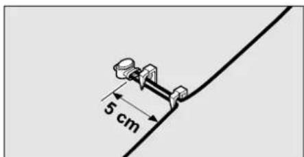
Attach the perimeter wire strain relief to the ground with two fixing pins as illustrated.
12.17 Narrow edge clearances
It is possible to reduce the wire clearance to a high obstacle to 22 cm on a straight section (not at corners). This will result in a larger mown area.
Sufficient clearance (at least 5 cm) between the robotic mower and obstacles must be ensured for edge following ( 9.12), ( 11.14). If necessary, increase the wire clearance to the obstacles.

Narrow edge clearances should always be noted in the garden sketch. ( 12.2)
Narrow edge clearances at the internal corner:
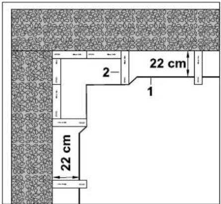
Route the perimeter wire (1) as illustrated at the internal corner. Use the iMow Ruler (2).
Narrow edge clearances at the external corner:
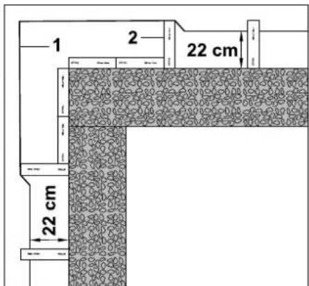
Route the perimeter wire (1) as illustrated at the external corner. Use the iMow Ruler (2).
13. Docking station
13.1 Docking station controls
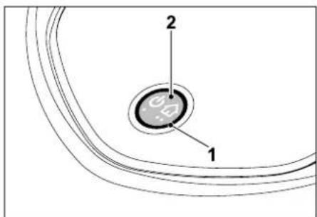
A circular red LED (1) provides information on the status of the docking station and the wire signal.
Function button (2):
– Switching docking station on and off
- Activating Homecall
- Activating find wire break
LED does not illuminate:
- Docking station and wire signal are switched off.
LED illuminates continuously:
- Docking station and wire signal are switched on.
- Robotic mower is not docked.
LED flashes slowly (2 seconds on – briefly off):
- Robotic mower is docked, battery is charging if required.
- Docking station and wire signal are switched on.
LED flashes rapidly:
- Perimeter wire is interrupted - wire break or wire is not correctly connected to the docking station.(⇔ 16.7)
LED illuminates for 3 seconds, followed by 1 second pause:
- Homecall was activated.
LED gives 3 short flashes, 3 long flashes, 3 short flashes, followed by approx. 5 second pause (SOS signal):
- Error in the docking station.
Switching the docking station on and off:
The docking station is switched on and off automatically during automatic operation.

If the robotic mower is not docked, briefly pressing the button activates the docking station. The wire signal remains active for 48 hours if the robotic mower has not previously docked.
Pressing the button for 2 seconds switches off the docking station.
Activating Homecall:
Briefly press the button twice within 2 seconds during a mowing operation.

The robotic mower ends the running mowing operation, searches for the perimeter wire and returns to the docking station to recharge the battery. No further mowing operation takes place in the current active time.

Homecall remains active until the robotic mower is docked. Homecall can also be ended by pressing the button on the docking station twice again.
14. Notes on mowing
14.1 General
The robotic mower is designed for the automatic mowing of lawns. The grass is kept short through continuous mowing. The result is a perfect, thick lawn.
Lawns that have not previously been mown using a conventional lawn mower will only be mown neatly following several mowing operations. Especially in the case of high grass, a good cutting pattern is only achieved after a few mowing operations.
In hot, dry conditions, the lawn should not be kept too short as it will otherwise be burnt by the sun and become unsightly.
The cutting pattern will be better with a sharp blade than with a blunt one; the blade should therefore be replaced regularly.
14.2 Mulching
The robotic mower is a mulching mower.
During mulching, the grass clippings are further shredded in the mowing deck housing after cutting. They then fall back into the turf, where they remain and decompose.
The finely shredded clippings return organic nutrients to the lawn, serving as a natural fertiliser. Fertiliser requirements are thereby reduced significantly.
14.3 Active times
During the active times, the robotic mower is allowed to leave the docking station and mow the lawn. During these times, mowing operations, charging operations and rest periods take place. The robotic mower automatically distributes the mowing and charging operations between the available time windows.
During installation, active times are automatically distributed over the entire week. Time reserves are taken into account – this ensures perfect lawn care, even if individual mowing operations cannot take place, (e.g. due to rain).

During the active times, third parties must keep out of the danger area. The active times should be adapted accordingly. Moreover, the applicable local regulations on the use of robotic mowers as well as the information in the "For your safety" section ( 6.) must be observed and the active times changed accordingly in the "Mowing plan" menu as required. ( 11.7) In particular, you should check the times of the day and night at which it is permissible to use the machine with the responsible authorities.
14.4 Mowing duration
The mowing duration specifies how many hours per week the lawn is to be mown. It can be extended or reduced. ( 11.8)
The mowing duration corresponds to the time during which the robotic mower mows the lawn. Times during which the battery is charged are not part of the mowing duration.
During initial installation, the robotic mower automatically calculates the mowing duration based on the specified size of the mowing area. This reference value is based on a normal lawn under dry conditions.
For 100 m ^2 , the robotic mower needs on average:
RMI 422: 120 minutes
RMI 422 P,
RMI 422 PC: 100 minutes
14.5 Home area (RMI 422 PC)
The robotic mower identifies its location using the built-in GPS receiver. During each edge following run to check the correct wire routing ( 9.12) and when entering in the starting points ( 11.15), the robotic mower stores the coordinates of the most westerly, easterly, southerly and northerly point.
This area is defined as the home area and the robotic mower can be used here. The coordinates are updated each time edge following is repeated.
When GPS protection is activated, the owner of the machine is notified if the machine is operated outside the home area. The PIN code is also requested on the robotic mower display.
15. Operating the machine
15.1 Preparation
An installation assistant is available for initial installation. ( 9.)
The robotic mower should be charged and operated at an ambient temperature between +5°C and +40°C.
• Install the docking station ( 9.8)
- Route ( 9.9) and connect ( 9.10) the perimeter wire
- Remove foreign bodies (e.g. toys, tools) from the mowing area
- Charge the battery (⇒ 15.7)
- Set the time and date (⇒ 11.11)
- Check the mowing plan and adapt if necessary – in particular it must be ensured that third parties keep away from the danger area during active times. ( 11.6)
Mow very high grass until it is short using a conventional lawn mower prior to use of the robotic mower (e.g. following a lengthy break).
15.2 Flap
The robotic mower is equipped with a flap which protects the display from the weather and from inadvertent operation. If the flap is opened during use of the robotic mower, operation is stopped and the mowing blade and robotic mower come to a standstill.
Opening the flap:
For safety reasons, the Stop button must be pressed before opening the flap during operation of the robotic mower.
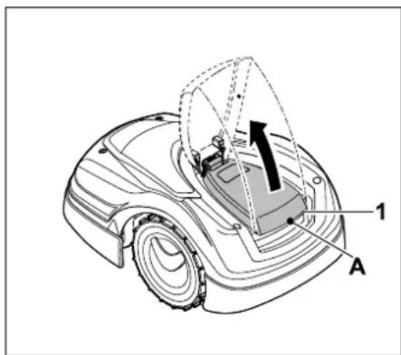
Grasp the flap (1) at the lifting point (A) and release upwards by pulling lightly. Open the flap as far as it will go.
The opened flap can be removed upwards from the machine. This design is implemented for safety reasons: this ensures that the machine cannot be lifted and carried by the flap.
Closing the flap:
Carefully fold the flap downwards and allow to engage.
The robotic mower can only be operated when the flap is fully engaged.
15.3 Adapting the programming
The current programming can be seen in the Mowing plan or, in the case of model RMI 422 PC, in the iMow app. ( 11.6) The mowing plan is calculated based on the size of the mowing area during installation or during the creation of a new mowing plan.
The active times and the mowing duration can be changed individually, the required mowing operations themselves are automatically distributed over the possible active times. If required, several mowing or charging operations can run during an active time. If required, the edge of the mowing area can be cut automatically at regular intervals.
(⇒ 11.14)
Up to three different active times per day are possible. ( 11.7)
If the robotic mower has to travel to specific areas of the mowing area, starting points must be defined. ( 11.15)
Under certain circumstances (e.g. warm weather or generous time window), not all the active times may be necessary for optimal lawn care.
Changing the active times: (⇔ 11.7)
– Additional active times for further mowing operations.
- Adapting the time window, e.g. to prevent mowing during the morning or night.
- Omitting individual active times because the mowing area is e.g. being used for a party.
Extending the mowing duration: ( 11.8)
– There are areas which are not mown sufficiently, e.g because the mowing area has many corners.
- Intensive grass growth during the growing period.
– Particularly dense lawn.
Reduction of the mowing duration: ( 11.8)
– Reduced grass growth due to heat, cold or dryness.
Creation of a new mowing plan: ( 11.6)
– The size of the mowing area has been changed.
New installation: ( 11.14)
– New location of the docking station.
– Initial operation on a new mowing area
15.4 Automatic mowing
- Switching on automatic mowing:
When automatic mowing is switched on, the Automatic symbol appears next to the battery symbol in the display. ( 11.5)
• Starting mowing operation:
The mowing operations are automatically distributed between the available active times. ( 11.7)
• Ending mowing operation:
When the battery is discharged, the robotic mower automatically travels back to the docking station. ( 15.6)
A running mowing operation can be ended manually at any time using the STOP button. ( 5.1)
Activating Homecall on the docking station also ends the running mowing operation immediately. ( 13.1)
RMI 422 PC:
The mowing operation can also be ended using the app – send the robotic mower to the docking station. ( 10.)

Mowing areas that the robotic mower reaches via a corridor are only mown if starting points have been defined in the relevant area.
15.5 Mowing independently of active times
- Activate the docked robotic mower by pressing a button. This also switches on the docking station.
Mowing areas with docking station:
- In order to mow a part of the mowing area that can only be reached via a corridor, carry the robotic mower there.

-
Immediate mowing:
Call up the command Start mowing
(⇒ 11.5).
The mowing operation starts immediately and continues until the selected time.
-
Time-delayed mowing:
Call up the command Start time-delayed mowing. ( 11.5)
The mowing operation starts at the selected start time and continues until the selected end time.
• RMI 422 PC:
Start mowing using the app. ( 10.) The mowing operation starts at the selected start time and continues until the selected end time.
- Ending mowing manually:
A running mowing operation can be ended at any time using the STOP button. ( 5.1)
Activating Homecall on the docking station also ends the running mowing operation immediately. ( 13.1)
RMI 422 PC:
The mowing operation can also be ended using the app – send the robotic mower to the docking station. ( 10.)

If necessary, the robotic mower charges the battery in the interim and then continues the mowing operation until the selected end time.
Secondary areas:

If the battery runs flat before the selected end time, the mowing operation is shortened accordingly.
15.6 Docking the robotic mower
Docking during automatic operation:
The robotic mower automatically travels to the docking station when the active time ends or when the battery is discharged.
Forcing docking:

- Activate the command Drive to docking station. ( 11.5)
During a mowing operation,
Homecall can also be activated on the docking station.

- If necessary, switch on the docking station ( 13.1)
- RMI 422 PC:
Send the robotic mower to the docking station in the app. (⇔ 10.)

After docking, no further mowing operation takes place in the current active time.
Manual docking:
- Push the robotic mower into the docking station by hand.
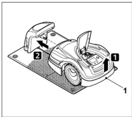
Lift the robotic mower slightly by the carrying handle (1) to relieve the weight on the drive wheels. Push the machine, resting on its front wheels, into the docking station.
15.7 Charging the battery
Only charge the battery via the docking station.
Never remove the battery and charge it using an external charger.
Automatic charging:
During mowing, charging occurs automatically when the robotic mower docks into the docking station at the end of the mowing operation.
Starting charging manually:
- Following use in secondary areas, return the robotic mower to the mowing area and dock it. ( 15.6)
- Dock the robotic mower following interruption of a mowing operation. ( 15.6)
- If necessary, end standby mode of the robotic mower by pressing a button. Charging starts automatically.
Charging:
During charging, the text "Charging battery" is displayed in the status screen.

A plug symbol appears instead of the battery symbol in the information area of the display in all the other menus.

The charging time varies and is automatically adapted to the subsequent period of use.

In the event of charging problems, a corresponding message appears on the display. ( 24.)
The battery is only charged when the voltage falls below a certain value.
Charge state:
The momentary charge state can be seen in the status screen when the relevant display is selected.
(⇒ 11.13)

In all other menus, the battery symbol in the information area of the display serves to indicate the charge state. ( 11.3)

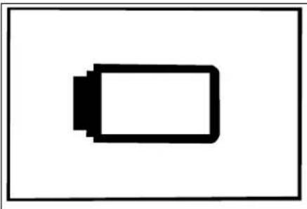
natural_image
Simple black-and-white diagram of a battery symbol inside a rectangle (no text or labels)
If the battery charge is too low, the corresponding battery symbol appears. In this case, place the robotic mower in the docking station to recharge.
16. Maintenance

Risk of injury!
Carefully read the section "For your safety" ( 6.), particularly the subsection "Maintenance and repairs" ( 6.9), and follow all safety instructions exactly before performing any maintenance or cleaning operations on the machine.
Activate the disabling device prior to any maintenance or cleaning work. ( 5.2)
Disconnect the mains plug before performing any maintenance operations on the docking station.
Always wear gloves when carrying out any maintenance work, particularly when working on the mowing blade.


16.1 Maintenance schedule
The maintenance intervals are based on the operating hours among other factors. The relevant "Mowing hours" counter can be called up in the "Information" menu. (⇔ 11.9)
The specified maintenance intervals must be strictly observed.
Maintenance operations on days with active times:
- Visually inspect the general condition of the machine and the docking station.
- Check the display – check the current time and start of the next mowing operation.
- Check the mowing area and remove foreign bodies, etc. as required.
- Check that the battery is being charged.
(⇒ 15.7)
Weekly maintenance operations:
- Clean the machine. (⇒ 16.2)
- Visually inspect the mowing blade, blade fastening and mowing deck for damage (notches, cracks, fractures, etc.) and wear. (⇒ 16.3)
Every 200 hours:
- Replace the mowing blade. A corresponding reminder appears on the display. ( 16.4)
Annual maintenance operations:
- STIHL recommends an annual inspection by a STIHL specialist dealer during the winter months.
Here, maintenance of the battery, electronics and software in particular is performed.

In order for your specialist dealer to perform all the maintenance operations correctly, set the safety level to "None" or give your specialist dealer the appropriate PIN code.
16.2 Cleaning the machine
Treating the machine carefully will protect it against damage and extend its service life.
Cleaning and maintenance position:

Only perform cleaning work on the mowing blades when wearing thick work gloves and exercising extreme care.
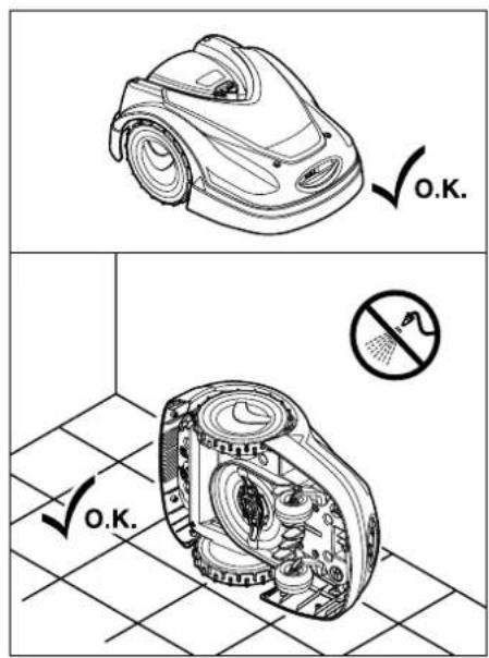
Place the machine on a firm, level and flat surface for cleaning the top of the machine (hood, flap). To clean the
underside of the machine (mowing blade, mowing deck), tilt the robotic mower onto its left or right side as illustrated and lean it against a wall.
- Clean off dirt with a brush or a cloth. In particular, also clean the mowing blade and the docking station.
- Detach accumulated clipping deposits in the housing and in the mowing deck beforehand using a stick.
- If necessary, use a special cleaner (e.g. STIHL special cleaner).
- Regularly remove the carrier plate and remove grass residues. (⇔ 16.6)

The carrier plate must be cleaned frequently in wet weather. Dirt deposits between the carrier plate and the mowing deck housing create friction, leading to increased power consumption.
16.3 Checking the mowing blade wear limits

Risk of injury!
A worn mowing blade may break off and cause serious injuries. The instructions for blade maintenance must therefore always be observed. Mowing blades are subject to differing degrees of wear depending on the location and duration of use. If you use the machine on sandy ground or use it frequently under dry conditions, the mowing blade will be subjected to greater loads and will wear more quickly than normal.
Replace the mowing blade at least every 200 operating hours – do not resharpen. ( 16.5)
- Activate the disabling device. (⇒ 5.2)
- Tilt the robotic mower onto its side and lean it securely against a stable wall. Carefully clean the mowing deck and mowing blade. ( 16.2)
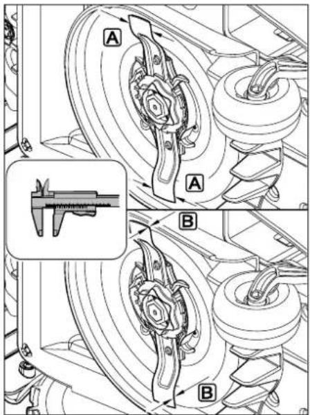
Check blade width A and blade thickness B using a slide calliper. If the blade width is less than 25 mm or the blade thickness is less than 1,3 mm at any point, the mowing blade must be replaced.
16.4 Removing and installing the mowing blade

The mowing blade is designed for a service life of 200 hours. After this period, a corresponding message appears in the display.
- Activate the disabling device ( 5.2) and wear gloves.
- Tilt the robotic mower onto its side and lean it securely against a stable wall. Carefully clean the mowing deck and mowing blade. (⇒ 16.2)
Removing the blade:
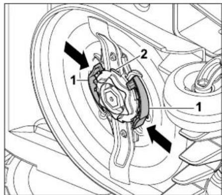
Push in both tabs (1) on the carrier plate with one hand and hold. Remove the fastening nut (2) with your other hand.
Remove the mowing blade together with the fastening nut.


Installing the mowing blade:

Risk of injury!
Check the blade for damage before installing. The blade must be replaced if notches or cracks are identified or if its width is less than 25 mm, or its thickness is less than 1.3 mm at any point. ( 16.3)
The carrier plate and the fastening nut must also be replaced if damaged (e.g. broken, worn). The fastening nut in particular must engage cleanly in the carrier plate.
- Clean the blade, carrier plate and fastening nut prior to installation.
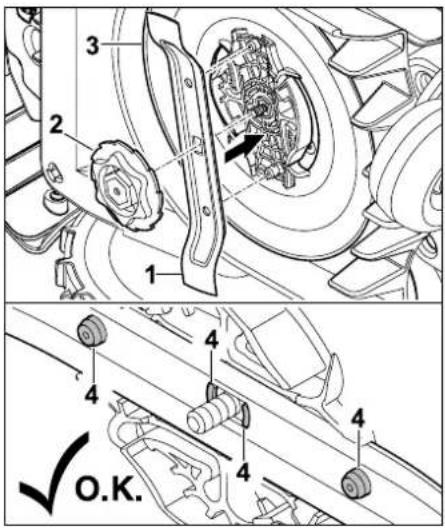
Fit the mowing blade (1) and fastening nut (2) on the carrier plate (3) as illustrated. Ensure correct position of the retainers (4) in the mowing blade.
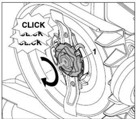
Screw on the fastening nut (1) as far as possible. Several clicks are audible during tightening. Ensure secure seating of the mowing blade by shaking carefully.
- Following installation of a new mowing blade, confirm the blade replacement in the "Service" menu. (⇔ 11.17)
16.5 Sharpening the mowing blade
Never re-sharpen blades.
STIHL recommends always replacing a blunt blade with a new one.

Only new mowing blades are balanced with the necessary precision and guarantee proper functioning of the machine as well as low noise emissions.
16.6 Removing and installing the carrier plate

The carrier plate can be removed in order to clean the mowing deck.
- Activate the disabling device ( 5.2) and wear gloves.

- Tilt the robotic mower onto its side and lean it securely against a stable wall. Carefully clean the mowing deck and mowing blade. ( 16.2)
Removing the carrier plate:
- Remove the mowing blade. (⇒ 16.4)
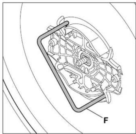
natural_image
Technical line drawing of a mechanical assembly with labeled component 'F' (no text or symbols beyond label)
Insert the puller (F) and turn anti-clockwise to the stop.
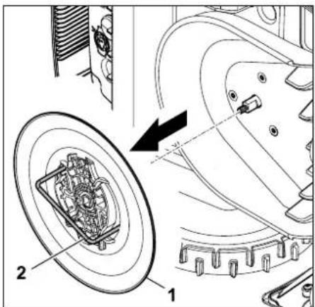
Support the machine with one hand. Remove the carrier plate (1) by pulling on the puller (2).
Installing the carrier plate:
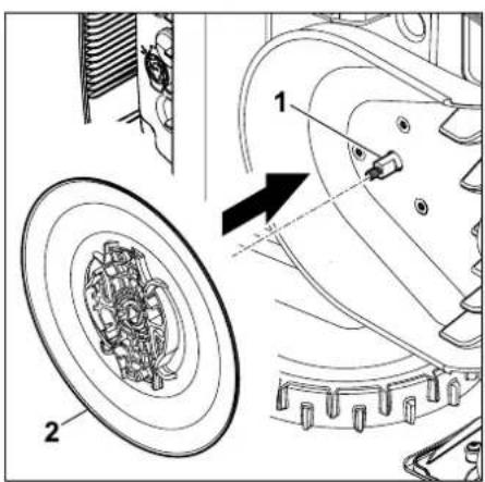
Thoroughly clean the blade shaft (1) and the mounting on the carrier plate (2). Push the carrier plate as far as possible onto the blade shaft.
• Install the mowing blade. ( 16.4)
16.7 Finding a wire break
In the event of a wire break, the red LED on the docking station flashes rapidly. ( 13.1) A corresponding message appears on the display of the robotic mower.
If a wire break cannot be found as described, contact your specialist dealer.
- Before finding the wire break, the button on the docking station must be pressed once (LED continues to flash rapidly).
- Remove the docking station cover and open the panel. ( 9.2)
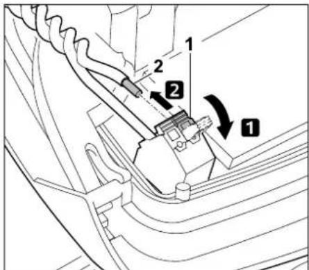
1 Fold open the left clamping lever (1).
2 Remove the wire end (2) from the terminal block and then close the clamping lever again.
- Open the panel and fit the docking station cover. ( 9.2)
The following instructions describe how to search for a wire break in a clockwise direction, i.e. the perimeter wire is followed in a clockwise direction starting at the docking station. If necessary, the search can also be carried out anti-clockwise, but in this case the right wire end must be removed from the terminal block.
- In the "Service" menu, select the "Find wire break" entry and confirm OK.
(⇒ 11.17)
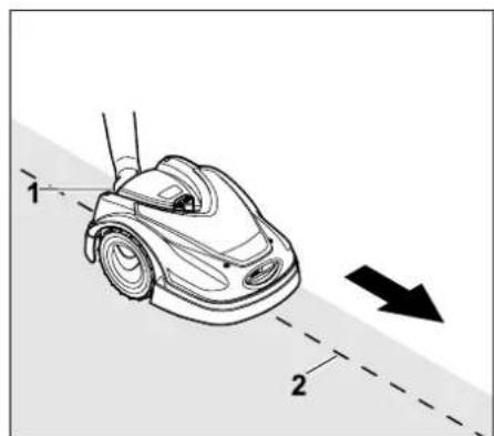
Starting at the docking station, follow the edge of the mowing area clockwise with the robotic mower. For this purpose, lift the machine slightly by the rear carrying handle (1) to relieve the weight on the drive wheels. Push the robotic mower, supported by its front wheels, and follow the perimeter wire (2). It must be ensured that the perimeter wire (2) runs under the wire sensors. The wire sensors are installed in a protected position on the left and right at the front of the robotic mower. During the wire break search, the signal strength is indicated on the display; the wire sensors are in the ideal position above the perimeter wire when this value is at its highest.
The Wire signal OK symbol appears on the display when the wire sensors are correctly receiving the wire signal.

In the area of the wire break, the signal strength drops and the Check wire signal symbol appears on the display.

- Bridge the break with the aid of a wire connector ( 12.16). If necessary, reroute the perimeter wire in the area of the break.
- Reconnect the left wire end. (⇒ 9.10)
- Once the wire break has been correctly rectified, the red LED illuminates.
(⇒ 13.1)
16.8 Storage and winter break
Note the following points when storing the robotic mower (e.g. winter break, temporary storage):
- Charge the battery (⇒ 15.7)
- Switch off automatic mowing (⇒ 11.5)
- Activate the highest safety level (⇔ 11.16)
• RMI 422 PC:
Activate ECO energy mode ( 11.11)
- Activate the disabling device (⇒ 5.2)
- Disconnect the power supply unit plug from the mains
- Carefully clean all external parts of the robotic mower and the docking station.
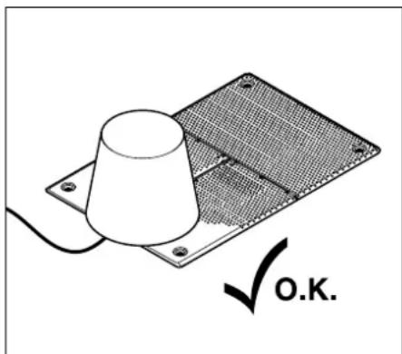
Cover the docking station with a suitable bucket, fasten the bucket.
- Store the robotic mower on its wheels in a dry, closed and dust-free room. Make sure that the machine is kept out of the reach of children.
- Always store the robotic mower in good operational condition.
- Keep all screws tightly fastened, replace danger signs and warnings on the machine that have become illegible, check the entire machine for wear and damage. Replace all worn or damaged parts.
- Any machine faults must be completely remedied prior to storage.

Never place or store objects on the robotic mower.
The temperature in the storage room should not fall below 5^ C.
Resuming operation of the robotic mower following storage for a long period:
The date and time may need to be corrected following storage for a long period. Appropriate selection windows are displayed during initial operation. If the selection windows are not automatically displayed, check the date and time in the "Settings" menu and correct if necessary. ( 11.11)
- Prepare the mowing area: Remove foreign objects and cut high grass short using a conventional lawn mower.
- Uncover the docking station and connect the power supply unit to the mains supply.
- Charge the battery (⇒ 15.7)
- Check the mowing plan and change as necessary. (⇒ 11.6)
- Switch on automatic mowing (⇒ 11.5)
- RMI 422 PC:
If necessary, activate Standard energy mode ( 11.11) and switch on GPS protection. ( 5.9)
16.9 Removing the docking station
The docking station can also be removed if the robotic mower is to be stored for long periods (e.g. winter break).
- Preparing the robotic mower for storage for a long period ( 16.8)
- Disconnect the power supply unit plug from the mains
- Remove the docking station cover and open the panel ( 9.2)
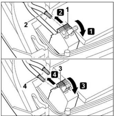
1 Fold open the left clamping lever (1).
2 Remove the left wire end (2) from the terminal block.
Close the clamping lever (1) again.
3 Fold open the right clamping lever (3).
4 Remove the right wire end (4) from the terminal block.
Close the clamping lever (3) again.
- Close the panel ( 9.2)
- Guide the left and right wire ends out of the docking station separately from each other
• Fit the docking station cover ( 9.2)
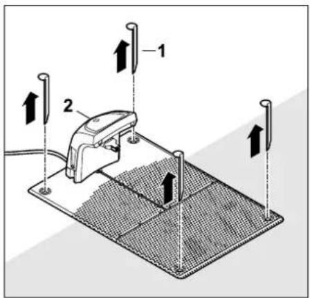
Pull out the pegs (1), remove the docking station (2) from the lawn with the power supply unit connected, clean thoroughly (with a moist cloth) and put into storage.
- Store the robotic mower together with the docking station and the power supply unit in the normal position and in a dry, closed and dust-free room. Dock the robotic mower in the docking station. Make sure that the machine is kept out of the reach of children.
- Protect the terminals of the perimeter wire from environmental influences (e.g. wrap with suitable insulating tape).
- Reinstall the docking station in the same way as during initial installation – in particular connect the right and left perimeter wire ends on the correct sides. (⇔ 9.8)
17. Standard spare parts
Mowing blade:
6301 702 0101
18. Accessories
- STIHL Kit S for mowing areas up to 500 m ^2
- STIHL Kit L for mowing areas from 2,000m^2 -4,000m^2
- Fixing pins STIHL AFN 075
- Perimeter wire STIHL ARB 501:
Length: 500 m
Diameter: 3,4 mm
– Wire connectors STIHL ADV 010
– Small-area module STIHL AKM 100
Additional accessories are available for the machine.
Further information is available from your STIHL specialist dealer, on the internet (www.stihl.com) or in the STIHL catalogue.

For safety reasons, only accessories approved by STIHL may be used with the machine.
19. Minimising wear and preventing damage
Important information on maintenance and care of the product group
robotic mower, battery powered (STIHL RMI)
STIHL assumes no liability for material or personal damage caused by the non-observance of information contained in the operating instructions, in particular with regard to safety, operation and maintenance, or which arise through the use of unauthorised attachment or spare parts.
Please always observe the following important information for the prevention of damage or excessive wear to your STIHL machine:
1. Wearing parts
Some parts of the STIHL machine are subject to normal wear even when used properly and must be replaced in due time depending on type and duration of use.
These include:
- Mowing blade
- Battery
The STIHL machine must be used, maintained and stored with the care described in this instruction manual. Any damage caused by non-compliance with the safety, operating and maintenance instructions is the sole responsibility of the user.
This applies in particular to:
- Incorrect handling of the battery (charging, storage)
– Incorrect electrical connection (voltage)
– Product modifications not approved by STIHL
– Use of tools or accessories which are not approved or suitable for the machine, or are of inferior quality
- Improper use of the product
– Use of the product for sporting or competitive events
- Resultant damage due to continued use of the product with defective components.
3. Maintenance operations
All operations listed in the section "Maintenance" must be performed regularly.
If these maintenance operations cannot be carried out by the user, a specialist dealer must be commissioned to perform them.
STIHL recommends that you have maintenance operations and repairs performed exclusively by a STIHL specialist dealer.
STIHL specialist dealers regularly attend training courses and are provided with technical information.
If these operations are neglected, faults may arise which are the responsibility of the user.
These include:
– damage to the machine as a result of inadequate or incorrect cleaning,
– corrosive and other resultant damage caused by incorrect storage,
– damage to the machine through the use of inferior-quality spare parts,
– damage due to untimely or inadequate maintenance or damage due to maintenance or repair work not performed in the workshops of specialist dealers.
20. Environmental protection
The machine, its packaging and accessories are all produced from recyclable materials and must be disposed of accordingly.
By disposing of materials separately, and in an environmentally friendly manner, valuable resources can be re-used. For this reason, the machine should be disposed of for recycling at the end of its useful life. Pay particular attention to the information in the "Disposal" section during disposal. ( 6.11)
Waste products such as batteries must always be disposed of properly. Observe local regulations.

Do not dispose of lithium-ion batteries with domestic waste. Please hand them in to a specialist dealer or at a hazardous waste collection
point.
20.1 Removing the battery
- Activate the disabling device. (⇒ 5.2)
- Open the flap. (⇒ 15.2)
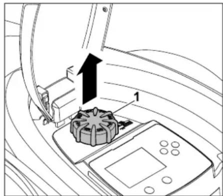
Remove the rotary knob (1) upwards.
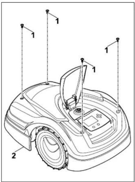
Remove the screws (1) from the cover (2). Remove the cover (2) upwards.
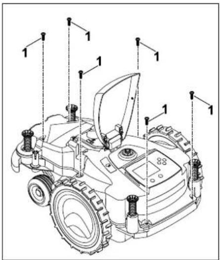
0478 131 9944 C - EN
Unscrew screws (1) and remove.
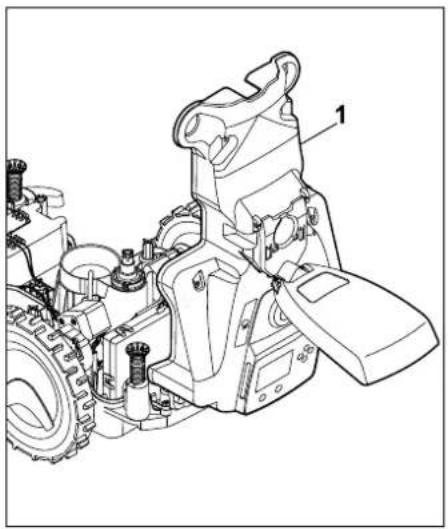
natural_image
Technical line drawing of a mechanical device with gears and housing (no text or symbols)
Fold the upper housing (1) rearwards.

Risk of injury!
Do not cut cables at the battery.
Risk of short circuit!
Always disconnect the cables and remove together with the battery.
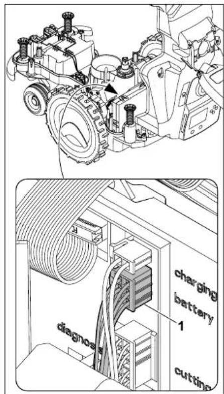
Detach the connector (1) (battery).
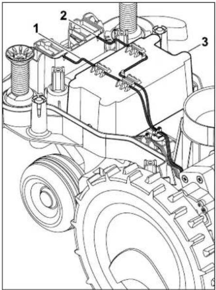
Remove cable (1) and cable (2) from the cable guides and remove the battery (3).

Risk of injury!
Prevent damage to the battery.
21. Transport

Risk of injury!
Before transporting, carefully read the section "For your safety" ( 6.), particularly the subsection
"Transporting the machine" ( 6.5), and follow all safety instructions – always activate the disabling device. ( 5.2)
21.1 Lifting or carrying the machine
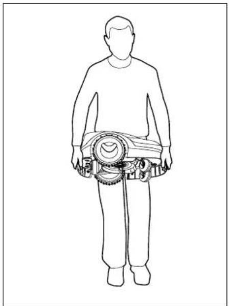
natural_image
Line drawing of a human figure standing with a circular device on the shoulder (no text or symbols)
Lift and carry the robotic mower at the front carry handle (1) and at the rear carry handle (2). Ensure that the mowing blade always faces away from your body and that there is sufficient distance between the mowing blade, particularly your feet and legs.
21.2 Securing the machine (lashing)
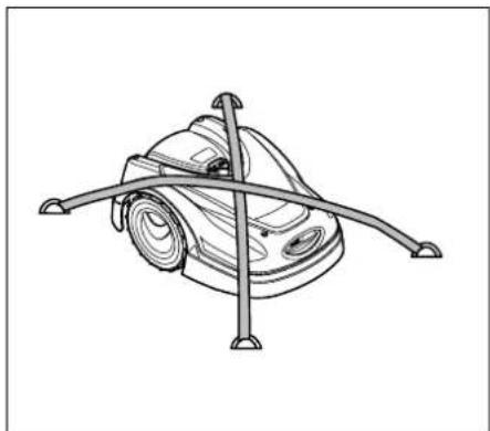
natural_image
Line drawing of a mechanical device with intersecting rods and a central hub (no text or symbols)
Secure the lawn mower on the load floor. Fasten the machine as illustrated using suitable fastening materials (straps, ropes) for this purpose.
Secure any other machine components being transported (e.g. docking station, small components) against slipping.
22.1 Robotic mower, automatic and cordless (RMI) with docking station (ADO)
STIHL Tirol GmbH
Hans Peter Stihl-Strasse 5
6336 Langkampfen
Austria
declares under our sole responsibility that
Design: Lawn mower,
automatic and battery-powered
Manufacturer's STIHL
brand:
Type: RMI 422.0
RMI 422.0 P
RMI 422.0 PC
Serial number: 6301
Design: Docking station
Manufacturer's brand: STIHL
Type: ADO 401
Firmware
V 1.02 - 1.07
Serial number: 6301
complies with the relevant provisions of Directives 2006/42/EC, 2011/65/EU, 2006/66/EC, 2014/53/EU and has been developed and manufactured in accordance with the versions of the following standards valid on the date of manufacture:
EN 50636-2-107, EN 60335-1 Ed 5, EN 55014-1, EN 55014-2, EN 61000-3-2, EN 61000-3-3
ETSI EN 301 489-1 V 2.2.0 (2017-03)
ETSI EN 301 489-3 V 2.2.1 (2017-03)
ETSI EN 303 447 V 1.1.1 (2017-09)
Additionally for RMI 422.0 PC:
ETSI EN 301 489-52 V 1.1.0 (2016-11)
The notified body TÜV Rheinland LGA Products GmbH, No. 0197, has reviewed the conformity according to Annex III Module B of the Directive 2014/53/EU and issued the following EU type examination certificate:
RT 60131603 0001
Storage of technical documentation:
STIHL Tirol GmbH
Product approval
The year of manufacture and machine number (serial number) are indicated on the machine.
Langkampfen, 02.01.2020
STIHL Tirol GmbH
p.p.
Matthias Fleischer, Research and Development Division Manager
p.p.
Sven Zimmermann, Quality Division Manager
23. Technical specifications
RMI 422.0, RMI 422.0 P, RMI 422.0 PC:
Serial number 6301
Mowing system Mulching mowing deck
Cutting utilities Cutter bar
RMI 422.0, RMI 422.0 P, RMI 422.0 PC:
Cutting width 20 cm
Speed of cutting
utilities 4450 rpm
Battery type Lithium-ion
Battery voltage U_DC 18,5 V
Cutting height 20 - 60 mm
Protection class III
Type of protection IPX4
In accordance with Directive 2006/42/EC and the EN 50636-2-107 standard:
Measured sound
power level L_WA 60 dB(A)
Uncertainty K_WA 2 dB(A)
L_WA + K_WA 62 dB(A)
Sound pressure level
L_pA 49 dB(A)
Uncertainty K_pA 2 dB(A)
Length 60 cm
Width 43 cm
Height 27 cm
RMI 422.0:
Power 60 W
Battery designation AAI 40
Battery power 42 Wh
Battery capacity 2,25 Ah
Weight 9 kg
RMI 422.0 P:
Power 60 W
Battery designation AAI 80
Battery power 83 Wh
Battery capacity 4,50 Ah
Weight 9 kg
RMI 422.0 PC:
Power 60 W
RMI 422.0 PC:
Battery designation AAI 80
Battery power 83 Wh
Battery capacity 4,50 Ah
Weight 10 kg
Mobile radio:
Supported frequency bands: E-GSM-900 and DCS-1800
Radiated maximum transmitting power:
E-GSM-900: 880 - 915 MHz:
33.0 dBm
DCS-1800: 1,710 -
1,785 MHz:
30.0 dBm
Docking station ADO 401:
Voltage U_DC 27 V
Protection class III
Type of protection IPX1
Weight 3 kg
Perimeter wire and guide loop:
Frequency range: 1.0 kHz - 90 kHz
Maximum field
strength: < 72 μA/m
Power supply unit:
OWA-60E-27
2,23 A
Mains voltage U_AC
100-240 V
Frequency 50/60 Hz
Direct current voltage
U_DC
27 V
Protection class II
Type of protection IP67
Transporting STIHL batteries:
STIHL batteries meet the requirements specified in UN manual
ST/SG/AC.10/11/Rev.5 Part III,
subsection 38.3.
The user may carry STIHL batteries to the place of use of the machine without further restrictions during road transport.
Country-specific legislation must be observed in the case of air or sea transport.
For further transport instructions, see http://www.stihl.com/safety-data-sheets
REACH:
REACH is an EC Directive for the registration, evaluation, authorisation and restriction of chemicals. For information on compliance with the REACH Directive (EC) No. 1907/2006, see www.stihl.com/reach
24. Messages
Messages provide information on active errors, faults and
recommendations. They are displayed in a dialog window and can be called up after pressing the OK button in the "Messages" menu. ( 11.9)
Recommendations and active messages also appear on the status screen. ( 11.2)
The message code, the time of occurrence, the priority and the frequency of occurrence can be called up in the message details.
- Recommendations are awarded the priority "Low" or "Info"; they appear in the status screen alternately with the text "iMow ready for op.". The robotic mower can still be operated, automatic operation continues.
- Faults are awarded the priority "Medium" and require action on the part of the user.
The robotic mower can only be operated again once the fault has been rectified.
- In the case of errors awarded the priority "High", the text "Contact your specialist dealer" appears on the display.
The robotic mower can only be operated again once the fault has been rectified by a STIHL specialist dealer.

If a message is still active despite the proposed remedial action, please contact your STIHL specialist dealer.
Faults that can only be rectified by a STIHL specialist dealer are not listed in the following. Should a fault of this kind occur, please communicate the 4-digit fault code and the fault text to your specialist dealer.

RMI 422 PC:
Messages that impair normal operation are also reported to the app. ( 10.)
The robotic mower enters standby after the message is sent and disables radio communication to preserve the battery.
Message:
0001 – Data updated
Press OK to release
Possible cause:
– The machine software has been updated
- Voltage loss
- Software or hardware error
Remedy:
- After the OK button is pressed, the robotic mower operates with the default settings - check and correct the settings (date, time, mowing plan)
Message:
0100 – Battery discharged
Charge battery
Possible cause:
– Battery voltage too low
Remedy:
- Place the robotic mower in the docking station to recharge the battery ( 15.7)
Message:
0180 - Temperature low
Temperature range not reached
Possible cause:
– Temperature inside the robotic mower too low
Remedy:
– Warm up the robotic mower
Message:
0181 – Temperature high
Temperature range exceeded
Possible cause:
– Temperature inside the robotic mower too high
Remedy:
- Allow the robotic mower to cool down
Message:
0183 – Temperature high
see message 0181
Message:
0185 - Temperature high
see message 0181
Message:
0186 - Temperature low
see message 0180
Message:
0187 – Temperature high
see message 0181
Message:
0302 – Drive motor fault
Temperature range exceeded
Possible cause:
– Temperature in left drive motor too high
Remedy:
- Allow the robotic mower to cool down
Message:
0305 - Drive motor fault
Left wheel is stuck
Possible cause:
- Overload at left drive wheel
Remedy:
– Clean the robotic mower (⇒ 16.2)
– Level out any uneven areas (holes, depressions) in the mowing area
Message:
0402 – Drive motor fault
Temperature range exceeded
Possible cause:
– Temperature in right drive motor too high
Remedy:
- Allow the robotic mower to cool down
Message:
0405 – Drive motor fault
Right wheel is stuck
Possible cause:
- Overload at right drive wheel
Remedy:
- Clean the robotic mower (⇒ 16.2)
– Level out any uneven areas (holes, depressions) in the mowing area
Message:
0502 - Mowing motor fault
Temperature range exceeded
Possible cause:
– Temperature in mowing motor too high
Remedy:
- Allow the robotic mower to cool down
Message:
0505 - Mowing motor fault
Mowing blade blocked
Possible cause:
– Dirt between carrier plate and mowing deck housing
- Mowing motor cannot be switched on
- Mowing motor overloaded
Remedy:
– Clean mowing blade and mowing deck
(⇒ 16.2)
Clean carrier plate (⇒ 16.6)
- Set higher cutting height ( 9.5)
– Level out any uneven areas (holes, depressions) in the mowing area
Message:
0703 – Battery discharged
see message 0100
Message:
0704 – Battery discharged
see message 0100
Message:
1000 – Rollover
Allowed inclination exceeded
Possible cause:
– Tilt sensor has detected a rollover
Remedy:
- Place the robotic mower on its wheels, check for damage and confirm the message with OK
Message:
1010 - iMow raised
Press OK to release
Possible cause:
– Robotic mower has been lifted by the hood
Remedy:
- Check movement of the hood and confirm the message with OK
Message:
1030 – Hood fault
Check hood
Then press OK
Possible cause:
- No hood detected
Remedy:
- Check hood (movement, firm seating) and confirm the message with OK
Message:
1105 - Flap open
Operation aborted
Possible cause:
- Flap open during automatic operation
- Flap open during automatic edge following
Remedy:
- Close the flap (⇒ 15.2)
Message:
1120 - Hood blocked
Check hood
Then press OK
Possible cause:
– Permanent collision detected
Remedy:
- Free the robotic mower, remove the obstacle or change routing of perimeter wire if necessary – then confirm the message with OK
- Check movement of the hood and confirm the message with OK
Message:
1125 – Remove obstacle
Check wire routing
Possible cause:
- Perimeter wire routed inaccurately
Remedy:
- Check the routing of the perimeter wire; check the clearances with the iMow Ruler ( 12.5)
Message:
1130 – Stuck
Free iMow
Then press OK
Possible cause:
– Robotic mower has become stuck
- Drive wheels are spinning
Remedy:
- Free the robotic mower, level out the mowing area or change routing of perimeter wire if necessary – then confirm the message with OK
- Clean the drive wheels, if necessary prevent operation during rain – then confirm the message with OK ( 11.12)
Message:
1131 – Stuck
On level surfaces:
Deactivate ASM
Possible cause:
- ASM also activated on a level surface
Remedy:
- Deactivate ASM on level surfaces
(⇒ 11.14)
Message:
1135 – Outside
Place iMow in mowing area
Possible cause:
- The robotic mower is located outside the mowing area
Remedy:
- Return the robotic mower to the mowing area
Message:
1140 - Too steep
Check wire routing
Possible cause:
- RMI 422:
Tilt sensor has detected a slope inclination exceeding 35%
- R M I 4 2 2 P :
Tilt sensor has detected a slope inclination exceeding 40%
Remedy:
- RMI 422:
Change routing of perimeter wire, block off lawns with slope inclinations exceeding 35%
- R M I 4 2 2 P :
Change routing of perimeter wire, block off lawns with slope inclinations exceeding 40%
Message:
1170 – No signal
Switch on docking station
Possible cause:
– Docking station is switched off
- No reception of wire signal during operation
- The robotic mower is located outside the mowing area
– Docking station or electronic components were replaced
Remedy:
- Switch on docking station and give mowing command
- Check power supply to the docking station
- Check LED on the docking station – the red LED must be permanently illuminated during operation ( 13.1)
- Return robotic mower to the mowing area
- Link robotic mower and docking station
(⇒ 11.16)
Message:
1180 - Dock iMow
Automatic docking
not possible
Possible cause:
– The docking station was not found
– The start or end of a corridor was installed incorrectly
Remedy:
- Check the LED on the docking station, switch on the docking station if necessary ( 13.1)
- Check docking ( 15.6)
- Check funnel-shaped entrance and exit areas of the corridor ( 12.11)
Message:
1190 - Docking error
Docking station occupied
Possible cause:
– Docking station occupied by a second robotic mower
Remedy:
– Dock the robotic mower once the docking station is unoccupied again
Message:
1200 – Mowing motor fault
see message 0505
Message:
1210 - Drive motor fault
Wheel stuck
Possible cause:
- Overload at a drive wheel
Remedy:
- Clean the robotic mower (⇒ 16.2)
– Level out any uneven areas (holes, depressions) in the mowing area
Message:
1220 - Rain detected
Mowing interrupted
Possible cause:
– Mowing operation has been interrupted or not started due to rain
Remedy:
- No action necessary; adjust rain sensor if required ( 11.12)
Message:
1230 - Docking error
Dock iMow
Possible cause:
– Docking station has been located, automatic docking not possible
Remedy:
- Check docking, if necessary manually dock robotic mower ( 15.6)
- Check perimeter wire – ensure correct routing in the area of the docking station ( 9.10)
Message:
2000 - Signal problem
Dock iMow
Possible cause:
– Wire signal faulty, fine tuning necessary
Remedy:
- Place the robotic mower in the docking station – then press OK
Message:
2010 – Replace mowing blade Allowed operating time reached
Possible cause:
- Mowing blade has been in use for more than 200 hours, replacement is necessary
Remedy:
- Replace the mowing blade, then confirm the blade replacement in the "Service" menu ( 16.4)
Message:
2020 – Recommendation
Annual service by spec. dealer required
Possible cause:
– Machine service recommended
Remedy:
– Have the annual service carried out by a STIHL specialist dealer
Message:
2030 – Battery
Allowed operating time reached
Possible cause:
– Battery replacement necessary
Remedy:
- Have the battery replaced by a STIHL specialist dealer
Message:
2031 – Charging failure
Check charging contacts
Possible cause:
- Charging cannot be started
Remedy:
- Check the charging contacts on the docking station and robotic mower and clean if necessary – then confirm the message with OK
Message:
2032 – Battery temperature
Outside temperature range
Possible cause:
– Temperature in battery during charging too low or too high
Remedy:
- Allow the robotic mower to warm up or cool down – observe permissible temperature range of battery
Message:
2040 – Battery temperature
Outside temperature range
Possible cause:
– Temperature in battery when starting mowing operation too low or too high
Remedy:
- Allow the robotic mower to warm up or cool down - observe permissible temperature range of battery ( 6.4)
Message:
2050 – Adapt mowing plan
Extend active times
Possible cause:
- Active times have been shortened/deleted or the mowing duration has been extended – the stored active times are insufficient for the necessary mowing operations.
Remedy:
- Extend the active times ( 11.7) or shorten the mowing duration ( 11.8)
Message:
2060 - Mowing completed
Press OK to release
Possible cause:
– Mowing in secondary area successfully completed
Remedy:
- Return the robotic mower to the mowing area and dock to charge the battery ( 15.6)
Message:
2070 - GPS signal
No reception at edge
Possible cause:
- The entire edge of the mowing area is in a dead spot
Remedy:
- Repeat edge following (⇒ 11.14)
- Contact a STIHL specialist dealer for a detailed diagnosis
Message:
2071 - GPS signal
No reception at starting pt. 1
Possible cause:
- Starting point 1 is in a dead spot
Remedy:
- Change the position of starting point 1
(⇒ 11.15)
Message:
2072 - GPS signal
No reception at starting pt. 2
Possible cause:
- Starting point 2 is in a dead spot
Remedy:
- Change the position of starting point 2
(⇒ 11.15)
Message:
2073 - GPS signal
No reception at starting pt. 3
Possible cause:
- Starting point 3 is in a dead spot
Remedy:
- Change the position of starting point 3
(⇒ 11.15)
Message:
2074-GPS signal
No reception at starting pt. 4
Possible cause:
- Starting point 4 is in a dead spot
Remedy:
- Change the position of starting point 4
(⇒ 11.15)
Message:
2075 - GPS signal
No reception in desired zone
Possible cause:
– The desired zone is in a dead spot
Remedy:
- Redefine the desired zone (⇒ 10.)
Message:
2076 - GPS signal
Desired zone not found
Possible cause:
- The desired zone could not be found during edge following
Remedy:
- Redefine the desired zone. Make sure that the desired zone and perimeter wire overlap ( 10.)
Message:
2077 – Desired zone
Desired zone outside home area
Possible cause:
- The desired zone is outside the stored home area
Remedy:
- Redefine the desired zone ( 10.)
Message:
2090 - Radio module
Contact your specialist dealer
Possible cause:
- Communication with the radio module interrupted
Remedy:
- No action required, firmware will be automatically updated if necessary
- Contact your STIHL specialist dealer if the problem persists
Message:
2100 - GPS protect.
Outside home area
Machine disabled
Possible cause:
– The robotic mower was removed from the home area
Remedy:
- Return the robotic mower to the home area and enter the PIN code ( 5.9)
Message:
2110 - GPS protect.
New location
New installation req.
Possible cause:
- The robotic mower was operated on a different mowing area. The wire signal of a second docking station is already stored.
Remedy:
- Perform new installation (⇒ 11.14)
Message:
2120 – Child lock
Child lock active
Possible cause:
– Impact sensor triggered several times consecutively
– Robotic mower has been lifted during travel
Remedy:
- No action required – if the impact sensor is not triggered again, the message automatically becomes inactive within max. 1 minute
- Deactivate the child lock (⇒ 11.16)
Message:
2400 – iMow successfully reset to factory default
Possible cause:
- Robotic mower has been reset to factory default
Remedy:
– Confirm message with OK
Message:
4001 - Internal fault
Outside temperature range
Possible cause:
– Temperature in battery or inside the machine too low or too high
Remedy:
- Allow the robotic mower to warm up or cool down - observe permissible temperature range of battery ( 6.4)
Message:
4002 – Rollover
see message 1000
Message:
4003 - Hood lifted
Check hood
Then press OK
Possible cause:
– Hood has been lifted
Remedy:
- Check the hood and confirm the message with OK
Message:
4004 - Internal fault
Press OK to release
Possible cause:
– Error in the programme sequence
– Power failure during automatic operation
- Robotic mower is located outside the mowing area
Remedy:
- Confirm message with OK
- Check power supply to the docking station – the red LED must be illuminated permanently during operation; then press the OK button ( 13.1)
- Return the robotic mower to the mowing area, then press the OK button
Message:
4005 – Internal fault
see message 4004
Message:
4006 - Internal fault
see message 4004
Message:
4027 - STOP button pressed
Press OK to release
Possible cause:
- STOP button has been pressed
Remedy:
– Confirm message with OK
25. Troubleshooting
Support and help on use
Support and help on use are available from a STIHL specialist dealer.
Contact options and further information can be found at https://support.stihl.com or https://www.stihl.com.
If necessary, contact a specialist dealer; STIHL recommends STIHL specialist dealers.
Fault:
The robotic mower operates at the wrong times.
Possible cause:
– Date and time incorrectly set
- Active times incorrectly set
– Machine has been operated by unauthorised persons
Remedy:
- Set the time and date ( 11.13)
- Set the active times (⇒ 11.6)
- Set the safety level to "Medium" or "High" (⇒ 11.16)
Fault:
The robotic mower fails to operate during an active time
Possible cause:
– Battery is charging
– Automatic mowing switched off
- Active time switched off
- Rain detected
– Weekly mowing duration has been reached, no further mowing operations required that week
- Message is active
- Flap open or not present
– Docking station not connected to power supply
- Outside allowed temperature range
- Power failure
Remedy:
- Allow the battery to finish charging
(⇒ 15.7)
- Switch on automatic mowing (⇒ 11.5)
- Release the active time ( 11.7)
- Set the rain sensor ( 11.12)
- No further action necessary, mowing operations are automatically distributed over the week – if necessary, start the mowing operation with the "Mowing" command ( 11.5)
- Rectify displayed fault and confirm the message with OK ( 24.)
- Close the flap ( 15.2)
- Check the power supply to the docking station ( 9.8)
- Allow the robotic mower to warm up or cool down – standard temperature range for operation of the robotic mower: +5°C to +40°C. Detailed information is available from your specialist dealer. ✕
- Check the power supply. When the robotic mower detects a wire signal again after a periodic check, it resumes the interrupted mowing operation. This means that it can take several minutes before mowing operation is automatically resumed following the power failure. The intervals between the individual periodic checks increase, the longer the power failure lasts.
Fault:
The robotic mower fails to mow after the commands "Start mowing" or "Start time-delayed mowing" have been called up
Possible cause:
- Insufficient battery charge
– Rain detected
- Flap not closed or not present
- Message active
– Homecall was activated on the docking station
Remedy:
- Charge the battery (⇒ 15.7)
- Set the rain sensor (⇒ 11.12)
- Close the flap (⇒ 15.2)
- Rectify the displayed fault and confirm the message with OK ( 24.)
- End Homecall or repeat command following docking
Fault:
The robotic mower is not working and nothing is shown in the display
Possible cause:
– Machine is in standby
- Battery defective
Remedy:
- Press any button to wake up the robotic mower – the status screen appears (⇔ 11.2)
- Replace the battery (✗)
Fault:
The robotic mower is noisy and vibrates
Possible cause:
– Mowing blade is damaged
- Mowing deck is very dirty
Remedy:
- Replace the mowing blade - remove any obstacles from the lawn (⇒ 16.4), (✗)
- Clean the mowing deck ( 16.2)
Fault:
Poor mulching or mowing result
Possible cause:
- Grass is too high in relation to the cutting height
– Lawn is extremely wet
- Mowing blade is blunt or worn
– Active times insufficient, mowing duration too short
– Size of mowing area set incorrectly
– Mowing area with very high grass
– Long periods of rain
Remedy:
- Adjust the cutting height ( 9.5)
- Set the rain sensor ( 11.12)
Change the active times ( 11.7)
- Replace the mowing blade (⇒ 16.4), (✗)
- Extend or add active times ( 11.7)
Extend the mowing duration ( 11.8)
- Create a new mowing plan ( 11.6)
- For neat mowing results, the robotic mower needs up to 2 weeks, depending on the size of the lawn.
- Allow mowing during rain ( 11.12)
Extend the active times ( 11.7)
Fault:
Display in a foreign language
Possible cause:
– Language setting has been changed
Remedy:
- Set the language (⇒ 11.11)
Fault:
Brown (earthy) patches appear in the mowing area
Possible cause:
- Mowing duration is too long in relation to the mowing area
- Perimeter wire has been routed with excessively tight radii
– Size of mowing area set incorrectly
- Reduce the mowing duration ( 11.8)
- Correct the routing of the perimeter wire
(⇒ 9.9)
- Create a new mowing plan ( 11.6)
Remedy:
Fault:
Mowing operations are significantly shorter than usual
Possible cause:
- Grass is very high or too wet
– Machine (mowing deck, drive wheels) is very dirty
– Battery has reached end of service life
Remedy:
- Adjust the cutting height ( 9.5)
Set the rain sensor ( 11.12)
Change the active times ( 11.7)
– Clean the machine ( 16.2)
- Replace the battery - observe corresponding recommendation in the display (✗), (⇒ 24.)
Fault:
The robotic mower is docked, the battery is not charging
Possible cause:
- The battery does not need to be charged
– Docking station not connected to power supply
- Incorrect docking
– Charging contacts corroded
- Machine is in standby
Remedy:
- No action necessary – battery charging occurs automatically below a certain voltage
- Check power supply to the docking station ( 9.8)
- Place the robotic mower in the mowing area and send it back to the docking station ( 11.5), check for correct docking – if necessary, correct the position of the docking station ( 9.1)
- Replace the charging contacts (✗)
- Press any button to wake up the robotic mower – the status screen appears ( 11.13)
Fault:
Docking not working
Possible cause:
– Uneven entry area to docking station
– Dirty drive wheels or dirty floor plate
- Perimeter wire incorrectly routed in area of docking station
- Ends of perimeter wire not cut
Remedy:
– Level out the entry area to the docking station ( 9.1)
- Clean the drive wheels and the floor plate of the docking station ( 16.2)
- Re-route the perimeter wire - ensure correct routing in the area of the docking station ( 9.9)
- Cut the perimeter wire as described and route it without excess length - do not roll up protruding ends ( 9.10)
Fault:
The robotic mower travels past the docking station or docks at an angle
Possible cause:
– Wire signal affected by
- Perimeter wire incorrectly routed in area of docking station
Remedy:
- Link the robotic mower and docking station again - ensure that the robotic mower is in correct alignment to the docking station ( 11.16)
- Re-route the perimeter wire - ensure correct routing in the area of the docking station ( 9.9)
Check for correct connection of the perimeter wire ends in the docking station ( 9.10)
Fault:
The robotic mower has crossed the perimeter wire
Possible cause:
- Perimeter wire incorrectly routed, clearances are not correct
– Slope inclination of mowing area too steep
– Interference affecting the robotic mower
Remedy:
- Check the routing of the perimeter wire ( 11.14); check the clearances with the iMow Ruler ( 12.5)
- Check the routing of the perimeter wire; block off areas with excessively steep slope inclinations ( 11.14)
- Contact your STIHL specialist dealer (✗)
Fault:
The robotic mower frequently becomes stuck
Possible cause:
– Cutting height too low
- Drive wheels dirty
– Depressions or obstacles in the mowing area
Remedy:
- Increase the cutting height (⇒ 9.5)
– Clean the drive wheels (⇒ 16.2)
- Fill up holes in the mowing area, install no-go areas around obstacles such as exposed roots, remove obstacles ( 9.9)
Fault:
The impact sensor is not activated when the robotic mower hits an obstacle
Possible cause:
– Low obstacle (height less than 8 cm)
- The obstacle is not firmly attached to the ground – e.g. fallen fruit or tennis ball
Remedy:
- Remove the obstacle or block it off with a no-go area ( 12.9)
- Remove the obstacle
Fault:
Driving tracks at edge of mowing area
Possible cause:
– Excessively frequent edge mowing
- Starting points in use
– Battery is charged very frequently towards the end of its service life
- Offset drive home (passage) not switched on
Remedy:
- Switch off edge mowing or reduce it to once per week ( 11.14)
- Start all mowing operations at the docking station in suitable mowing areas ( 11.15)
- Replace the battery – observe corresponding recommendation in the display (✗) (⇒ 24.)
- Switch on offset drive home (passage)
(⇒ 11.14)
Fault:
Unmown grass at edge of mowing area
Possible cause:
- Edge mowing switched off
- Perimeter wire routed inaccurately
- Grass is out of reach of mowing blade
Remedy:
- Mow the edge once or twice per week
(⇔ 11.14)
- Check the routing of the perimeter wire ( 11.14); check the clearances with the iMow Ruler ( 12.5)
– Cut the unmown areas regularly using a suitable grass trimmer
Fault:
No wire signal
Possible cause:
- Docking station switched off - LED does not illuminate
- Docking station not connected to mains supply – LED does not illuminate
- Perimeter wire not connected to the docking station - red LED flashes (⇒ 13.1)
- Break in perimeter wire - red LED flashes ( 13.1)
- Robotic mower and docking station are not linked
- Electronics fault - LED flashes SOS
(⇒ 13.1)
Remedy:
- Switch on the docking station (⇒ 13.1)
- Check the power supply to the docking station ( 9.8)
- Connect the perimeter wire to the docking station ( 9.10)
– Find the wire break ( 16.7), then repair the perimeter wire using wire connectors ( 12.16)
- Link the robotic mower and docking station ( 11.16)
- Contact your specialist dealer (✗)
Fault:
LED on the docking station flashes SOS
Possible cause:
– Minimum perimeter wire length not reached
- Electronics fault
Remedy:
- Install the accessory (AKM 100) (✗)
- Contact your specialist dealer (✗)
Fault:
The robotic mower is not receiving any GPS signal
Possible cause:
– The connection to the satellites is currently being established
- 3 or fewer satellites within range
– The machine is in a dead spot
Remedy:
- No further action required; it can take a few minutes for the connection to be established
- Avoid or remove obstacles that might be blocking the signal (e.g. trees, canopies)
Fault:
The robotic mower cannot establish a mobile radio connection
Possible cause:
– The mowing area is in a dead spot
– The radio module is not activated
Remedy:
- Have the radio module checked by a STIHL specialist dealer (✗)
Fault:
The robotic mower cannot be reached using the app
Possible cause:
- Radio module inactive
- The robotic mower is in standby mode
- No Internet connection
– The robotic mower is not associated with the correct e-mail address
Remedy:
- The radio module is switched off during linking, then it is reactivated and the robotic mower can be reached again
- Activate the robotic mower by pressing the button, set "Standard" energy mode ( 11.11)
- Connect the machine on which the app is installed to the Internet
- Correct the e-mail address ( 10.)
26. Service schedule
26.1 Handover confirmation
Model:
Serial number:

Date:

natural_image
Simple line drawing of a mechanical component with a cylindrical top and rectangular base (no text or symbols)
Next service
Date:

26.2 Service confirmation
Please hand this instruction manual to your STIHL specialist dealer in the case of maintenance operations.
He will confirm the service operations performed in the pre-printed boxes.

Service performed on

Next service date

- Installation examples
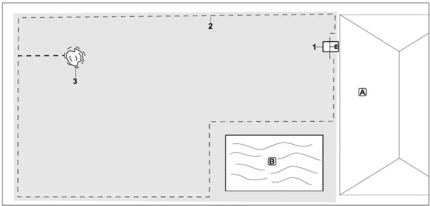
Rectangular mowing area with one tree and swimming pool
Docking station:
Location (1) directly next to the house A
No-go area:
Installation around the free-standing tree (3), based on a linking section installed at right angles to the edge.
Pool:
For safety reasons (specified wire clearance), the perimeter wire (2) is routed around the pool Ⓑ.
Wire clearances: ( 12.5)
Clearance to the edge: 28 cm
Clearance to adjoining area that can be travelled on (e.g. footpath) with a stepped
area height of less than +/- 1 cm: 0 c m
Clearance around the tree: 28 cm
Clearance to the pond: 100 cm
Programming:
No further adaptation is necessary following definition of the size of the mowing area.
Points to note:
Unmown areas around the swimming pool must be mown manually on a regular basis or cut using a suitable lawn trimmer.
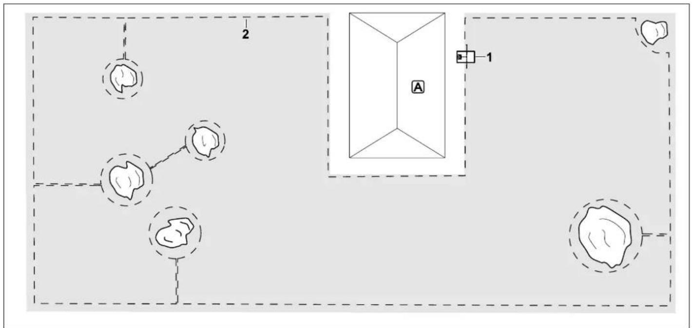
flowchart
graph TD
    A["Point A"] --> B["Point B"]
    B --> C["Point C"]
    C --> D["Point D"]
    D --> E["Point E"]
    E --> F["Point F"]
    F --> G["Point G"]
    G --> H["Point H"]
    H --> I["Point I"]
    I --> J["Point J"]
    J --> K["Point K"]
    K --> L["Point L"]
    L --> M["Point M"]
    M --> N["Point N"]
    N --> O["Point O"]
    O --> P["Point P"]
    P --> Q["Point Q"]
    Q --> R["Point R"]
    R --> S["Point S"]
    S --> T["Point T"]
    T --> U["Point U"]
    U --> V["Point V"]
    V --> W["Point W"]
    W --> X["Point X"]
    X --> Y["Point Y"]
    Y --> Z["Point Z"]
U-shaped mowing area with several free-standing trees
Docking station:
Location (1) directly next to the house A
No-go areas:
Installation around the free-standing trees, based on linking sections installed at right angles to the edge (2), two no-go areas are connected via a linking section.
Wire clearances: ( 12.5)
Clearance to the edge: 28 cm
Clearance to adjoining area that can be travelled on (e.g. footpath) with a stepped area height of less than +/- 1 cm: 0 c m Clearance around the trees: 28 cm
Programming:
No further adaptation is necessary following definition of the size of the mowing area.
Points to note:
Tree in the corner of the mowing area – mow the area behind the blocked-off tree regularly using a suitable lawn trimmer or leave as a patch of high grass.
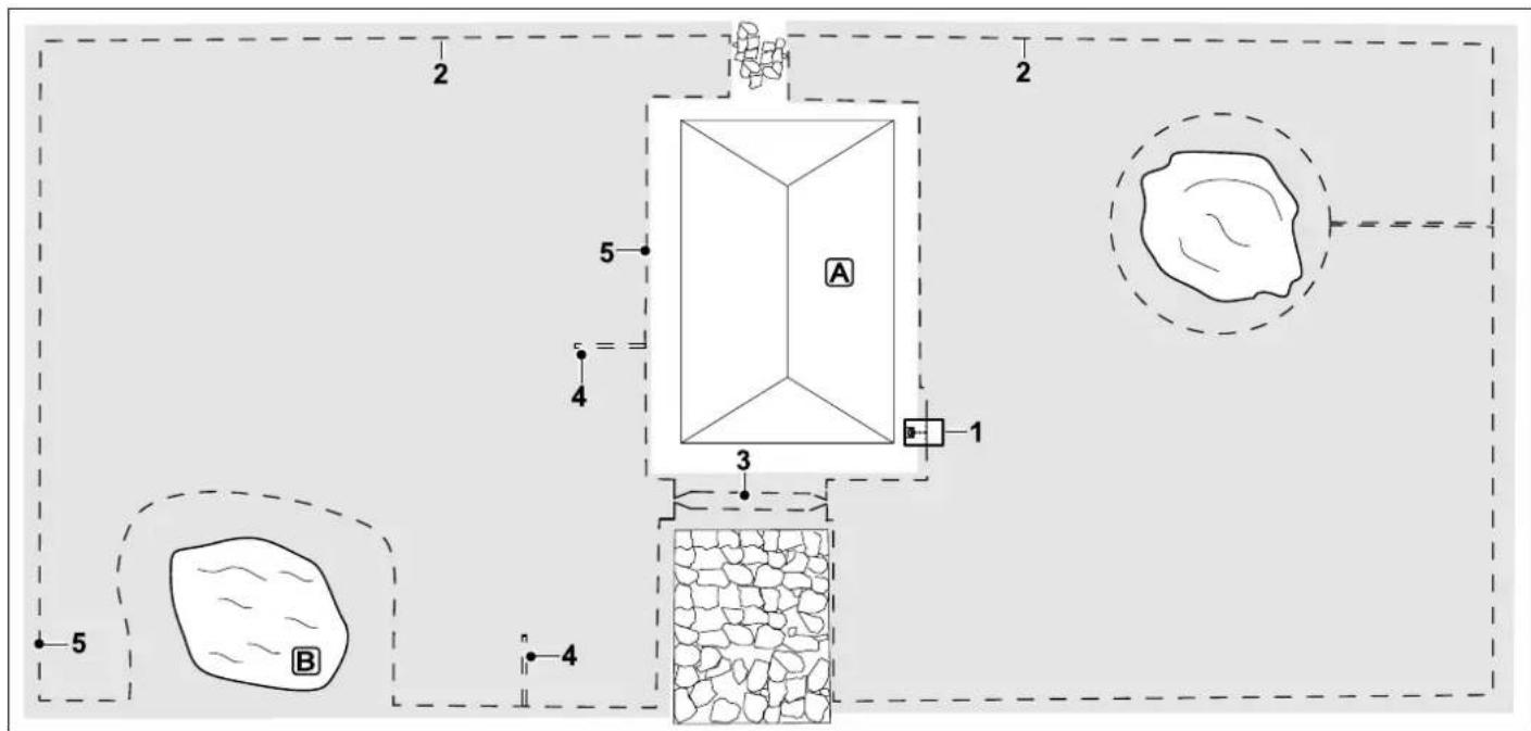
Divided mowing area with a pond and a free-standing tree
Docking station:
Location (1) directly next to the house Ⓐ
No-go area:
Installation around the free-standing tree, based on a linking section installed at right angles to the edge.
Pond:
For safety reasons (specified wire clearance), the perimeter wire (2) is routed around the pond Ⓑ.
Wire clearances: (→ 12.5)
Clearance to the edge: 28 cm
Clearance to adjoining area that can be travelled on (e.g. footpath) with a stepped
area height of less than +/- 1 cm: 0 c m
Around the tree: 28 cm
Clearance to the pond: 100 cm
Corridor:
Installation of a corridor (3). Wire clearance: 22 cm ( 12.11)
Guide loops:
Installation of two guide loops (4) for using the offset drive home function.(⇔ 11.14)
Minimum clearance from the corridor entrance: 2 m
Note the minimum clearance to corners.
(⇒ 12.12)
Programming:
Define the total size of the mowing area, program two starting points (5) (close to the docking station and in the contorted corner near the pond) ( 11.15)
Points to note:
Unmown areas, e.g. around the pond must be mown manually on a regular basis or cut using a suitable lawn trimmer.
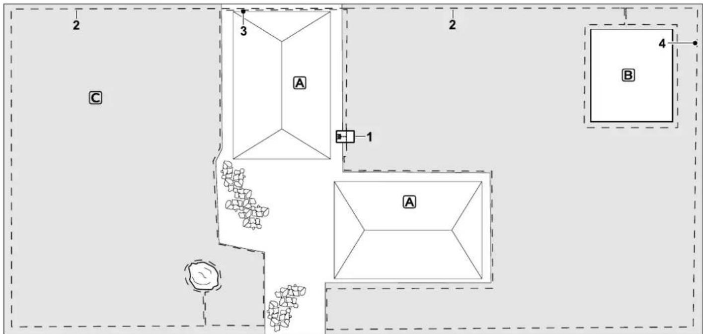
Divided mowing area – the robotic mower cannot travel independently from one mowing area to the other.
Docking station:
Location (1) directly next to the houses A
No-go areas:
Installation around the free-standing tree and around the vegetable patch based on a linking section installed at right angles to the edge.
Wire clearances: ( 12.5)
Clearance to adjoining area that can be travelled on (e.g. patio) with a stepped area height of less than +/- 1 cm: 0 cm Clearance to high obstacles: 28 cm
Clearance to the tree: 28 cm
Minimum wire clearance in the confined areas behind the vegetable patch: 100 cm
Secondary area:
Installation of a secondary area C, linking section (3) on the patio accommodated in a cable duct.
Programming:
Define the size of the mowing area (without secondary area), program one starting point (4) in the confined area for using the offset drive home function ( 11.14) – starting frequency 2 of 10 operations ( 11.15)
Points to note:
Bring the robotic mower to the secondary area several times per week and activate the command "Start mowing". (⇒ 11.5)
Take the mowing performance into account. ( 14.4)
If necessary, install two separate mowing areas with 2 docking stations.
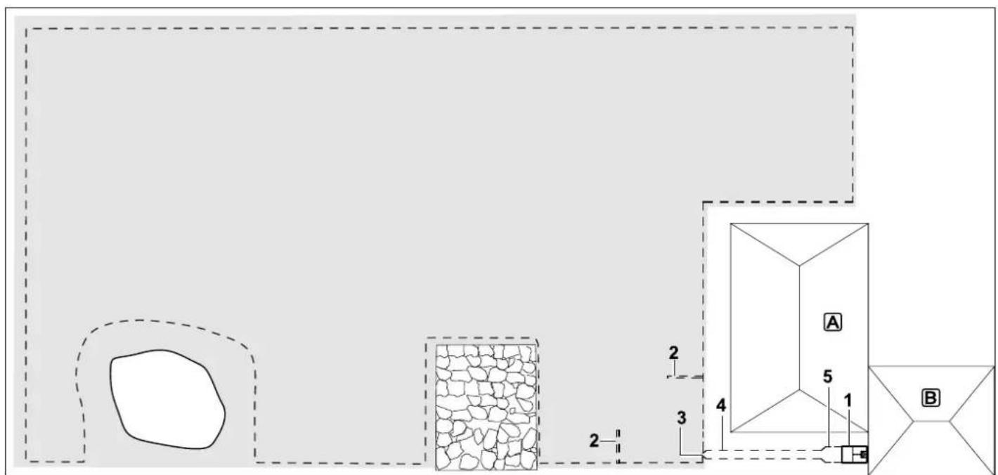
Mowing area with external docking station (1)
Docking station:
Location (1) next to the garage B and behind the house A.
Wire clearances: ( 12.5)
Clearance to the edge: 28 cm
Clearance to adjoining area that can be travelled on (e.g. patio) with a stepped area height of less than +/- 1 cm: 0 c m Clearance to the pond: 100 cm
Guide loops:
Installation of two guide loops (2) for using the offset drive home function. ( 11.14)
Minimum distance from the corridor entrance: 2 m
Note the minimum clearance to corners.
(⇒ 12.12)
Programming:
Define the size of the mowing area and program at least one starting point outside the corridor to the docking station.(⇒ 11.15)
Points to note:
Installation of a corridor (4) with funnel-shaped entrance area (3). ( 12.11)
Wire clearance: 22 cm
The corridor (4) leads to the external docking station (1). Increase the wire clearance in the corridor to the width of the ground plate (5) one metre in front of the docking station. ( 9.9)
Note the space requirement in the corridor and beside the docking station.
Chère cliente, cher client,
RMI 422 P, RMI 422 PC :
Avertissement !
natural_image
Line drawing of a hand operating a mechanical device with arrows indicating motion (no text or symbols)
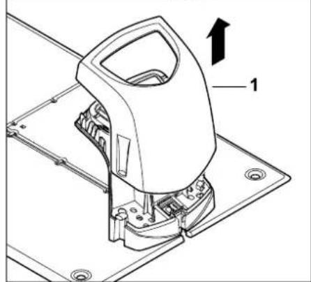
natural_image
Technical line drawing of a mechanical device with labeled component '1' and directional arrow (no text or symbols beyond label)
natural_image
Technical diagram of a mechanical component with an arrow indicating direction (no text or symbols present)
natural_image
Technical line drawing of a mechanical assembly with labeled component '1' (no text or symbols beyond label)
natural_image
Technical line drawing of three mechanical components: a spool, a pin-like tool, and a connector (no text or symbols)
OK
natural_image
Technical line drawing of a mechanical device with labeled parts (1 and 2), no readable text or symbols present.
natural_image
Diagram of a cell with a labeled arrow pointing to a nucleus (no text or symbols present)
- Activer/Désactiver commande
automatique :
Quand la commande
natural_image
Technical line drawing of a mechanical component with no visible text or symbols
natural_image
Technical line drawing of a mechanical assembly with labeled component 'F' (no text or symbols beyond label)
natural_image
Technical line drawing of a mechanical assembly with labeled component (no text or symbols present)
natural_image
Line drawing of a human figure holding a mechanical device (no text or symbols)
natural_image
Line drawing of a vacuum cleaner with four blades, no text or symbols present
Station base occupée
Causes possibles :
natural_image
Simple line drawing of a mechanical component with a cylindrical top and rectangular base (no text or symbols)
Prochain entretien
Date: ____ ____ ____ ____ ____
RMI 422 P, RMI 422 PC:
Waarschuwing!
natural_image
Line drawing of a hand holding a small object with arrows indicating motion or assembly (no text or symbols)
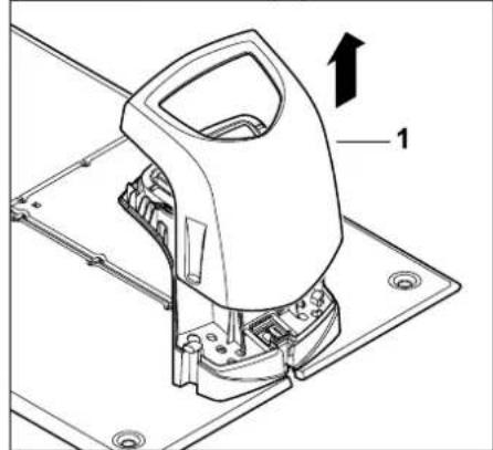
natural_image
Technical diagram of a mechanical assembly with labeled component 1 (no text or symbols beyond label)
natural_image
Technical diagram of a mechanical component with an arrow indicating direction (no text or symbols present)
natural_image
Technical line drawing of a mechanical assembly with labeled component '1' (no text or symbols beyond label)
natural_image
Technical line drawing of three mechanical components: a spool, a pin-like tool, and a connector (no text or symbols present)
natural_image
Technical line drawing of a mechanical component with labeled parts (no text or symbols present)
natural_image
Technical line drawing of a mechanical device with labeled parts (1 and 2), no readable text or symbols present.
natural_image
Diagram of a cell with a labeled arrow pointing to a nucleus (no text or symbols present)
5. Status Radiogr. module (RMI 422 PC):

Informatie over de radiografische module
11. Energiemodus (RMI 422 PC):
2. ASM (anti-stuck-manoeuvre):
3. GPS-beveiliging (RMI 422 PC):
natural_image
Technical line drawing of a mechanical component with no visible text or symbols
natural_image
Technical line drawing of a mechanical assembly with labeled component 'F' (no text or symbols beyond label)
1 Klap de linker klemhendel (1) omhoog.
natural_image
Diagram of a mechanical device with a labeled component (1) and an upward arrow, no readable text or symbols present.
natural_image
Technical line drawing of a mechanical device with labeled component (no text or symbols present)
Trek de kabelstekker (1) (accu) los.
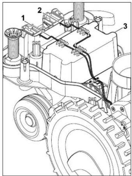
natural_image
Line drawing of a human figure holding a mechanical device (no text or symbols)
natural_image
Line drawing of a mechanical device with intersecting rods and a central body (no text or symbols)
Type: Dockingstation
Merk: STIHL
Type: ADO 401
Firmware V 1.02 - 1.07
RMI 422.0, RMI 422.0 P, RMI 422.0 PC:
Serienummer 6301
Maaisysteem Mulchmaaiwerk
RMI 422.0, RMI 422.0 P, RMI 422.0 PC:
Accutype Lithium-ion
Accuspanning U_DC 18,5 V
- Storing in programmaverloop
natural_image
Simple line drawing of a mechanical component with a cylindrical top and rectangular base (no text or symbols)
Smontaggio docking station 425
Ricambi standard 426
Accessori 426
RMI 422 P, RMI 422 PC:
natural_image
Simple line drawing of a microscope with an X mark, no text or symbols present
Docking station interna:
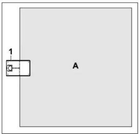
Docking station esterna:
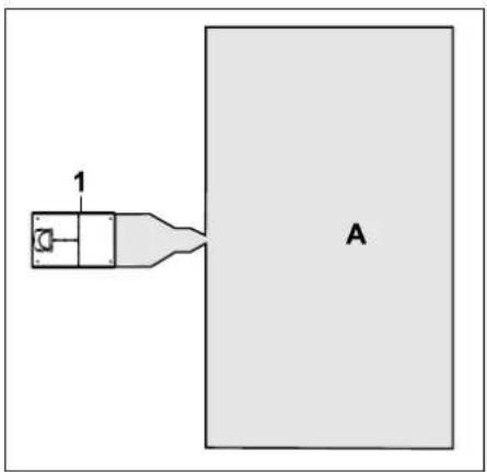
natural_image
Technical diagram of a car interior showing engine compartment and fan assembly (no text or labels)
natural_image
Technical line drawing of a mechanical assembly with labeled component '1' (no text or symbols beyond label)
natural_image
Technical line drawings of three mechanical components: a spool, a tool, and a connector (no text or symbols present)
Filo perimetrale con docking station interna:
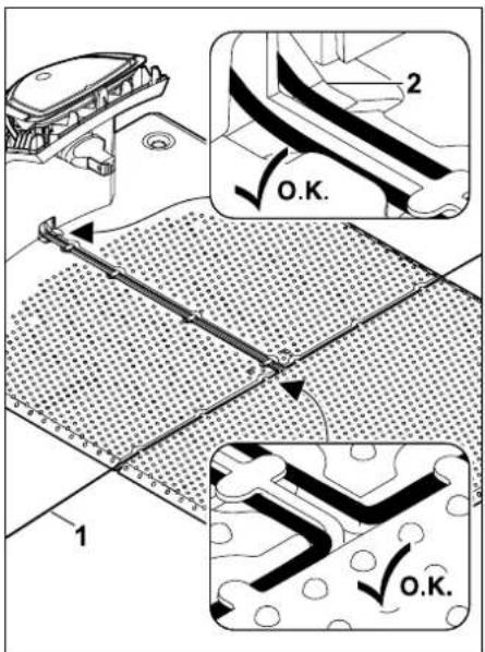
natural_image
Technical line drawing of a mechanical assembly with labeled components (no readable text or symbols)
natural_image
Diagram of a cell with a labeled arrow pointing to a nucleus, surrounded by curved lines (no text or symbols)
Segnale filo OK:
5. Stato modulo radio (RMI 422 PC):
natural_image
Technical line drawing of a mechanical component with no visible text or symbols
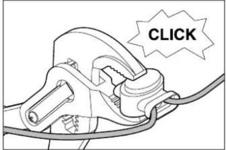
natural_image
Simple black battery icon on white background, no text or symbols present
natural_image
Technical line drawing of a mechanical assembly with labeled component 'F' (no text or symbols beyond label)
16.9 Smontaggio docking station
Estrarre verso l'alto la manopola (1).
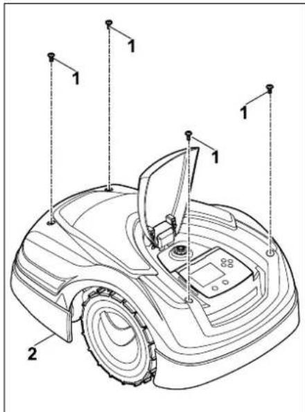
natural_image
Technical line drawing of a camera assembly with labeled component (no text or symbols present)
natural_image
Line drawing of a human figure holding a mechanical device (no text or symbols)
natural_image
Line drawing of a mechanical device with intersecting rods and a central body (no text or symbols)
RMI 422.0, RMI 422.0 P, RMI 422.0 PC:
RMI 422.0, RMI 422.0 P, RMI 422.0 PC:
Docking station ADO 401:
Tensione U_CC 27 V
frequenza: 1,0 kHz - 90 kHz
Docking station occupata
Possibile causa:
natural_image
Simple line drawing of a mechanical component with a cylindrical top and rectangular base (no text or symbols)
Prossima revisione
Data:
natural_image
Exterior view of a modern robotic car (no visible text or symbols)
C
EUR 1

0478 131 9944 C