
286A - Receiver DBX - Free user manual and instructions
Find the device manual for free 286A DBX in PDF.
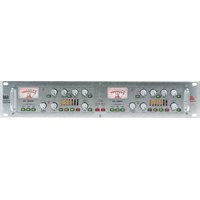
| Product Type | Microphone Preamp/Processor |
| Brand | DBX |
| Model | 286A |
| Power Supply | 15 W, 120 VAC 60 Hz (USA) / 100 VAC 50/60 Hz |
| Dimensions | 1U rack 19 inches (44.5 mm height) |
| Inputs | Microphone XLR balanced/unbalanced, Line 6.35 mm Jack balanced/unbalanced |
| Outputs | Line 6.35 mm Jack unbalanced |
| Main Functions | Microphone preamp with gain +10 to +60 dB, compressor, de-esser, enhancer, expander/gate, bypass, high-pass filter 80 Hz (18 dB/octave), +48 V phantom power, insert loop |
| Microphone Gain | +10 dB to +60 dB |
| Line Gain | -20 dB to +30 dB |
| Line Input Impedance | > 720 kΩ |
| Output Impedance | 47 Ω |
| Maximum Output Level | +21 dBu |
| High-Pass Filter | 80 Hz, 18 dB/octave |
| Phantom Power | +48 V (switchable) |
| Noise Reduction | Expander/gate with adjustable threshold and ratio |
| Safety | CE compliant, EN 60065, EN 55013, EN 55020; electric shock warning, do not open |
| Maintenance and Cleaning | Clean with a dry, soft cloth. Avoid any liquid. Disconnect before cleaning. |
| Spare Parts and Repairability | Externally accessible fuse, replace with same type and rating. No internal user-serviceable parts. Refer to qualified technician. |
| General Information | Complies with directives 73/23/EEC and 89/336/EEC as amended by 93/68/EEC. Manufactured by dbx Professional Products. |
Frequently Asked Questions - 286A DBX
User questions about 286A DBX
0 question about this device. Answer the ones you know or ask your own.
Ask a new question about this device
Download the instructions for your Receiver in PDF format for free! Find your manual 286A - DBX and take your electronic device back in hand. On this page are published all the documents necessary for the use of your device. 286A by DBX.
USER MANUAL 286A DBX
Owner/Operator Manual
WARNING: TO REDUCE THE RISK OF FIRE OR ELECTRIC SHOCK DO NOT EXPOSE THIS EQUIPMENT TO RAIN OR MOISTURE
The symbols shown above are internationally accepted symbols that warn of potential hazards with electrical products. The lightning flash with arrowpoint in an equilateral triangle means that there are dangerous voltages present within the unit. The exclamation point in an equilateral triangle indicates that it is necessary for the user to refer to the owner's manual.
These symbols warn that there are no user serviceable parts inside the unit. Do not open the unit. Do not attempt to service the unit yourself. Refer all servicing to qualified personnel. Opening the chassis for any reason will void the manufacturer's warranty. Do not get the unit wet. If liquid is spilled on the unit, shut it off immediately and take it to a dealer for service. Disconnect the unit during storms to prevent damage.
U.K. MAINS PLUG WARNING
A moulded mains plug that has been cut off from the cord is unsafe. Discard the mains plug at a suitable disposal facility. NEVER UNDER ANY CIRCUM-
STANCES SHOULD YOU INSERT A DAMAGED OR CUT MAINS PLUG INTO
A 13 AMP POWER SOCKET. Do not use the mains plug without the fuse cover in place. Replacement fuse covers can be obtained from your local retailer.
Replacement fuses are 13 amps and MUST be ASTA approved to BS1362.
WARNING
FOR YOUR PROTECTION, READ THESE INSTRUCTIONS:
WATER AND MOISTURE: Appliance should not be used near water (e.g. near a bathtub, washbowl, kitchen sink, laundry tub, in a wet basement, or near a swimming pool, etc). Care should be taken so that objects do not fall and liquids are not spilled into the enclosure through openings.
POWER SOURCES: The appliance should be connected to a power supply only of the type described in the operating instructions or as marked on the appliance.
GROUNDING OR POLARIZATION: Precautions should be taken so that the grounding or polarization means of an appliance is not defeated.
POWER CORD PROTECTION: Power supply cords should be routed so that they are not likely to be walked on or pinched by items placed upon or against them, paying particular attention to cords at plugs, convenience receptacles, and the point where they exit from the appliance.
SERVICING: To reduce the risk of fire or electric shock, the user should not attempt to service the appliance beyond that described in the operating instructions. All other servicing should be referred to qualified service personnel.
FOR UNITS EQUIPPED WITH EXTERNALLY ACCESSIBLE FUSE RECEPTACLE: Replace fuse with same type and rating only.
MULTIPLE-INPUT VOLTAGE: This equipment may require the use of a different line cord, attachment plug, or both, depending on the available power source at installation. Connect this equipment only to the power source indicated on the equipment rear panel. To reduce the risk of fire or electric shock, refer servicing to qualified service personnel or equivalent.
ELECTROMAGNETIC COMPATIBILITY
This unit conforms to the Product Specifications noted on the Declaration of
Conformity. Operation is subject to the following two conditions:
- this device may not cause harmful interference, and
- this device must accept any interference received, including interference that may cause undesired operation.
Operation of this unit within significant electromagnetic fields should be avoided.
- use only shielded interconnecting cables.
SAFETY INSTRUCTIONS
NOTICE FOR CUSTOMERS IF YOUR UNIT IS EQUIPPED WITH A POWER CORD.
WARNING: THIS APPLIANCE MUST BE EARTHED.
The cores in the mains lead are coloured in accordance with the following code:
GREEN and YELLOW - Earth
BLUE - Neutral
BROWN - Live
As colours of the cores in the mains lead of this appliance may not correspond with the coloured markings identifying the terminals in your plug, proceed as follows:
- The core which is coloured green and yellow must be connected to the terminal in the plug marked with the letter E, or with the earth symbol, or coloured green, or green and yellow.
- The core which is coloured blue must be connected to the terminal marked N or coloured black.
- The core which is coloured brown must be connected to the terminal marked L or coloured red.
This equipment may require the use of a different line cord, attachment plug, or both, depending on the available power source at installation. If the attachment plug needs to be changed, refer servicing to qualified service personnel who should refer to the table below. The green/yellow wire shall be connected directly to the unit's chassis.
| CONDUCTOR | WIRE COLOR | ||
| Normal Alt | |||
| L | LIVE | BROWN | BLACK |
| N | NEUTRAL | BLUE | WHITE |
| E | EARTH GND | GREEN/YEL | GREEN |
WARNING: If the ground is defeated, certain fault conditions in the unit or in the system to which it is connected can result in full line voltage between chassis and earth ground. Severe injury or death can then result if the chassis and earth ground are touched simultaneously.
DECLARATION OF CONFORMITY
Manufacturer's Name: dbx Professional Products
Manufacturer's Address: 8760 S. Sandy Parkway
Sandy, Utah 84070, USA
declares that the product: dbx 286A
conforms to the following Product Specifications:
Safety: EN 60065 (1993)
IEC65 (1985) with Amendments 1, 2, 3
EMC: EN 55013 (1990)
EN 55020 (1991)
Supplementary Information:
The product herewith complies with the requirements of the Low Voltage Directive 73/23/EEC and the EMC Directive 89/336/EEC as amended by Directive 93/68/EEC.
dbx Professional Products
President of dbx
8760 S. Sandy Parkway
Sandy, Utah 84070, USA
June 23, 2003
European Contact: Your Local dbx Sales and Service Office or
MANUAL CONTENTS
ENGLISH 2
FRANÇAIS 15
DEUTSCH 29
ESPAÑOL 47
ENGLISH CONTENTS
INTRODUCTION 2
USING THE FOUR PROCESSORS IN DIFFERENT COMBINATIONS .....9
SUGGESTED SETTINGS/USAGES 10
EXPANDER/GATE 10
COMPRESSOR 11
ENHANCER 11
PROBLEMS, POSSIBLE CAUSES, SOLUTIONS ....11
NOISE/HISS BUILDUP 11
AUDIBLE DISTORTION, ETC. 12
SOUND CUTTING OFF 12
LISPY VOCALS 12
SHRILLNESS/ EXCESSIVE BRIGHTNESS ....12
LOW RUMBLE/EXCESSIVE LOW FREQUENCIES ....12
No Gain Reduction Meter Activity When in Compression Mode .....12
TECHNICAL SUPPORT/FACTORY SERVICE 13
REGISTRATION CARD/USER FEEDBACK 13
WARRANTY 13
BLOCK DIAGRAM 63
SPECIFICATIONS 64
Congratulations on choosing the dbx 286A Mic Preamp/Processor. The 286A is a powerful, user-friendly unit, providing concise and intuitive controls for all your mic processing needs, whether you use a microphone to record vocals and acoustic instruments, sample acoustic sounds, or for a public address system installation. The 286A is also capable of providing effective processing for electronic instruments, individual mixer tracks, and other mono sound sources.
You can think of the 286A as two separate processors, a Mic Preamp Section and a Processing Section. These two sections can be used together, or the 286A can be used as a dedicated Mic Preamp by defeating the Processing Section via the front panel BYPASS switch. Furthermore, the Processing Section provides four specific types of processing: Compression, De-essing, Enhancement and Expansion/Gating. These four controls can be used in any combination, as appropriate to your requirements. External audio processors (e.g., equalizer, delay unit, etc.), can be placed in the signal chain directly between the Mic Preamp Section and remaining 286A processing via the rear panel INSERT jack. We recommend that you take a moment and read through the 286A manual to better understand the power of the 286A's processing, and how you can use the 286A to its fullest potential.
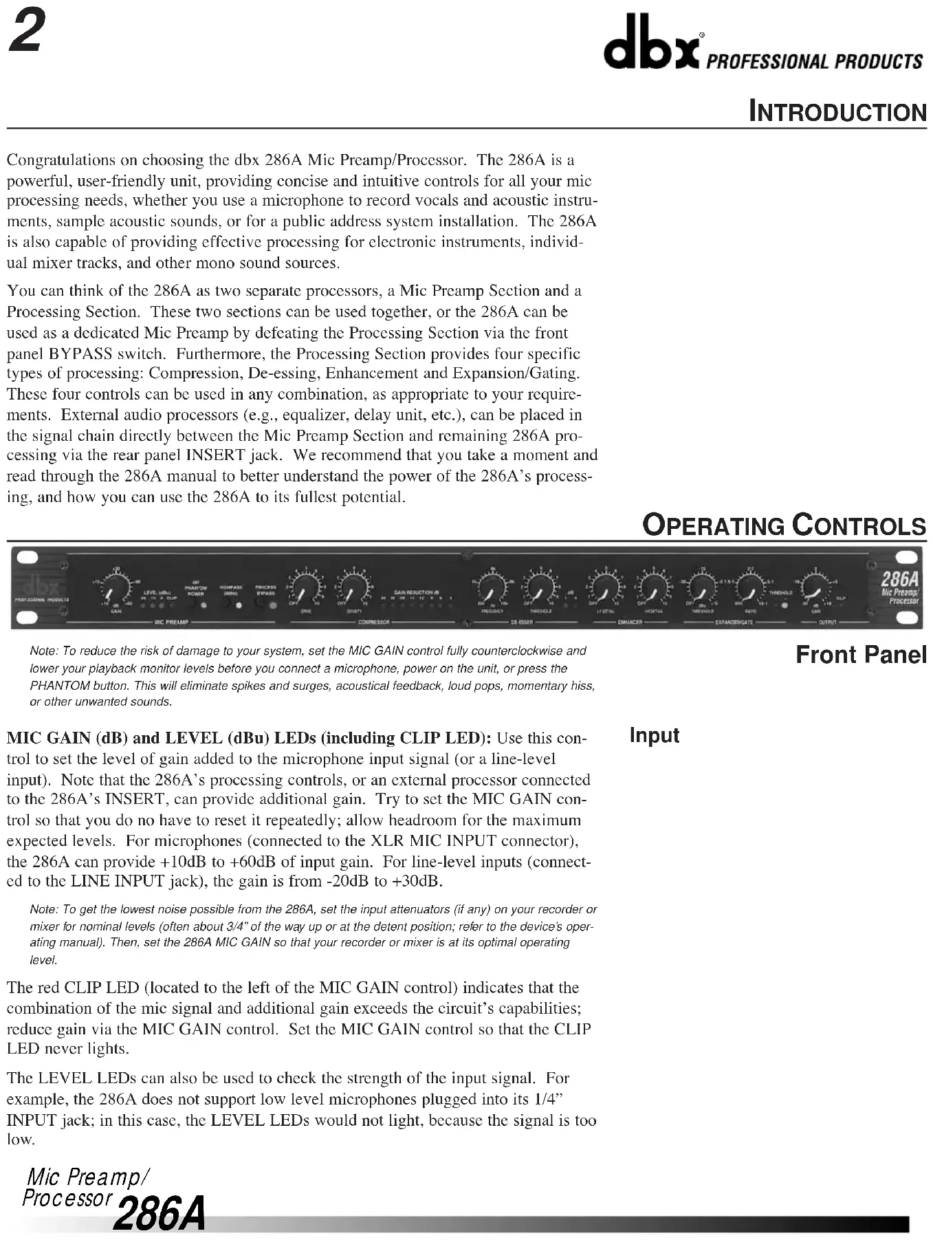
OPERATING CONTROLS

Note: To reduce the risk of damage to your system, set the MIC GAIN control fully counterclockwise and lower your playback monitor levels before you connect a microphone, power on the unit, or press the PHANTOM button. This will eliminate spikes and surges, acoustical feedback, loud pops, momentary hiss, or other unwanted sounds.
Front Panel
MIC GAIN (dB) and LEVEL (dBu) LEDs (including CLIP LED): Use this control to set the level of gain added to the microphone input signal (or a line-level input). Note that the 286A's processing controls, or an external processor connected to the 286A's INSERT, can provide additional gain. Try to set the MIC GAIN control so that you do no have to reset it repeatedly; allow headroom for the maximum expected levels. For microphones (connected to the XLR MIC INPUT connector), the 286A can provide +10dB to +60dB of input gain. For line-level inputs (connected to the LINE INPUT jack), the gain is from -20dB to +30dB.
Note: To get the lowest noise possible from the 286A, set the input attenuators (if any) on your recorder or mixer for nominal levels (often about 3/4" of the way up or at the detent position; refer to the device's operating manual). Then, set the 286A MIC GAIN so that your recorder or mixer is at its optimal operating level.
The red CLIP LED (located to the left of the MIC GAIN control) indicates that the combination of the mic signal and additional gain exceeds the circuit's capabilities; reduce gain via the MIC GAIN control. Set the MIC GAIN control so that the CLIP LED never lights.
The LEVEL LEDs can also be used to check the strength of the input signal. For example, the 286A does not support low level microphones plugged into its 1/4" INPUT jack; in this case, the LEVEL LEDs would not light, because the signal is too low.
Input
PHANTOM POWER Button and LED: When you use phantom powered mics with your 286A, press the PHANTOM POWER button In to activate the 286A's phantom power, providing +48VDC to the microphone through its connecting cable. This industry-standard configuration supports virtually all currently-manufactured phantom power mics. If you do encounter problems, it will typically be with an older mic. Note that some mics may take several seconds to fully power up when phantom power is applied. If you are using mics that do not require phantom power, press the button so that it is in the Out position.
Note: Always plug in a condenser mic with PHANTOM POWER Off and gain levels down. Then switch the PHANTOM POWER On and adjust the gain as needed.
The yellow PHANTOM POWER LED lights when the PHANTOM POWER button is in.
HIGHPASS (80Hz) Button and LED: Press this button In to activate the 286A's pre-processing third order filter. The HIGHPASS function filters out frequencies below 80Hz by 18dB/octave before any compression, de-essing, etc., is applied to input signal. This is most effective for reducing hum, rumble, wind and other low frequency problems. The HIGHPASS filter is also before any external processing provided via the rear panel INSERT jack.
The HIGHPASS LED lights when the HIGHPASS button is In.
Bypass
PROCESS BYPASS Button and LED: Press this button In to bypass the 286A Compressor, De-Esser, Enhancer, and Expander/Gate processing circuitry and the OUTPUT GAIN control (as well as any processing provided by external processors via the rear panel INSERT jack). In Bypass mode, the 286A will apply gain and filtering as set with Mic Preamp Section controls. BYPASS is equivalent to setting the 286A's Compressor DRIVE, De-Esser THRESHOLD, Enchancer LF and HF DETAIL and Expander/Gate THRESHOLD controls to OFF, the OUTPUT GAIN control to 0dB (12:00 position), and not connecting any external processing to the rear panel INSERT jack. Bypass is especially useful for making comparisons between processed and unprocessed signals.
The red PROCESS BYPASS LED lights when the PROCESS BYPASS button is pressed In.
Compressor
Note: The Compressor is Off when the DRIVE is set to OFF.
DRIVE Control: The DRIVE control determines the overall amount of gain reduction by setting the signal level going into the gain control circuitry. Turning DRIVE clockwise will increase the input signal, and therefore increase the amount of applied gain reduction. Turning DRIVE fully counterclockwise (to OFF) allows the compressor to pass all signals unattenuated, effectively bypassing the compressor.
Higher DRIVE settings can cause the Compressor Section to add substantial gain to signal, especially with low input levels. For example, setting the DRIVE control to 12:00 can add up to 20dB of gain to low signal levels. With hotter input levels going into the Compressor Section (whether from the MIC INPUT, LINE INPUT or INSERT jacks), gain addition due to the DRIVE control will be less noticeable.
DENSITY Control: Use this control so speed up or slow down the program-dependent release times. The scale is arbitrary because the release time is automatically varied according to the nature of the program material (to minimize audible compression-induced side effects). The release rate is from 0 (a slow release for smooth com-
pression) to 10 (a fast release where compression follows the envelope of the program very tightly).
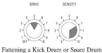
There is no absolute “right” way to set the DENSITY control. However, in general, slower settings are useful for gating out noise present behind vocals and acoustic instruments, while faster settings are useful for tightening up the sound of percussion instruments (e.g., a kick or snare drum).
GAIN REDUCTION (dB) Meter: This meter shows the true peak gain reduction in dB. If the red LED at the far left of the meter lights, no further gain reduction is available.
FREQUENCY Control: Use the control to set the HIGHPASS frequency of the variable filter used in the De-Esser circuitry. Settings between 4-8kHz will yield the best results for vocal processing, while more extreme settings allow the 286A to be used in other non-vocal applications.
THRESHOLD Control: Use this control to set the sensitivity of the De-Esser as a percentage of the average program level at the 286A's input. This means that the De-Esser tracks the input level so the amount of de-essing remains constant with changes in input level.
The De-Esser 1dB and 6dB THRESHOLD LEDs light when the De-Esser is active. These indicate (in dB) how much sibilance reduction is occurring due to the De-Esser.
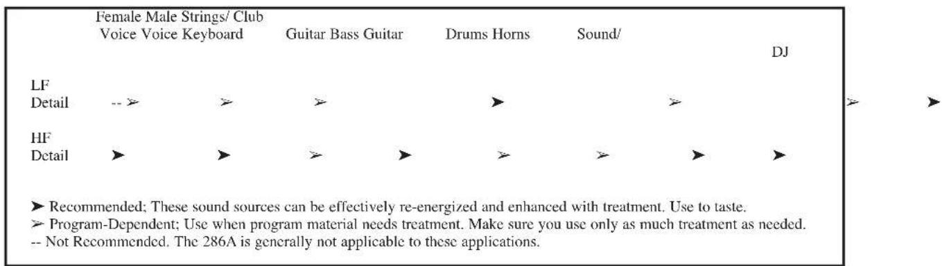
Note: The low and high frequency enhancers are off when their respective DETAIL controls are set to OFF.
LF DETAIL Control: The 286A's Low Frequency enhancement simultaneously applies an 80Hz boost and 250Hz cut to the program. This lets you apply substantial bass boost without making the program sound muddy or boomy due to excessive mid-bass boost.
HF DETAIL Control: This control determines the amount of High Frequency spectral-enhanced signal added to the input signal. Spectral Enhancement is a form of dynamic phase and amplitude equalization. Continuous analysis of the input signal intelligently and automatically determines the amount of equalization necessary at each moment to achieve detailed, defined audio that is never shrill or over-sibilant.
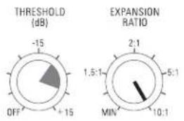
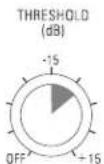
Note: The Expander/Gate is off when the Expander/Gate THRESHOLD is set to OFF.
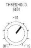
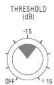
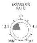
THRESHOLD (dB) Control and LEDs: Adjusting this control sets the level at which the expander/gate will fully open and allow the signal at the input to pass through to the output. Turing the knob fully counterclockwise (to OFF) allows the gate to pass all signals unattenuated, effectively bypassing the gate. Turning the knob fully clockwise causes the gate to attenuate input signals below approximately +15dBu. The amount of attenuation depends on the setting of the Expander/Gate's EXPANSION RATIO.
The THRESHOLD (-) LED (located to the right of the EXPANSION RATIO control) lights when the signal is below the set THRESHOLD. The THRESHOLD (+) LED lights when the signal is above the set THRESHOLD. The combination of these two LEDs also serves as the “POWER ON” function, as one or the other is always on.
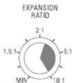
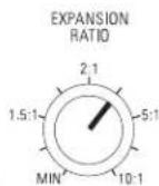
EXPANSION RATIO Control: This control sets the amount of attenuation applied to the input signal once it is below the threshold, from gentle downward expansion (appropriate for mixed program, vocals, etc.), to a hard gating effect (effective for
De-Esser
Enhancer
Expander/Gate
percussion). Fairly low EXPANSION RATIO settings (and higher Expander/Gate THRESHOLDs) work best for downward expansion, whereas higher EXPANSION RATIO settings (clockwise towards 10:1) work best for gating. If a setting produces undesirable "pumping" readjust the Expander/Gate EXPANSION RATIO and THRESHOLD settings.
Note: The attack and release rate of the Expander/Gate are program-dependent -- very fast for transient material (e.g., percussion) and slower for material with slow attack (e.g., vocals).
Readjust as needed to gate out noise -- external, as well as hiss from the unit. The 286A's other processing can add substantial gain to a signal, especially at higher settings, thereby increasing the noise floor.
Output
GAIN (dB) Control and CLIP LED: The OUTPUT GAIN control sets the level at the line output. The OUTPUT GAIN control is especially useful to compensate for the RMS level changes which result from the 286A's processing effects. For example, to decrease the overall gain (e.g., when the 286A's processing has added too much gain), simply turn the OUTPUT GAIN control counterclockwise. The OUTPUT GAIN can also be used to counter any gain reduction after you have adjusted the 286A's controls for the desired amount of processing; adjust the OUTPUT GAIN control clockwise, to add gain as needed.
The red OUTPUT GAIN LED (located to the right of the OUTPUT GAIN control) lights when the 286A Processing Section is clipping; reduce gain via the OUTPUT GAIN control. Set this control so that the OUTPUT CLIP LED never lights. If the OUTPUT CLIP LED is still lit, reduce the gain caused by the 286A's processors (e.g., high Compressor DRIVE settings) or the gain provided by an external processor connected to the INSERT (if any).
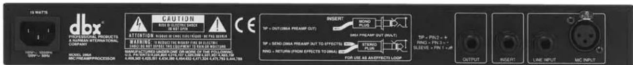
Rear Panel
If the meters on your load device (e.g., tape recorder, mixer, etc.) are in the red and your OUTPUT CLIP LED is not lit, simply reduce the 286A's OUTPUT GAIN until the desired levels are obtained. If your load device is still in the red, reduce its input attenuators (if available).
MIC INPUT Jack: The 286A's MIC INPUT jack supports professional and home studio microphones by accepting either balanced or unbalanced signal through an XLR connector. Pins 2 and 3 are symmetrically balanced and floating; thus, either can be used as "HOT" without difficulty. Pin 2 is in phase with the TIP of all 1/4" connectors. Pin 1 is connected to the 286A's chassis ground.
Note: Use a low impedance mic or a high-to-low impedance matching transformer with a high impedance mic.
LINE INPUT Jack: Use a 1/4" TRS phone plug to connect line level sources to the 286A (e.g., mixer outputs, effects loops, electronic keyboards, etc.). The 286A's LINE INPUT jack accepts either balanced or unbalanced signals. Input impedance is 30kΩ unbalanced, 60kΩ balanced.
Note: In general, this jack does not support microphones with 1/4" plugs. Use an appropriate 1/4"-to-XLR adapter and plug the microphone into the MIC INPUT jack.
LINE OUTPUT Jack: The 286A's LINE OUTPUT jack accepts either balanced or unbalanced 1/4" phone plugs. Nominal output signal levels is 0dBu into 600Ω, and maximum output signal level is >+21dBu into 600Ω. Output impedance is 100Ω unbalanced, 200Ω balanced. The output is tip HOT.
INSERT Jack: The 286A INSERT jack allows you to either add an effects loop directly into the 286A circuitry chain or take a separate mic preamp signal out.
To connect one or more external processors or effects devices (e.g., an equalizer, delay unit, etc.) between the Mic Preamp Section and the Processing Section, insert a 1/4" TRS plug carrying the external device's output signal fully into the 286A's INSERT jack; the TIP acts as a Send, carrying the signal from the Mic Preamp Section at an impedance of 100Ω, while the RING acts as a Return for external devices to feed the 286A's processing circuitry (i.e., 286A's compressor, de-esser, etc.). This operation requires a Y-cable. When using INSERT as a direct in to the Processing Section, MIC GAIN control, HIGHPASS button and PHANTOM POWER will not be active.
To use the INSERT jack to MULT the preamp out (i.e., to provide an output with a buffered version of the signal after the Mic Preamp circuitry, but before the Processing Section), insert a Mono 1/4" plug fully into the INSERT jack, then pull the plug out one click. Plug the other end of the cable to the appropriate load. This will still allow the original signal path to continue to the Processing Section without interruption.
Note: If the plug is accidentally pushed fully into the INSERT jack, it will break off the connection between the Mic Preamp and Processing Sections; in this case, there would be no signal at the 286A's LINE OUTPUT jack.
AC Power: Connect the AC power cord to the AC receptacle on the back of the unit. Route the AC power cord to a convenient power outlet away from audio lines. The unit may be turned on and off from a master equipment power switch.
CONNECTING THE 286A TO YOUR SYSTEM
Basic Connection
The 286A can be used with any low-level microphone signal (via the MIC INPUT) or any line-level device (via the LINE INPUT). Some common line-level devices include: mixing consoles, electronic musical instruments, patch bays, and signal processors. For all connections, refer to the following steps:
- Turn Off all equipment before making any connections.
- Mount the 286A in a rack. (Optional)
Caution: Never remove the cover. There are no user-serviceable parts inside.
The 286A requires one rack space (height) and one rack space (width). It can be mounted above or below anything that doesn't generate excessive heat, since it requires no special ventilation. Ambient temperature should not exceed 113°F (45°C) when equipment is powered.
- Make connections via rear panel jacks and connectors according to your requirements.
A. Connect a microphone to the MIC INPUT XLR connector or a line level source to the 1/4" LINE INPUT jack.
Important: DO NOT connect anything other than a microphone to the MIC INPUT.
B. Connect the load (e.g., mixer, tape recorder, etc.) to the 286A's LINE


Mic Preamp/
Processor
286A
OUTPUT jack.
C. Connect an external processor or effects device to the 1/4" INSERT jack. (Optional)
- Connect the AC power cord to the AC power receptacle on the back of the unit.
Note: We recommend you always power on the unit with the MIC GAIN control set to its minimum level (fully counterclockwise). This will help in safeguarding your system against sudden spikes and surges, as well as possible acoustical feedback if a microphone is connected and left "open."
Note: Check the line voltage (printed on 286A) and verify that it is correct.
BASIC OPERATION
Understanding the 286A's Mic Preamp
The 286A's Mic Preamplification Section includes support for phantom-powered mics, a highpass filter, and an input gain control. Note that these controls are applied to the input signal before the signal is processed by the 286A's Processing Section.
Phantom power is available at the push of a button, providing +48VDC to phantom-powered microphones. The 286A's phantom power is sufficient for most microphones. However, some vintage condenser mics may require a separate power source.
Press the HIGHPASS button In to cut signals below 80Hz by 18dB/octave, effectively filtering out mic proximity effects, hum, rumble, wind and other low frequency “undesirables.”
Use the MIC GAIN control to achieve the best definition and character possible from your microphone. The 286A's Mic Preamp delivers up to 60dB of sonically transparent gain to reveal the detail and audio signature of even the most esoteric mics. It transforms their low level output signal to a high level, high current signal that is internally fed to the 286A's main processing chain (i.e., compressor, de-esser, etc.)
Using the Mic Preamp Alone (i.e., Using the 286A as a Dedicated Mic Preamp)
Processing Section
To use the 286A as a dedicated mic preamp, simply press the BYPASS button to defeat the Processing Section circuitry. This allows you to use the Mic preamp's PHANTOM POWER switch, HIGHPASS button and MIC GAIN control without routing the signal through any of the processing circuitry.
The 286A's Processing Section consists of four specific processors: Compressor, Deesser, Enhancer, Expander/Gate. These four processors can be used in any combination or the 286A can be set as a dedicated single-function processor (refer to the following pages).
Compressor
A compressor is a device that changes its gain in response to the signal at its input. Many compressors have a user-selectable level, called THRESHOLD, to help determine when compression occurs. If the input signal is low in level (below the threshold of compression) the compressor gain remains fixed. If the input increases above the threshold of compression, the gain begins to decrease (i.e., the amount of gain reduction increases). For very large input signals, the gain can decrease considerably. On the 286A, compression occurs as an input level is “driven” into gain reduction by the DRIVE control; as the DRIVE setting (adjusted clockwise from OFF) increases input gain, the amount of gain reduction also increases. The 286A does not have a Threshold control; the threshold is established by the setting of the DRIVE control.
Use the Drive control to set the amount of gain reduction (i.e., how much the input signal is being compressed). Use the DENSITY control to set the compressor's
release time (i.e., how fast the compression circuit returns the input to its original level).
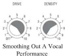
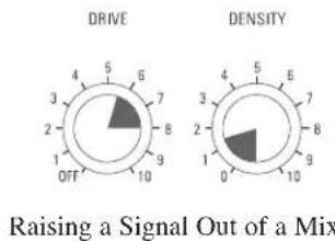
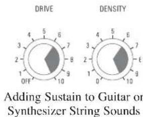
The 286A's patented and versatile Compressor can smoothly and unobtrusively ride gain, and assertively increase punch and density. The 286A achieves its outstandingly transparent audio performance by finely-tuned control circuitry that eliminates the dynamic distortions present in most conventional compressors and limiters. The use of a quiet, low-distortion dbx VCA ensures negligible static distortion and noise. Compression is especially useful for smoothing out a vocal performance, raising a signal out of a mix, fattening kick or snare drums, or adding sustain to instruments (such as an acoustic guitar or bass).
A De-Esser is a device that reduces the high frequency energy present in certain vocalizations, of which the most common is sibilance. Sibilance is the hissing or rushing sound produced by blowing air through a constricted (narrow) mouth opening or across the edge of the teeth, as in the “s” and “sh” in “sash.” Sibilants contain predominantly high frequency components with a sharp rise above 1kHz and most of the energy in the 4kHz to 10kHz band, centered on 6kHz to 8kHz.
Adjust the De-Esser's FREQUENCY control to set the frequency above which the 286A responds to audio containing sibilants. The 286A detects sibilant material by comparing the high-frequency energy of an audio signal to the full bandwidth energy of that signal. When the high-frequency energy is excessive relative to the full bandwidth energy, the 286A quickly reduces the gain, or "de-esses." The frequency control sets the high-pass filter frequency of the high-frequency level detector. For normal vocal de-essing, the frequency should be set between 4 - 8kHz . Further adjustment of the frequency control enables the 286A to be used for processing instrumental material, such as removing "clicks" from a close mic'd piano or acoustic guitar.
Adjust the De-Esser's THRESHOLD control to quickly reduce any sibilance (i.e., excessive vocal sounds like "sss"), high-frequency overload distortion (e.g., a cymbal crash that can overload tape, drive amps into distortion and fatigue listeners), or even guitar string slide noise.
We recommend the 286A's De-Esser for use almost exclusively on single voices or instruments for sibilance. The De-Esser should not be used on mixed program material.
An Enhancer (sometimes called a Spectral Enhancer) adds clarity and detail to vocals or other line level signals by “intelligently” boosting specific frequency ranges.
Use the HF DETAIL control to add high frequency energy to the input signal. Use the LF DETAIL to add punch and definition at the lower end of the spectrum.
The HF Detail circuitry in the 286A uses a dynamic shelving equalizer to provide results superior to even complex equalization. In many situations, the amount of high frequency content in the material you are working with will vary. Typical equalization schemes will produce results which are right some of the time, and completely wrong at other times. But not with the 286A. The equalizer's dynamic operation and sliding corner frequency ensure that high frequency enhancement is applied only when needed and in the specific frequency range necessary to maintain proper spectral balance moment to moment. HF detail is perfect for adding definition to muddy vocals, guitar or horn tracks. It can also add "zing" and crispness to percussion tracks - acoustic or sampled.
De-Esser
Enhancer
Expander/Gate
As you increase the amount of LF Detail, the circuitry boosts lower bass frequencies while simultaneously cutting problem frequencies in the upper bass/low midrange region which often makes program material muddy. Use LF Detail to create a “big,” chesty, male voice or to add fullness and power to lower frequency percussives (e.g., kick, toms, timpani).
A Gate is essentially a device that controls the level of an input signal by “opening” and “closing.” A user-selected level, called THRESHOLD, helps determine when the gate opens and closes. If the input signal is above the threshold, the gate is “open,” allowing the signal to pass. If the input signal is below the threshold, the gate “closes” and the input signal is attenuated. With sufficient attenuation, it effectively cuts that signal off. On the 286A, the amount of attenuation is set with the EXPANSION RATIO control.
The 286A's gate provides more flexibility than traditional switch gates because it actually functions as a combination gate/expander. Where switch gates are generally only suitable for a limited number of uses (e.g., gating percussion), the gate on the 286A acts as a gentle downward expander at low EXPANSION RATIO settings (suitable for vocals, guitar, etc.) and can effectively work as a switch gate when used at high EXPANSION RATIO settings.
When an input signal exceeds the user-selected THRESHOLD, signals pass unaffected. However, when part of a signal is below THRESHOLD, that part is downward expanded. (This differs from gating in that the attenuation effect of downward expansion is gentle.) Downward expansion works well with program material that has a less defined attack and release. Use downward expansion with voice - as opposed to percussive sounds which have a quick, defined attach and release.
Adjust the Expander/Gate THRESHOLD and EXPANSION RATIO controls to prevent headphone leakage or to cut the background noise when gain is added at all the preceding stages of the 286A.
Using the Four Processors in Different Combinations
Note: Too high of a THRESHOLD setting with expansion (i.e., lower EXPANSION RATIOS), may cause the 286A to attenuate the desired portion of the signal, as well as the undesired portion. Too high of an EXPANSION RATIO setting my cause undesirable effects with highly modulated program material like vocals.
Note: The following example is provided as a guide to highlight how the 286A's front panel controls can be used simultaneously for multiple purposes. Suggested settings are specific to this example. Once you have connected the 286A to your system (see page 7), adjust the 286A's controls as required to support your setup and to achieve your desired results (refer to Suggested Settings/Usages, below).
An Example: You are using a condenser microphone to record a vocalist whose “sss” sounds sting while the overall character of the vocal part is rather dull and the vocalist is constantly changing his/her distance from the microphone, and your studio is complete with hum from bad cabling, and noise from heavy construction work nearby. The 286A can be used to rectify each of these problems and also provide additional processing to highlight the best qualities of the vocal performance.
Press the PHANTOM POWER button in to support the phantom power mic (after reducing playback gain).
Press the HIGHPASS button in to reduce the hum.
Adjust the Compressor DRIVE and DENSITY controls to smooth out the vocal performance. To slow the compressor's release time, set the DENSITY control to 0.
Set the De-Esser frequency control to 4kHz (12:00 position).
Adjust the De-Esser THRESHOLD control to reduce the vocalist's sibilance.
Use the HF DETAIL, to taste, to add life to the vocal. Defeat the LF DETAIL by setting it to OFF.
Set the Expander/Gate THRESHOLD and EXPANSION RATIO controls starting with a setting of around 11:00. Adjust these controls so that background noises are gated out when the vocal part is low or not present.
Because minimal processing levels often produce the best results, the 286A's processing should initially be applied conservatively (to taste); avoid overusing an effect, unless it is absolutely necessary. (For example, use De-Essing for sibilance or high frequency distortion only; otherwise, turn the control OFF. Or, for material already rich in high frequencies, set the HF DETAIL to Off, or use it minimally.)
This will ensure that the 286A's circuitry produces superior audio without any artifacts.
Suggested Settings/Usages
- Expander/Gate
Note: The Expander/Gate is OFF when the Expander/Gate THRESHOLD is set to the "off" position.
Suggested Initial Gate settings:
Gating Dry Percussive Sounds (i.e.: Snare Drum, Kick Drum)
Gating Hum or Buzz from Live Instruments or Recorded Tracks
Gating Sounds that have Longer Decay
(i.e.: Cymbal, Piano)
Downward Expansion to Reduce
Noise Under Smooth Sounds
(i.e.: Vocals, Woodwinds)
•Enhancer
Note: The High and Low Frequency Enhancers are OFF when their respective DETAIL controls are set to the "off" position.
Suggested Usage:
Mic Preamp/
Processor
•Compressor
Note: The Compressor is OFF when the Compressor DRIVE is set to the "off" position.
Suggested Initial Compressor settings:
PROBLEMS, POSSIBLE CAUSES, SOLUTIONS
Noise Rushups, Hiss Buildup
Always verify that the problem is not in the source material being fed into the 286A, or in the other parts of the system. If you still have problems when using the 286A, consider the following remedies.
Higher DRIVE settings on the compressor often add gain to the signal. If the signal already has substantial hiss, the compression can actually increase the hiss. As a compressor releases and the gain of the input signal increases, background noise and hiss can increase. This is called noise rushup. Remedy this by using compression conservatively. Also, to reduce noise rushups, especially during pauses, lower the Compressor DENSITY setting. For both cases, set the Expander/Gate to match the compressor's release time, thereby gating out the noise or hiss as much as possible without truncating the signal.
Increased hiss can also result from high frequency “detailing.” The HF DETAIL enhancer estimates how much high frequency boost is appropriate for a given input signal. If the signal is dull but noisy (e.g., vocals recorded to a bad cassette), the HF DETAIL will make it brighter and can pull up hiss to objectionable levels. (The hiss will often be audibly modulated by the material because the HF DETAIL is adaptive to the material.) Reduce the setting of the HF DETAIL control until the effect is no longer objectionable.
dbx Professional Products manufactures several processors that are more suitable for this type of low-quality material because they have built-in dynamic single-ended noise reduction circuits. The dbx Project 1 296 Spectral Enhancer features hiss reduction and Spectral Enhancement all in one unit. The dbx 563X and 929 "Silencers" provide over 30dB of hiss reduction only.
For multitrack studio applications, consider gating out the hiss during the initial recording, then adding HF DETAIL enhancement afterwards, during mixdown.
With certain combinations of controls, especially when they are used at more extreme settings (towards fully clockwise), distortion or artifacts may occur. In this case, lessen one of more of the controls in use. For example, higher DRIVE settings on the compressor often add gain to low-level signal, especially when used in conjunction with other controls. To reduce distortion, simply reduce the compression setting. If you still want more compression, return the compression to its previous setting, and reduce one or more of the other controls which commonly increase gain (e.g., Enhancer DETAIL controls, MIC GAIN, etc.).
Setting the DENSITY control higher than the 12:00 position can sometimes cause audible distortion in the bass because the very fast release time begins to modulate each individual cycle of the bass waveform. If this occurs, turn down the DENSITY control. (Patented circuitry in the 286A greatly reduces this effect when compared to many other compressors operated at equally fast release times).
Higher Expander/Gate settings can cut off sounds prematurely, specifically after a sudden transient or loud note has decayed. This could result in unintelligible vocals, incomplete chords, inferior cymbal splashes, lost reverb tails, etc. To retain the complete input signal, but still maintain required expansion and gating (e.g., to reduce settings until the complete signal is adequately restored. This means that you should set the Expander/Gate controls so that the red (-) THRESHOLD LED (located to the right of the EXPANSION RATIO control) does not light until the required signal is finished.
With higher settings of the De-Esser THRESHOLD or Expander/Gate THRESHOLD controls, a vocal performance can be marred by resultant lisps (i.e., where s and z sounds are heard as th sounds). Lisps can usually be corrected by reducing the De-Esser THRESHOLD, or the Expander/Gate THRESHOLD, or both.
If high frequency energy in the audio is producing shrillness or excessive brightness, try reducing the HF DETAIL or increasing the De-Esser THRESHOLD (if the audio is a single track), as appropriate.
Although the HIGHPASS button works effectively to reduce hum, rumble, wind noise, etc., at the input, LF DETAIL can restore low frequency power to objectionable levels if used too liberally. This is especially true if the rear panel INSERT is used; this places a unit (e.g., an equalizer) directly between the Mic Preamp Section and Processing Section of the 286A - hum or other undesirable low frequencies “inserted” by the device cannot be corrected by the HIGHPASS button. In most cases, make sure the LF DETAIL is used conservatively.
Increase MIC GAIN or Compressor DRIVE.
Audible Distortion, Etc.
Sound Cutting Off
Lispy Vocals
Shrillness or Excessive Brightness
Low Rumble or Excessive Low Frequencies
No Gain Reduction Metering Shown When Compression is In (i.e., Compression DRIVE control is active).
TECHNICAL SUPPORT AND FACTORY SERVICE
The 286A is an all-solid-state product with components chosen for high performance and excellent reliability. Each 286A is tested, burned in and calibrated at the factory and should require no internal adjustment of any type throughout the life of the unit. We recommend that your 286A be returned to the factory only after referring to the manual and consulting with Customer Service.
Our phone number, fax number and address are listed on the back cover of this manual. When you contact dbx Customer Service, be prepared to accurately describe the problem. Know the serial number of your unit -- this is printed on a sticker attached to the rear panel.
Note: Please refer to the terms of your Limited Two-Year Standard Warranty, which extends to the first end-user. After expiration of the warranty, a reasonable charge will be made for parts, labor, and packing if you choose to use the factory service facility. In all cases, you are responsible for transportation charges to the factory. dbx will pay return shipping if the unit still under warranty.
Shipping Instructions: Use the original packing material if it is available. Mark the package with the name of the shipper, and with these words in red: DELICATE INSTRUMENT, FRAGILE! Insure the package properly. Ship prepaid, not collect. Do not ship parcel post.
REGISTRATION CARD AND USER FEEDBACK
We appreciate your feedback. After you have an opportunity to use your new 286A, please complete the Registration Card and return it.
WARRANTY
This warranty is valid only for the original purchaser and only in the United States.
- The warranty registration card that accompanies this product must be mailed within 30 days after purchase date to validate this warranty. Proof-of-purchase is considered to be the burden of the consumer.
- dbx warrants this product, when bought and used solely within the U.S., to be free from defects in materials and workmanship under normal use and service.
- dbx liability under this warranty is limited to repairing or, at our discretion, replacing defective materials that show evidence of defect, provided the product is returned to dbx WITH RETURN AUTHORIZATION from the factory, where all parts and labor will be covered up to a period of two years. A Return Authorization number must be obtained from dbx by telephone. The company shall not be liable for any consequential damage as a result of the product's use in any circuit or assembly.
- dbx reserves the right to make changes in design or make additions to or improvements upon this product without incurring any obligation to install the same additions or improvements on products previously manufactured.
- The foregoing is in lieu of all other warranties, expressed or implied, and dbx neither assumes nor authorizes any person to assume on its behalf any obligation or liability in connection with the sale of this product. In no event shall dbx or its dealers be liable for special or consequential damages or from any delay in the performance of this warranty due to causes beyond their control.
FRANÇAIS

ATTENTION:
CAUTION
RISK OF ELECTRIC SHOCK DO NOT OPEN

RISQUE DE CHOC ELECTRIQUE
NE PAS OUVRIR
WARNING: TO REDUCE THE RISK OF FIRE OR ELECTRIC SHOCK DO NOT EXPOSE THIS EQUIPMENT TO RAIN OR MOISTURE
Adresse fabricant: 8760 S. Sandy Parkway
Sandy, Utah 84070, USA
dbx Professional Products
Vice President of Engineering
8760 S. Sandy Parkway
Sandy, Utah 84070, USA
October 4, 1996
PROBLÈMES, CAUSES, SOLUTIONS 27
BRUIT DE FOND/SIBILANCES 27
DISTORSION, ETC. 27
SONS TRONQUÉS 28
CHUINTEMENTS 28
SON AGRÉSSIF/ BRILLANCE EXCESSIVE 28
RONFLEMENTS/BASSES FRÉQUENCES EXCESSIVES 28
ABSENCE DE RÉACTION DU VUMÈTRE EN MODE COMPRESSION ..... 28
SYNOPTIQUE 63
CARACTÉRISTIQUES TECHNIQUES 64
| Female Male Strings/ Club Voice Voice Keyboard | Guitar Bass Guitar | Drums Horns | Sound/ | DJ | ||
| LF Detail | -- ( | ( | ( | ) | ( | |
| HF Detail | ) | ) | ( ) | ( | ( ) | ) |
PROBLÈMES, CAUSES, SOLUTIONS
WARNING: TO REDUCE THE RISK OF FIRE OR ELECTRIC SHOCK DO NOT EXPOSE THIS EQUIPMENT TO RAIN OR MOISTURE
dbx Professional Products
8760 S. Sandy Parkway
Sandy, Utah 84070, USA
dbx Professional Products
Vice President of Engineering
8760 S. Sandy Parkway
Sandy, Utah 84070, USA
- October, 1997
WARNING: TO REDUCE THE RISK OF FIRE OR ELECTRIC SHOCK DO NOT EXPOSE THIS EQUIPMENT TO RAIN OR MOISTURE
dbx Professional Products
8760 S. Sandy Parkway
Sandy, Utah 84070, USA
dbx Professional Products
Vice President of Engineering
8760 S. Sandy Parkway
Sandy, Utah 84070, USA
4 de octubre, 1996
DISTORSION AUDIBLE, ETC 60
CORTE DEL SONIDO 61
VOCALIZACIONES CECEANTES ....61
PROBLEMAS, CAUSAS POSIBLES, SOLUCIONES
Gain Adjustment Range
Phantom Power
CMRR
LINE INPUT
Entrée LINE
LINE-Eingang
Entrada LINE
Impedance
Maximum Level
Gain Adjustment Range
CMRR
INSERT (1/4"TRS phone)
LINE OUTPUT (4"TRS phone)
Gain Adjustment Range
Noise
Frequency Response
Distortion
COMPRESSOR
Circuit de compression
Kompressor
Compresor
Threshold Range
Threshold Characteristics
Compression Ratio
Maximum Compression
Attack Time
Release Time
Distortion
SMPTE Intermodulation Distortion
DE-ESSER
Characteristic
Frequency Range
Release Time
ENHANCER
HF Detail Characteristic
LF detail Characteristic
Floating balanced, Pin 2 Hot
+48VDC, applied to XLR pins 2 and 3 through 6.81kΩ resistors
40dB, typically 55dB
Floating balanced, TIP Hot
30kΩ unbalanced, 60kΩ balanced
+21dBu, balanced or unbalanced
-20dB ... +30 dB
40dB, typically 55dB
Normalled; tip is Send, ring is Return
+21dBu,>+20dBm (600Ω load)
<-84dBu, unweighted (20Hz-20kHz); MIC GAIN Control set to 12:00
<0.01% THD, 20Hz-20kHz, +10dBu
Balanced/Unbalanced
Symmetrisch/asymmetrisch
100Ω unbalanced, 200Ω balanced
+21dBu,>+20dBm (600Ω load)
-30dB ... +10dB
<-80dBu (typically -85dBu, unweighted (20Hz-20kHz); Both Gain Controls set ... 12:00,
all processing controls OFF
20Hz ... 20kHz, +0.5, -0.5dB
<0.08%THD, 20Hz-20kHz, +10dBu, all Processing Controls OFF
-40dBu to +20dBu
OverEasy®
4:1 For input levels beyond 20dB above threshold
30dB
Program-Dependent; >1s for small level increases, down to 10ms for large increases
Program-Dependent;adjustable between approximately 1dB/Sec and 75dB/Sec
Typically <0.05%THD, 20Hz-20kHz, 15dB G/R, +10dBu Output, DENSITY @ 0
<0.05%; 60Hz/7kHz 4:1, 15dB G/R, +10dBu Output Level, DENSITY @ 0
Wideband Gain Reduction
800Hz to 10kHz High Pass, 12dB/octave
Program-Dependent: approximately 1ms/dB
Program-controlled shelving equalizer, approximately 15dB maximum HF boost
Bell-shaped boost @ 80Hz, bell-shaped cut @250Hz, ratio is approximately 2:1
Mic Preamp/
Processor
EXPANDER/GATE
Threshold Range
Expansion Ratio
Maximum Depth
Attack Time
Release Time
OFF ... +15dBu
Adjustable 1.5:1 ... 10:1
50dB
Program-Dependent, approximately 2ms (at maximum attenuation)
Program-Dependent, approxiamtely 10ms/dB
DYNAMIC RANGE
Gamme dynamique
Dynamikumfang
Margen dinámico
Typically 105dB
Power Requirements
Operating Temperature
Net Weight: 4.68 lbs; Shipping Weight: 6.54 lbs
Weight
Poids net/brut
PROFESSIONAL PRODUCTS
H A Harman International Company
8760 South Sandy Pkwy.
Sandy, Utah 84070
Phone: (801) 568-7660
Fax: (801) 568-7662
Questions or comments?
E-mail us at: customer@dbxpro.com
or visit our World Wide Web home page at:
www.dbxpro.com

- OWNER/OPERATOR MANUAL
- WARNING: TO REDUCE THE RISK OF FIRE OR ELECTRIC SHOCK DO NOT EXPOSE THIS EQUIPMENT TO RAIN OR MOISTURE
- U.K. MAINS PLUG WARNING
- WARNING
- FOR YOUR PROTECTION, READ THESE INSTRUCTIONS
- ELECTROMAGNETIC COMPATIBILITY
- SAFETY INSTRUCTIONS
- DECLARATION OF CONFORMITY
- MANUAL CONTENTS
- ENGLISH CONTENTS
- OPERATING CONTROLS
- FRONT PANEL
- INPUT
- BYPASS
- COMPRESSOR
- DE-ESSER
- ENHANCER
- EXPANDER/GATE
- OUTPUT
- REAR PANEL
- CONNECTING THE 286A TO YOUR SYSTEM
- BASIC CONNECTION
- OUTPUT JACK
- BASIC OPERATION
- UNDERSTANDING THE 286A'S MIC PREAMP
- USING THE MIC PREAMP ALONE (I.E., USING THE 286A AS A DEDICATED MIC PREAMP)
- PROCESSING SECTION
- USING THE FOUR PROCESSORS IN DIFFERENT COMBINATIONS
- SUGGESTED SETTINGS/USAGES
- PROBLEMS, POSSIBLE CAUSES, SOLUTIONS
- NOISE RUSHUPS, HISS BUILDUP
- TECHNICAL SUPPORT AND FACTORY SERVICE
- REGISTRATION CARD AND USER FEEDBACK
- WARRANTY
- FRANÇAIS
- CAUTION
- PROBLÈMES, CAUSES, SOLUTIONS
- PROBLEMAS, CAUSAS POSIBLES, SOLUCIONES
- LINE INPUT
- INSERT (1/4"TRS PHONE)
- LINE OUTPUT (4"TRS PHONE)
- DYNAMIC RANGE
- POWER REQUIREMENTS
- OPERATING TEMPERATURE
- PROFESSIONAL PRODUCTS
- H A HARMAN INTERNATIONAL COMPANY
Brand : DBX
Model : 286A
Category : Receiver