580 - Receiver DBX - Free user manual and instructions
Find the device manual for free 580 DBX in PDF.


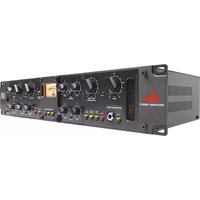
| Product Type | Signal Processor / Receiver |
| Brand | DBX |
| Model | 580 |
| Dimensions | 19" rackmount, 1U (44.5 x 483 x 44 mm) |
| Weight | Approximately 2.5 kg (5.5 lbs) |
| Power Supply | 100-240V AC, 50/60 Hz, 15W |
| Audio Inputs | Balanced XLR, unbalanced 1/4" TRS |
| Audio Outputs | Balanced XLR, unbalanced 1/4" TRS |
| Frequency Response | 20 Hz - 20 kHz (±0.5 dB) |
| Dynamic Range | > 110 dB |
| THD+N | < 0.01% |
| Key Functions | Compression, limiting, de-essing, noise gating, parametric EQ |
| Controls | Front panel knobs and switches, back panel DIP switches |
| Indicators | LED level meters, power and status LEDs |
| Housing Material | Steel chassis, aluminum front panel |
| Operating Temperature | 0°C to 40°C (32°F to 104°F) |
| Maintenance | Wipe with dry, lint-free cloth; avoid solvents |
| Safety | Use only with grounded AC outlets; do not expose to moisture |
| Spare Parts | Available through authorized DBX service centers |
| Repairability | Modular design; service manual available on request |
| Compliance | CE, FCC Class B |
Frequently Asked Questions - 580 DBX
User questions about 580 DBX
0 question about this device. Answer the ones you know or ask your own.
Ask a new question about this device
Download the instructions for your Receiver in PDF format for free! Find your manual 580 - DBX and take your electronic device back in hand. On this page are published all the documents necessary for the use of your device. 580 by DBX.
USER MANUAL 580 DBX
- Please register your product online at www.dbxpro.com. Proof-of-purchase is considered to be the responsibility of the consumer. A copy of the original purchase receipt must be provided for any warranty service.
- dbx warrants this product, when purchased new from an authorized U.S. dbx dealer and used solely within the U.S., to be free from defects in materials and workmanship under normal use and service. This warranty is valid to the original purchaser only and is non-transferable.
- dbx liability under this warranty is limited to repairing or, at our discretion, replacing defective materials that show evidence of defect, provided the product is returned to dbx WITH RETURN AUTHORIZATION from the factory, where all parts and labor will be covered up to a period of two years. A Return Authorization Number must first be obtained from dbx. The company shall not be liable for any consequential damage as a result of the product's use in any circuit or assembly.
- dbx reserves the right to make changes in design or make additions to or improvements upon this product without incurring any obligation to install the same additions or improvements on products previously manufactured.
- The foregoing is in lieu of all other warranties, expressed or implied, and dbx neither assumes nor authorizes any person to assume on its behalf any obligation or liability in connection with the sale of this product. In no event shall dbx or its dealers be liable for special or consequential damages or from any delay in the performance of this warranty due to causes beyond their control.
Technical Support & Service
If you require technical support, contact dbx Technical Support. Be prepared to accurately describe the problem. Know the serial number of your device – this is printed on a sticker attached to the chassis.
Before you return a product to the factory for service, we recommend you refer to this manual. Make sure you have correctly followed installation steps and operating procedures. For further technical assistance or service, please contact our Technical Support Department at (801) 566-8800 or visit www.dbxpro.com. If you need to return a product to the factory for service, you MUST first contact our Technical Support Department to obtain a Return Authorization Number.
NO RETURNED PRODUCTS WILL BE ACCEPTED AT THE FACTORY WITHOUT A RETURN AUTHORIZATION NUMBER.
Please refer to the Warranty information, which extends to the first end-user. After expiration of the warranty, a reasonable charge will be made for parts, labor, and packing if you choose to use the factory service facility. In all cases, you are responsible for transportation charges to the factory. If the product is still under warranty, dbx will pay the return shipping.
Use the original packing material if it is available. Mark the package with the name of the shipper and with these words in red: DELICATE INSTRUMENT, FRAGILE! Insure the package properly. Ship prepaid, not collect. Do not ship parcel post.
580
Table of Contents
Overview 2
Introduction 2
Features 2
Installation ....3
The User Interface ....4
Technical Information ....6
Detail Filters – Frequency Response Plots....6
Block Diagram....7
Specifications....8
Recall Sheet....10
Overview
Introduction
The 580 is a 500 series compliant microphone preamplifier with dedicated front-panel instrument input, making it well suited for microphone or direct instrument recording applications.
A MIC/INSTR switch allows for switching between the microphone or front-panel instrument input jack. A 20dB pad switch can be engaged to attenuate the 580's input for accepting high-output signal levels from "hot" microphones or sources with high sound pressure levels (SPLs), such as kick drums and miked electric guitar cabinets.
+48 Volt phantom power allows the 580 to be used with condenser microphones. The GAIN control provides up to 60 dB of gain. The POLARITY INVERT switch provides additional functionality for multi-miked applications, such as when multi-miking a snare drum from the top and bottom.
The DETAIL circuit can be used to "sweeten" the tone of the source, making dull sources sound more lively and thin sources sound more full. The LOW DETAIL control provides low-frequency boost in conjunction with low-mid cut for enhanced low end without sounding "muddy" or "boxy". The HIGH DETAIL control can be used for adding "clarity" to instruments and "air" to vocals.
The variable LOW CUT control can be used to precisely sculpt the low frequencies of instruments and vocals which don't inherently contain much signal information in the low-frequency region. This can help clean up mixes by preventing the accumulation of low-frequency noise across tracks.
The backlit, vintage-style VU meter makes it easy to see signal levels. Use it in combination with the PEAK LED to optimize the gain for the best signal-to-noise performance without added distortion.
We hope the 580 serves as an indispensable creative tool for your sound processing and music production needs. Thank you for choosing dbx.
Features
- Microphone Preamp With Up To 60 dB Gain
• +48 Volt Phantom Power For Condenser Microphones
• Dedicated Front-Panel Instrument Input
• Detail Circuit For Low / High Tone Sweetening
• Variable Low Cut Control - 20dB Pad
- Polarity Invert Button
• Vintage-Style VU Meter - Signal Peak LED
Installation
FOR 500 SERIES CHASSIS MOUNT USE ONLY!
IMPORTANT NOTE: Many 500 series chassis have the potential to cause noise when preamplifiers are mounted in the slot closest to the power supply. This noise is exacerbated with preamplifiers due to the large amount of gain which they apply (typically 48 dB or more). Therefore, it is recommended that you do not install the 580 into this slot and reserve it for line-level module use only.
To install the 580 into a 500 series chassis:
- Turn off the power to the 500 series chassis.
- Unpack the module and ensure the rear connector is free of debris.
- Align and slide the module into the 500 series chassis, ensuring the connectors on the back properly seat with the connectors in the chassis.
- Install the included screws to secure the 580 to the chassis. Both metric and standard screws are included. Use the correct screw type for your chassis.
- Power on the chassis.
- Enjoy!
WARNING! Do not hot swap 500 series modules! Doing so can potentially cause damage to the 500 series module or chassis. Always power down the chassis when installing or removing 500 series modules.
The User Interface

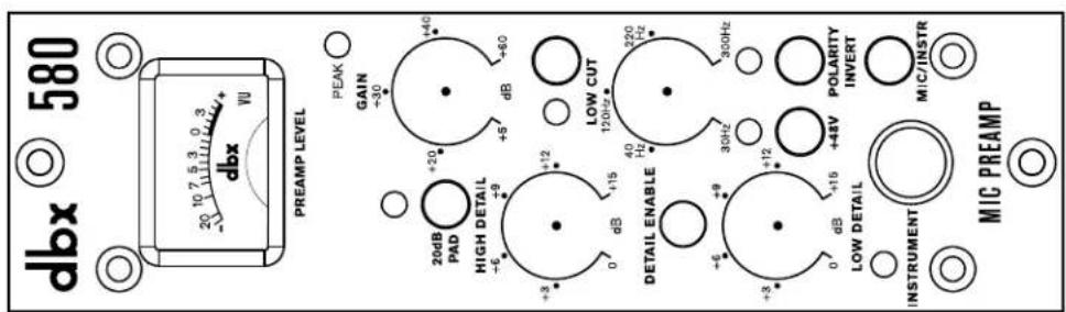
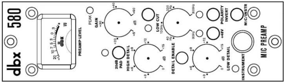
1. VU Meter
This VU meter shows output signal level, with 0 indicating the optimal level (0 VU = +4 dBu).
2. 20dB Pad Button & LED
When this button is engaged, the LED will light and a 20 dB attenuation circuit will be inserted into the signal path post the microphone input. The pad is inserted before the signal is routed through the gain stage. Use the pad to attenuate signals from high-output microphones or sources with high sound pressure levels, such as kick drums and miked electric guitar cabinets. Note that the 20dB Pad does not affect the front-panel INSTRUMENT input.
3. HIGH DETAIL Control
Varies the amount of high-frequency detail applied to the signal when the detail ENABLE button is engaged. This is a high-frequency shelving filter with a corner frequency of 10 kHz and can be used for adding "air" to vocals or "clarity" to solo instruments. See 'Detail Filters - Frequency Response Plots' on page 6 to see a frequency response plot of this control.
4. DETAIL ENABLE Button & LED
Enables the detail circuit which includes the LOW DETAIL and HIGH DETAIL controls. The detail circuit can be used for "sweetening" the tone of the source signal.
5. LOW DETAIL Control
Varies the amount of low-frequency detail applied to the signal when the detail ENABLE button is engaged. This is a two-stage circuit which simultaneously boosts a low-frequency bell filter with a center frequency of 125 Hz and attenuates a bell filter with a center frequency of 400 Hz. Use it to add "weight" to instruments, such as when recording a kick drum or bass guitar direct. See 'Detail Filters – Frequency Response Plots' on page 6 to see a frequency response plot of this control.
6. INSTRUMENT Input Jack
This unbalanced high-impedance jack accepts instrument-level sources, such as electric bass and guitar.
7. PEAK LED
This LED illuminates when the signal level is within 3 dB of clipping. Adjust the GAIN control so that the signal's loudest peaks do not cause this LED to light.
8. GAIN Control
Determines the amount of gain applied to the input signal with up to 60 dB of gain available.
580
9. LOW CUT Button
Engages the low cut circuit and enables the variable LOW CUT control.
10. LOW CUT Control
When the LOW CUT button is engaged, this control sets the frequency below which frequencies will be attenuated using a 12 dB/octave Bessel filter.
11. POLARITY INVERT Button & LED
Engaging this button will invert the polarity of the microphone input signal. This button does not affect the INSTRUMENT input. Engage this button to match polarity when multi-miking an instrument, such as drums, or when using a top/bottom mic pair on a snare drum or front/back mic configuration on a guitar cabinet. The polarity is inverted when the LED is lit.
12. +48V Button
Enables phantom power for use with condenser microphones. It's recommended that the condenser microphone be connected before engaging the +48V button. If connecting a ribbon or dynamic microphone to the 580, make sure the +48V button is disengaged and wait about 15 seconds for the capacitor to discharge before making the connection.
13. MIC/INSTR Button
When this button is in the out position, the chassis' rear-panel MIC input is enabled. When this button is in the in position, the front-panel INSTRUMENT input is enabled.
Technical Information
Detail Filters – Frequency Response Plots
High Detail +15 dB
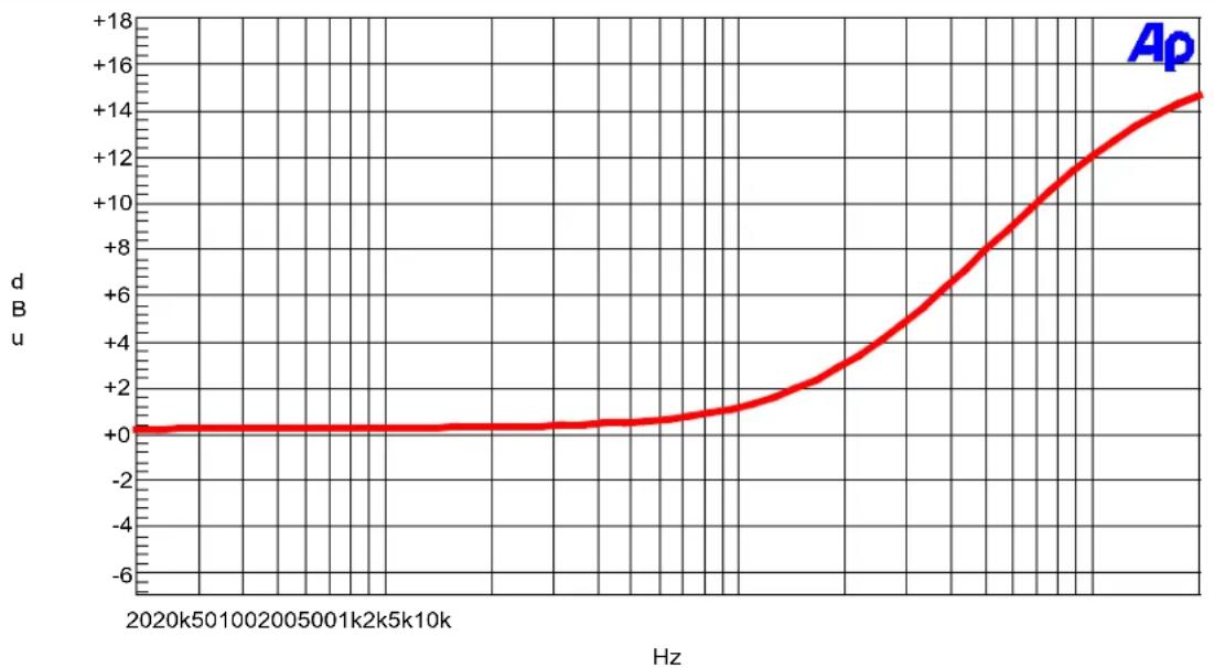
line
| Hz | d u | | -------- | ---- | | 2020k50 | 0 | | 2002005 | 0 | | 5001k2 | 0 | | 5k10k | 0 | | ... | ... | | ... | +18 |Low Detail +15 dB

line
| Hz | d B u | | -------- | ----- | | 2020k50 | +3 | | 2005k00 | +8 | | 2k2k5k10k| +16 | | 1.5k | -6 | | 1.0k | +2 | | 0.5k | +1 | | 0 | 0 |Block Diagram

flowchart
graph LR
    A["Input Microcontroller"] --> B["+48V 20dB Pad"]
    B --> C["Polarity Invert"]
    C --> D["Mic/Inster Switch"]
    D --> E["Amplifier Peak LED"]
    E --> F["Instrument Input"]
    G["Gain Control"] --> H["Low Cut"]
    H --> I["Detail Circuit"]
    I --> J["Output"]
    K["VU Meter"] --> L["Analog meter"]
    L --> M["Amplifier"]
    M --> N["Amplifier"]
    N --> O["Amplifier Peak LED"]
Specifications
MIC PRE INPUT
Type: Electronically balanced/unbalanced, RF filtered
Impedance: 1.7 kΩ
Maximum Input Level: +15 dBu balanced or unbalanced (20dB PAD disabled)
+35 dBu balanced or unbalanced (20dB PAD enabled)
Maximum Gain: 60 dB
CMRR: >60 dB; typically >70 dB from 20 Hz - 20 kHz
INSTRUMENT INPUT (FRONT PANEL)
Connector: Tip-Sleeve 1/4" Jack
Type: Unbalanced
Impedance: 500 kΩ
Maximum Input Level: +21 dBu unbalanced
FUNCTIONS / INDICATORS
Mic/Instrument: Switches between mic input or front-panel instrument input
Gain Control: +5 to +60 dB gain
Phantom Power: +48V DC, front-panel switch, on LED indicator
Pad: 20 dB, front-panel switch, on LED indicator
Polarity Invert: Front-panel switch, on LED indicator
Low Cut: Variable from 30 Hz to 300 Hz, front-panel switch, on LED indicator
Detail: Front-panel switch, on LED indicator
Low Detail: 0 to +15 dB boost, simultaneous bell filter boost (125 Hz center frequency) and bell filter cut (400 Hz center frequency)
High Detail: 0 to +15 dB boost, high-shelving filter (10 kHz corner frequency)
Level Indicators: Backlit VU meter showing output level, Peak LED lights 3 dB below clipping and monitors all stages
OUTPUT
Type: Electronically balanced/unbalanced, RF filtered
Impedance: Balanced 30 Ω, unbalanced 15 Ω
Maximum Output Level: +22 dBu
PERFORMANCE
Equivalent Input Noise (EIN): Typically > -128.0 dBu, 150 Ω source impedance, 22 kHz bandwidth, unweighted
Frequency Response: 18 Hz - 100 kHz, +0/-3 dB
THD+N: <0.006% typical at 0 dBu out, 1 kHz, 30dB gain
POWER
Requirements: +/- 16V DC
Current Draw: 80 mA per power rail
Power Draw: 2.56 watts
PHYSICAL
Rack System: 500 Series Compatible Power-frame
Rack Space 1 Slot
Dimensions (H x W x D) 5.25" x 1.5" x 6" (13.34 cm x 3.81 cm x 15.24 cm)
Weight: 1.3 lbs (0.59 kg)
Shipping Weight: 1.7 lbs (0.77 kg)
Notes: Noise and frequency response specifications are at unity gain.
0 dBu=0.775V rms
Specifications are subject to change without notice.
SOURCE:
SOURCE:
SOURCE:
SOURCE:
SOURCE:
SOURCE:
SOURCE:
The Ground Truth image displays a single, solid horizontal line. According to Rule 2 (UNDERSCORE & LINE RULES), this is a stylistic or background line, not a placeholder underscore. Therefore, the OCR result must ignore it and output nothing or only meaningful text. The provided OCR content is "____", which consists of four underscores. This is an incorrect interpretation of the line as a placeholder, violating the rule that stylistic lines must be ignored. The OCR has hallucinated underscores where none should exist based on the GT's visual context. Hence, the OCR result is inconsistent with the Ground Truth.
SOURCE:

SOURCE:
The Ground Truth image displays a single, solid horizontal line. According to Rule 2 (UNDERSCORE & LINE RULES), this is a stylistic or background line, not a placeholder underscore. Therefore, the OCR result must ignore it and output nothing or only meaningful text. The provided OCR content is "____", which consists of four underscores. This is an incorrect interpretation of the line as a placeholder, violating the rule that stylistic lines must be ignored. The OCR has hallucinated underscores where none should exist based on the GT's visual context. Hence, the OCR result is inconsistent with the Ground Truth.
SOURCE:

The Ground Truth image displays a single, solid horizontal line. According to Rule 2 (UNDERSCORE & LINE RULES), this is a stylistic or background line, not a placeholder underscore. Therefore, the OCR result must ignore it and output nothing or only meaningful text. The provided OCR content is "____", which consists of four underscores. This is an incorrect interpretation of the line as a placeholder, violating the rule that stylistic lines must be ignored. The OCR has hallucinated underscores where none should exist based on the GT's visual context. Hence, the OCR result is inconsistent with the Ground Truth.
CE:
The Ground Truth image displays a single, solid horizontal line. According to Rule 2 (UNDERSCORE & LINE RULES), if the GT contains lines used for stylistic emphasis or as background elements (like ruled paper), the OCR result must ignore them. The OCR content provided is "____", which consists of four underscores. This is incorrect because underscores are not equivalent to a solid line and are not permitted under the “Stylistic/Background Lines (Ignore)” rule. The OCR has hallucinated underscores where none should exist in the GT, violating the rule to ignore stylistic lines. Therefore, the OCR result is inconsistent with the Ground Truth.
The Ground Truth image displays a single, solid horizontal line. According to Rule 2 (UNDERSCORE & LINE RULES), this is a stylistic or background line, not a placeholder underscore. Therefore, the OCR result must ignore it and output nothing or only meaningful text. The provided OCR content is "____", which consists of four underscores. This is an incorrect interpretation of the line as a placeholder, violating the rule that stylistic lines must be ignored. The OCR has hallucinated underscores where none should exist based on the GT's visual context. Hence, the OCR result is inconsistent with the Ground Truth.
SOU

SOURCE:
SOURCE:

SOURCE:
dbx® by HARMAN
Phone: (801) 566-8800
Website: dbxpro.com
Support: dbxpro.com/en-US/support
dbx Professional Products
is a registered trademark of Harman
580 Owner's Manual
Rev A
© 2015 Harman
All rights reserved


- Technical Support & Service
- 580
- Table of Contents
- Overview 2
- Installation ....3
- The User Interface ....4
- Technical Information ....6
- Overview
- Introduction
- Features
- Installation
- To install the 580 into a 500 series chassis:
- The User Interface
- VU Meter
- 20dB Pad Button & LED
- HIGH DETAIL Control
- DETAIL ENABLE Button & LED
- LOW DETAIL Control
- INSTRUMENT Input Jack
- PEAK LED
- GAIN Control
- LOW CUT Button
- LOW CUT Control
- POLARITY INVERT Button & LED
- +48V Button
- MIC/INSTR Button
- Technical Information
- Specifications
- MIC PRE INPUT
- INSTRUMENT INPUT (FRONT PANEL)
- FUNCTIONS / INDICATORS
- OUTPUT
- PERFORMANCE
- POWER
- PHYSICAL
- dbx® by HARMAN
Brand : DBX
Model : 580
Category : Receiver