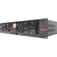
676 - Receiver DBX - Free user manual and instructions
Find the device manual for free 676 DBX in PDF.


| Product Type | Audio/Video Receiver |
| Brand | DBX |
| Model | 676 |
| Dimensions (W x H x D) | 17.1 x 5.9 x 15.4 inches |
| Weight | 24.5 lb |
| Power Supply | 120V AC, 60 Hz |
| Power Consumption | 350 W |
| Number of Channels | 5.1 |
| Amplifier Output | 100 W per channel (8 ohms) |
| Supported Audio Formats | Dolby Digital, DTS, PCM |
| Inputs | 4x HDMI, 3x RCA, 1x Optical, 1x Coaxial |
| Outputs | 1x HDMI (ARC), 1x Subwoofer, Speaker terminals (5 pairs) |
| FM Tuner | Yes, 87.5-108 MHz |
| Remote Control | Included (IR) |
| Energy Efficiency Class | A |
| Standby Power | < 0.5 W |
| Operating Temperature | 32°F to 95°F |
| Spare Parts Availability | Contact DBX support for replacement parts |
| Repairability Index | Score 8/10 (user-replaceable fuses, fan, and input jacks) |
| Maintenance | Wipe with dry cloth; keep vents clear; avoid moisture |
| Safety Certifications | UL, CE, FCC |
Frequently Asked Questions - 676 DBX
User questions about 676 DBX
0 question about this device. Answer the ones you know or ask your own.
Ask a new question about this device
Download the instructions for your Receiver in PDF format for free! Find your manual 676 - DBX and take your electronic device back in hand. On this page are published all the documents necessary for the use of your device. 676 by DBX.
USER MANUAL 676 DBX
- Please register your product online at www.dbxpro.com. Proof-of-purchase is considered to be the responsibility of the consumer. A copy of the original purchase receipt must be provided for any warranty service.
- dbx warrants this product, when purchased new from an authorized U.S. dbx dealer and used solely within the U.S., to be free from defects in materials and workmanship under normal use and service. This warranty is valid to the original purchaser only and is non-transferable.
- dbx liability under this warranty is limited to repairing or, at our discretion, replacing defective materials that show evidence of defect, provided the product is returned to dbx WITH RETURN AUTHORIZATION from the factory, where all parts and labor will be covered up to a period of two years. A Return Authorization Number must first be obtained from dbx. The company shall not be liable for any consequential damage as a result of the product's use in any circuit or assembly.
- dbx reserves the right to make changes in design or make additions to or improvements upon this product without incurring any obligation to install the same additions or improvements on products previously manufactured.
- The foregoing is in lieu of all other warranties, expressed or implied, and dbx neither assumes nor authorizes any person to assume on its behalf any obligation or liability in connection with the sale of this product. In no event shall dbx or its dealers be liable for special or consequential damages or from any delay in the performance of this warranty due to causes beyond their control.
Technical Support & Service
If you require technical support, contact dbx Technical Support. Be prepared to accurately describe the problem. Know the serial number of your device – this is printed on a sticker attached to the chassis.
Before you return a product to the factory for service, we recommend you refer to this manual. Make sure you have correctly followed installation steps and operating procedures. For further technical assistance or service, please contact our Technical Support Department at (801) 566-8800 or visit www.dbxpro.com. If you need to return a product to the factory for service, you MUST first contact our Technical Support Department to obtain a Return Authorization Number.
NO RETURNED PRODUCTS WILL BE ACCEPTED AT THE FACTORY WITHOUT A RETURN AUTHORIZATION NUMBER.
Please refer to the Warranty information, which extends to the first end-user. After expiration of the warranty, a reasonable charge will be made for parts, labor, and packing if you choose to use the factory service facility. In all cases, you are responsible for transportation charges to the factory. If the product is still under warranty, dbx will pay the return shipping.
Use the original packing material if it is available. Mark the package with the name of the shipper and with these words in red: DELICATE INSTRUMENT, FRAGILE! Insure the package properly. Ship prepaid, not collect. Do not ship parcel post.
Table of Contents
Overview 2
Introduction....2
Features....3
Installation 4
Installation Recommendations....4
Making Connections....4
Applying Power 4
Quick Start 5
The User Interface & Connectors 6
Front Panel 6
Rear Panel 7
The Preamp Section 8
Preamp Example Settings 9
Setting The Preamp 9
The EQ Section 10
EQ Example Settings....11
Setting The EQ....11
The Compressor & Limiter Section ......12
Compressor/Limiter Example Settings 16
Setting The Compressor/Limiter....17
Parallel Compression....18
Application Guide 19
Direct Instrument Recording Application....19
Mic Preamp Application....20
Sidechain Application 21
Using The 676 EQ & Compressor At Mixdown....22
Technical Information 23
Block Diagram 23
Compression Graphs 24
EQ Plot....24
Audio Cable Diagrams 25
Replacing The Tube....26
Replacing The Fuse....27
Specifications 28
Recall Sheet 30
Overview
Introduction
The dbx ^® 676 is a single-channel tube microphone preamplifier and channel strip processor with 3-band semi-parametric EQ, compressor, and PeakPlus ^™ limiter. When used at the front of a digital audio workstation, tracks will take on more analog warmth and sheen when compared to preamps built into standard audio recording interfaces.
The 676 preamp is a Class A, high-voltage (250V) vacuum tube design that can accommodate microphones or direct instrument connections thanks to the easily accessible front-panel Hi-Z instrument input. Use the pre-tube GAIN control to dial in just the right amount of tube drive, then adjust the POST TUBE ATTENUATION control to set your gain back to unity. Keep the pre-tube GAIN low and raise the POST TUBE ATTENUATION for an open, clean sound. Or, turn the pre-tube GAIN up and lower the POST TUBE ATTENUATION for a tone that's rich in harmonics and analog warmth. The 676 provides up to 55 dB of gain, a 20 dB pad, +48 volt phantom power, and polarity inversion, making it well suited for a wide variety of recording and live sound applications. Use the insert jack to patch in your favorite outboard compressor, EQ, or any other signal processor post the preamp.
If you can't quite achieve the tone you're after with mic selection and placement alone, use the built-in semi-parametric EQ to fine-tune the tone of the source. Engage the 80 Hz low cut filter to help keep the mix clean and maximize headroom by eliminating subsonic plosives, hum, and microphone vibration noise.
The 676's VCA compressor design was taken from the revered dbx 162SL and delivers smooth, low-distortion compression characteristics, as well as very fast attack/release capabilities for shaping drum transients. Sources can be compressed gently by engaging the OVEREASY switch (soft-knee mode) or aggressively by disengaging the OVEREASY switch (hard-knee mode). Use the compressor to beef up instruments and voices, smooth out level fluctuations, and make your tracks more 'mix-ready'. Compression attack and release times can be set manually or be program-dependent by engaging the AUTO switch. Use the compressor's sidechain jack to insert an outboard EQ for frequency-weighted compression, such as de-essing, or for other creative sidechaining applications. The PeakPlus limiter can be used for level-critical applications, where you want to keep the output level under control no matter how loud the source gets.
PREAMP and COMPRESSOR / LIMITER outputs are provided for parallel compression applications or for recording an uncompressed backup, so there's no need to worry about over-compressing a recorded track.
Whether you're working in the studio or on the stage, the 676 adds harmonically-rich, warm analog tones to your sound sources, at a fraction of the cost of other comparable products in its class.
Thanks for choosing dbx.
676
Features
- Discrete, Class A, High-Voltage Tube Microphone Preamplifier
• 55 dB of Preamplifier Gain
• +48V Phantom Power - 20 dB Pad
- Polarity Invert Switch
• 80 Hz Low Cut Switch - Pre-Tube Gain & Post-Tube Attenuation Controls for Varying the Amount of Tube Drive
• 3-Band Semi-Parametric EQ with Sweepable Mid Frequency
• 162SL-Style Compressor - dbx PeakPlus™ Limiter
• LED Backlit Vintage-Style VU Meter with Selectable Meter Source
• Front-Panel Hi-Z Instrument Input
• 1/4" Preamp Insert Jack
• 1/4" Compressor Sidechain Jack
• Electronically Balanced XLR & TRS Preamp & Compressor / Limiter Outputs
Installation
Installation Recommendations
FOR RACK MOUNT USE ONLY. Install the 676 in a standard 19" rack with the provided rack screws. The 676 should not be mounted above or below anything that generates excessive heat. Ambient temperatures should not exceed 95°F (35°C) when equipment is in use.
Making Connections
WARNING! If connecting a ribbon or dynamic microphone, ensure the +48V button is disengaged before connecting the microphone to the 676.
The 676 has balanced line outputs that can be connected to any balanced or unbalanced line-level device. To connect the 676 to your system:
- Ensure the power is turned off on all interconnecting equipment and the 676 before making audio connections.
- See 'Application Guide' on page 19 for application system diagrams and notes which can be used for reference when connecting the 676 to your system.
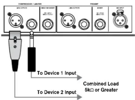
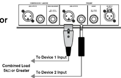
- Make audio connections via the XLR or 1/4" TRS connectors according to application needs (see 'Audio Cable Diagrams' on page 25 for additional information on cable wiring). Either the XLR or 1/4" output connectors for each output (i.e., PREAMP or COMPRESSOR / LIMITER output) can be used for balanced or unbalanced connections. Connecting to both XLR and 1/4" outputs simultaneously (as shown in the below diagram) is perfectly acceptable as long as the combined parallel load is 5kΩ or greater. This is typically not a problem since most modern-day audio devices have been designed with high-impedance line inputs. If desired, parallel resistance calculators can be found online and used to verify if the parallel load meets this criteria. Simply enter the input impedance for the two receiving devices into the calculator to calculate the combined parallel load. Note that connecting both XLR and 1/4" outputs to an unbalanced and balanced input simultaneously will cause the balanced line to become unbalanced.
or
Applying Power
- Ensure your monitoring system is turned down before applying power to the 676.
- Connect the power cord to the AC power inlet on the 676's back panel and route the AC power cord to a convenient power outlet away from audio lines.
- Turn the 676 power switch to the on position.
Quick Start
Follow these steps to get up and running fast:
- Turn the GAIN and POST TUBE ATTENUATION controls all the way down and disable the EQ and Compressor/Limiter by disengaging the EQ ENABLE and COMP/LIM ENABLE buttons.
- If connecting a bass or guitar to the INSTRUMENT INPUT jack on the front panel, engage the INSTRUMENT INPUT ENABLE button. If connecting to the MIC INPUT jack on the rear panel, disengage the INSTRUMENT INPUT ENABLE button.
- Engage the +48V button if a condenser microphone which requires it is connected to the 676, otherwise, disengage the button.
WARNING! If connecting a ribbon or dynamic microphone, ensure the +48V button is disengaged before connecting the microphone to the 676.
-
Engage the INPUT METER SELECTION button to monitor input signal level on the VU meter.
-
With source signal present, raise the GAIN control until the input PEAK LED lights then back it off slightly so the LED goes out. If the PEAK LED lights when the GAIN control is set very low, engage the 20dB PAD button then try again.
-
Raise the POST TUBE ATTENUATION control until the desired amount of output gain is achieved, making sure not to clip the input on the next device. For cleaner tones, lower the GAIN control and raise the POST TUBE ATTENUATION control. For warmer tones, raise the GAIN control and lower the POST TUBE ATTENUATION control.
-
Engage the POLARITY INVERT button if multi-miking a source and polarity inversion is required for matching polarity with the other mic(s). Engage the 80Hz button if the source signal does not contain useful content below 80 Hz. See 'The Preamp Section' on page 8 for additional information on these buttons.
-
Once microphone selection and position have been decided, enable the EQ with the EQ ENABLE button then adjust the EQ settings to taste if any further tone shaping is required. If no EQ is required, leave the EQ ENABLE button disengaged. See 'The EQ Section' on page 10 for further information on using the EQ.
-
Compression and limiting can be used to smooth out overly-dynamic source signals. If you wish to use compression and/or limiting, you must be connected to the COMPRESSOR / LIMITER output. Enable the compressor/limiter with the COMP/LIM ENABLE button and adjust the compressor/limiter settings to taste. For more information on using the compressor/limiter, see 'The Compressor & Limiter Section' on page 12.
The User Interface & Connectors
Front Panel
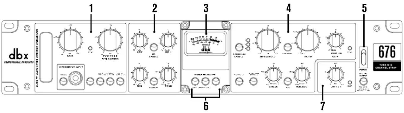
1. Preamp
This is the preamp section, see 'The Preamp Section' on page 8 for further information.
2. EQ
This is the EQ section, see 'The EQ Section' on page 10 for further information.
3. Meter
This LED backlit VU meter displays input signal level, output signal level, or the amount of gain reduction applied by the compressor and/or limiter.
4. Compressor
This is the compressor section, see 'The Compressor & Limiter Section' on page 12 for further information.
5. Power Switch
This switch turns the power to the 676 on and off.
6. Meter Selection Buttons
These buttons select what will be displayed in the VU meter, the selections are: INPUT (input level), OUTPUT (output level), and G.R. (gain reduction applied by compression/limiting).
7. Limiter
This is the limiter section, see 'The Compressor & Limiter Section' on page 12 for further information.
Rear Panel
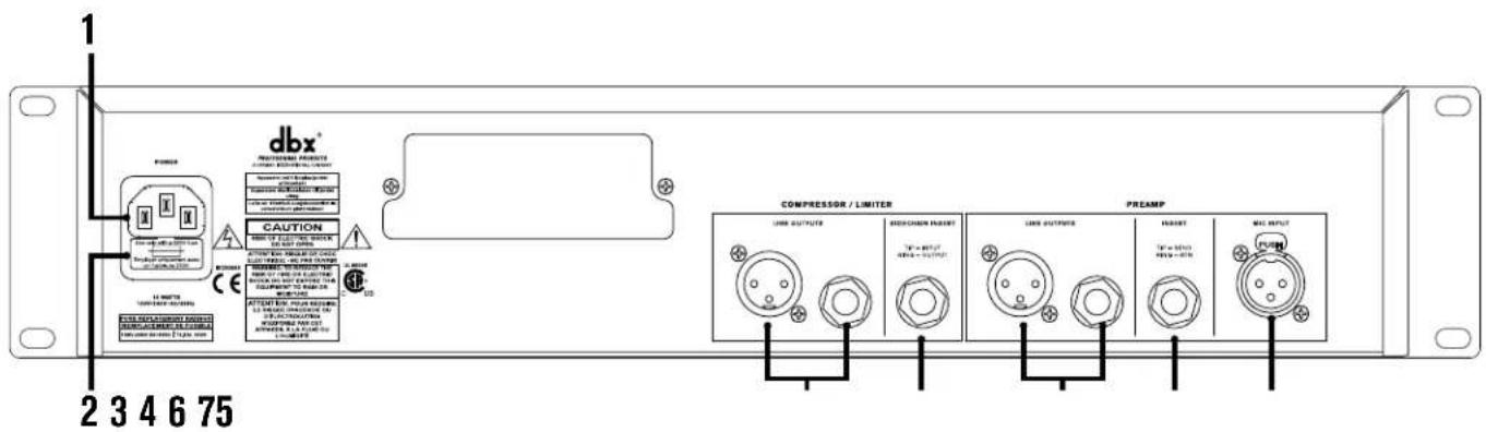
1. Power Connector
Connect the included IEC power cord to this connector and the other end to an available AC outlet.
2. Fuse Drawer
This drawer houses the main power fuse as well as a replacement fuse, see 'Replacing The Fuse' on page 27 for further information.
3. Compressor/Limiter Line Output Connectors
This output carries the signal post-compressor/limiter. Both 1/4" and XLR balanced outputs are provided. The COMPRESSOR / LIMITER output can be used by itself or along with the PREAMP output for parallel compression applications, see 'Parallel Compression' on page 18 for additional information.
4. Compressor Sidechain Insert Connector
Connect an insert cable to this unbalanced connector to patch in another device for processing the signal feeding the compressor's detector circuit. For example, an external EQ could be connected and used for frequency-weighted compression, such as de-essing. See 'Sidechain Application' on page 21 for more information on using this connector.
5. Preamp Line Output Connectors
This output carries the signal post EQ and pre compressor/limiter. It provides a slightly more minimalistic signal path than the COMPRESSOR / LIMITER output. Both 1/4" and XLR balanced outputs are provided. The PREAMP output can be used by itself or along with the COMPRESSOR / LIMITER output for parallel compression applications, see 'Parallel Compression' on page 18 for additional information.
6. Preamp Insert Connector
Connect an external signal processor to this unbalanced connector to process the signal just after the preamp section and before the EQ.
7. Mic Input Connector
Connect a microphone or stage D.I. box to this balanced XLR input connector.
The Preamp Section

1. Gain Control
This control adjusts the amount of input gain applied to the preamp and how hard the tube will be driven. Use lower values to achieve a cleaner, more transparent sound. Use higher values for tones with more analog warmth, harmonics, and sheen.
2. Peak LED
This LED lights when the tube is driven into saturation, or when the circuit post the Preamp/EQ is approaching or has been driven into clipping (the LED will begin to light around 3 dB before the onset of clipping). With the POST TUBE ATTENUATION control fully lowered, this LED can be used to indicate the onset of tube saturation. If this LED only lights when raising the POST TUBE ATTENUATION control or engaging the EQ, the POST TUBE ATTENUATION control should be lowered as clipping the analog circuit post the preamp/EQ will not yield desirable sonic results. See 'Quick Start' on page 5 for more information on referencing this LED when setting up the 676. See 'Block Diagram' on page 23 for a visual representation of the locations in the signal path where this LED references the signal.
3. Post Tube Attenuation Control
This control adjusts the amount of attenuation applied post the tube preamplifier and is meant to be used in conjunction with the GAIN control. For cleaner tones, set this control near the 12 o'clock position and use lower GAIN control settings. For warmer tones, lower this control and raise the GAIN control.
4. Instrument Input Enable Button
This button enables/disables the INSTRUMENT INPUT. When enabled, the signal connected to the INSTRUMENT INPUT will be passed through the 676. When disabled, the 676 will pass the audio from the MIC INPUT connector located on the back panel.
5. Instrument Input Connector
Connect an electric guitar or bass directly to this unbalanced, Hi-Z input.
6. +48V Button
This button enables/disables +48 volt phantom power. Enable it for condenser microphones which require an external power source. Leave this button disabled when connecting a dynamic or ribbon microphone, or a condenser microphone which is powered internally or using its own dedicated power supply.
7. 20dB Pad Button
Engage this button to attenuate the input signal by 20 dB. Use it to prevent the MIC INPUT from being overdriven by loud source signals or high-output microphones.
676
8. Polarity Invert Button
When enabled, this button inverts the polarity of the MIC INPUT signal. Use it with multi-miked applications where polarity inversion is required to match the polarity of the MIC INPUT signal with another miked signal – for example, when using top and bottom mics on a snare drum or miking the front and rear of a guitar cabinet.
9. 80 Hz Low Cut Button
Engage this button to roll-off frequencies below 80 Hz from passing through the 676. This can help reduce low-frequency noise from microphone vibrations, etc.. This low cut filter is a 12 dB/octave Bessel filter.
Preamp Example Settings
The below settings are designed to be used as a starting point. Your results using these settings will vary depending on the variables inherent in your application. For best results, adjust the settings to suit your application as described in the section following the below examples.
VOCALS

ACOUSTIC GUITAR

MIKED ELECTRIC GUITAR

DIRECT BASS GUITAR

Setting The Preamp
- Turn the GAIN and POST ATTENUATION controls all the way down and disable the EQ and Compressor/Limiter by disengaging the EQ ENABLE and COMP/LIM ENABLE buttons.
- If connecting a bass or guitar to the INSTRUMENT INPUT jack on the front panel, engage the INSTRUMENT INPUT ENABLE button. If connecting to the MIC INPUT jack on the rear panel, disengage the INSTRUMENT INPUT ENABLE button.
- Engage the +48V button if using a condenser microphone which requires it, otherwise, disengage the button. If connecting a ribbon or dynamic microphone, ensure the +48 button is disengaged before connecting the microphone to the 676.
- Engage the INPUT METER SELECTION button to monitor input signal level on the VU meter.
- With source signal present, raise the GAIN control until the PEAK LED lights then back it off slightly so the LED just goes out. If the PEAK LED lights when the GAIN control is set very low, engage the 20dB PAD button then try again.
- Raise the POST TUBE ATTENUATION control until the desired amount of output gain is achieved, making sure you don't clip the input on the next device. If the signal is too saturated, lower the GAIN control and raise the POST TUBE ATTENUATION control to clean it up. If you want more saturation, raise the GAIN control and lower the POST TUBE ATTENUATION control.
- Engage the POLARITY INVERT button if multi-miking a source and polarity inversion is required for matching polarity with the other mic(s).
- Engage the 80Hz button if the source signal does not contain useful content below 80 Hz.
The EQ Section
The semi-parametric EQ provides a way to make broad tonal adjustments on the source. Of course it's best to fix a tonal issue at the mic by adjusting the mic placement, trying different mic polar patterns, or swapping the mic for another. However, if you must make a mic work for the occasion and have already done all of these things then reaching for the EQ just may be what's needed. When tracking, it's best used for subtle enhancements, such as adding a tinge of air to an acoustic guitar or vocal, adding a little more definition to a bass, or helping remove some low-mid mud from distorted electric guitars.
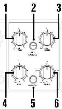
- Low Control [-15 dB to +15 dB]
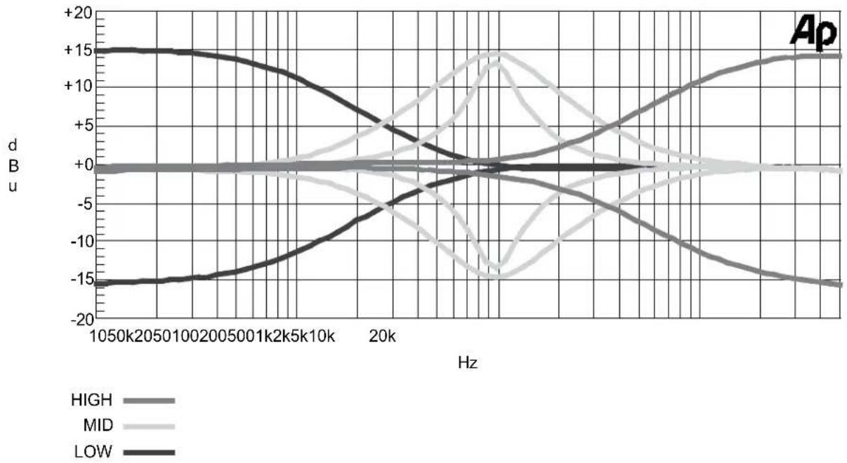
This control adjusts the amount of low-frequency boost or cut. This is a shelving type filter with a fixed frequency of 100 Hz and a slope rate of 12 dB/octave.
- EQ Enable Button
Press this button to enable/disable the EQ – the EQ is enabled when the button's LED is lit.
- High Control [-15 dB to +15 dB)]
This control adjusts the amount of high-frequency boost or cut. This is a shelving type filter with a fixed frequency of 10 kHz and a slope rate of 12 dB/octave.
- Mid Control [-15 dB to +15 dB]
This control adjusts the amount of mid-frequency boost or cut. This is a peaking (bell) type filter.
- Narrow Button
This button changes the 'Q' factor of the mid-frequency peaking filter. When the button is enabled (LED on), the filter becomes more narrow and has a Q of 2.9. When disabled (LED off), the filter is wider and has a Q of 0.9.
- Mid Freq [100 Hz - 8 kHz]
This control adjusts the center frequency of the mid-frequency peaking filter.
EQ Example Settings
The below settings are designed to be used as a starting point. Your results using these settings will vary depending on the variables inherent in your application. For best results, adjust the settings to suit your application as described in the section following the below examples.
VOCALS
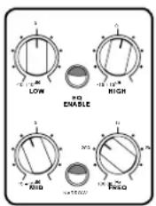
ACOUSTIC GUITAR

MIKED ELECTRIC GUITAR

DIRECT BASS GUITAR

Setting The EQ
- Engage the EQ ENABLE button.
- While monitoring the source signal, adjust the LOW and HIGH knobs to tailor the low and high frequencies to your liking.
- To adjust midrange frequencies, set the MID control to around the 3 o'clock position or until the boost is quite noticeable.
- Sweep the FREQ control until you locate the mid frequencies you wish to alter.
- Set the NARROW button to the desired setting. For example, engage the NARROW button for applications where you want to affect less of the surrounding frequencies (such as when removing the low-mid mud from distorted electric guitars but want to retain the low-end body of the tone). Disengage the NARROW button for a broader, more natural sounding filter – for example, when boosting to add focus to the source.
HINT: In most applications, engaging the NARROW button for cuts and disengaging it for boosts will yield the best results.
- Adjust the MID control for the desired amount of boost or cut.
- Audition the signal and try engaging and disengaging the NARROW button one more time to see which setting gets you closer to the desired sound.
- Re-adjust the POST TUBE ATTENUATION control if necessary. For example, if you have applied ample amounts of EQ boost, the input PEAK LED may light, indicating that you need to lower the POST TUBE ATTENUATION control. Conversely, if you have applied ample amounts of EQ cut, you may want to raise the POST TUBE ATTENUATION control to compensate. In most cases, when applying subtle EQ, no adjustment or very little adjustment may be necessary.
The Compressor & Limiter Section
These days, deciding whether or not to compress a signal while tracking is a matter of personal preference. It was common practice in the days of analog tape to keep the lower-level portions of an audio signal well above the noise floor inherent in magnetic tape. The tape itself could also add a marginal amount of compression. Similarly, in the early days of 16-bit digital audio, many engineers still preferred to use this method to prevent the loss of resolution in the lower bits while also preventing the A/D (analog to digital) converters from clipping (which sounds nothing like driving analog tape!).
With the advent of 24-bit digital audio recording (with a theoretical dynamic range of 144 dB), compressing audio during the tracking stage to fit it on to the recorded medium was no longer necessary. Signals could now be recorded at lower levels without worry of noise, graininess, or clipping the A/D converters. This is true, however, some engineers still prefer to track using light to moderate amounts of compression (particularly on more dynamic sources such as drums, bass, acoustic guitar, clean electric guitar, and vocals) and then apply additional stages of compression during the mixing process. These engineers will argue that spreading the compression task amongst multiple cascaded compressors during the recording/mixing process can sound more natural than applying a large amount of compression using a single compressor. This also allows them to use different 'flavors' of compressors during the process and emulate the same workflow used by engineers for decades for creating the sounds we still love today. Some argue that a high-quality analog compressor simply sounds better than many of the software compressor plug-ins available. Or that it's better to get things 'in-line' up-front in the analog world, before going digital. Of course you wouldn't want to ruin a perfectly good take due to over-compression either. Well, the 676 has a trick up its sleeve for that too! More about that in a moment. What it really comes down to is how you prefer to work and which workflow allows you to best create your artistic vision.
The 676 compressor can be effectively used to apply the first round of transparent dynamic control with around 2-5 dB of compression applied. Recording a signal using the 676 compressor in this way can:
- Provide a more engaging headphone mix for musicians during the recording process, thereby inducing a better musical performance and adding more life to the track.
- Create a more dynamically-consistent and analog-sounding initial mix, making your recorded tracks more 'mix-ready'.
- Tighten-up drum tracks.
- Eliminate one stage of compression in your DAW, saving time later in the process and freeing up computer CPU resources when it comes time to mix.
The 676 compressor is also capable of extremely fast attack and release times, which can be useful for effectively controlling transients of drums and other percussive instruments. However, care should be taking during the tracking stage to ensure you don't over-compress or cause distortion due to overly-fast attack and release times – experience is key here. If you're worried about setting the compressor wrong and ruining an otherwise great take, you can simultaneously record a second track with no compression applied using the PREAMP output. Recording both of these outputs simultaneously can also be used for parallel compression applications, see 'Parallel Compression' on page 18 for more information. A better option may be to bounce through the 676 compressor during the mixing stage if your A/D and D/A converters are of good quality, see 'Using The 676 EQ & Compressor At Mixdown' on page 22 for more information.
When recording extremely dynamic instruments or vocals (for example, a singer who whispers one moment and screams the next), another option is to record the uncompressed signal using the PREAMP output and send the compressed signal from the COMPRESSOR / LIMITER output to the headphone mix. If needed, the limiter can be used in conjunction with the compressor if the level fluctuations are extreme. This can provide the artist with a more dynamically-consistent headphone mix where their instrument or voice sits better, allowing them to focus on their performance.
676
The PeakPlus limiter uses Intelligent Predictive Limiting to determine how much gain reduction to apply and can be used for either subtle transient events or level-critical applications, where you want to keep dynamics under control no matter how loud the source becomes.
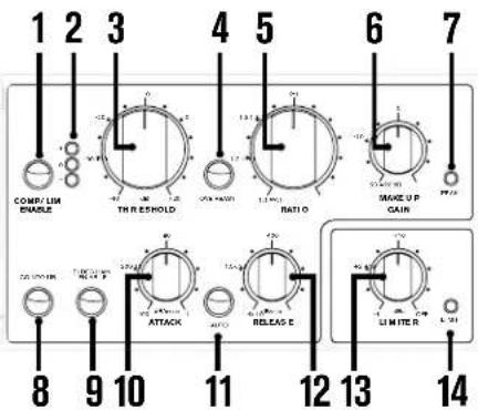
1. Comp/Lim Enable Button
Press this button to enable/disable the compressor and limiter – the compressor and limiter are enabled when the button's LED is lit.
2. Compression Threshold LED Meter
These three LEDs indicate the relationship between the input signal level and the compressor's threshold setting.
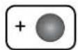
- When lit, the red '+' LED indicates that the signal level is above the currently set threshold and compression will be applied according to the RATIO control setting.

- When lit, the yellow 'O' LED indicates that the signal level is approaching the currently set threshold and is in the OverEasy™ region. Some minor compression will begin to be applied in this OverEasy region and full compression will be applied if the signal level does exceed threshold. Note that this LED only functions when the OVEREASY button is engaged.

- When lit, the green '-' LED indicates that the signal level is below the currently set threshold and no compression is being applied.
3. Threshold Control [-40 dB to +20 dB]
This control sets the level at which the compressor will begin compressing.
4. OverEasy Button
This button toggles the OverEasy feature on and off. When OverEasy is enabled, the compressor will act as a 'soft-knee' compressor, meaning that compression is applied more gradually as it approaches the threshold and is then fully compressed once the threshold is exceeded. This mode provides softer, more musical, and less obvious compression. When OverEasy is disabled, the compressor will act as a 'hard-knee' compressor, which is better suited when you want a more up-front and aggressive sound.
5. Ratio Control [1:1 to ∞:1]
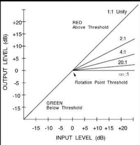
This control sets the amount of gain reduction applied when compression occurs. For example, when the ratio is set to 4:1, the output level will increase by only 1 dB for every 4 dB of signal level over the set threshold. So, using this example, if the signal level were to exceed the threshold by 8 dB, the increase in level post-compression would be only 2 dB – meaning 6 dB of gain reduction has been applied. Conversely, a ratio setting of 1:1 would yield no difference in input to output ratio, meaning no compression would be applied. Use lower settings for gentle compression and higher settings for heavier compression or limiting.
6. Makeup Gain Control [-20 dB to +20 dB]
This control adjusts the gain post-compression and pre-limiter. Generally, this control is used to make up for the amount of gain lost due to compression. This effectively increases lower-level portions of the signal so that they aren't 'lost in the mix' and allows you to better judge what the compressor is doing when comparing the compressed verses uncompressed signals.
One way to set this control is to simply look at the VU meter with the VU meter selection set to 'G.R.' (Gain Reduction) mode and set the MAKEUP GAIN control to the same value. For example, if the G.R. meter reads a maximum of -5 dB of gain reduction, you would set the MAKEUP GAIN control to 5 dB. A more precise method for setting the MAKEUP GAIN is to adjust the control as you audition the compression. To do this, A/B the compressed signal with the uncompressed signal using the COMP/LIM ENABLE button and set the MAKEUP GAIN control so that both signal levels match during song sections where the most compression is being applied.
7. Peak LED
This LED follows the meter selection made on the VU meter. If the INPUT VU meter option is selected, this LED will indicate when the circuit post the Preamp/EQ is approaching or has been driven into clipping. If the OUTPUT VU meter option is selected, this LED will indicate when the circuit post the Compressor/Limiter is approaching or has been driven into clipping. Note that the LED will begin to light around 3 dB before the onset of clipping. Also note that if the G.R. VU meter option is selected, this LED will become inactive. See 'Block Diagram' on page 23 for a visual representation of the locations in the signal path where this LED references the signal.
8. Contour Button
This button enables a high-pass filter at around 180 Hz in the compressor's detector circuit. This will gently roll off the lower frequencies and prevent them from triggering compression – this will not remove these lower frequencies from the audio signal. Enable this button to minimize 'pumping' or 'breathing' artifacts which can occur when attempting to apply heavier compression to signals with excessive energy in this lower-frequency region, such as a bass guitar, bass synth, or kick drum. When enabled, this feature allows for faster attack times and higher compression ratios with less artifacts.
9. Sidechain Enable Button
When this button is engaged, the signal will pass through the SIDECHAIN INSERT jack on the rear panel. Using the SIDECHAIN INSERT jack allows you to insert an external processor for altering the signal feeding the compressor's detection circuit. This can be used for frequency-weighted compression applications, such as de-essing, or for other creative sidechain compression techniques, see 'Sidechain Application' on page 21 for more information. Note that when nothing is connected to the SIDECHAIN connector, enabling this button will have no effect on the audio.
10. Attack Control [400 dB/msec - 1 dB/msec]
This control adjusts the amount of time it takes the compressor to react and begin compressing the signal. 400 dB/msec is the fastest attack setting. Theoretically, this means that it would take the compressor 1 millisecond to compress the signal by 400 dB. So when applying 10 dB of compression with an attack time setting of 400 dB/msec, the attack time would be 25 microseconds (400/10 = 40, 1 msec/40 = .025 milliseconds, which converts to 25 microseconds). Conversely, 1 dB/msec is the slowest attack setting. So if we use the previous example and apply 10 dB of compression using the slowest attack setting of 1 dB/msec, the attack time would be 10 milliseconds (1/10 = 0.1, 1 msec/0.1 = 10 milliseconds).
11. Auto Button
This button toggles the compressor's AUTO function on and off. When this button is disengaged, the compressor will react based on the ATTACK and RELEASE control settings. When this button is engaged, the compressor will automatically adjust the attack and release characteristics based on the incoming program signal and the ATTACK and RELEASE control settings will be ignored.
676
12. Release Control [4000 dB/sec - 10 dB/sec]
This control adjusts the amount of time it takes the compressor to recover from compression. 4000 dB/sec is the fastest release setting. Theoretically, this means that it would take the compressor 1 second to fully recover from 4000 dB of compression. So if 10 dB of compression were applied with a release time setting of 4000 dB/sec, the release time would be 2.5 milliseconds (4000/10 = 400, 1 sec/400 = .0025 seconds, which converts to 2.5 milliseconds). 10 dB/sec is the slowest release setting. If we use the previous example and apply 10 dB of compression using the slowest release setting of 10 dB/sec, the release time would be 1 second, which is obvious but here's the equation anyway (10/10 = 1, 1 sec/1 = 1 second).
13. Limiter Control [-4 dBu to OFF]
This control adjusts the limiter's threshold, or the level at which limiting will begin to occur. Turning this control fully clockwise will set the limiter threshold to the output clipping point of the 676, essentially turning the limiter off. Note that the limiter will also be bypassed when the COMP/LIM ENABLE button is disengaged. The further the LIMITER control is turned counter-clockwise, the lower the threshold will be.
This limiter is a dbx PeakPlus™ limiter and is designed to be used for level-critical applications, where you really want to clamp down on the program material. The LIMIT LED will indicate when this threshold is exceeded and limiting is occurring. The amount of gain reduction applied by the limiter can be seen in the VU meter when the G.R. METER SELECTION button is active.
HINT: When viewing gain reduction amount in the VU meter, the accumulative gain reduction applied by both the compressor and limiter will be displayed. To see only the gain reduction applied by limiting, you can temporarily disengage the compressor by setting the compressor's THRESHOLD control to the full clockwise position. Once the limiter gain reduction amount is verified in the VU meter, simply set the compressor's THRESHOLD control back to the original position. The same can be done with the LIMITER control to verify the amount of gain reduction applied by compression only.
14. Limit LED
This LED lights when the limiter's threshold has been exceeded and limiting is occurring.
Compressor/Limiter Example Settings
The below settings are designed to be used as a starting point. Your results using these settings will vary depending on the variables inherent in your application. For best results, adjust the settings to suit your application as described in the section following the below examples.
VOCALS ACOUSTIC GUITAR
Adjust for 2-5 dB of compression on G.R. meter.
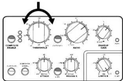
MIKED ELECTRIC GUITAR
Adjust for 2-5 dB of compression on G.R. meter.

Adjust for 2-5 dB of compression on G.R. meter.

DIRECT BASS GUITAR
Adjust for 2-5 dB of compression on G.R. meter.

Setting The Compressor/Limiter
- Start by setting all settings as shown below:
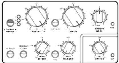
- While monitoring the source signal, lower the THRESHOLD control until the threshold meter begins bouncing back and forth between the green - and red + LEDs.
- Adjust the MAKEUP GAIN control so that you can adequately hear the signal you are processing.
- Raise the ATTACK control until the desired amount of attack is heard.
- Raise the RELEASE control until the compressor's release sounds musical in context of the song.
- Lower the RATIO control until the desired amount of compression is achieved.
- Adjust the MAKEUP GAIN control to match the amount of gain reduction being applied. Or audition the compressed vs. bypassed signals by toggling the COMP/LIM ENABLE button and set it so that the two signals are closely matched.
- If the signal is 'pumping' undesirably or you're recording an instrument with a lot of low-frequency energy, such as a bass guitar, try engaging the CONTOUR button. Toggle it off and on and select the position that sounds most appropriate for the application.
- Toggle the AUTO button on and off and select the position which provides the best results.
- If you want the compression to sound more subtle and natural, try engaging the OVEREASY button – this will soften the knee of the compressor. Note that this may also lower the output signal level, so you may have to adjust the MAKEUP GAIN control to compensate. If you determine that a hard-knee compressor suits the application better, leave the OVEREASY button disengaged.
- If you would like to also limit the signal, slowly lower the LIMITER control until the LIMIT LED begins to light occasionally. If you wish to use only the limiter, set the compressor's RATIO control to 1:1. This will prevent the compressor from activating and allow only the limiter to be used.
Parallel Compression
Compression is typically applied as a serial process – meaning the entire signal is processed by the compressor. This is sometimes referred to as 'downward compression'. By applying make-up gain, the compressed signal can then be raised to restore the signal's average level to what it was before applying compression, hence the term 'make-up gain'. Raising the make-up gain also raises signal levels which reside below the compressor's threshold, effectively raising lower-level portions of the program signal and making them more audible in the mix. Using compression in this manner is very effective for most applications, but there are times you may want the compression to be less obvious or you don't want to trample on the original transients and tone of the source, but still want to raise the lower-level portions of the signal. This is where the stealthier parallel compression comes in.
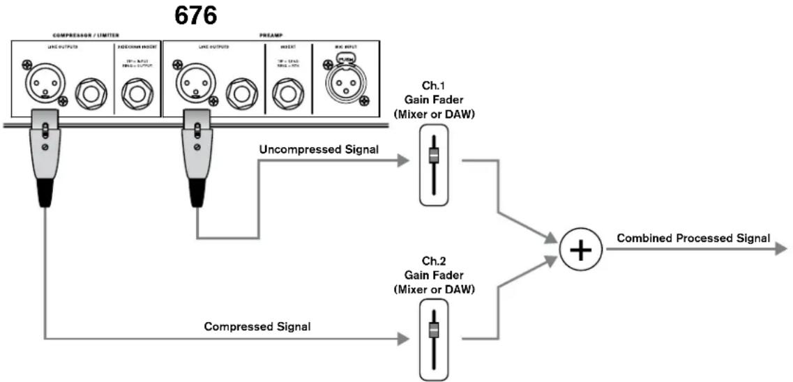
Reverb and delay effects are generally applied as a parallel effect (more commonly known as a 'send/return' effect, or simply 'send' effect) – meaning that the signal is split, one signal is processed, then the processed signal is mixed back in with the unprocessed signal. Parallel compression works the same way – the signal is split, one signal is compressed, then the compressed signal is mixed back in with the uncompressed signal (see below diagram).
Parallel compression is a very common technique used in today's audio production. It is a particularly popular technique for drums, vocals, and acoustic guitar, but it can be used on anything. When applying parallel compression, the idea is to have the compressed version of the signal disappear into the background as full compression is applied (typically 20 dB or more) – this leaves the original sound virtually unchanged as the compressed signal is reduced below the point of audibility. When the program signal level falls back below threshold, the severely compressed signal will begin to raise in level as the compressor releases. This allows the lower-level detail in the program signal to be raised without compromising the tone and transients of the original sound. This technique is also commonly used with more characterful compressors (this is very common on drums and vocals and is commonly known as the 'New York Compression Trick').
The 676 has two outputs which can be used simultaneously to provide parallel compression capabilities. These two outputs are the PREAMP and COMPRESSOR / LIMITER outputs. The COMPRESSOR / LIMITER output carries the signal post the compressor/limiter processing. The PREAMP output carries the signal post EQ and before the compressor/limiter processing. By using both outputs simultaneously, you can compress the signal coming out of the COMPRESSOR / LIMITER output and recombine it with the uncompressed signal coming from the PREAMP output at the mixer or DAW as shown in the below diagram.
PARALLEL COMPRESSION DIAGRAM
flowchart
graph TD
    A["COMPRESSION / LIMITER"] --> B["LINE OUTPUTS"]
    A --> C["FLOOD/MAN INDEX"]
    A --> D["LIME OUTPUTS"]
    A --> E["MREFLECT"]
    A --> F["RWD INPUT"]
    B --> G["Compressed Signal"]
    C --> H["Compressed Signal"]
    D --> I["Uncompressed Signal"]
    E --> I
    F --> J["Combined Processed Signal"]
    G --> K["Ch.1 Gain Fader (Mixer or DAW)"]
    H --> L["Ch.2 Gain Fader (Mixer or DAW)"]
    I --> M["+"]
    J --> M
Application Guide
Direct Instrument Recording Application
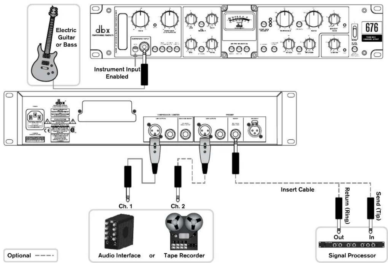
Use this configuration to record the direct signal from an electric guitar or bass using the 676's Hi-Z INSTRUMENT INPUT. In this configuration the direct signal will still pass through the tube gain stage, making it great for recording harmonically-rich bass and guitar tracks!
Application Notes:
- The INSTRUMENT INPUT must be enabled on the front panel using the button located next to the jack.
- Either the PREAMP output, COMPRESSOR / LIMITER output, or both outputs can be used in this application. Use the COMPRESSOR / LIMITER output if you wish to process the signal with the 676's built-in compressor and/or limiter. When using the compressor/limiter, use both jacks to have a backup of the uncompressed signal, for parallel compression applications, or for recording the uncompressed version and sending the compressed version to the musician's headphone mix.
- A signal processor can be inserted in the PREAMP INSERT. Here you can connect a favorite compressor, EQ, or any other signal processor you wish to insert after the preamp.
Mic Preamp Application
Use this configuration for recording vocals or an acoustic instrument using a microphone. It is also applicable for live sound use when connecting a mic or direct instrument signal using a D.I. box located on-stage.
Application Notes:
- The INSTRUMENT INPUT must be disabled on the front panel using the button located next to the jack.
- Engage the +48V button if connecting a condenser microphone or active D.I. box which requires it. Disengage the +48V button for any microphones which don't require phantom power, such as a dynamic or ribbon microphone.
- Either the PREAMP output, COMPRESSOR / LIMITER output, or both outputs can be used in this application. Use the COMPRESSOR / LIMITER output if you wish to process the signal with the 676's built-in compressor and/or limiter. When using the compressor/limiter, use both jacks to have a backup of the uncompressed signal, for parallel compression applications, or for recording the uncompressed version and sending the compressed version to the musician's headphone mix.
- A signal processor can be inserted in the PREAMP INSERT. Here you can connect a favorite compressor, EQ, or any other signal processor you wish to insert after the preamp.

Sidechain Application
Use this configuration to use the 676's built-in compressor as a de-esser. De-essing is typically used to reduce the level of 'sibilant' frequencies in vocals, which can make them sound abrasive and unpleasant. Excess sibilance can be caused by compression, mic selection and/or placement, or by the vocalist's technique. The sibilant range of frequencies is typically located between around 2-10kHz, depending on the vocalist.
De-essing is a form of frequency-weighted compression. In the 676, it is accomplished by patching an external EQ into the compressor's SIDECHAIN INSERT jack. Boosting frequency bands on the external EQ will then increase the amplitude of the selected range of frequencies making the compressor react to them before other frequencies.
Application Notes:
- The COMPRESSOR / LIMITER output will carry the 'de-essed' signal. However, you can also connect the PREAMP output and send its signal to another input or track if you wish to have a version of the unprocessed signal for backup.
- Note that connecting the SIDECHAIN INSERT jack to a normalled patchbay allows for additional creative sidechaining capabilities (for example, for triggering compression on the bass guitar every time the kick drum hits), see “Using The 676 EQ & Compressor At Mixdown” on page 22 for additional information on connecting the SIDECHAIN INSERT to a patchbay.

Using The 676 EQ & Compressor At Mixdown
It is possible to use the 676 EQ and compressor during the mixing stage if your audio interface has a spare line output, available line input, and decent-quality A/D and D/A converters. This allows you to non-destructively apply EQ and compression to tracks by processing them one at a time and printing them back into your Digital Audio Workstation (DAW) to new tracks. Due to the inherent latency involved in this round trip, you will need to time align the newly printed tracks with the original inside your DAW's editor. If you plan to use the 676's compressor and/or EQ to process only a single track during the mixing stage, you can process the track in real time if your DAW allows you to compensate for the latency invoked by the external processing. Note that the signal will bypass the 676's preamp tube stage when used in this manner, so the INPUT GAIN and POST TUBE ATTENUATION controls will have no affect. Therefore, the output level from your DAW should be adjusted to optimize the signal level feeding the 676 for the best noise and processing performance.
Application Notes:
- This application requires that a normalled patch bay, such as the dbx PB-48, be used. This allows the PREAMP INSERT to still function normally as a standard insert and regular operation to be maintained when no connection is made to the front jacks of the patchbay (see below diagram). Note that this same patchbay connection configuration can also be used for the compressor SIDECHAIN INSERT jack. This allows for easy patching as well as sidechaining of the compressor from another source.
- Connect the COMPRESSOR / LIMITER output to a line input on your audio interface.

flowchart
graph TD
    A["DBX"] --> B["Compressor / Limiter"]
    B --> C["TRS (Tip-Ring-Sleeve)"]
    C --> D["Insert Cable"]
    D --> E["Normalled Patch Bay"]
    E --> F["Signal Flow"]
    F --> G["Return (Ring)"]
    G --> H["Rear"]
    H --> I["Front"]
    I --> J["Output"]
    K["Audio Interface"] --> L["OutIn"]
    L --> M["Unbalanced TS Cable"]
Technical Information
Block Diagram
* Note that if the G.R. VU meter option is selected, the VU meter will display gain reduction applied due to compression/limiting and the Peak LED will become inactive.

flowchart
graph TD
    A["Input Peak LED"] --> B["676 Audio Path"]
    B --> C["Preamp Output"]
    C --> D["Preamp Inser"]
    D --> E["Send/Return"]
    E --> F["Comparator Detector"]
    F --> G["Comparator Inverter"]
    G --> H["Comparator Outlet"]
    H --> I["Sided Chain Inser"]
    I --> J["In/Out In"]
    C --> K["Preamp Output"]
    K --> L["Preamp Inser"]
    L --> M["Output VU Monitor Button Enaged"]
    M --> N["*VU Meter Peak LED"]
    N --> O["Output VU Monitor Button Enaged"]
    O --> P["*VU Meter"]
    P --> Q["Output VU Monitor Button Enaged"]
    Q --> R["Output VU Monitor Button Enaged"]
    R --> S["Output VU Monitor Button Enaged"]
    S --> T["Output VU Monitor Button Enaged"]
    T --> U["Output VU Monitor Button Enaged"]
    U --> V["Output VU Monitor Button Enaged"]
    V --> W["Output VU Monitor Button Enaged"]
    W --> X["Output VU Monitor Button Enaged"]
    X --> Y["Output VU Monitor Button Enaged"]
    Y --> Z["Output VU Monitor Button Enaged"]
    Z --> AA["Output VU Monitor Button Enaged"]
    AA --> AB["Output VU Monitor Button Enaged"]
    AB --> AC["Output VU Monitor Button Enaged"]
    AC --> AD["Output VU Monitor Button Enaged"]
    AD --> AE["Output VU Monitor Button Enaged"]
    AE --> AF["Output VU Monitor Button Enaged"]
    AF --> AG["Output VU Monitor Button Enaged"]
    AG --> AH["Output VU Monitor Button Enaged"]
    AH --> AI["Output VU Monitor Button Enaged"]
    AI --> AJ["Output VU Monitor Button Enaged"]
    AJ --> AK["Output VU Monitor Button Enaged"]
    AK --> AL["Output VU Monitor Button Enaged"]
    AL --> AM["Output VU Monitor Button Enaged"]
    AM --> AN["Output VU Monitor Button Enaged"]
    AN --> AO["Output VU Monitor Button Enaged"]
    AO --> AP["Output VU Monitor Button Enaged"]
    AP --> AQ["Output VU Monitor Button Enaged"]
    AQ --> AR["Output VU Monitor Button Enaged"]
    AR --> AS["Output VU Monitor Button Enaged"]
    AS --> AT["Output VU Monitor Button Enaged"]
    AT --> AU["Output VU Monitor Button Enaged"]
    AU --> AV["Output VU Monitor Button Enaged"]
    AV --> AW["Output VU Monitor Button Enaged"]
    AW --> AX["Output VU Monitor Button Enaged"]
    AX --> AY["Output VU Monitor Button Enaged"]
    AY --> AZ["Output VU Monitor Button Enaged"]
    AZ --> BA["Output VU Monitor Button Enaged"]
    BA --> BB["Output VU Monitor Button Enaged"]
    BB --> BC["Output VU Monitor Button Enaged"]
    BC --> BD["Output VU Monitor Button Enaged"]
    BD --> BE["Output VU Monitor Button Enaged"]
    BE --> BF["Output VU Monitor Button Enaged"]
    BF --> BG["Output VU Monitor Button Enaged"]
    BG --> BH["Output VU Monitor Button Enaged"]
    BH --> BI["Output VU Monitor Button Enaged"]
    BI --> BJ["Output VU Monitor Button Enaged"]
    BJ --> BK["Output VU Monitor Button Enaged"]
    BK --> BL["Output VU Monitor Button Enaged"]
    BL --> BM["Output VU Monitor Button Enaged"]
    BM --> BN["Output VU Monitor Button Enaged"]
    BN --> BO["Output VU Monitor Button Enaged"]
    BO --> BP["Output VU Monitor Button Enaged"]
    BP --> BQ["Output VU Monitor Button Enaged"]
    BQ --> BR["Output VU Monitor Button Enaged"]
    BR --> BS["Output VU Monitor Button Enaged"]
    BS --> BT["Output VU Monitor Button Enaged"]
    BT --> BU["Output VU Monitor Button Enaged"]
    BU --> BV["Output VU Monitor Button Enaged"]
    BV --> BW["Output VU Monitor Button Enaged"]
    BW --> BX["Output VU Monitor Button Enaged"]
    BX --> BY["Output VU Monitor Button Enaged"]
    BY --> BZ["Output VU Monitor Button Enaged"]
    BZ --> CA["Output VU Monitor Button Enaged"]
    CA --> CB["Output VU Monitor Button Enaged"]
    CB --> CC["Output VU Monitor Button Enaged"]
    CC --> CD["Output VU Monitor Button Enaged"]
    CD --> CE["Output VU Monitor Button Enaged"]
    CE --> CF["Output VU Monitor Button Enaged"]
    CF --> CG["Output VU Monitor Button Enaged"]
    CG --> CH["Output VU Monitor Button Enaged"]
Compression Graphs
Ratio OverEasy

line
| INPUT LEVEL (dB) | OUTPUT LEVEL (dB) for 1:1 | OUTPUT LEVEL (dB) for 2:1 | OUTPUT LEVEL (dB) for 4:1 | OUTPUT LEVEL (dB) for ∞:1 | | ---------------- | -------------------------- | -------------------------- | -------------------------- | -------------------------- | | -15 | -15 | -15 | -15 | -15 | | -10 | -10 | -10 | -10 | -10 | | -5 | -5 | -5 | -5 | -5 | | 0 | 0 | 0 | 0 | 0 | | 5 | 5 | 5 | 5 | 5 | | 10 | 10 | 10 | 10 | 10 | | 15 | 15 | 15 | 15 | 15 | | 20 | 20 | 20 | 20 | 20 |Off OverEasy
line
| INPUT LEVEL (dB) | OUTPUT LEVEL (dB) | | ---------------- | ----------------- | | -15 | -15 | | -10 | -10 | | -5 | -5 | | 0 | 0 | | 5 | 5 | | 10 | 10 | | 15 | 15 | | 20 | 20 |® On

line
| INPUT LEVEL (dB) | OUTPUT LEVEL (dB) | | ---------------- | ----------------- | | -15 | -15 | | -10 | -10 | | -5 | -5 | | 0 | 0 | | 5 | 5 | | 10 | 10 | | 15 | 15 | | 20 | 20 |EQ Plot
Audio Cable Diagrams
FROM SOURCE DEVICE (OUTPUT) TO NEXT DEVICE (INPUT) FEMALE XLR TO TRS PHONE FEMALE XLR TO TRS PHONE | FROM SOURCE DEVICE (OUTPUT) TO NEXT DEVICE (INPUT) TRS PHONE TO MALE XLR TRS PHONE TO MALE XLR |
| FROM SOURCE DEVICE (OUTPUT) TO NEXT DEVICE (INPUT)[HOT +]TRS PHONE TO TRS PHONE | FROM SOURCE DEVICE (OUTPUT) TO NEXT DEVICE (INPUT) FEMALE XLR TO MALE XLR FEMALE XLR TO MALE XLR |
FROM SOURCE DEVICE (OUTPUT) TO NEXT DEVICE (INPUT) TS PHONE TO MALE XLR TS PHONE TO MALE XLR | FROM SOURCE DEVICE (OUTPUT) TO NEXT DEVICE (INPUT) TS PHONE TO TRS PHONE TS PHONE TO TRS PHONE |
FROM SOURCE DEVICE (OUTPUT) TO NEXT DEVICE (INPUT) RCA PHONO TO MALE XLR RCA PHONO TO MALE XLR | FROM SOURCE DEVICE (OUTPUT) TO NEXT DEVICE (INPUT) RCA PHONO TO TRS PHONE RCA PHONO TO TRS PHONE |
FROM SOURCE DEVICE (OUTPUT) TO NEXT DEVICE (INPUT) TS PHONE TO TS PHONE TS PHONE TO TS PHONE | FROM SOURCE DEVICE (OUTPUT) TO NEXT DEVICE (INPUT) RCA PHONO TO TS PHONE RCA PHONO TO TS PHONE |
FROM SOURCE DEVICE (OUTPUT) TO NEXT DEVICE (INPUT) TRS PHONE TO TS PHONE TRS PHONE TO TS PHONE | FROM SOURCE DEVICE (OUTPUT) TO NEXT DEVICE (INPUT) TS PHONE TO RCA PHONO TS PHONE TO RCA PHONO |
FROM SOURCE DEVICE (OUTPUT) TO NEXT DEVICE (INPUT)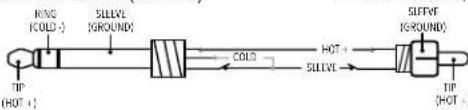 TRS PHONE TO RCA PHONO TRS PHONE TO RCA PHONO |  |
Replacing The Tube
INSTRUCTIONS FOR QUALIFIED SERVICE PERSONNEL:

CAUTION! These servicing instructions are for use by qualified service personnel only. To reduce the risk of electric shock, do not perform any servicing other than that contained in the operating instructions unless you are qualified to do so. Refer all servicing to qualified service personnel. Disconnect mains power before servicing.

The 676 ships with a 12AU7 dual triode vacuum tube. Although other tube types, such as the 12AX7 and 12AT7, will work in the 676, be aware that they will change the saturation characteristics of the preamp. Various manufacturers make these types of tubes and each will impart different tonal and sonic qualities. Although the 676 ships with a tube that suits various applications well, finding a tube that imparts the qualities which best suit your taste can make the 676 an even more valuable tool.
To change the tube:
- Disconnect the power cord from the 676.
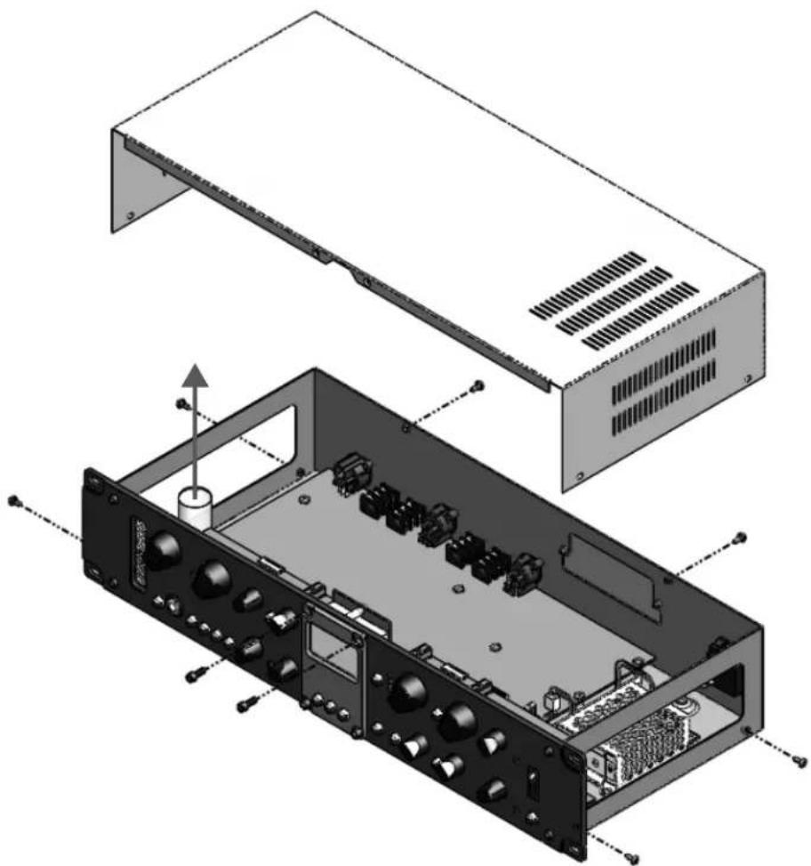
- Remove the 8 lid screws as shown in the illustration to the right – the 2 center screws in the front panel require an Allen (hex) key and all remaining screws require a Phillips screwdriver.
- Lift the lid straight up and off the chassis.
- With the 676 chassis held securely, carefully pull the tube straight up and out of the socket.
- Line up the replacement tube's pins with the socket then insert the tube, being careful to push it straight in to avoid bending the pins.
- Re-attach the lid, making sure the lid is properly oriented and the Allen screws are inserted into the front panel.
natural_image
Exploded view diagram of an electronic device showing internal components and casing (no text or labels)Replacing The Fuse
The power fuse is located in the drawer at the bottom of the IEC power inlet on the back panel of the 676. From the factory, there will be two fuses in this drawer. The fuse located in the rear drawer position is the one currently being used in the circuit. The fuse located in the front drawer position is the provided spare fuse.
Insert small flat-head screwdriver behind tab and gently pry open.
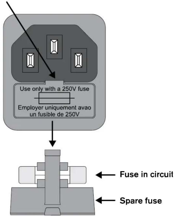
WARNING! Replace with same type fuse only (T2.5AL 250V).
Specifications
MICROPHONE INPUT
Connector: Female XLR (Pin 2 Hot)
Type: Transformer balanced/unbalanced, RF filtered
Impedance: 1.9 kΩ
CMRR: >85 dB from 20 Hz to 3 kHz, >70 dB from 3 kHz to 20 kHz
INSTRUMENT INPUT (FRONT PANEL)
Connector: Tip-Sleeve 1/4" Jack
Type: Unbalanced
Impedance: 500 kΩ
Maximum Input Level: +21 dBu unbalanced
PREAMP INSERT
Connector: Tip-Ring-Sleeve 1/4", RF filtered
Type: Unbalanced, Tip = send, Ring = return
Impedance: 50 Ω (send), 20 kΩ (return)
LINE OUTPUTS (PREAMP & COMPRESSOR/LIMITER)
Connector: Male XLR and Tip-Ring-Sleeve 1/4" (Pin 2 and Tip hot)
Type: Servo-balanced/unbalanced
Impedance: Balanced 30 Ω, unbalanced 15 Ω
Maximum Output Level: >+21 dBm (into a 600 ohm load)
COMPRESSOR SIDECHAIN INSERT
Connector: Tip-Ring-Sleeve 1/4", RF filtered
Type: Unbalanced, Ring = output, Tip = input
Impedance: 1 kΩ (output), 50 kΩ (input)
VACUUM TUBE
Type: 12AU7A / ECC82
Grid Power Supply: +250V DC
Heater Power Supply: +12V DC
SYSTEM PERFORMANCE
Frequency Response: Mic Input: 20 Hz to 50 kHz, +0/-1dB, 40 dB gain
Instrument Input: 30 Hz to 70 kHz, +0/-1dB, unity gain
THD + Noise: Mic In to Line Out: 0.25% typical at 0 dBu out, 1 kHz, 40 dB gain
Instrument In to Line Out: 0.2% typical at 0 dBu out, 1kHz, unity gain
Equivalent Input Noise: Typically > -123 dBu with a 150 Ω source load, 22 Hz to 22 kHz
Noise Floor: Mic Insert to Comp Output: <-93 dBu, unity gain, EQ flat and no gain reduction
Operating Temperature: 0^ to 40^ C ( 32^ to 104^ F)
PREAMP FUNCTION SWITCHES / CONTROLS
Instrument Input: Selects between microphone XLR input and front panel 1/4" instrument input
+48V: Sends +48 VDC through 6.81 kΩ resistors to pins 2 and 3 of the microphone input
20 dB PAD: Attenuates the microphone input by 20 dB
Polarity Invert: Reverses pins 2 and 3 of the microphone input XLR
80 Hz Low Cut: Enables an 80 Hz, 12 dB/octave high-pass filter in the microphone and instrument signal path
GAIN Control Range: -∞ to +55 dB for Microphone Input
-∞ to +40 dB for Instrument Input
Post Tube Attenuation: - to 0 dB
Peak Indicator: Illuminates RED when the Preamp is within 3 dB of clipping
676
EQUALIZER
LOW Frequency: 100 Hz, Low-pass shelving filter
HIGH Frequency: 10 kHz, High-pass shelving filter
MID Frequency: Sweepable from 100 Hz to 8 kHz
NARROW: Selects the "Q" of the MID Frequency EQ. "OUT" position Q = 0.9; "IN" position Q = 2.9
Gain (All Bands): Sweepable from -15 to +15 dB
COMPRESSOR
Threshold Range: -40 dBu to +20 dBu
Threshold Characteristic: Selectable OverEasy™ or Hard Knee
Compression Ratio: Variable 1:1 to ∞:1; 60 dB maximum Compression
Attack/Release Modes: Selectable Manual or Auto
Manual Attack Time: Scalable program-dependent; Typically 400 dB/msec to 1 dB/msec
Manual Release Time: Scalable program-dependent; Typically 4000 dB/sec to 10 dB/sec
Auto Attack Time: Program-dependent, typically 15 ms for 10 dB, 5 ms for 20 dB, 3 ms for 30 dB
Auto Release Time: Program-dependent, typically 120 dB/sec
Output Level Control Range: -20 dB to +20 dB
Peak Indicator: Illuminates RED when the Compressor/Limiter is within 3 dB of clipping
LIMITER
Type: dbx PeakPlus™
Threshold Range: -4 dBu to + 22 dBu (off)
Ratio: :1
Attack and Release: Program-dependent
POWER SUPPLY
Type: Universal switch-mode
Operating Voltage: 100 - 240 VAC, 50/60 Hz
Power Requirements: 20 Watts
Fuse: T2.5AL 250V
Turn-On Time: Approximately 2 seconds
PHYSICAL
Dimensions: 3.5"H X 19"W X 8"D
Weight: 8.1 lbs (3.7 kg)
Shipping Weight: 11.0 lbs (5.0 kg)
Note: 0dBu = 0.775V RMS
Specifications are subject to change without notice.
All Trademarks and Registered Trademarks are the property of their respective owners.

NOTES:
dbx®
by HARMAN
Phone: (801) 566-8800
Website: dbxpro.com
Support: dbxpro.com/en-US/support
dbx Professional Products
is a registered trademark of Harman
676 Owner's Manual
PN: 5058151-C
© 2016 Harman
All rights reserved


- Technical Support & Service
- Table of Contents
- Overview 2
- Installation 4
- Quick Start 5
- The User Interface & Connectors 6
- The Preamp Section 8
- The EQ Section 10
- The Compressor & Limiter Section ......12
- Application Guide 19
- Technical Information 23
- Recall Sheet 30
- Overview
- Introduction
- 676
- Features
- Installation
- Installation Recommendations
- Making Connections
- Applying Power
- Quick Start
- The User Interface & Connectors
- Preamp
- EQ
- Meter
- Compressor
- Power Switch
- Meter Selection Buttons
- Limiter
- Rear Panel
- Power Connector
- Fuse Drawer
- Compressor/Limiter Line Output Connectors
- Compressor Sidechain Insert Connector
- Preamp Line Output Connectors
- Preamp Insert Connector
- Mic Input Connector
- The Preamp Section
- Gain Control
- Peak LED
- Post Tube Attenuation Control
- Instrument Input Enable Button
- Instrument Input Connector
- +48V Button
- 20dB Pad Button
- Polarity Invert Button
- 80 Hz Low Cut Button
- Preamp Example Settings
- Setting The Preamp
- The EQ Section
- EQ Example Settings
- Setting The EQ
- The Compressor & Limiter Section
- Comp/Lim Enable Button
- Compression Threshold LED Meter
- Threshold Control [-40 dB to +20 dB]
- OverEasy Button
- Ratio Control [1:1 to ∞:1]
- Makeup Gain Control [-20 dB to +20 dB]
- Peak LED
- Contour Button
- Sidechain Enable Button
- Attack Control [400 dB/msec - 1 dB/msec]
- Auto Button
- Release Control [4000 dB/sec - 10 dB/sec]
- Limiter Control [-4 dBu to OFF]
- Limit LED
- Compressor/Limiter Example Settings
- Setting The Compressor/Limiter
- Parallel Compression
- Application Guide
- Direct Instrument Recording Application
- Application Notes:
- Mic Preamp Application
- Sidechain Application
- Using The 676 EQ & Compressor At Mixdown
- Technical Information
- Block Diagram
- Compression Graphs
- EQ Plot
- Audio Cable Diagrams
- Replacing The Tube
- To change the tube:
- Replacing The Fuse
- Specifications
- MICROPHONE INPUT
- INSTRUMENT INPUT (FRONT PANEL)
- PREAMP INSERT
- LINE OUTPUTS (PREAMP & COMPRESSOR/LIMITER)
- COMPRESSOR SIDECHAIN INSERT
- VACUUM TUBE
- SYSTEM PERFORMANCE
- PREAMP FUNCTION SWITCHES / CONTROLS
- EQUALIZER
- COMPRESSOR
- LIMITER
- POWER SUPPLY
- PHYSICAL
- dbx®
- by HARMAN
Brand : DBX
Model : 676
Category : Receiver