
ProVocal - Receiver DBX - Free user manual and instructions
Find the device manual for free ProVocal DBX in PDF.


| Product Type | Digital Vocal Processor |
| Dimensions (H x D x W) | 1.75 x 5.75 x 19 inches (44.45 x 146.05 x 482.6 mm) |
| Weight | 7.14 lb (3.24 kg) |
| Power Supply | 100-240 VAC, 50/60 Hz, 15 W |
| Microphone Input | Female XLR, balanced, 330 Ω, +30 to +60 dB gain, +48V phantom power, 20 dB pad |
| Line Input (Rear) | 1/4" TRS, balanced, 20 kΩ (unbalanced), -15 to +15 dB gain |
| Instrument Input (Front) | 1/4" TS, unbalanced, 470 kΩ, -15 to +15 dB gain |
| Analog Outputs | XLR and 1/4" TRS, balanced, 120 Ω, max +18 dBu |
| Digital Output | RCA S/PDIF, 75 Ω, 24-bit, selectable 44.1 or 48 kHz |
| Frequency Response | 20 Hz – 20 kHz, +0/-0.5 dB |
| Dynamic Range (A/D) | 105 dB A-weighted, 102 dB unweighted |
| Dynamic Range (D/A) | 103 dB A-weighted, 101 dB unweighted |
| THD+Noise | 0.002% typical at +4 dBu |
| Effects Modules | Compression, De-Esser/Gate, Chorus/Flanger, Delay/Reverb |
| Modeling | Microphone (19 models) and Preamp (9 models) with Drive and Gain control |
| EQ | 3-band parametric: Low ±12 dB @ 80 Hz, Mid with variable frequency/Q, High ±12 dB @ 12 kHz |
| MIDI Control | MIDI In, assignable CC parameters |
| Programs | 80 total (40 factory + 40 user) |
| Rack Mount | 1U, rack screws included |
| Safety Compliance | IEC 60065, EN 55013, EN 55020; CE marked |
| Battery | Lithium CR2032 (backup) |
Frequently Asked Questions - ProVocal DBX
User questions about ProVocal DBX
0 question about this device. Answer the ones you know or ask your own.
Ask a new question about this device
Download the instructions for your Receiver in PDF format for free! Find your manual ProVocal - DBX and take your electronic device back in hand. On this page are published all the documents necessary for the use of your device. ProVocal by DBX.
USER MANUAL ProVocal DBX
natural_image
Front panel of a ProVocal Digital Voice Transceiver (no visible text or symbols on the device body)IMPORTANT SAFETY INSTRUCTIONS
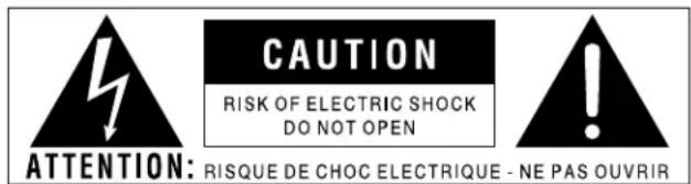
WARNING: TO REDUCE THE RISK OF FIRE OR ELECTRIC SHOCK DO NOT EXPOSE THIS EQUIPMENT TO RAIN OR MOISTURE
The symbols shown above are internationally accepted symbols that warn of potential hazards with electrical products. The lightning flash with arrowpoint in an equilateral triangle means that there are dangerous voltages present within the unit. The exclamation point in an equilateral triangle indicates that it is necessary for the user to refer to the owner's manual.
These symbols warn that there are no user serviceable parts inside the unit. Do not open the unit. Do not attempt to service the unit yourself. Refer all servicing to qualified personnel. Opening the chassis for any reason will void the manufacturer's warranty. Do not get the unit wet. If liquid is spilled on the unit, shut it off immediately and take it to a dealer for service. Disconnect the unit during storms to prevent damage.
SAFETY INSTRUCTIONS
NOTICE FOR CUSTOMERS IF YOUR UNIT IS EQUIPPED WITH A POWER CORD.
WARNING: THIS APPLIANCE MUST BE EARTHED.
The cores in the mains lead are coloured in accordance with the following code:
GREEN and YELLOW - Earth BLUE - Neutral BROWN - Live
As colours of the cores in the mains lead of this appliance may not correspond with the coloured markings identifying the terminals in your plug, proceed as follows:
- The core which is coloured green and yellow must be connected to the terminal in the plug marked with the letter E, or with the earth symbol, or coloured green, or green and yellow.
- The core which is coloured blue must be connected to the terminal marked N or coloured black.
- The core which is coloured brown must be connected to the terminal marked L or coloured red.
This equipment may require the use of a different line cord, attachment plug, or both, depending on the available power source at installation. If the attachment plug needs to be changed, refer servicing to qualified service personnel who should refer to the table below. The green/yellow wire shall be connected directly to the units chassis.
| CONDUCTOR | WIRE COLOR | ||
| Normal Alt | |||
| L | LIVE | BROWN | BLACK |
| N | NEUTRAL | BLUE | WHITE |
| E | EARTH GND | GREEN/YEL | GREEN |
WARNING: If the ground is defeated, certain fault conditions in the unit or in the system to which it is connected can result in full line voltage between chassis and earth ground. Severe injury or death can then result if the chassis and earth ground are touched simultaneously.
WARNING FOR YOUR PROTECTION PLEASE READ THE FOLLOWING:
KEEP THESE INSTRUCTIONS
HEED ALL WARNINGS
FOLLOW ALL INSTRUCTIONS
DO NOT USE THIS APPARATUS NEAR WATER
CLEAN ONLY WITH A DRY CLOTH.
DO NOT BLOCK ANY OF THE VENTILATION OPENINGS. INSTALL IN ACCORDANCE WITH THE MANUFACTURER'S INSTRUCTIONS.
DO NOT INSTALL NEAR ANY HEAT SOURCES SUCH AS RADIATORS, HEAT REGISTERS, STOVES, OR OTHER APPARATUS (INCLUDING AMPLIFIERS) THAT PRODUCE HEAT.
ONLY USE ATTACHMENTS/ACCESSORIES SPECIFIED BY THE MANUFACTURER.
UNPLUG THIS APPARATUS DURING LIGHTNING STORMS OR WHEN UNUSED FOR LONG PERIODS OF TIME.
Do not defeat the safety purpose of the polarized or grounding-type plug. A polarized plug has two blades with one wider than the other. A grounding type plug has two blades and a third grounding prong. The wide blade or third prong are provided for your safety. If the provided plug does not fit your outlet, consult an electrician for replacement of the obsolete outlet.
Protect the power cord from being walked on or pinched particularly at plugs, convenience receptacles, and the point where they exit from the apparatus.
Use only with the cart stand, tripod bracket, or table specified by the manufacture, or sold with the apparatus. When a cart is used, use caution when moving the cart/apparatus combination to avoid injury from tip-over.

Refer all servicing to to qualified service personnel. Servicing is required when the apparatus has been damaged in any way, such as power-supply cord or plug is damaged, liquid has been spilled or objects have fallen into the apparatus, the apparatus has been exposed to rain or moisture, does not operate normally, or has been dropped.
POWER ON/OFF SWITCH: The Power switch used in this piece of equipment DOES NOT break the connection from the mains.
ALL-POLE MAINS SWITCH: An all-pole mains switch with a contact separation of at least 3mm in each pole shall be incorporated in the electrical installation of the rack or building.
FOR UNITS EQUIPPED WITH EXTERNALLY ACCESSIBLE FUSE RECEPTACLE: Replace fuse with same type and rating only.
MULTIPLE-INPUT VOLTAGE: This equipment may require the use of a different line cord, attachment plug, or both, depending on the available power source at installation. Connect this equipment only to the power source indicated on the equipment rear panel. To reduce the risk of fire or electric shock, refer servicing to qualified service personnel or equivalent.
This Equipment is intended for rack mount use only.
IMPORTANT SAFETY INSTRUCTIONS
LITHIUM BATTERY WARNING
CAUTION!
This product may contain a lithium battery. There is danger of explosion if the battery is incorrectly replaced. Replace only with an Eveready CR 2032 or equivalent. Make sure the battery is installed with the correct polarity. Discard used batteries according to manufacturer's instructions.
ADVARSEL!
This unit conforms to the Product Specifications noted on the Declaration of Conformity. Operation is subject to the following two conditions:
- this device may not cause harmful interference, and
- this device must accept any interference received, including interference that may cause undesired operation.
Operation of this unit within significant electromagnetic fields should be avoided.
- use only shielded interconnecting cables.
U.K. MAINS PLUG WARNING
A molded mains plug that has been cut off from the cord is unsafe. Discard the mains plug at a suitable disposal facility. NEVER UNDER ANY CIRCUMSTANCES SHOULD YOU INSERT A DAMAGED OR CUT MAINS PLUG INTO A 13 AMP POWER SOCKET. Do not use the mains plug without the fuse cover in place. Replacement fuse covers can be obtained from your local retailer. Replacement fuses are 13 amps and MUST be ASTA approved to BS1362.
DECLARATION OF CONFORMITY
Manufacturer's Name: dbx Professional Products
Manufacturer's Address: 8760 S. Sandy Parkway
Sandy, Utah 84070, USA
declares that the product:
Product name: dbx ProVocal
Note: Product name may be suffixed by the letters -EU.
Product option: none
conforms to the following Product Specifications:
Safety:
IEC 60065 (1998)
EMC:
EN 55013 (1990)
EN 55020 (1991)
Supplementary Information:
The product herewith complies with the requirements of the Low Voltage Directive 72/23/EEC and the EMC Directive 89/336/EEC as amended by Directive 93/68/EEC.
dbx Professional Products
President of The Harman Music Group
8760 S. Sandy Parkway
Sandy, Utah 84070, USA
September 25, 2001
European Contact:
Your local dbx Sales and Service Office
or Harman Music Group
8760 South Sandy Parkway
Sandy, Utah 84070 USA
Ph: (801) 566-8800
Fax:(801) 568-7583
Introduction
0.1 Defining the ProVocal......i
0.2 Service Contact Info....ii
0.3 Warranty....ii
0.4 Installation Recommendations......iii
Section 1 - Getting Started
1.1 Rear Panel Connections....2
1.2 Front Panel Connections....3
Section 2 - Detailed Parameters/
Basic Operation and Utility
Functions
2.1 Detailed Parameters ....6
2.2 Basic Operation....9
2.3 Utility Functions ....11
2.4 Program List....12
Section 3 Application Guide
Basic Connections ....14
Connections to a Mixing Console ....14
Applications 3.3 to 3.6....15
Appendix
Block Diagram....18
dbx Type IV™ Conversion System......19
Microphone Modeling Technique ....23
Specifications 24
ProVocal™
INTRODUCTION
INTRO
CUSTOMER SERVICE INFO
ProVocal DEFINED
WARRANTY INFO

natural_image
Front view of a ProVocal Digital Audio Analyzer with control knobs and dials (no visible text or labels beyond branding)INTRODUCTION
Congratulations on your purchase of the dbx ProVocal™ Digital Vocal Processor with digital output capabilities. For over 30 years, dbx has been the industry leader in dynamics processing. With the introduction of the ProVocal™, dbx offers unmatched versatility for the project studio enthusiast at an unparalleled value. The ProVocal™ features a superb microphone preamp coupled with state of the art microphone and mic-pre-amp modeling for a wide variety of sonic characteristics. The ProVocal™ also offers classic dbx® dynamic processing with gating, compression, de-esser, and limiter, plus chorus, flanger, delay and reverb effects. Other features include a 24-bit S/PDIF output with selectable 44.1 or 48kHz sample rate and MIDI control.
This manual will be your guide to understanding the full functionality of the powerful ProVocal™. After you have become familiar with the unit, we encourage you to experiment and find creative ways that the ProVocal™ can help you optimize your specific application.
0.1 Defining the ProVocal
The dbx ProVocal™ Digital Vocal Processor provides the user with crystal clear digital effects processing as well as giving you pristine digital output capabilities. Listed below, are some of the features available to you in the ProVocal™:
• Digital Microphone Modeling
• Digital Preamplifier Modeling
• 3-Band Parametric EQ
• Classic dbx Compression
- De-Esser, Gate
• Chorus/Flanger, Delay and Reverb Effects
- MIDI Control
• 24-bit S/PDIF Digital Output
• 44.1 or 48 kHz Operation
- Selectable Mic/Line Switch
• 20 dB pad, 48 Volt Phantom Power
• Front Panel XLR Instrument Input
• Balanced 1/4" or XLR Outputs
0.2 Service Contact Info
If you require technical support, contact dbx Customer Service. Be prepared to accurately describe the problem. Know the serial number of your unit - this is printed on a sticker attached to the rear panel. If you have not already taken the time to fill out your warranty registration card and send it in, please do so now.
Before you return a product to the factory for service, we recommend you refer to the manual. Make sure you have correctly followed installation steps and operation procedures. If you are still unable to solve a problem, contact our Customer Service Department at (801) 568-7660 for consultation. If you need to return a product to the factory for service, you MUST contact Customer Service to obtain a Return Authorization Number.
No returned products will be accepted at the factory without a Return Authorization Number.
Please refer to the warranty below, which extends to the first end-user. After expiration of the warranty, a reasonable charge will be made for parts, labor, and packing if you choose to use the factory service facility. In all cases, you are responsible for transportation charges to the factory. dbx will pay return shipping if the unit is still under warranty.
Use the original packing material if it is available. Mark the package with the name of the shipper and with these words in red: DELICATE INSTRUMENT, FRAGILE! Insure the package properly. Ship prepaid, not collect. Do not ship parcel post.
0.3 Warranty
This warranty is valid only for the original purchaser and only in the United States.
1). The warranty registration card that accompanies this product must be mailed within 30 days after purchase date to validate this warranty. Proof-of-purchase is considered to be the burden of the consumer.
2). dbx warrants this product, when bought and used solely within the U.S., to be free from defects in materials and workmanship under normal use and service.
3). dbx liability under this warranty is limited to repairing or, at our discretion, replacing defective materials that show evidence of defect, provided the product is returned to dbx WITH RETURN AUTHORIZATION from the factory, where all parts and labor will be covered up to a period of two years. A Return Authorization number must be obtained from dbx by telephone. The company shall not be liable for any consequential damage as a result of the product's use in any circuit or assembly.
4). dbx reserves the right to make changes in design or make additions to or improvements upon this product without incurring any obligation to install the same additions or improvements on products previously manufactured.
5). The foregoing is in lieu of all other warranties, expressed or implied, and dbx neither assumes nor authorizes any person to assume on its behalf any obligation or liability in connection with the sale of this product. In no event shall dbx or its dealers be liable for special or consequential damages or from any delay in the performance of this warranty due to causes beyond their control.
0.4 Installation Recommendations
FOR RACK MOUNT USE ONLY - Install the ProVocal™ in your rack with the provided rack screws. When installed in a rack, the unit should be positioned with enough room (at least 1U above and 1U below the unit) to allow proper ventilation. The ProVocal™ should not be mounted above or below anything that generates excessive heat. Ambient temperatures should not exceed 113^ (45^) when equipment is in use. Although the unit is shielded against radio frequency and electromagnetic interference, extremely high fields of RF and EMI should be avoided where possible.
ProVocal™
Section 1
Getting Started
Getting Started

natural_image
Front panel of a ProVocal Audio Modal Processor with multiple knobs and control buttons (no visible text or labels)1.1 Rear Panel Connections

IEC Power Cord Receptacle
This is the power cord receptacle of the ProVocal™. An IEC cord is included with the shipped product.
S/PDIF Digital Output Connector
The ProVocal™ provides S/PDIF digital output formatting through the RCA coaxial connector. Be sure to use short lengths of 75Ω digital cables or 75Ω video cables rather than standard audio RCA to RCA cables. Using the correct cables will prevent digital dropouts and other interconnection problems.
MIDI In
This is the input connection for MIDI output devices.
Analog Input Connectors
The analog input section of the ProVocal™ offers both front panel XLR (Microphone) and 1/4" TS (instrument) rear-panel 1/4" TRS (Line) electronically balanced connections. The 1/4" connector may be used in a balanced or unbalanced configuration. Using a 1/4" TS connector will unbalance the signal.
Analog Output Connectors
The analog output section of the ProVocal™ offers both XLR and 1/4" TRS electronically balanced connections. The 1/4" connector may be used in a balanced or unbalanced configuration. Using a 1/4" TS connector will unbalance the signal.
Line Input
This balanced high-impedance input connection is used to insert an instrument signal directly into the preamp. Use the LINE switch to make instrument input or the rear panel line input active. Plugging into the instrument jack will override the rear panel 1/4" input jack (line input must be selected).
1.2 Front Panel Controls

Microphone Input
This balanced high-impedance input connection is used to insert the microphone signal directly into the preamp. Use the LINE switch to make Microphone input or the rear panel line input active.
Line Select Switch
This switch, when lit, selects the rear line input or front panel instrument input (when connected) as the source signal of the ProVocal ^™ .
Line Input
This unbalanced high-impedance input connection is used to insert an instrument signal directly into the preamp. Use the LINE switch to select between the instrument input or the rear panel line input. Plugging into the instrument jack will override the rear panel 1/4" input jack (line input must be selected).
+48 Volt Switch
This switch activates phantom power for condenser microphones on pins 2 and 3 of the XLR mic input. You should connect your microphone before turning on the phantom power to prevent damage to your microphone. Be sure to always lower levels prior to using the the +48 Volt Switch.
20dB Pad Switch
This switch attenuates the microphone input signal by 20dB.
Note- The +48 Volt and 20dB Pad functions are only available when the microphone input is in use.
Gain Control
This control sets the amount of input gain. The range of gain available is +30 to +60dB for the microphone input and -15dB to +15dB for the line and instrument inputs.
Analog Signal LEDs
These LEDs are used to indicate input signal (Green), Peak (Yellow) signal and Clip (Red) respectively, the peak LED will light 3dB prior to analog input stage clipping.
Program Up and Down buttons
These buttons are used to scroll through the Program menu and when pressed simultaneously, will bypass all ProVocal™ effects. To take the unit out of bypass mode, press either the
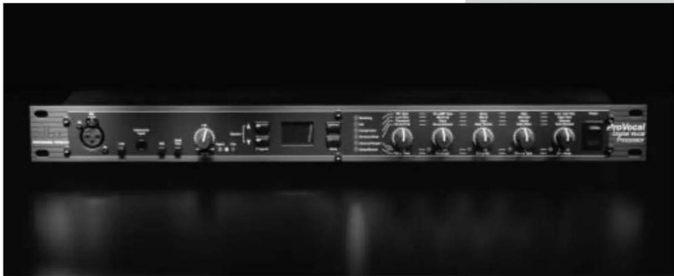
Display W indow
This seven-segment window is used to show all program operating and editing information of the ProVocal™. Note: If digital clipping occurs, the display window will flash: _L .
Effect Select Button and LEDs
This button is used to select any one of the six effect module blocks available in the ProVocal™. Successive presses will scroll through the effect menu. The corresponding LED will light when the effect module is selected and will be lighted in performance mode, when the effect module is on, or used in the current program.
Store Button
This button is used to store any program changes that have been made.
Parameter Edit knobs
These five edit knobs are used to edit the corresponding parameter of the currently selected effect module.
Parameter Edit LEDs
These five LEDs (located beneath the Edit knob) will light when the value of the currently selected parameter value has been changed from the currently stored value.
Power Switch
Turns the ProVocal ^TM on and off.
ProVocal™
Section 2
Operation
DETAILED
PARAMETERS,
BASIC
OPERATION
AND
UTILITY

natural_image
Front panel of a ProVocal Audio Analyzer with multiple knobs and control buttons (no visible text or labels)2.1 Detailed Parameters
This Section has been created to offer an overview and explanation of the effects available in the ProVocal™, as well as a basic tutorial guide for operation of the unit.
Modeling - Mic Type - 0F, and d 1-d9 and C 1-C9
This parameter offers the selection of several different microphone models including:
Setting Microphone LED Display Description
- None (Flat) OF Off
Models w/Dynamic Mic as input
- Oktava d / Small Diaphragm Condenser (Pencil) Mic
| 3. | Audio TechnicaTM AT4033 | d2 | Large Diaphragm Condenser Mic |
| 4. | ShureTM KSM32 | d3 | Large Diaphragm Condenser Mic |
| 5. | AKGTM 414 | d4 | AKG 414 – Large Diaphragm Condenser Mic |
| 6. | AKGTM C12 | d5 | AKG C12 – Tube Condenser Mic |
| 7. | RCA Ribbon d6 | Ribbon Mic | |
| 8. | ShureTM Green Bullet | d7 | Harmonica Mic |
| 9. | Telephone | d8 | Telephone |
| 10. | Megaphone | d9 | Megaphone |
Models w/Condenser Mic as input
| 11. | Oktava | [1] | Small Diaphragm Condenser (Pencil) Mic |
| 12. | Audio TechnicaTM AT4033 | [2] | Large Diaphragm Condenser Mic (measured) |
| 13. | ShureTM KSM32 | [3] | Large Diaphragm Condenser Mic |
| 14. | AKGTM 414 | [4] | AKG 414 – Large Diaphragm Condenser Mic |
| 15. | AKGTMC12 | [5] | AKG C12 – Tube Condenser Mic |
| 16. | RCATM Ribbon | [6] | Ribbon Mic |
| 17. | ShureTM Green Bullet | [7] | Harmonica Mic |
| 18. | Telephone | [8] | Telephone |
| 19. | Megaphone | [9] | Megaphone |
Shure, AKG, Audio Technica and RCA are Registered trademarks of their respective companies. The aforementioned names and models are used solely to indicate microphones used for analyzation in the development of this product. It is not implied in any way that there is any association with or endorsement by any of the named manufacturers.
Modeling - Pre-AMP Type - OF and E1-E9
This parameter offers the selection of several different pre-amp types including:
| OF | - None |
| t0 | - Tube Pre-Amp1 |
| t1 | - Tube Pre-Amp2 |
| t2 | - Tube Pre-Amp3 |
| t3 | - Tube Pre-Amp4 |
| t4 | - Tube Pre-Amp5 |
| t5 | - Tube Pre-Amp6 |
| t6 | - Tube Pre-Amp7 |
| t7 | - Tube Pre-Amp8 |
| t8 | - Tube Pre-Amp9 |
| t9 | - Tube Pre-Amp1 |
Modeling - Drive - 0 to 99
This parameter controls the input drive of the signal flowing into the microphone preamp model. Values are from 0-99.
Modeling - Gain - 0 to 99
This parameter controls the input gain of the signal flowing into the microphone preamp model. Values are from 0-99.
Modeling - Low-Cut Freq - 0 to 50
This parameter controls the low-cut frequency. All audio below this frequency will be removed. Values are from 0-50.
EQ - Low Gain --12 to 12 (+/-12dB @ 80Hz)
This parameter controls the Low-gain output of the EQ section and ranges from -12 to +12dBu.
EQ - Mid Frequency - 0 to 61 (400Hz to 8kHz)
EQ - Mid Q - 0 to 10 (.25-16)
This parameter is used to select the mid Q curve of the EQ. Selections are from 0 to 10, giving Qs of: .25, .5, .75, 1.0, 1.25, 2.0, 4.0, 8.0 and 16.0.
EQ - Mid Gain - -12 to 12
This parameter controls the Mid-gain output of the EQ section and ranges from -12 to +12dBu.
EQ - High Gain - -12 to 12 (+/-12dB @ 12kHz)
This parameter controls the High-gain output of the EQ section and ranges from -12 to +12dBu.
Compressor - Threshold - 1 to 60
Adjust this knob to set the threshold of compression from -40dBu (7.8mVrms) to +20dBu. Setting the Compressor THRESHOLD at its highest level will prevent all but the highest level peaks from being compressed. Setting the Compressor RATIO to 1:1 will turn the Compressor off, regardless of the setting of the Compressor THRESHOLD control.
Compressor - Ratio - 0 to 50 (1:1 - Inf:1)
Rotate this control clockwise to increase the amount of compression from 1:1 (no compression) up to :1 (no increase in output level, regardless of input level increases above threshold.)
Compressor - Gain - 0 to 20 (0-20dB)
This control is used to adjust the output gain of the Compressor module in 1dB increments.
Compressor - Attack - 1 to 99 (1-200ms)
The ATTACK control sets the amount of time it takes the ProVoca ^™ to begin compressing a signal (once the detector has sensed a signal above threshold). The ATTACK range is from 1 (FAST) for a tighter and more noticeable compression effect with very little overshoot) to 99 (SLOW)
(for more delayed, gradual compression). A very fast ATTACK setting will cause the ProVocal™ to act like a peak limiter even though RMS detection circuitry is used. Slower ATTACK settings cause the ProVocal™ to act like an RMS or averaging detecting compressor/limiter.
Compressor - Release - 1 to 99 (360-5dB/sec)
The RELEASE control sets how fast the compression circuit returns the input to its original level. The RELEASE rate is from FAST (where compression follows the envelope of the program material very tightly) to SLOW (for very smooth compression). There is no absolute right way to set the ATTACK and RELEASE controls. However, in general, you will want them set slow enough to avoid pumping or breathing sounds caused when background sounds are audibly modulated by the dominant signal energy, yet the release must be fast enough to avoid suppression of the desired signal after a sudden transient or loud note has decayed.
Note: ATTACK and RELEASE controls operate together and in conjunction with the RATIO control. Changing one control may necessitate changing another setting.
De-Esser/Gate - De-Ess Frequency - 1 to 99 (800Hz-8kHz)
This parameter is used to set the frequency that the De-Esser module will process.
De-Esser/Gate - De-Ess Amount - 1 to 99
This parameter is used to set the overall sensitivity amount of the De-Esser module.
De-Esser/Gate - Gate Threshold - 1 to 60 (-55dBu - +5dBu)
Adjusting the this control sets the level at which the gate will open and allow the signal at the input to pass through to the output. Turning the knob fully counter clockwise (to off) allows the gate to pass all signals unattenuated, effectively bypassing the gate. Turning the knob fully clockwise causes the gate to attenuate input signals below +10dBu. The amount of attenuation depends on the setting of the depth control.
De-Esser/Gate - Gate Ratio - 0 to 99
This parameter is used to control the amount that all signal below the threshold will be reduced.
De-Esser/Gate - Gate Release - 1 to 99 (360-5dB/sec)
Adjusting the RELEASE control sets how fast the gate opens once the input signal rises above the threshold. The release rate is from .01 seconds (fully counter clockwise) to 3 seconds (fully clockwise).
Chorus/Flanger - Type - CH or FL
This parameter is used to select either the Chorus or Flanger effect.
Chorus/Flanger - Speed - 0-99
This parameter is used to set the speed of the Chorus or Flanger effect.
Chorus/Flanger - Depth - 0-99
This parameter is used to set the depth of the Chorus or Flanger effect.
Chorus/Flanger - Mix - 1-94
This parameter is used to set the amount of Chorus/Flanger effect that is mixed with the dry signal.
Chorus/Flanger - CC - 1-10
This parameter is used to select the desired parameter to control with MIDI Settings are as follows: 1: Modeling Microphone, 2: Microphone Preamp Gain, 3: Compressor Gain, 4: Chorus/Flanger Speed, 5: Chorus/Flanger Depth, 6: Chorus/Flanger Mix, 7: Delay Time, 8: Delay Feedback, 9: Delay Input Level and 10: Reverb Mix/Decay.
Delay/Reverb - Delay time - 0-91 (0-1380ms)
This parameter is used to set the delay time of the Delay effect. Delay times range from 0-1380ms, and are measured in 15ms increments.
Delay/Reverb - Delay Feedback - 0-95
This parameter is used to set the amount feedback in the Delay effect. The delay feedback is measured in percentages (0-95%) and changes are made in 1% increments.
Delay/Reverb - Delay Mix - 0-99, 1
This parameter is used to set the amount of Delay effect that is mixed with the dry signal. When set to all wet, no dry signal will be heard. In a typical multi-track recording situation, the main vocal signal is recorded dry on to one track. This track will then be re-recorded on to a second track will the delay set to all wet. During mix-down, the engineer can control the blend of both tracks in real time.
Delay/Reverb - Reverb Type - Off, St, rO, CL, PL, HA, AP, CH, gA, Ar and SP
This parameter is used to select the reverb type module. Types include:
| SE=Studio | PL=Plate | CH=Church | SP=Spring |
| ro=Wood Room | HA=Hall | 9A=Parking Garage | |
| CL=Club | AP=Amphitheater | Rr=Arena |
Delay/Reverb - Mix/Decay - 0-99, 1
The Mix (1) parameter is used to set the amount of Reverb effect that is mixed into the dry signal. The Decay (2) parameter is used to select the length of the reverb decay.
2.2 Basic Operation
The following information is provided to get you up and running with basic editing information that will help you get the most out of your ProVocal™.
Making Connections
- Turn off all equipment before making any connections.
- Install the ProVocal™ in your rack with the provided rack screws. It is essential that when the ProVocal™ is being mounted in a rack mounting enclosure, the unit should be positioned with enough room (at least 1U of space above the unit and 1U of space below the unit) to allow proper ventilation. The ProVocal™ should not be mounted above or below anything that generates excessive heat. Ambient temperatures should not exceed 113^ (45^) when equipment is in use. Although the unit is shielded against radio frequency and electromagnetic interference, extremely high fields of RF and EMI should be avoided where possible.
- Make audio connections via XLR, 1/4" TRS, or 1/4" TS plugs (S/PDIF for digital output). With the flexibility of the ProVocal™, various connection options are available. For input connection, use the XLR Microphone, 1/4" line or 1/4" instrument (front panel) inputs. For analog
output connections, use either XLR or 1/4" Line output.
- Apply power to the ProVocal™. Connect the AC power cord to the AC power receptacle on the back of the unit. Route the AC power cord to a convenient power outlet away from audio lines. The unit may be turned on and off from the front panel power switch or from a master equipment power switch.
- After all connections have been made, make the appropriate front panel line settings i.e.: Line switch, 48Volt switch (and/or 20dB Pad), and adjust the Gain adjustment until the signal LED lights, with the clip LED only lighting occasionally.
Program Operation/Edit Mode
After all connections have been made, you are ready to use the ProVocal™. The following information will provide you with basic guidelines to get the most out of your unit.
- Program Scrolling - To scroll through any one of the 40 Factory and 40 User programs, use the
up and down buttons. User Program are numbered 1-40, and Factory Programs are numbered 41-80. - Program Editing - Once a program has been selected, you can fine-tune the program to your requirements, and then save it as a User program by using the following procedure.
- To access a selected effect module block, simply press the
- Once the effect module to edit has been reached, use any of the five parameter knobs to edit the parameter of the corresponding effect indicated in the effect matrix. The display window will show the parameter value in real time.

natural_image
Front panel of a black electronic device with five rotary knobs and a display (no visible text or labels)Note that the parameter knob LED will light once the parameter's stored value has been reached.
- Once all of your changes have been made to the current program, you can now save this custom program into the User bank of Programs. To save your changes, press the
- Effect Bypass - To bypass all effect in the ProVocal, press the
2.3 Utility functions and Factory Reset
Utility Functions
The ProVocal™ provides a Utility section which will give the user access to operation functions including: Sample-Rate Selection, MIDI CC Selection and MIDI Channel Selection. The following information tells you how to access and edit these features. This section also includes the procedure for resetting the unit to its original factory settings.
- Change CC Number- Turn the power button on, while holding
button. The display will read: Use Now press the button and use Mic Type knob to change the CC number. Once your selection has been made, press the button to exit the Utility menu. - MIDI Channel Selection- Turn the power button on, while holding
button. The display will read: UE Now press the button and the display will read: CH. use Mic Type knob to change the MIDI channel. Selections are from 1-16 and o (omni). Once your selection has been made, press the button to exit the Utility menu. - Sample Rate Select- Turn the power button on, while holding
button. The display will read: UE Now press the button to toggle between 44.1kHz and 48kHz sample rates. Once your selection has been made, press and hold the button to exit the Utility menu.
Factory Reset
In the event that a factory reset is required, please use the following procedure:
- Press and hold the
2.4 Factory Program List
- Dry Studio Vocal Mic and Pre-amp Modeling
- Live in a Hall Mic and Pre-amp Modeling, Hall Reverb
- Special Effect Telephone Mic and Pre-amp Modeling, modulation effects
- Wood Room Mic and Pre-amp Modeling, Wood Room Reverb
- Club Land Mic and Pre-amp Modeling, Club Reverb
- Compressed and
De-essed Studio Voc Mic and Pre-amp Modeling with light compression and de-essing - Newsreel recording Vintage mic model
- 40's Vocal Vintage ribbon mic model with plate reverb
- Tube Mic Mic and Pre-amp modeling
- Stage Rock Modulation, delay and reverb
- Male Studio 1 Dynamic modeled as a condenser, pre-amp modeling
- Male Studio 2 Dynamic modeled as a tube condenser mic, pre-amp modeling
- Male Studio 3 Dynamic modeled as a ribbon, pre-amp modeling
- Male Studio 4 Condenser modeled as a tube condenser mic, pre-amp modeling
- Male Studio 5 Condenser modeled as a ribbon mic, pre-amp modeling
- Male Live 1 Dynamic modeled as a condenser, Chorus, Delay, Reverb
- Male Live 2 Dynamic modeled as a condenser, Chorus, Delay, Reverb
- Male Live 3 Dynamic modeled as a condenser, Chorus, Delay, Reverb
- Male Live 4 Dynamic modeled as a condenser, Chorus, Delay, Reverb
- Male Live 5 Dynamic modeled as a condenser, Chorus, Delay, Reverb
- Female Studio 1 Dynamic modeled as a condenser, pre-amp modeling
- Female Studio 2 Dynamic modeled as a tube condenser micr, pre-amp modeling
- Female Studio 3 Dynamic modeled as a ribbon, pre-amp modeling
- Female Studio 4 Condenser modeled as a tube condenser micr, pre-amp modeling
- Female Studio 5 Condenser modeled as a ribbon micr, pre-amp modeling
- Female Live 1 Dynamic modeled as a condenser, Chorus, Delay, Reverb
- Female Live 2 Dynamic modeled as a condenser, Chorus, Delay, Reverb
- Female Live 3 Dynamic modeled as a condenser, Chorus, Delay, Reverb
- Female Live 4 Dynamic modeled as a condenser, Chorus, Delay, Reverb
- Female Live 5 Dynamic modeled as a condenser, Chorus, Delay, Reverb
- Telephone Dynamic as vintage telephone mic
- Megaphone Dynamic as a small megaphone
- Harmonica Overdrive Dynamic as a harmonica mic into a tube pre-amp
- Alien Vocal Special effects
- Grunge Vocal Tube pre-amp effects
- Radio Announcer Vintage radio announcer sound
- Arena Announcer PA horn effect into a large arena
- Spooky Special effects
- Tube Screaming High tube saturation
- Concrete Cavern Washy reverb with delay
ProVocal™
Section 3
DIGITAL APPLICATIONS
APPLICATION GUIDE
natural_image
Front panel of a ProVocal Digital Vocal Processor with multiple knobs and control buttons (no visible text or labels)3.1 Basic Analog Connection of the ProVocal
- Turn off all equipment before making any connections.
- Install the ProVocal in your rack with the provided rack screws. It is essential that when the ProVocal is being mounted in a rack mounting enclosure, the unit should be positioned with enough room (at least 1U of space above the unit and 1U of space below the unit) to allow proper ventilation. The ProVocal should not be mounted above or below anything that generates excessive heat. Ambient temperatures should not exceed 113^ ( 45^ ) when equipment is in use. Although the unit is shielded against radio frequency and electromagnetic interference, extremely high fields of RF and EMI should be avoided where possible.
- Make audio connections via XLR, 1/4" TRS, or 1/4" TS plugs. With the flexibility of the ProVocal, various connection options are available. For input connection, use the XLR Microphone, 1/4" line or 1/4" instrument (front panel) inputs. For analog output connections, use either XLR or 1/4" Line output. The use of more than one connector at a time for the output section could unbalance balanced lines, cause phase cancellations, short a conductor to ground, or cause damage to other equipment connected to the ProVocal.
- Apply power to the ProVocal. Connect the AC power cord to the AC power receptacle on the back of the unit. Route the AC power cord to a convenient power outlet away from audio lines. The unit may be turned on and off from the front panel power switch or from a master equipment power switch.
3.2 Connection to a Mixing Console
1). Connect your mic cable to the Mic input of the ProVocal™.
NOTE: If you are using a mic with a separate power supply, such as a tube microphone, make sure that you are not sending two sources of +48V phantom power to the mic. Use the +48V from the mic's power supply. Use the +48V Phantom Power switch on the ProVocal for all other microphones which require phantom power.
2). Set the front panel of the ProVocal to the desired settings, including Phantom Power, 20dB pad, etc. Connect the line output of the ProVocal to the console's LINE INPUT, and ensure that the console's input selection switch is set to LINE, and the console's gain control is set appropriately low.
3). Turn the ProVocal's GAIN control to the minimum position and apply power to the ProVocal. Make sure your console's gain fader is at the nominal level and begin to slowly increase the gain of the ProVocal using the GAIN control. You should increase the gain until the mixing/recording device is operating at nominal signal input level.

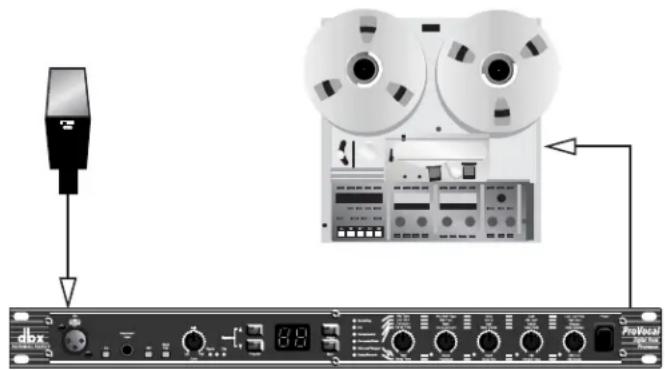
3.3 Direct Connection to a Recorder
1). Make microphone connections, being careful to keep the GAIN control in the minimum (+30dB) position.
2). Connect the ProVocal's Line outputs directly to the audio inputs of your recorder.
3). Enable the record function of the specific track of the recorder and open the specific tape track return in the console which corresponds to the track to which the ProVocal is connected. As you increase the setting of the GAIN control, you should begin to hear the input of the ProVocal running through the recorder and returning to your console as a tape return.
3.4 Direct Connection to a DAW (CPU)
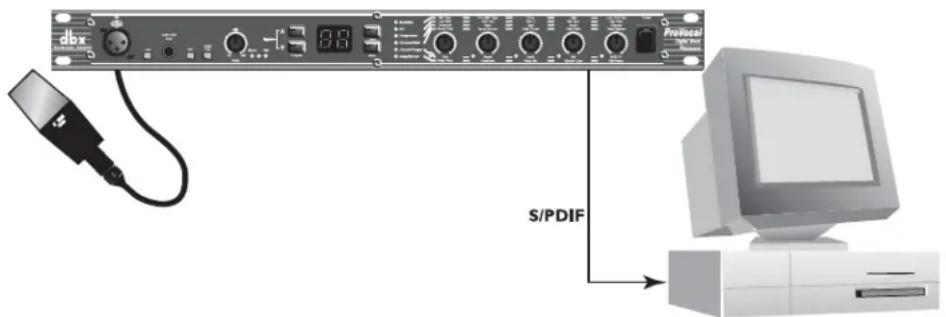
Connections
- Connect the source to the desired 1/4" TRS or XLR input.
- Connect the S/PDIF output of the ProVocal and run into the S/PDIF input interface of the DAW (CPU).
3.5 A/D Conversion

Connections
- Connect the source to the desired 1/4" TRS or XLR input.
- Connect the S/PDIF output of the ProVocal and run into the S/PDIF input interface of the DAW (CPU).
3.6 Analog and Digital Output Application

This application allows you to send a digital signal to a receiving device (such as a DAW or digital recorder) and route the analog signal to a monitoring device (such as a mixer or headphone amplifier) simultaneously.
Connections
- Connect the source to the desired 1/4" TRS or XLR input.
- Connect the S/PDIF output of the ProVocal and run into the S/PDIF input interface of the DAW (CPU).
- Connect the 1/4" TRS or XLR output of the ProVocal and run into the 1/4" TRS or XLR input of the monitoring device.
ProVocal™
Appendix
APPENDIX
APPENDIX
Block Diagram dbx Type IV™ White Paper Specifications

natural_image
Front view of a ProVocal audio recording device with multiple knobs and control buttons (no visible text or labels)Block Diagram
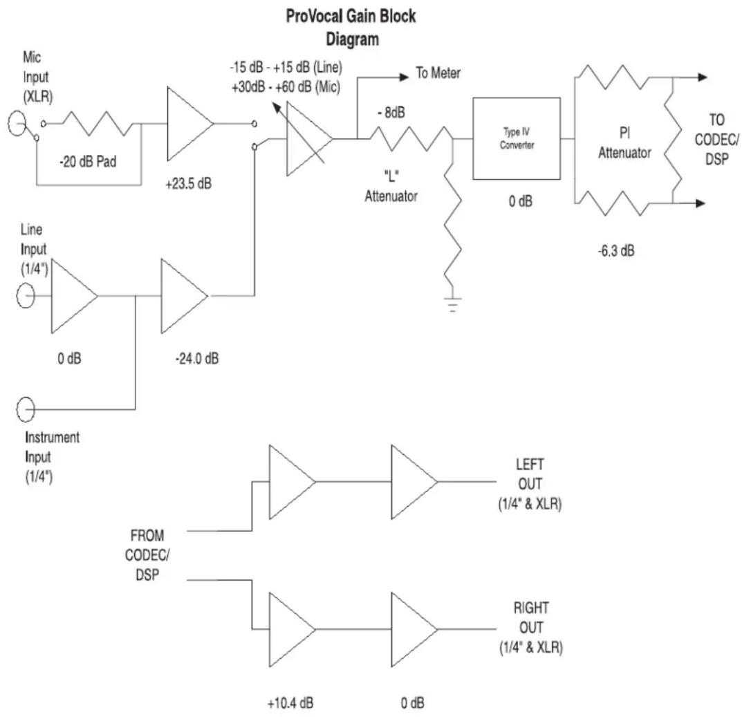
flowchart
graph TD
    A["Input (XLR)"] --> B["-20 dB Pad"]
    B --> C["Line Input (1/4")"]
    C --> D["0 dB"]
    D --> E["Instrument Input (1/4)"]
    F["Line Input (1/4")"] --> G["-24.0 dB"]
    G --> H["Inverter"]
    H --> I["To Meter"]
    I --> J[""L" Attenuator"]
    J --> K["Type IV Converter"]
    K --> L["Attenuator"]
    L --> M["PI Attenuator"]
    M --> N["TO CODEC/DSP"]
    O["Instrument Input (1/4)"] --> P["FROM CODEC/DSP"]
    P --> Q["LEFT OUT (1/4" & XLR)"]
    R["Inverter"] --> S["RIGHT OUT (1/4" & XLR)"]
    T["Output"] --> U["+10.4 dB"]
    V["Output"] --> W["0 dB"]
Type IV™ White Paper
dbx Type IV™ Conversion System White Paper by Roger Johnson
The dbx Type IV ^TM Conversion System is a proprietary analog-to-digital (A/D) conversion process that combines the best attributes of digital conversion and analog recording processes to preserve the essence of the analog signal when it is converted to a digital format. dbx Type IV ^TM not only exploits the wide linear dynamic range of today's A/D converters, but also enhances it and extends the useable dynamic range beyond the linear range. By providing a logarithmic “Type IV ^TM Over Region” above the linear A/D range, we benefit from the extended high-level headroom that is inherent in analog recording without compromising the noise performance of the A/D conversion process.
Digital conversion and recording processes proliferated in the 1980's primarily due to the "cleaner" sound of digital versus analog, an advantage resulting from the comparatively wider linear dynamic range of digital. Anyone who is familiar with the technical specifications of digital equipment knows that the typical maximum signal-to-noise specifications for 16-bit systems is in the neighborhood of 90-something dB. Compare this to the typical signal-to-noise specifications for professional analog tape of about 55dB without the aid of noise reduction and around 75 to 85dB with noise reduction such as dbx Type I™ or Type II™ applied.
This seemingly tremendous signal-to-noise advantage of digital over analog would suggest that digital would become the unanimous choice for recording. For the most part this has occurred, not totally due to its signal-to-noise advantage, but as much due to the benefits of digital storage such as random access and the inherent ability to withstand degradation, unlike that of analog tape or LP's. In spite of the benefits of digital, no one in the audio world can refute the rediscovery of analog recording and tube gear that has occurred in the 90's, attributable to the quest for that "analog character" that is missing from digital recordings. This continued use of analog gear with modern digital systems brings to light a favorable characteristic of analog recording which those who abandoned analog and jumped on the digital bandwagon were either never aware of or simply took for granted.
Anyone who has ever used analog tape knows that you can “hit it hard” without destroying the recording. The printed specifications of analog tape don’t take into account the practical headroom available. The max signal-to-noise specification of analog tape is measured by defining the “max” signal as the point where a given signal level and frequency produces a given percent Total Harmonic Distortion (THD)—typically the level at which a 1 kHz signal produces 3% THD. In actual use, the signal can easily exceed this “max” signal level by 5, 10, or even 15dB on peaks, depending on the type of signal being recorded, without unacceptable artifacts. High signal levels can be tolerated (i.e. more headroom) at the expense of increased THD which, incidentally, is often desirable as an effect, evidenced by the renewed popularity of tube equipment.
The obvious conclusion is that analog recording actually has more useable dynamic range than the specifications seem to indicate. For example, let's say we're recording a kick drum. If analog tape measures 55dB from the 3% THD point down to the RMS noise floor and the peaks of the kick drum exceed the 3% THD level by, say, 15dB and it still sounds good, then we have 15dB of extra useable headroom. Therefore, we end up with 70dB of useable dynamic range. Throw in noise reduction and we push into the 90-something dB dynamic range territory of 16-bit digital. This explains why well-recorded analog master tapes make good-sounding CD's with no objectionable noise.
One main drawback of digital is that it inherently lacks this forgiving and beneficial characteristic of analog recording. Although digital conversion exhibits wide linear dynamic range, when you run out of headroom for high-level signals, hard clipping or even ugly signal wrap-around occurs, not to mention that A/D converters have their own nasty side effects such as going unstable when their modulator is overdriven with high-level signals.
This shortcoming of digital conversion has drastically affected the way users operate their equipment. Users are
paranoid of overdriving the converter input and end up recording at lower levels to ensure that there is ample headroom to allow for the large peaks that would ruin an otherwise perfect recording. This, of course, compromises signal-to-noise performance since the signal is now closer to the noise floor. Because users of digital equipment have to be extremely careful not to exceed 0dB FS (full-scale), they must use peak-reading headroom meters. On the other hand, the forgiving nature of analog tape allows users of analog recording equipment the luxury of only needing to monitor the average level using VU meters, often having no peak indicators whatsoever. If only digital were more forgiving like analog, we could really exploit its wide dynamic range and more completely capture the essence of the musical performance.
Enter the dbx Type IV ^TM Conversion System. Like its related predecessor technologies—Type I ^TM , Type II ^TM , and Type III ^TM —dbx Type IV ^TM succeeds in preserving the wide dynamic range of the original analog signal within a limited dynamic range medium. Whereas Type I ^TM and Type II ^TM expand the dynamic range of analog tape and other limited dynamic range media, and the simultaneous encode/decode process of Type III ^TM similarly expands the limited dynamic range through minimum-delay devices, Type IV ^TM breaks new ground by greatly enhancing the useable dynamic range of the analog-to-digital conversion process.
The dbx Type IV ^TM Conversion System combines proprietary analog and digital processing techniques to capture a much wider dynamic range than the A/D converter could by itself, preserving the maximum amount of information from the analog signal. This information is then encoded within the available bits of whichever A/D converter is used. This means that Type IV ^TM improves the performance of any A/D converter, from low-cost 16-bit to high-performance 24-bit! And no decoding is necessary beyond the conversion process!
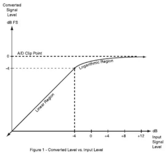
As we have previously mentioned, digital systems have a wide linear region compared to analog tape and the dynamic range of A/D converters has improved significantly in recent years. The dbx Type IV ^TM Conversion System takes advantage of this and utilizes the top 4dB of the A/D converter's linear dynamic range to create a logarithmic “overload region.” This allows high-level transient signals passing far above the point where the overload region begins to be adequately represented in just 4dB of the converter's dynamic range, whereas a typical A/D converter would clip. With Type IV ^TM , you can never clip the A/D converter!
line
| Input Signal Level (dB) | Converted Signal Level (dB FS) | | ----------------------- | ------------------------------ | | -4 | -4 | | 0 | 0 | | +8 | 0 | | +12 | 0 |Fig. 1 illustrates this concept showing the level of the converted signal below and above the start of the overload region. The converted signal level is plotted along the Y-axis (vertical axis) of the plot vs. the level of the input signal along the X-axis (horizontal axis). The logarithmic mapping of the overload region begins 4 dB below 0 dB FS (full-scale) of the A/D converter. What this shows is that below -4 dB FS, in the linear region, the output signal is the same as the input signal. Above this, in the logarithmic region, high-level input signals get “mapped” into the top 4 dB of the A/D converter. This mapping is analogous to the signal compression effect that occurs when recording high-level signals onto analog tape.

line
| Input Signal Level | Value | | ------------------ | ----- | | +12 | 0 dB FS | | +8 | 0 dB FS | | +4 | 0 dB FS | | 0 | 0 dB FS | | -4 | 0 dB FS | | -4 | -4 dB | The diagram illustrates a hierarchical conversion of signal levels into a network structure based on the input signal level. Below it, a vertical arrow indicates the A/D Converter Linear Region. The label 'TYPE IV™ Over Region' points to the output region.Figure 2 - Input Signal Levels Mapped to Type IV Over Region
Fig. 2 illustrates the mapping function in a different way. Input levels are shown on the left of the graph, while converted levels are shown on the right. Notice the mapping of large signal excursions to the 4dB "Type IV™ Over Region."
One might question the validity of such an approach—trying to represent a lot of signal information within a smaller “space.” The reason why this is not only valid but makes a whole lot of sense is that the digital codes in a converter are linear, or evenly-spaced, meaning that each consecutive code represents the same change in voltage of the input signal. This implies that half of the digital codes are used to represent input signals whose voltage level is below 1/2 of the full-scale A/D input voltage, while the other half of the codes are used to represent signals above 1/2 of the full-scale A/D input voltage. This seems reasonable until you realize that 1/2 of the full-scale input is only 6dB below full-scale! So half of the codes are used to represent only the top 6 dB of signal information, while the other half are used to represent the remaining 80 to 110dB of signal information, depending on the quality of the converter. It seems not only reasonable, but also desirable, to utilize the increased signal resolution afforded by this density of digital codes to represent more input dynamic range in this region.
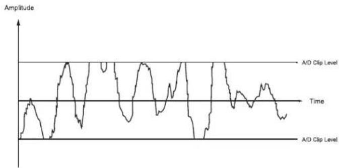
Another advantage of the logarithmic mapping of our dbx Type IV ^TM Conversion System is that it preserves the high-frequency detail of the signal in the overload region. Figs. 3a through 3d illustrate what happens when you overload an A/D converter without Type IV ^TM . Fig. 3a shows an input signal having both low-frequency and high-frequency components. When the signal overloads, or clips, (Fig. 3b) at the A/D converter, a disproportionate amount of high-frequency signal information is lost compared with the low-frequency information. The low and high-frequency components of the signal are separated in Fig. 3c to illustrate this more clearly. As you can see, the low frequency signal simply gets distorted but maintains most of its signal characteristics, while sections of the high-frequency signal are completely lost! With dbx Type IV ^TM , its mapping preserves high-frequency signal information, as illustrated in Fig. 3d, since the signal is confined within the Type IV ^TM Over Region and never clips. The dashed line indicates the original input signal level. Below the Over Region no mapping occurs, while above this, mapping keeps all peaks of the signal below the A/D clip level, thus preserving the high-frequency content of the signal.

line
| Time | Amplitude | |------|---------| | 0 | -1 | | 1 | 0 | | 2 | 1 | | 3 | -1 | | 4 | 0 | | 5 | 1 | | 6 | -1 | | 7 | 0 | | 8 | 1 | | 9 | -1 | | 10 | 0 | | 11 | 1 | | 12 | -1 | | 13 | 0 | | 14 | 1 | | 15 | -1 | | 16 | 0 | | 17 | 1 | | 18 | -1 | | 19 | 0 | | 20 | 1 | | 21 | -1 | | 22 | 0 | | 23 | 1 | | 24 | -1 | | 25 | 0 | | 26 | 1 | | 27 | -1 | | 28 | 0 | | 29 | 1 | | 30 | -1 | | 31 | 0 | | 32 | 1 | | 33 | -1 | | 34 | 0 | | 35 | 1 | | 36 | -1 | | 37 | 0 | | 38 | 1 | | 39 | -1 | | 40 | 0 | | 41 | 1 | | 42 | -1 | | 43 | 0 | | 44 | 1 | | 45 | -1 | | 46 | 0 | | 47 | 1 | | 48 | -1 | | 49 | 0 | | 50 | 1 | | 51 | -1 | | 52 | 0 | | 53 | 1 | | 54 | -1 | | 55 | 0 | | 56 | 1 | | 57 | -1 | | 58 | 0 | | 59 | 1 | | 60 | -1 | | 61 | 0 | | 62 | 1 | | 63 | -1 | | 64 | 0 | | 65 | 1 | | 66 | -1 | | 67 | 0 | | 68 | 1 | | 69 | -1 | | 70 | 0 | | 71 | 1 | | 72 | -1 | | 73 | 0 | | 74 | 1 | | 75 | -1 | | 76 | 0 | | 77 | 1 | | 78 | -1 | | 79 | 0 | | 80 | 1 | | 81 | -1 | | 82 | 0 | | 83 | 1 | | 84 | -1 | | 85 | 0 | | 86 | 1 | | 87 | -1 | | 88 | 0 | | 89 | 1 | | 90 | -1 | | 91 | 0 | | 92 | 1 | | 93 | -1 | | 94 | 0 | | 95 | 1 | | 96 | -1 | | 97 | 0 | | 98 | 1 | | 99 | -1 | | 100 | 0 |Figure 3a - Signal Having Low and High Frequency Content
line
| Time | Amplitude | |------|-----------| | 0 | 0 | | 1 | 1 | | 2 | -1 | | 3 | 2 | | 4 | -2 | | 5 | 3 | | 6 | -3 | | 7 | 4 | | 8 | -4 | | 9 | 5 | | 10 | -5 | | 11 | 6 | | 12 | -6 | | 13 | 7 | | 14 | -7 | | 15 | 8 | | 16 | -8 | | 17 | 9 | | 18 | -9 | | 19 | 10 | | 20 | -10 | | 21 | 11 | | 22 | -11 | | 23 | 12 | | 24 | -12 | | 25 | 13 | | 26 | -13 | | 27 | 14 | | 28 | -14 | | 29 | 15 | | 30 | -15 | | 31 | 16 | | 32 | -16 | | 33 | 17 | | 34 | -17 | | 35 | 18 | | 36 | -18 | | 37 | 19 | | 38 | -19 | | 39 | 20 | | 40 | -20 | | 41 | 21 | | 42 | -21 | | 43 | 22 | | 44 | -22 | | 45 | 23 | | 46 | -23 | | 47 | 24 | | 48 | -24 | | 49 | 25 | | 50 | -25 | | 51 | 26 | | 52 | -26 | | 53 | 27 | | 54 | -27 | | 55 | 28 | | 56 | -28 | | 57 | 29 | | 58 | -29 | | 59 | 30 | | 60 | -30 | | 61 | 31 | | 62 | -31 | | 63 | 32 | | 64 | -32 | | 65 | 33 | | 66 | -33 | | 67 | 34 | | 68 | -34 | | 69 | 35 | | 70 | -35 | | 71 | 36 | | 72 | -36 | | 73 | 37 | | 74 | -37 | | 75 | 38 | | 76 | -38 | | 77 | 39 | | 78 | -39 | | 79 | 40 | | 80 | -40 | | 81 | 41 | | 82 | -41 | | 83 | 42 | | 84 | -42 | | 85 | 43 | | 86 | -43 | | 87 | 44 | | 88 | -44 | | 89 | 45 | | 90 | -45 | | 91 | 46 | | 92 | -46 | | 93 | 47 | | 94 | -47 | | 95 | 48 | | 96 | -48 | | 97 | 49 | | 98 | -49 | | 99 | 50 | | 100 | -50 |Figure 3b - Signal of Fig. 3a Going Beyond the A/D Clip Level

line
| Time | Amplitude Label | |------|-----------------| | 0 | High-Frequency Information Completely Lost | | 1 | High-Frequency Content | | 2 | High-Frequency Information Completely Lost | | 3 | High-Frequency Content | | 4 | High-Frequency Information Completely Lost | | 5 | High-Frequency Content | | 6 | High-Frequency Information Completely Lost | | 7 | High-Frequency Content | | 8 | High-Frequency Information Completely Lost | | 9 | High-Frequency Content | | 10 | High-Frequency Information Completely Lost | | 11 | High-Frequency Content | | 12 | High-Frequency Information Completely Lost | | 13 | High-Frequency Content | | 14 | High-Frequency Information Completely Lost | | 15 | High-Frequency Content | | 16 | High-Frequency Information Completely Lost | | 17 | High-Frequency Content | | 18 | High-Frequency Information Completely Lost | | 19 | High-Frequency Content | | 20 | High-Frequency Information Completely Lost | | 21 | High-Frequency Content | | 22 | High-Frequency Information Completely Lost | | 23 | High-Frequency Content | | 24 | High-Frequency Information Completely Lost | | 25 | High-Frequency Content | | 26 | High-Frequency Information Completely Lost | | 27 | High-Frequency Content | | 28 | High-Frequency Information Completely Lost | | 29 | High-Frequency Content | | 30 | High-Frequency Information Completely Lost | | 31 | High-Frequency Content | | 32 | High-Frequency Information Completely Lost | | 33 | High-Frequency Content | | 34 | High-Frequency Information Completely Lost | | 35 | High-Frequency Content | | 36 | High-Frequency Information Completely Lost | | 37 | High-Frequency Content | | 38 | High-Frequency Information Completely Lost | | 39 | High-Frequency Content | | 40 | High-Frequency Information Completely Lost | | 41 | High-Frequency Content | | 42 | High-Frequency Information Completely Lost | | 43 | High-Frequency Content | | 44 | High-Frequency Information Completely Lost | | 45 | High-Frequency Content | | 46 | High-Frequency Information Completely Lost | | 47 | High-Frequency Content | | 48 | High-Frequency Information Completely Lost | | 49 | High-Frequency Content | | 50 | High-Frequency Information Completely Lost | | 51 | High-Frequency Content | | 52 | High-Frequency Information Completely Lost | | 53 | High-Frequency Content | | 54 | High-Frequency Information Completely Lost | | 55 | High-Frequency Content | | 56 | High-Frequency Information Completely Lost | | 57 | High-Frequency Content | | 58 | High-Frequency Information Completely Lost | | 59 | High-Frequency Content | | 60 | High-Frequency Information Completely Lost | | 61 | High-Frequency Content | | 62 | High-Frequency Information Completely Lost | | 63 | High-Frequency Content | | 64 | High-Frequency Information Completely Lost | | 65 | High-Frequency Content | | 66 | High-Frequency Information Completely Lost | | 67 | High-Frequency Content | | 68 | High-Frequency Information Completely Lost | | 69 | High-Frequency Content | | 70 | High-Frequency Information Completely Lost | | 71 | High-Frequency Content | | 72 | High-Frequency Information Completely Lost | | 73 | High-Frequency Content | | 74 | High-Frequency Information Completely Lost | | 75 | High-Frequency Content | | 76 | High-Frequency Information Completely Lost | | 77 | High-Frequency Content | | 78 | High-Frequency Information Completely Lost | | 79 | High-Frequency Content | | 80 | High-Frequency Information Completely Lost | | 81 | High-Frequency Content | | 82 | High-Frequency Information Completely Lost | | 83 | High-Frequency Content | | 84 | High-Frequency Information Completely Lost | | 85 | High-Frequency Content | | 86 | High-Frequency Information Completely Lost | | 87 | High-Frequency Content | | 88 | High-Frequency Information Completely Lost | | 89 | High-Frequency Content | | 90 | High-Frequency Information Completely Lost | | 91 | High-Frequency Content | | 92 | High-Frequency Information Completely Lost | | 93 | High-Frequency Content | | 94 | High-Frequency Information Completely Lost | | 95 | High-Frequency Content | | 96 | High-Frequency Information Completely Lost | | 97 | High-Frequency Content | | 98 | High-Frequency Information Completely Lost | | 99 | High-Frequency Content | | 100 | High-Frequency Information Completely Lost (A/D Clip Level) |Figure 3c - Disproportionate Loss of High-Frequency Information Due to Clipping

line
| Time | Amplitude (dB FS) | |------|-------------------| | 0 | -4 | | 1 | -3 | | 2 | -2 | | 3 | -1 | | 4 | 0 | | 5 | 1 | | 6 | 2 | | 7 | 3 | | 8 | 4 | | 9 | 3 | | 10 | 2 | | 11 | 1 | | 12 | 0 | | 13 | -1 | | 14 | -2 | | 15 | -3 | | 16 | -4 | | 17 | -3 | | 18 | -2 | | 19 | -1 | | 20 | 0 | | 21 | 1 | | 22 | 2 | | 23 | 3 | | 24 | 4 | | 25 | 3 | | 26 | 2 | | 27 | 1 | | 28 | 0 | | 29 | -1 | | 30 | -2 | | 31 | -3 | | 32 | -4 | | 33 | -3 | | 34 | -2 | | 35 | -1 | | 36 | 0 | | 37 | 1 | | 38 | 2 | | 39 | 3 | | 40 | 4 | | 41 | 3 | | 42 | 2 | | 43 | 1 | | 44 | 0 | | 45 | -1 | | 46 | -2 | | 47 | -3 | | 48 | -4 | | 49 | -3 | | 50 | -2 | | 51 | -1 | | 52 | 0 | | 53 | 1 | | 54 | 2 | | 55 | 3 | | 56 | 4 | | 57 | 3 | | 58 | 2 | | 59 | 1 | | 60 | 0 | | 61 | -1 | | 62 | -2 | | 63 | -3 | | 64 | -4 | | 65 | -3 | | 66 | -2 | | 67 | -1 | | 68 | 0 | | 69 | 1 | | 70 | 2 | | 71 | 3 | | 72 | 4 | | 73 | 3 | | 74 | 2 | | 75 | 1 | | 76 | 0 | | 77 | -1 | | 78 | -2 | | 79 | -3 | | 80 | -4 | | 81 | -3 | | 82 | -2 | | 83 | -1 | | 84 | 0 | | 85 | 1 | | 86 | 2 | | 87 | 3 | | 88 | 4 | | 89 | 3 | | 90 | 2 | | 91 | 1 | | 92 | 0 | | 93 | -1 | | 94 | -2 | | 95 | -3 | | 96 | -4 | | 97 | -3 | | 98 | -2 | | 99 | -1 | | 100 | 0 |Figure 3d - Type IV Mapping Preserves High-Frequency Information
Now you're probably wondering, "What's the catch? I can't get something for nothing so what did I give up?" You may be worried that your A/D noise floor got 4dB worse because we borrowed the top 4dB of your converter. This is certainly a valid concern. Fortunately, we have the answer! Without going into the confidential technical details, by using our proprietary analog and digital Type IV™ processing, we reclaim the original A/D noise level! So what you get is free headroom!
The benefits of the dbx Type IV™ Conversion System can easily be heard by switching it in and out while listening to signals with high-level peaks captured in the Type IV™ Over Region. You will notice an obvious audible difference. With Type IV™ bypassed, you can't help notice the harsh, edgy sound of the A/D converter clipping. With Type IV™ enabled, those nasty artifacts disappear revealing a more open and natural sound. With Type IV™ enabled, you will get a more accurate and pure representation of the original wide-dynamic-range signal. You will absolutely agree that we really do give you "something for nothing." We give you peace of mind knowing that you never have to worry about clipping your A/D again! And when you listen to the noise floor of your A/D, you'll realize that we never compromise your noise performance with Type IV™!
The dbx Type IV ^TM Conversion System succeeds in combining the best of the analog and digital worlds to capture the truest essence and fullest dynamic range of audio signals. Who else but dbx would bring you this technology!
Microphone Modeling Technique
All microphones were measured in a semi-anechoic environment using an Audio Precision ^ System Two Cascade Plus. The microphones were measured at several different SPL levels and calibrated to a reference Earthworks ^ M30 measurement microphone. Using proprietary algorithms, dbx engineering built models of the characteristics of all the mics found in the ProVocal ^TM . They then generated models of several popular dynamic microphones and built a model based on the typical response of these types of mics. A composite model can then be built which removes the characteristics of a typical dynamic mic and adds the characteristics of the desired microphone sound. Similarly, many popular condenser microphones were characterized to form a typical dynamic vocal microphone model. Again, a composite microphone model is formed to remove the characteristics of a typical vocal condenser microphone and then add the specific characteristics of the desired mic sound.
All measurements were performed on-axis. As with any miking situation, microphone placement alters the response. Good mic technique is still essential to get the best possible sound. Also, choosing a good quality input microphone will improve your results. Finally, the age, condition, and even manufacturing variances can subtly alter the response of any microphone. Using dbx's proprietary modeling techniques, we have accurately modeled the mics in our collection. This technology is the most accurate way to represent the sound of these mics without actually spending thousands of dollars on your own collection.
Specifications
Microphone Input
Connector: Female XLR pin 2 hot
Type: Electronically balanced/unbalanced RF filtered
Impedance: 330, Ωbalanced
Maximum Input Level: -9dBu or +11 dBu with 20dB pad engaged
CMRR: >40dB, Typically 55dB at 1kHz
Equivalent Input Noise: Typically -120.2 dBu with a 150Ω source load, 20Hz to 20kHz BW Gain +30dB to +60dB
Line Input (Rear Panel)
Connector: TRS 1/4" jack
Type: Electronically balanced/unbalanced
Impedance: 20kΩ unbalanced, 40kΩ balanced
Maximum Input Level: +18dBu balanced or unbalanced
CMRR: >40dB, Typically 55dB
Gain: -15dB to +15dB
Instrument Input (Front Panel)
Connector: TS 1/4" Jack
Type: Unbalanced
Impedance: 470kΩ
Maximum Input Level: +18dBu unbalanced
Analog Outputs
Connector: Male XLR pin 2 hot and TRS 1/4"
Type: Electronically balanced
Impedance: Balanced 120Ω, unbalanced 60Ω
Maximum Output Level: >+18dBu into 100 kΩ
S/PDIF Digital Output
Connector: RCA
Impedance: 75Ω
A-D System Performance
A-D Conversion: 24-bit, dbx Type IV™ Conversion System
Converter Dynamic Range: 105dB typical, A-weighted, 22kHz bandwidth
102dB typical, unweighted, 22kHz bandwidth
Type IV ^TM Dynamic Range:
Up to 117dB with transient material, A-weighted, 22kHz bandwidth
Up to 115dB with transient material, unweighted, 22kHz bandwidth
Typically 109dB with program material, A-weighted, 22kHz bandwidth
Typically 106dB with program material, unweighted, 22kHz bandwidth
THD+Noise:
0.002% typical at +4 dBu, 1 kHz, input gain at 0dB
Frequency Response:
20Hz to 22kHz, +0/-0.5dB
D-A System Performance
D-A Conversion: 24-bit
Dynamic Range:
103dB typical, A-weighted, 20kHz bandwidth
101dB typical, unweighted, 20kHz bandwidth
THD+Noise:
0.002% typical at +4 dBu, 1kHz, output gain at 0dB
Frequency Response:
20Hz to 20kHz, +0/-0.5dB
Interchannel Crosstalk:
<-85dB at 1kHz, output gain at 0dB
Power Supply:
Operating Voltage:
DO: 120 VAC. 60Hz, 100 VAC 50/60Hz - EU: 220-240 VAC 50/60Hz
Power Consumption:
15 watts
Physical:
Dimensions:
1.75"Hx 5.75"Dx19"W
Weight:
7.14 lbs. (3.24 kg)
dbx®
PROFESSIONAL PRODUCTS
A Harman International Company
8760 South Sandy Pkwy.
Sandy, Utah 84070
Phone: (801) 568-7660
Fax: (801) 568-7662
Questions or comments?
E-mail us at: customer@dbxpro.com
or visit our World Wide Web home page at:
www.dbxpro.com

- IMPORTANT SAFETY INSTRUCTIONS
- SAFETY INSTRUCTIONS
- WARNING FOR YOUR PROTECTION PLEASE READ THE FOLLOWING:
- LITHIUM BATTERY WARNING
- CAUTION!
- ADVARSEL!
- U.K. MAINS PLUG WARNING
- DECLARATION OF CONFORMITY
- Introduction
- Section 1 - Getting Started
- Section 2 - Detailed Parameters/
- Basic Operation and Utility
- Functions
- Section 3 Application Guide
- Appendix
- ProVocal™
- INTRO
- Defining the ProVocal
- Service Contact Info
- Warranty
- Installation Recommendations
- Section 1
- Getting Started
- Rear Panel Connections
- IEC Power Cord Receptacle
- S/PDIF Digital Output Connector
- MIDI In
- Analog Input Connectors
- Analog Output Connectors
- Line Input
- Front Panel Controls
- Microphone Input
- Line Select Switch
- +48 Volt Switch
- 20dB Pad Switch
- Gain Control
- Analog Signal LEDs
- Program Up and Down buttons
- Display W indow
- Effect Select Button and LEDs
- Store Button
- Parameter Edit knobs
- Parameter Edit LEDs
- Power Switch
- Section 2
- DETAILED
- BASIC
- Detailed Parameters
- Modeling - Mic Type - 0F, and d 1-d9 and C 1-C9
- Setting Microphone LED Display Description
- Models w/Dynamic Mic as input
- Models w/Condenser Mic as input
- Modeling - Pre-AMP Type - OF and E1-E9
- Modeling - Drive - 0 to 99
- Modeling - Gain - 0 to 99
- Modeling - Low-Cut Freq - 0 to 50
- EQ - Low Gain --12 to 12 (+/-12dB @ 80Hz)
- EQ - Mid Frequency - 0 to 61 (400Hz to 8kHz)
- EQ - Mid Q - 0 to 10 (.25-16)
- EQ - Mid Gain - -12 to 12
- EQ - High Gain - -12 to 12 (+/-12dB @ 12kHz)
- Compressor - Threshold - 1 to 60
- Compressor - Ratio - 0 to 50 (1:1 - Inf:1)
- Compressor - Gain - 0 to 20 (0-20dB)
- Compressor - Attack - 1 to 99 (1-200ms)
- Compressor - Release - 1 to 99 (360-5dB/sec)
- De-Esser/Gate - De-Ess Frequency - 1 to 99 (800Hz-8kHz)
- De-Esser/Gate - De-Ess Amount - 1 to 99
- De-Esser/Gate - Gate Threshold - 1 to 60 (-55dBu - +5dBu)
- De-Esser/Gate - Gate Ratio - 0 to 99
- De-Esser/Gate - Gate Release - 1 to 99 (360-5dB/sec)
- Chorus/Flanger - Type - CH or FL
- Chorus/Flanger - Speed - 0-99
- Chorus/Flanger - Depth - 0-99
- Chorus/Flanger - Mix - 1-94
- Chorus/Flanger - CC - 1-10
- Delay/Reverb - Delay time - 0-91 (0-1380ms)
- Delay/Reverb - Delay Feedback - 0-95
- Delay/Reverb - Delay Mix - 0-99, 1
- Delay/Reverb - Reverb Type - Off, St, rO, CL, PL, HA, AP, CH, gA, Ar and SP
- Delay/Reverb - Mix/Decay - 0-99, 1
- Basic Operation
- Making Connections
- Program Operation/Edit Mode
- Utility functions and Factory Reset
- Utility Functions
- Factory Reset
- Factory Program List
- Section 3
- DIGITAL APPLICATIONS
- APPLICATION GUIDE
- Basic Analog Connection of the ProVocal
- Connection to a Mixing Console
- Direct Connection to a Recorder
- Direct Connection to a DAW (CPU)
- Connections
- A/D Conversion
- Analog and Digital Output Application
- Block Diagram
- dbx Type IV™ Conversion System White Paper by Roger Johnson
- Microphone Modeling Technique
- Specifications
- Line Input (Rear Panel)
- Instrument Input (Front Panel)
- Analog Outputs
- S/PDIF Digital Output
- A-D System Performance
- D-A System Performance
- Power Supply:
- Physical:
- dbx®
- PROFESSIONAL PRODUCTS
- A Harman International Company
Brand : DBX
Model : ProVocal
Category : Receiver