
786 - Receiver DBX - Free user manual and instructions
Find the device manual for free 786 DBX in PDF.


| Product Type | Precision Microphone Preamplifier |
| Brand | dbx |
| Model | 786 |
| Channels | 2 |
| Dimensions (H x W x D) | 3.5" x 19" x 11.25" (89 mm x 483 mm x 286 mm) |
| Weight | 20.5 lbs (9.3 kg) unit; 25.0 lbs (11.3 kg) shipping |
| Power Requirements | 100VAC, 120VAC, or 220-240VAC, 50/60 Hz, 50W max |
| Fuse | 100V/120V: 500mA 250V Slow Blow; 220-240V: T250mA 250V (5mm x 20mm) |
| Gain Range (Coarse) | +15 dB to +65 dB in 5 dB steps (relay-switched) |
| Fine Gain Control | -5 dB to +5 dB additional |
| Frequency Response | 2 Hz to 200 kHz (+0/-3 dB); 20 Hz to 20 kHz (+0/-0.1 dB) |
| Total Harmonic Distortion + Noise (THD+N) | 0.005% typical at +4 dBu out, 1 kHz, 35 dB gain; 0.0009% at +24 dBu out |
| EIN (Equivalent Input Noise) | -128 dBu typical (150Ω source, unweighted, 20-20 kHz) |
| Common Mode Rejection Ratio (CMRR) | >115 dB at 60 Hz, >110 dB at 1 kHz, >75 dB at 10 kHz |
| Input Impedance | 1.44 kΩ (balanced), optimal mic impedance 150Ω or 20Ω with Super Low Z |
| Maximum Input Level | >+13 dBu (pad off); >+33 dBu (pad on) |
| Output Impedance | 40Ω balanced, 20Ω unbalanced |
| Maximum Output Level | +30 dBm balanced (600Ω), +24 dBm unbalanced |
| Equalizer Type | High-frequency shelving, sweepable 5 kHz to 40 kHz, gain -∞ to +16 dB, slope 6 or 12 dB/octave |
| Phantom Power | +48V DC via 6.81 kΩ resistors on pins 2 and 3 (switchable) |
| Pad | 20 dB switchable |
| Phase Reverse | 180° switchable (reverses pins 2 and 3) |
| Indicators | Peak (red), VU meter, plus LEDs for EQ, 12dB/OCT, +48V, Super Low Z, 20dB Pad, Ø Invert, Power |
| Input Connectors | Female XLR (pin 2 hot, transformer balanced) |
| Output Connectors | Male XLR (pin 2 hot, transformer balanced, unbalanced switchable) |
| Grounding Options | Chassis ground binding post, signal ground binding post, ground lift switch |
| Optional Digital Output | 24-bit AES/EBU and S/PDIF via optional output card |
Frequently Asked Questions - 786 DBX
User questions about 786 DBX
0 question about this device. Answer the ones you know or ask your own.
Ask a new question about this device
Download the instructions for your Receiver in PDF format for free! Find your manual 786 - DBX and take your electronic device back in hand. On this page are published all the documents necessary for the use of your device. 786 by DBX.
USER MANUAL 786 DBX
PROFESSIONAL PRODUCTS
786
Precision Mic Preamp
Owner's Manual



ATTENTION: RISQUE DE CHOC ELECTRIQUE - NE PAS OUVRIR
WARNING: TO REDUCE THE RISK OF FIRE OR ELECTRIC SHOCK DO NOT EXPOSE THIS EQUIPMENT TO RAIN OR MOISTURE
The symbols shown above are internationally accepted symbols that warn of potential hazards with electrical products. The lightning flash with arrowpoint in an equilateral triangle means that there are dangerous voltages present within the unit. The exclamation point in an equilateral triangle indicates that it is necessary for the user to refer to the owner's manual.
These symbols warn that there are no user serviceable parts inside the unit. Do not open the unit. Do not attempt to service the unit yourself. Refer all servicing to qualified personnel. Opening the chassis for any reason will void the manufacturer's warranty. Do not get the unit wet. If liquid is spilled on the unit, shut it off immediately and take it to a dealer for service. Disconnect the unit during storms to prevent damage.
WARNING
FOR YOUR PROTECTION, PLEASE READ THE FOLLOWING:
WATER AND MOISTURE: Appliance should not be used near water (e.g. near a bathtub, wash-bowl, kitchen sink, laundry tub, in a wet basement, or near a swimming pool, etc). Care should be taken so that objects do not fall and liquids are not spilled into the enclosure through openings.
POWER SOURCES: The appliance should be connected to a power supply only of the type described in the operating instructions or as marked on the appliance.
GROUNDING OR POLARIZATION: Precautions should be taken so that the grounding or polarization means of an appliance is not defeated.
POWER CORD PROTECTION: Power supply cords should be routed so that they are not likely to be walked on or pinched by items placed upon or against them, paying particular attention to cords at plugs, convenience receptacles, and the point where they exit from the appliance.
SERVICING: To reduce the risk of fire or electric shock, the user should not attempt to service the appliance beyond that described in the operating instructions. All other servicing should be referred to qualified service personnel.
FOR UNITS EQUIPPED WITH EXTERNALLY ACCESSIBLE FUSE RECEPTACLE: Replace fuse with same type and rating only.
MULTIPLE-INPUT VOLTAGE: This equipment may require the use of a different line cord, attachment plug, or both, depending on the available power source at installation. Connect this equipment only to the power source indicated on the equipment rear panel. To reduce the risk of fire or electric shock, refer servicing to qualified service personnel or equivalent.
U.K. MAINS PLUG WARNING
A moulded mains plug that has been cut off from the cord is unsafe. Discard the mains plug at a suitable disposal facility. NEVER UNDER ANY CIRCUM-STANCES SHOULD YOU INSERT A DAMAGED OR CUT MAINS PLUG INTO A 13 AMP POWER SOCKET. Do not use the mains plug without the fuse cover in place. Replacement fuse covers can be obtained from your local retailer. Replacement fuses are 13 amps and MUST be ASTA approved to BS1362.
ELECTROMAGNETIC COMPATIBILITY
This unit conforms to the Product Specifications noted on the Declaration of Conformity. Operation is subject to the following two conditions:
- this device may not cause harmful interference, and
- this device must accept any interference received, including interference that may cause undesired operation.
Operation of this unit within significant electromagnetic fields should be avoided.
- use only shielded interconnecting cables.
SAFETY INSTRUCTIONS
NOTICE FOR CUSTOMERS IF YOUR UNIT IS EQUIPPED WITH A POWER CORD.
WARNING: THIS APPLIANCE MUST BE EARTHED.
The cores in the mains lead are coloured in accordance with the following code:
GREEN and YELLOW - Earth
BLUE - Neutral
BROWN - Live
As colours of the cores in the mains lead of this appliance may not correspond with the coloured markings identifying the terminals in your plug, proceed as follows:
- The core which is coloured green and yellow must be connected to the terminal in the plug marked with the letter E, or with the earth symbol, or coloured green, or green and yellow.
- The core which is coloured blue must be connected to the terminal marked N or coloured black.
- The core which is coloured brown must be connected to the terminal marked L or coloured red.
This equipment may require the use of a different line cord, attachment plug, or both, depending on the available power source at installation. If the attachment plug needs to be changed, refer servicing to qualified service personnel who should refer to the table below. The green/yellow wire shall be connected directly to the unit's chassis.
| CONDUCTOR | WIRE COLOR | ||
| Normal Alt | |||
| L | LIVE | BROWN | BLACK |
| N | NEUTRAL | BLUE | WHITE |
| E | EARTH GND | GREEN/YEL | GREEN |
WARNING: If the ground is defeated, certain fault conditions in the unit or in the system to which it is connected can result in full line voltage between chassis and earth ground. Severe injury or death can then result if the chassis and earth ground are touched simultaneously.
DECLARATION OF CONFORMITY
Manufacturer's Name: Manufacturer's Address:
dbx Professional Products 8760 S. Sandy Parkway Sandy, Utah 84070, USA
declares that the product:
dbx 786
conforms to the following Product Specifications:
Safety: EN 60065 (1993) IEC65 (1985) with Amendments 1, 2, 3
EMC: EN 55013 (1990) EN 55020 (1991)
Supplementary Information:
The product herewith complies with the requirements of the Low Voltage Directive 73/23/EEC and the EMC Directive 89/336/EEC as amended by Directive 93/68/EEC.
dbx Professional Products Vice-President of Engineering 8760 S. Sandy Parkway Sandy, Utah 84070, USA January 19, 1998
European Contact: Your Local dbx Sales and Service Office or
International Sales Office 68 Sheila Lane Valparaiso, Indiana 46383, USA Tel: (219) 462-0938 Fax: (219) 462-4596
Introduction 2
About Mic Preamps 2
Understanding Console Signal Path ....3
Connection To Your System 4
Operating Controls 6
Front Panel Description 6
Rear Panel Description 8
Technical Support/Factory Service 10
Warranty 11
Specifications 11
Block Diagram 13
Warranty Registration Card
Introduction
About mic preamps
When you use a microphone to record vocals and acoustic instruments, make recordings to DAT, or sample acoustic sounds, you want the best definition and character possible from your microphone. Sometimes the electronics of recording or PA consoles “color” the sound of a microphone, or add noise to the signal. In the 1960s, it became popular to use an outboard mic preamp rather than using the one usually installed on a console. Engineers and technicians took the preamps out of famous vintage consoles and installed them in “lunch boxes”, or cases with a power supply and audio connectors. This was done to bring the benefits of the characteristic sound, or transparency of sound, to another recording or PA console. In years since, the business of designing stand-alone preamps has grown significantly, as the quality and space dedicated to “stock” preamps installed in most middle-cost consoles has declined, usually consisting of only one op-amp and some supporting transistors without a transformer. During this period of years’ worth of development, it has been proven that better performance is inherent in designs that incorporate larger circuit boards dedicated to the mic pre, and larger transformers on both input and output stages, resulting in better frequency response and dynamic range, as well as better noise specs.
There are two differing philosophies when it comes to preamp design: whether to color the sound with the preamp, or not to color the sound with the preamp. The dbx 786 is designed with the latter philosophy in mind. We wanted to create a pristine mic pre that would carefully reveal the very subtle nuances of any source device. To that end the 786 uses premium parts and as short a signal path as possible to colorlessly amplify a signal to useable levels. With the increased popularity of digital recording techniques and equipment, it has become absolutely necessary to provide a preamp that operates within these new “transparent” parameters. With the optional digital output featuring dbx TYPE IV™ Conversion System with TSETM (Tape Saturation Emulation), a signal may be amplified and converted to the digital domain, ready for use in another digital medium. This allows the user to choose a mic for any application with the knowledge that the qualities of that mic as well as the essence of the recorded signal will be preserved through the amplification and conversion process. Mic inputs on the 786 are transformer isolated, eliminating the traditional electrolytic DC blocking caps in the signal path which, as audiophiles know, can color the sound of a mic, especially if they are not premium quality. Another benefit of the dbx 786 is the high Common Mode Rejection Ratio (CMMR) with its ability to reject hum and Radio Frequency (RF) interference. With the published frequency range of 2Hz to 200kHz at -3dB, as well as a specially designed high frequency, hard-wire bypassable EQ circuit, the 786 will effectively and cleanly amplify any signal presented at the input, while preserving the desired characteristics of both the source and the microphone. All coarse gain adjustments are done through relay switching, as opposed to audio pots, keeping every possible component out of the audio signal path, in keeping with the pristine design philosophy.
Understanding Console Signal Path
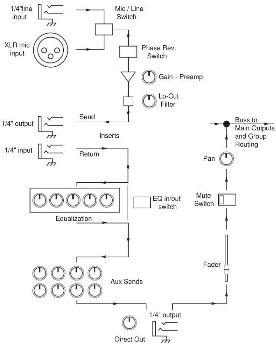
Recording and PA consoles operate at a nominal level of +4dBu, while microphones operate at a level of typically about -50dBu. Microphone signals must be amplified to the appropriate level for a console to process it properly. If a signal is not raised to the appropriate level, the signal will be “masked” by the console’s internal noise, especially when one tries to increase the level of a low signal using the console fader or gain knob. All consoles have a preamp (usually labeled “Gain”) as the first stage of an input strip, allowing the user to boost a signal to an appropriate level before the other processes of the input strip act upon the signal (EQ, dynamics, panning, etc.) Unfortunately, console preamp circuits are often not given enough room on the circuit board, or high-quality parts. It is for this reason that outboard preamps have become so popular. See Figure 1 below for a typical input strip’s signal flow.
flowchart
graph TD
    A["1/4" line input"] --> B["XLR mic input"]
    B --> C["Phase Rev. Switch"]
    C --> D["Gain - Preamp"]
    C --> E["Lo-Cut Filter"]
    F["1/4" output"] --> G["1/4" input"]
    G --> H["1/4" output"]
    H --> I["1/4" output"]
    I --> J["Aux Sends"]
    J --> K["AUX Sends"]
    K --> L["Direct Out"]
    L --> M["1/4" output"]
    N["Send"] --> O["Inserts"]
    P["Return"] --> Q["EQ in/out switch"]
    Q --> R["Equalization"]
    R --> S["Buss to Main Outputs and Group Routing"]
    T["Pan"] --> U["Mute Switch"]
    U --> V["Fader"]
    V --> W["AUX Sends"]
    X["Buss to Main Outputs and Group Routing"] --> Y["Buss to Main Outputs and Group Routing"]
Figure 1: Signal flow of Typical Console Input Strip.
The gain, or preamp stage occurs before all audio-critical processes act upon the incoming signal. The preamp's "color" is then processed as part of the signal.
The only processes ahead of the preamp stage are the input selection stage, and the phase reverse switch.
Connection
to your system
786
The 786 is the perfect partner for your microphone, providing you with two channels of audio purist quality preamplification. The 786 delivers up to 70dB of sonically transparent gain to reveal the detail and audio signature of even the most esoteric studio mics. It transforms their low level output signal to a clean high level, high current output for direct connection to the line level inputs of your mixer, DAT machine, sampler, or any other recording medium that accepts line level, analog input.
1. Bypassing a console's preamp with the 786.
- Mount the 786 in a 2U rack space. The 786 requires a two rack-space height and a standard 19 inch rack-space width. It can be mounted above or below anything that doesn't obstruct the vents of the 786. Ambient temperatures should not exceed 95^ (35°C) when equipment is powered.
- Make sure that AC power is not connected to your 786.
- Connect your mic cables to the audio inputs of the 786.
- Set the front panel of the 786 to the desired settings, including phantom power and Low-Z. Connect the audio output of the 786 to the console's LINE INPUT, and ensure that the console's input selection switch is set to LINE, and the console's gain control is set at its nominal operating level (ie: +4dBu).
NOTE: If you are using a mic with a separate power supply, such as a tube microphone, make sure that you are not sending +48V phantom power from the 786 to the mic. Use the +48V Phantom Power switch on the 786 for all other microphones which require phantom power.
- Turn the 786's large Gain control counter-clockwise to the +15dB position, and the Fine control to 0dB, and apply power to the 786. Make sure your console's gain slider is at approximately nominal level ("0dB") and begin to slowly increase the gain of the 786 using the large Gain control. You should increase the gain until the recording device is operating at nominal signal input level. Refer to Figure 2 below for hooking up the 786 to a console.
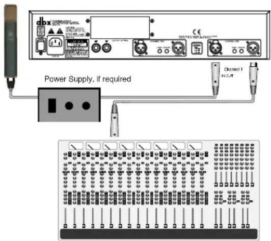
Figure 2: Bypassing a console's mic pre with the 786
2. Using the 786 to connect a mic directly to a recorder.
-
Make microphone connections as shown on the previous page, being careful to start with the Gain control in the +15dB position.
-
Connect the 786's audio outputs directly to the audio inputs of your recorder (see figure 3). This will require the disconnection of the console's audio output to the specific track of the recorder.
-
Enable the record function of the specific track of the recorder and open the specific tape track return in the console which corresponds to the track to which the 786 is connected. As you raise the Gain control, you should begin to hear the input of the 786 running through the recorder and returning to your console as a tape return.
NOTE: When recording in this way, you should use a compressor/limiter in the path before the recorder. The perfect companion product to the 786 is the dbx 160SL Stereo Compressor. Also, when recording with this method, remember that desired gain changes to the recorder can only be made via the GAIN controls of the 786. While this is much less convenient, it is often desirable to go directly to tape, bypassing all console electronics in favor of a pristine signal. A good compressor becomes vital to this process.
NOTE: For optimal performance, after applying power to the 786, let it sit for approximately 5 minutes before use, so that the internal DC servos can cancel any DC offsets.
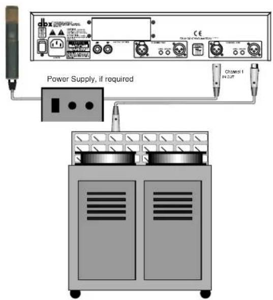
Figure 3: Connection of the 786 to a recorder. Note that the 786 may be connected to any recorder, from a large format analog recorder (shown) to a MDM such as an ADAT or DA-88.
Operating Controls
Front Panel

Gain Control
Use the Gain control to adjust the output level of the 786. Note that the Gain control is used as a “coarse” adjustment, ranging from +15dB to +65dB of gain, in 5dB increments. The Gain control is not a “pot”, or in other words, the signal does not go through this control. The Gain control is a relay-based system which “tells” the 786 how much gain should be applied to the signal. You should always set the Gain control to one of the detents. Do not set the Gain control between detents.
Fine Control
The Fine control further adjusts the gain in a sweepable fashion between -5dB and +5dB. If you set the Gain control to +45dB of coarse gain and the Fine control to -3dB of fine gain, your overall gain will be +42dB.
Spectrum Control
Use this control to set the frequency where the EQ section boosts or cuts 3dB. The range of this control is 5kHz to 40kHz. Obviously there is no fundamental frequency material at the 40kHz frequency, however, due to the slope of the EQ curve, frequencies in the audio range are affected. Also, boosting at this frequency emphasizes harmonic information that is sometimes referred to as “air” or “space” in the signal. This control is calibrated to the frequency at which 3dB of boost or cut occurs when the Detail control is set at +16dB or -16dB respectively.
Detail Control
This control adjusts the amount of boost or cut of the high frequency shelving EQ. The range is - to +16dB. “ - ” is typically better than -30dB. The cut and boost curves are symmetrical from 16dB boost to 16dB cut (ie: a 2dB boost produces a shelving curve that is the mirror image of the shelving curve produced by a 2dB cut). When the control is set to - , the band acts like a low pass filter whose slope is determined by the 12dB/OCT switch.
12dB/OCT Switch and LED
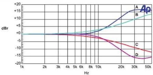
Engage this switch (the adjacent LED will light) to set the slope of the shelving curve to 12dB/Octave. Leaving the switch in the “out” position sets the slope to a gentler 6dB/Octave rate. For example, a 12dB setting for the slope can let you create a sense of “air” without the stridency caused by too much boosting of upper mid range frequencies. Figure 4 on the next page shows the behavior of the 786's EQ section.
HF EQ switch
The hardwired EQ in/out switch bypasses the EQ circuit in the audio path. Settings on the Detail and Spectrum controls, as well as the 12dB/Octave switch are nullified by disengaging the HF EQ switch.

line
| Hz | A | B | C | D | |------|-------|-------|-------|-------| | 1k | 0.0 | 0.0 | 0.0 | 0.0 | | 2k | -1.0 | -1.5 | -2.0 | -3.0 | | 3k | -2.5 | -3.0 | -4.0 | -6.0 | | 4k | -4.0 | -5.0 | -6.0 | -9.0 | | 5k | -6.0 | -7.0 | -8.0 | -12.0 | | 6k | -8.0 | -9.0 | -10.0 | -15.0 | | 8k | -10.0 | -11.0 | -12.0 | -18.0 | | 10k | -12.0 | -13.0 | -14.0 | -21.0 | | 20k | -15.0 | -16.0 | -17.0 | -25.0 | | 30k | -16.0 | -17.0 | -18.0 | -28.0 | | 50k | -17.0 | -18.0 | -19.0 | -30.0 |A: 16dB Cut @ 5kHz; 6dB/Octave Slope
B: 16dB Cut @ 5kHz; 12dB/Octave Slope
C: -ix: Cut @ 5kHz; 6dB/Octave Slope
D: -∞ Cut @ 5kHz; 12dB/Octave Slope
line
| Hz | A | B | C | D | |------|-------|-------|-------|-------| | 1k | -0.5 | -0.5 | -0.5 | -0.5 | | 2k | -0.5 | -0.5 | -0.5 | -0.5 | | 3k | -0.5 | -0.5 | -0.5 | -0.5 | | 4k | -0.5 | -0.5 | -0.5 | -0.5 | | 5k | -0.5 | -0.5 | -0.5 | -0.5 | | 6k | -0.5 | -0.5 | -0.5 | -0.5 | | 8k | -0.5 | -0.5 | -0.5 | -0.5 | | 10k | -0.5 | -0.5 | -0.5 | -0.5 | | 20k | +10 | +5 | -10 | -15 | | 30k | +15 | +10 | -12 | -18 | | 50k | +15 | +12 | -13 | -18 |A: 16dB Boost @ 12kHz; 12dB/Octave Slope
B: 16dB Boost @ 12kHz; 6dB/Octave Slope
C: 16dB Cut @ 12kHz; 6dB/Octave Slope
D: 16dB Cut @ 5kHz; 12dB/Octave Slope
Figure 4: Audio Precision plots of the 786's EQ section.
Peak LED
The Peak LED is located to the left of the VU Meter. It is set to light when the signal level is within 3dB of hard clipping. The LED monitors three different points in the signal path: output of the Gain control stage, the output of the Fine control stage, and the output of the EQ stage.
VU Meter
The VU Meter is a custom dbx meter and monitors the output signal of the 786. It is calibrated at 0VU=+4dBu.
+48V Phantom Power Switch and LED
This switch activates phantom power for condenser microphones on pins 2 and 3 of the XLR mic input. Make sure to connect your microphone before activating the phantom power to prevent high voltage arching, which may damage your microphone.
Super Low Z Input Switch and LED
Typically microphones have an output impedance of 150 . The 786 is set to operate in this range without any adjustments necessary. In some instances, a microphone may operate at a much lower impedance, like 20 . (ie: some ribbon microphones) The Super Low Z switch optimizes the input circuit of the 786 for proper damping of these low impedance microphones, and to ensure that the input transformer is always fed by the same impedance for consistent performance.
20dB Pad Switch and LED
This switch inserts a 20dB attenuator circuit into the signal path from the microphone input. The pad is inserted before the signal is routed through the mic pre gain stage. Use the 20dB pad to attenuate signals from hot sources such as high output microphones, or when the source is a line level device.
Phase Reverse Switch and LED
This switch inverts the phase of the input source 180^ . Note that it usually takes years of engineering experience to properly hear phase relationships. If your console has a phase relationship meter, you may choose to do “A-B” comparisons with the phase reverse switch in both positions for best results. Out of phase signals are more obvious in the lower frequency range, due to the size of the waveforms. Out of phase signals may sound “empty”, “hollow”, or “weak” in the low frequencies. Use the phase reverse switch to determine if the source device is out of phase with the rest of the program material.

Rear Panel
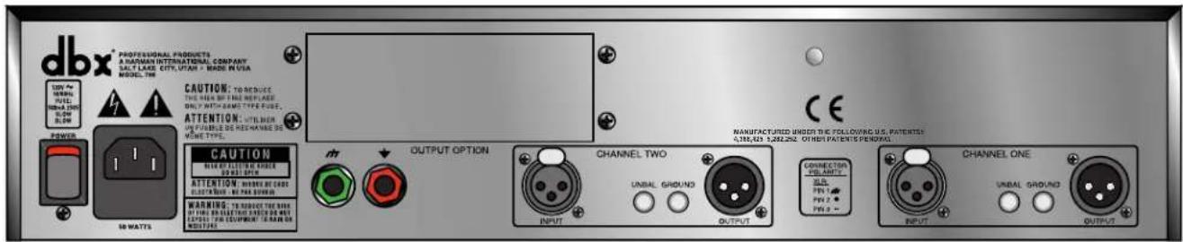
Audio Input and Output Connectors
Each audio input connector on the rear panel of the 786 is a gold-plated Neutrik® XLR female connector. The no-compromise approach to the 786 required that we use gold-plated connectors, due to their high conductivity and resistance to corrosion. The connectors are default wired in BALANCED mode (pin 2 hot, AES convention), although supplying an unbalanced signal presents no difficulty to the 786, (by grounding pin 3).
Unbalance Switch
The Unbalance switch is associated only with the Output connectors of the 786. When it is in the IN position, the output of the 786 is switched from balanced to unbalanced. (See Figure 5 on page 9.) In the OUT position, the 786's outputs are balanced in the "pin 2 hot" configuration. Note that when the output is unbalanced via the switch, there is a 6dB drop in output signal level, and the meter is still calibrated for a balanced signal.
Ground Switch
The Ground switch, when in the IN position, references the center tap of the output transformer to the chassis ground. The combination of the two switches associated with the audio output connectors ensures that the 786 is versatile enough to interface with any equipment and can deliver clean audio to the output, free of hum and interference. (See the Figure 5 for details of the Ground switch operation.)
Chassis Ground Binding Post ( )
The green Chassis Ground binding post is supplied to give the user another method to provide comprehensive grounding options for any installation. It is easy to think of the binding post as being synonymous with the ground pin on any AC power cord. (The ground pin on an AC cord should NEVER be removed, shorted out, or "lifted".) The post allows the chassis ground to be connected to another ground source if desired. (ie: a chassis ground system provided by another piece of gear) Wire may be connected to the binding post by securing the stripped end of the wire through the hole in the post, located under the hardened plastic nut-top of the post. Access to the hole is gained by unscrewing the top part of the post far enough to reveal the hole underneath. Insert the stripped end of the wire and tighten the top (nut) part of the binding post to secure the connection.
Signal Ground Binding Post (▼)
The black Signal Ground binding post is located next to the Chassis Ground binding post, and works in much the same way, providing comprehensive grounding options for any installation. Some systems are built on a “star” grounding principle, where all the signal grounds are brought directly to one central point and grounded to earth at the same location. The Signal Ground binding post allows easy access to the signal ground system of the 786 without having to remove the cover of the 786 and locate a good place to take the signal ground out of the box.
Figure 5: Ground/Unbalance switch operation.
Note: The shorting link between chassis ground and signal ground should be left installed, unless another grounding scheme is used.
1/4 Inch Anchor Bolt
We have provided a 1/4" anchor bolt on the rear panel of the 786 to aid in securing the unit in your rack. Since the 786 is a heavy unit, we recommend securing the 786 to a rear rack rail to avoid unnecessary stress on the front panel and front rack rails of your rack. The anchor bolt provides no electrical or audio benefit to the 786, and no grounding or electrical wires should be connected to it.
AC Power Switch
Located beside the AC Power connector, the AC Power switch turns the 786 ON and OFF. When the switch is in the DOWN position, revealing the red portion of the switch, the AC power to the 786 is ON. When the switch is in the UP position, no AC power is being supplied to the 786, regardless of other power connections.
AC Power Connector
The AC Power connector is a standard IEC 320 power inlet receptacle, for use with any IEC-type power cord (included with the 786). Connect this cable to any 50Hz or 60Hz AC power source of the correct line voltage for your area. Make sure this voltage is also correct for the voltage marked on the back of the 786. Always make AC power connections with the AC power switch in the OFF position (see above). The 786 consumes a maximum power of 50 watts.
Warning: Be sure to verify both your actual line voltage and the voltage for which your 786 is wired, as indicated on the back panel of the unit. Connection to an inappropriate power source may result in exten-
sive damage which is not covered by the warranty.
Output Option Panel
This panel is removed when an output option card is installed in your 786. Connecting a custom designed digital output module in the option port provides full 24-bit AES/EBU and S/PDIF output capabilities for the 786. The digital outputs of the 786 operate simultaneously with the analog outputs, providing the possibility of running to two different devices at the same time: analog, and AES/EBU or S/PDIF. For more information on the digital output option, contact dbx customer service. Be sure to fill out your warranty registration card, provided in this manual, and return it to dbx as soon as possible. This will enable us to notify you of other output options that will become available in the future.
Technical Support
If you require technical support, contact dbx Customer Service. Be prepared to accurately describe the problem. Know the serial number of your unit - this is printed on a sticker attached to the rear panel. If you have not already taken the time to fill out your warranty registration card and send it in, please do so now.
Factory Service
Before you return a product to the factory for service, we recommend you refer to the manual. Make sure you have correctly followed installation steps and operation procedures. If you are still unable to solve a problem, contact our Customer Service Department at (801) 568-7660 for consultation. If you need to return a product to the factory for service, you MUST contact Customer Service to obtain a Return Authorization Number.
No returned products will be accepted at the factory without a Return Authorization Number.
Please refer to the Warranty below, which extends to the first end-user. After expiration of the warranty, a reasonable charge will be made for parts, labor, and packing if you choose to use the factory service facility. In all cases, you are responsible for transportation charges to the factory. dbx will pay return shipping if the unit is still under warranty.
Use the original packing material if it is available. Mark the package with the name of the shipper, and with these words in red: DELICATE INSTRUMENT, FRAGILE! Insure the package properly. Ship prepaid, not collect. Do not ship parcel post.
Warranty
This warranty is valid only for the original purchaser and only in the United States.
- The warranty registration card that accompanies this product must be mailed within 30 days after purchase date to validate this warranty. Proof-of-purchase is considered to be the burden of the consumer.
- dbx warrants this product, when bought and used solely within the U.S., to be free from defects in materials and workmanship under normal use and service.
- dbx liability under this warranty is limited to repairing or, at our discretion, replacing defective materials that show evidence of defect, provided the product is returned to dbx WITH RETURN AUTHORIZATION from the factory, where all parts and labor will be covered up to a period of two years. A Return Authorization number must be obtained from dbx by telephone. The company shall not be liable for any consequential damage as a result of the product's use in any circuit or assembly.
- dbx reserves the right to make changes in design or make additions to or improvements upon this product without incurring any obligation to install the same additions or improvements on products previously manufactured.
- The foregoing is in lieu of all other warranties, expressed or implied, and dbx neither assumes nor authorizes any person to assume on its behalf any obligation or liability in connection with the sale of this product. In no event shall dbx or its dealers be liable for special or consequential damages or from any delay in the performance of this warranty due to causes beyond their control.
Specifications
INPUTS
Connectors: Female XLR Pin 2 hot.
Type: Transformer balanced/unbalanced.
Impedance: 1.44kΩ, 20 Hz to 20 kHz
Optimum Microphone Impedance: 150Ω or 20Ω with Super Low Z switch engaged.
Maximum Input Level: > +13 dBu or > +33 dBu with 20 dB pad engaged.
CMRR: > 115 dB at 60 Hz, > 110 dB at 1 kHz, > 75 dB at 10 kHz
CMRR with 10Ω imbalance
in one leg of input XLR with 150Ω
source impedance: > 90 dB at 60 Hz, > 65 dB at 1 kHz, > 55 dB at 10 kHz
OUTPUTS
Connectors: Male XLR Pin 2 hot.
Type: Transformer balanced/unbalanced, RF filtered.
Impedance: Balanced 40Ω, unbalanced 20Ω.
Maximum Output Level: Balanced typically +30 dBm (into 600Ω). Unbalanced (with UNBAL switch engaged) typically +24 dBm (into 600Ω).
SYSTEM PERFORMANCE
Course Gain Control: +15 dB to +65 dB voltage gain in 5 dB steps.
Fine Gain Control: Additional -5 dB to +5 dB voltage gain.
0.1 dB Bandwidth: 20 Hz to 20 kHz +0/-0.1 dB
Frequency Response: 2 Hz to 200 kHz +0/-3.0 dB
EIN: Typically -128 dBu, 150Ω source impedance, unweighted, 20 Hz to 20 kHz measurement bandwidth.
THD + Noise: 0.005% typical at +4 dBu out, 1kHz, 35 dB gain.
0.0009% typical at +24 dBu out, 1kHz, 35 dB gain.
<0.007% SMPTE 4:1, 35 dB gain.
IMD: <0.007% SMPTE 4:1, 35 dB gain.
Deviation From Linear Phase: < 2.0 degrees, 20 Hz to 20 kHz.
Interchannel Crosstalk: Typically -105 dB, 20 Hz to 20 kHz.
Specifications
786
EQUALIZER
Shelving Frequency: Sweepable from 5 kHz to 40 kHz.
Gain: Sweepable from -∞ to +16 dB.
Slope: Selectable; 6 dB/octave or 12 dB/octave.
FUNCTION SWITCHES
HF EQ: Enables high frequency shelving equalizer.
12 dB/OCT: Changes equalizer slope from 6 dB/octave to 12 dB/octave.
+48V: Sends regulated +48 VDC through 6.81kΩ 0.1% metal film resistors to pins 2 and 3 of the input XLR.
Super Low Z: Optimizes input stage for use with 20Ω low impedance microphones.
20 dB Pad: Attenuates the input signal by 20 dB.
∅ Invert: Reverses pins 2 and 3 of the input XLR connector.
Unbal (Rear Panel) Unbalances the output. A 6 dB drop in level will occur.
Ground (Rear Panel) In Balanced Mode: references the center tap of the output transformer to chassis ground through a 10kΩ resistor. In Unbalanced Mode: references pin 3 of the output XLR and the center tap of the transformer to chassis ground.
INDICATORS
HF EQ: Green LED to indicate when EQ is engaged.
12 dB/OCT: Yellow LED to indicated when 12 dB/octave mode is selected.
Peak: Red LED to indicated when signal is within 3 dB of clipping. Sense points are: output of M8 gain module (Course Gain), output of Fine Control, and output of equalizer section.
+48V: Red LED lights when phantom power is being delivered to input XLR connector.
Super Low Z: Yellow LED lights when Super Low Z mode is selected.
20 dB Pad: Green LED lights when 20 dB pad is engaged.
∅ Invert: Yellow LED lights when pins 2 and 3 of the input XLR are reversed.
Power: Blue LED lights to indicate the 786 is powered.
OPTIONS
Digital output module: Contact dbx for further details.
Analog output module: Contact dbx for further details.
POWER SUPPLY
Operating Voltage: 100VAC 50/60Hz
120VAC 60Hz
220-240VAC 50/60 Hz
Power Consumption: 50 Watts maximum.
Fuse: 100V: 500mA 250V Slow Blow 5mm X 20mm
120V: 500mA 250V Slow Blow 5mm X 20mm
220-240V: T250 mA 250V 5mm X 20mm
Mains Connection: IEC 320 Receptacle
PHYSICAL
Dimensions: 3.5" H X 19" W X 11.25" D
Weight: 20.5 lbs (9.3 kg)
Shipping Weight: 25.0 lbs (11.3 kg)
Note: 0 dBu = 0.775V RMS. Specifications are subject to change without notice.

flowchart
graph TD
    A["Input"] --> B["+48V"]
    B --> C["Relay"]
    C --> D["Relay"]
    D --> E["Relay"]
    E --> F["M8 Muc Pre Module"]
    F --> G["Jensen® JT-16-A"]
    G --> H["Gain Switching Relay Bank"]
    H --> I["Reclu + 15dB"]
    H --> J["Reclu + 20dB"]
    H --> K["..."]
    H --> L["Reclu + 65dB"]
    L --> M["Rectifier"]
    M --> N["RF Filter"]
    N --> O["Output"]
    P["Fine Gain"] --> Q["High Freq EQ"]
    Q --> R["Spectrum Detail"]
    S["Super Low Z 20dB Pad Phase Invert"] --> C
    T["Coarse Gain Rotaru Switch"] --> H
    U["Peak LED"] --> M
    V["HF EQ"] --> Q
    W["Jensen® Output Transformer"] --> N
    X["UrbalanceGround"] --> N
dbx®
PROFESSIONAL PRODUCTS
H A Harman International Company
8760 South Sandy Pkwy.
Sandy, Utah 84070
Phone: (801) 568-7660
Fax: (801) 568-7662
Int'l Fax: (603) 672-4246
Questions or comments?
E-mail us at: customer@dbxpro.com
or visit our World Wide Web home page at:
www.dbxpro.com

- PROFESSIONAL PRODUCTS
- 786
- Precision Mic Preamp
- WARNING
- FOR YOUR PROTECTION, PLEASE READ THE FOLLOWING:
- U.K. MAINS PLUG WARNING
- ELECTROMAGNETIC COMPATIBILITY
- SAFETY INSTRUCTIONS
- DECLARATION OF CONFORMITY
- Introduction 2
- Connection To Your System 4
- Operating Controls 6
- Technical Support/Factory Service 10
- Warranty 11
- Specifications 11
- Block Diagram 13
- Warranty Registration Card
- Introduction
- About mic preamps
- Understanding Console Signal Path
- Connection
- to your system
- Bypassing a console's preamp with the 786.
- Using the 786 to connect a mic directly to a recorder.
- Operating Controls
- Front Panel
- Gain Control
- Fine Control
- Spectrum Control
- Detail Control
- 12dB/OCT Switch and LED
- HF EQ switch
- Peak LED
- VU Meter
- +48V Phantom Power Switch and LED
- Super Low Z Input Switch and LED
- 20dB Pad Switch and LED
- Phase Reverse Switch and LED
- Audio Input and Output Connectors
- Unbalance Switch
- Ground Switch
- Chassis Ground Binding Post ( )
- Signal Ground Binding Post (▼)
- 1/4 Inch Anchor Bolt
- AC Power Switch
- AC Power Connector
- Output Option Panel
- Technical Support
- Factory Service
- No returned products will be accepted at the factory without a Return Authorization Number.
- Warranty
- Specifications
- INPUTS
- OUTPUTS
- SYSTEM PERFORMANCE
- EQUALIZER
- FUNCTION SWITCHES
- INDICATORS
- OPTIONS
- POWER SUPPLY
- PHYSICAL
- dbx®
- H A Harman International Company
Brand : DBX
Model : 786
Category : Receiver