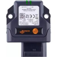
CR3132 - Industrial communication device IFM - Free user manual and instructions
Find the device manual for free CR3132 IFM in PDF.


User questions about CR3132 IFM
0 question about this device. Answer the ones you know or ask your own.
Ask a new question about this device
Download the instructions for your Industrial communication device in PDF format for free! Find your manual CR3132 - IFM and take your electronic device back in hand. On this page are published all the documents necessary for the use of your device. CR3132 by IFM.
USER MANUAL CR3132 IFM
Operating instructions
CANwireless
CR3132
Contents
1 Preliminary note 3
1.1 Symbols used 3
1.2 Warnings used 3
2 Safety instructions.... 4
2.1 Cyber security 4
2.2 Air traffic 4
3 Intended use.... 5
4 Function 6
4.1 CAN bridge via Bluetooth 6
4.2 CAN bridge via WLAN.... 6
4.3 CAN via Bluetooth interface 6
4.4 CAN via WLAN interface.... 6
5 Installation.... 7
5.1 Installation.... 7
6 Electrical connection.... 8
6.1 Connectors 8
6.1.1 Operating voltage, CAN interface, inputs and outputs 8
7 Light indicators 9
7.1 ON LED 9
7.2 STATUS LED 9
8 Set-up.... 11
8.1 Necessary components.... 11
8.2 Connecting the device.... 11
8.3 Configuration.... 11
8.3.1 CANopen 11
8.3.2 Communication settings 12
8.3.3 Rebooting the device 13
8.3.4 Factory reset.... 13
8.3.5 Filtering CAN messages 14
8.3.6 Filter functionality 15
8.3.7 Downsampling 17
8.3.8 Filter configuration.... 17
8.3.9 CAN - CAN bridge via Bluetooth 18
8.3.10 CAN - Mobile device / PC interface P2P Bluetooth 19
8.3.11 CAN - CAN bridge via WLAN Mini Access Point (MiniAP) mode.... 19
8.3.12 CAN - Mobile device / PC interface P2P WLAN Mini Access Point ..... 20
8.3.13 CAN - Mobile device / PC interface P2P WLAN infrastructure mode.... 21
8.3.14 Sleep mode.... 21
9 Repair, maintenance and disposal 23
1 Preliminary note
You will find instructions, technical data, approvals and further information using the QR code on the unit / packaging or at documentation.ifm.com.
1.1 Symbols used
√ Requirement
Instructions
Reaction, result
[...] Designation of keys, buttons or indications
→ Cross-reference

Important note
Non-compliance may result in malfunction or interference.

Information
Supplementary note
1.2 Warnings used
ATTENTION
Warning of damage to property

CAUTION
Warning of personal injury
▷ Slight reversible injuries may result.

WARNING
Warning of serious personal injury
▷ Death or serious irreversible injuries may result.
2 Safety instructions
- The unit described is a subcomponent for integration into a system.
- The system architect is responsible for the safety of the system.
-
The system architect undertakes to perform a risk assessment and to create documentation in accordance with legal and normative requirements to be provided to the operator and user of the system. This documentation must contain all necessary information and safety instructions for the operator, the user and, if applicable, for any service personnel authorised by the architect of the system.
-
Read this document before setting up the product and keep it during the entire service life.
- The product must be suitable for the corresponding applications and environmental conditions without any restrictions.
- Only use the product for its intended purpose (→ Intended use).
- If the operating instructions or the technical data are not adhered to, personal injury and/or damage to property may occur.
- The manufacturer assumes no liability or warranty for any consequences caused by tampering with the product or incorrect use by the operator.
• Installation, electrical connection, set-up, programming, configuration, operation and maintenance of the product must be carried out by personnel qualified and authorised for the respective activity. - Protect units and cables against damage.
- Replace damaged units, otherwise the technical data and safety will be impaired.
- Observe applicable documents.
2.1 Cyber security
ATTENTION
Operating the machine in an unprotected network environment
▷ Unauthorised read or write access to data is possible.
▷ Unauthorised manipulation of the device function is possible.
▶ Check and restrict access options to the device.
2.2 Air traffic
The device must not be operated on board aircraft.
Using it in an aircraft can affect the navigation and communication systems. An offence can lead to legal action against the offender.
3 Intended use
The device allows wireless transfer of CAN data of a vehicle or machine via a WLAN or a Bluetooth interface to another CANwireless device or to any Bluetooth device. Available modes are a CAN bridge to another machine or a direct wireless connection to any other device.
Available interfaces: Bluetooth and WLAN
4 Function
The device allows wireless access to the CAN interface of mobile machines for data exchange or error diagnostics.
The device has an internal antenna.
The parameters of the device are set via the CAN interface.
4.1 CAN bridge via Bluetooth
The CAN bridge via Bluetooth enables M2M (machine-to-machine) communication between two machines. The CANwireless devices connect via Bluetooth and exchange CAN messages. This replaces the physical CAN cable.
See also: CAN - CAN bridge via Bluetooth ( → ☐ 18)
Communication via Bluetooth is recommended because the Bluetooth frequency band is used significantly less than the WLAN frequency band. The connection between the machines is thus more stable and less disturbed.
4.2 CAN bridge via WLAN
The CAN bridge via WLAN enables M2M (machine-to-machine) communication between two machines. The CANwireless devices connect via WLAN and exchange CAN messages. This replaces the physical CAN cable.
See also: CAN - CAN bridge via WLAN Mini Access Point (MiniAP) mode ( → 19)
4.3 CAN via Bluetooth interface
Using the Bluetooth interface, the device can establish a connection to other Bluetooth devices such as smartphones, tablets or laptops. The CAN data is transferred to the connected device and can be stored and evaluated there. The CAN data is formatted with the Byte Command Protocol and then transmitted via Bluetooth. For more information about the byte protocol, see the document "Programming manual - API Description - Byte Command Protocol".
4.4 CAN via WLAN interface
Using the WLAN interface, the CANwireless device can establish a connection to other WLAN devices such as smartphones, tablets or laptops. The CAN data is transferred to the connected device and can be stored and evaluated there.
Using the CAN connection via the WLAN interface, two different operating modes (WLAN operating modes) are possible:
- Infrastructure In the operating mode “Infrastructure”, the CANwireless device connects to an already existing WLAN network. This can be a company network or an access point.
- Mini Access Point In the operating mode “Mini Access Point”, the device creates its own WLAN network to which other devices can connect to. The CANwireless device can handle and manage a maximum of seven simultaneous connections at a time.
In both operating modes, the CAN data is formatted with the Byte Command Protocol. For more information about the Byte Command Protocol, see the document "Programming manual - API Description - Byte Command Protocol".
5 Installation

▶ Disconnect the power of the machine before installation.

The device must be installed in a horizontal position. Installation with the connectors facing upwards or downwards is not permitted.
The device must be fixed with the rear facing the mounting surface.
ATTENTION
Higher impact stress > IK07
▷ Damage possible
▷ Protection rating and electrical protection might be impaired
▷ Risk of injury possible
▶ If necessary, the system creator must take external measures to protect the device depending on the requirements of the corresponding application.
▶ Replace damaged devices, otherwise the technical data and safety will be impaired.

Fig. 1: Holes for mounting
▶ Use 2 M6x30 cylinder head bolts to fix the device on an even surface. Tightening torque: 3.4 Nm ±10%
5.1 Installation
▶ When mounting the antennas in vehicles avoid the vicinity of fuel tanks, vessels with explosives or insufficiently screened electronic components ( → 2 Safety instructions).
▶ Position the antennas so that a permanent distance of min. 0.2 m from people is ensured during operation.
▶ Do not install the antennas in closed metal constructions such as the driver's cab.

Stable data transmission requires a good antenna signal. In case of problems change the position of the antennas or the mobile equipment if necessary.
6 Electrical connection
6.1 Connectors

1: Micro Timer II connector, 14-pin (CAN, supply, inputs, outputs)
6.1.1 Operating voltage, CAN interface, inputs and outputs

Fig. 2: Micro Timer II connector, 14-pin
1: VCC / terminal 30 (supply)
2: factory setting 1 (input)
3: GND / terminal 31 (supply)
4: analogue input 1
5: analogue input 2
6: not used
7: digital output
8: digital input / terminal 15 (input, ignition signal)
9: factory setting 2 (input)
10: GND / terminal 31 (supply)
11: CAN2_H (CAN interface 1 (high) bidirectional)
12: CAN2_L (CAN interface 1 (low) bidirectional)
13: CAN1_H (CAN interface 1 (high) bidirectional)
14: CAN1_L (CAN interface 1 (low) bidirectional)
7 Light indicators

1: ON LED
2: STATUS LED
7.1 ON LED
| Colour | State | Meaning |
| - | Off | The device is switched off or in sleep mode. |
| Green | Flashing slowly | The device is in update mode and ready to receive a firmware update. The ON and STATUS LEDs flash simultaneously. |
| Green | Flashing quickly | Firmware is being installed. The ON and STATUS LEDs flash simultaneously. |
| Green | On | The device is switched on. Terminal 30 voltage is in the permissible range. |
| Red | On | The device is switched on. Terminal 30 voltage is outside the permissible range. |
| Orange | On | ▷ The device is reset to factory settings. The ON and STATUS LEDs are lit simultaneously. |
| Turquoise | On | The radio module is being updated (via HTTP server). The ON and STATUS LEDs are lit simultaneously. |
| Magenta | On | Active connection with CANwireless configurator The ON and STATUS LEDs are lit simultaneously. |
Tab. 1: ON LED
7.2 STATUS LED
The STATUS LED indicates the operating status of the active connection.
| Colour | State | Meaning |
| - | Off | The device is switched off or in sleep mode. |
| Green | Flashes (200 ms on, 200 ms off, 200 ms on, 1000 ms off) | The device is initializing. |
| Green | Flashes (200 ms on, 200 ms off) | The device is ready for connection. |
| Green | On | The device has established a connection. The device functions reliably. |
| Green | Flashing slowly | The device is in update mode and ready to receive a firmware update. The ON and STATUS LEDs flash simultaneously. |
| Green | Flashing quickly | Firmware is being installed. The ON and STATUS LEDs flash simultaneously. |
| Blue | Flashing | Data is being transferred. |
| Blue | On | Wireless connection error. |
| Orange | Single flashing light | The device has received a CANopen SDO request. |
| Orange | On | Error CAN1 |
| Red | On | Error CAN2 |
| Turquoise | On | The radio module is being updated (via HTTP server). The ON and STATUS LEDs are lit simultaneously. |
| Magenta | On | Active connection with CANwireless configurator The ON and STATUS LEDs are lit simultaneously. |
Tab. 2: STATUS LED
8 Set-up
8.1 Necessary components
The following components are needed to configure and set up the device:
- Hardware
- CR3132
- connection cable
– voltage supply 8...32 V DC
- PC / notebook
- CAN / PC interface (e.g. CAN/RS232-USB interface CANfox, art. no. EC2112) and adapter cable for CANfox (art. no. EC2113) with CAN bus terminating resistors (2 x 120 Ω)
- Configuration software
- ifm Maintenance Tool
- mobileIoT device configuration addin for ifm Maintenance Tool
For details on how to configure the device, see the ifm Maintenance Tool documentation.
8.2 Connecting the device
▶ Ensure that the CAN bus is provided with 120 Ω terminating resistors.
▶ Connect the CAN/PC interface with the CAN adapter cable to the device and connect it to the PC.
▶ Connect the ground terminal of the power supply to CAN1-GND.
▶ Apply the supply voltage.
The following table provides an overview of some CAN baud rates in relation to the cable length:
| CAN baud rate | Cable length CAN bus |
| 800 kbit/s | 50 m |
| 500 kbit/s | 100 m |
| 250 kbit/s | 250 m |
| 125 kbit/s | 500 m |
| 50 kbit/s | 1000 m |
Tab. 3: CAN baud rate
8.3 Configuration
This chapter describes the configuration of the CANwireless device. The setup of the CAN interface and the settings of the different operating modes are presented.
8.3.1 CANopen
By default, the device is configured to receive CANopen messages such as Tx SDOs, Rx SDOs and error messages (EMCY). The device processes the messages without forwarding them via the wireless interface.
With the following object, this behaviour can be adjusted:
| Function | Index | Subindex | Description |
| Activate / deactivate CAN-open objects | 0x20F4 | 0x00 | This parameter defines whether the CANopen stack is activated or not:0: CANopen remains active during connection (default)1: The CANopen stack is disabled during connection. |

If the CANopen stack is disabled during a radio connection, the device CANNOT be configured.
These messages are not sent if the CANopen stack is disabled:
| Type | Index |
| Tx SDO 1 | 0x580 + Node ID |
| Rx SDO 1 | 0x600 + Node ID |
| Heartbeat / Bootup | 0x700 + Node ID |
| NMT | 0x000 |
CANopen configuration:
| Object | Index | Subindex | Data type | Configuration |
| Heartbeat message CAN1 | 0x4053 | 0x03 | Unsigned 16 | Time in milliseconds0: switch off |
| Boot up message CAN1 | 0x4054 | 0x03 | Unsigned 32 | Bit 0: NMT Boot up active0: no Boot up message1: send Boot up message |
| Send NMT start to all nodes at CAN bus CAN1 | 0x4055 | 0x03 | Unsigned 32 | Select NMT startup mode:0: automatic execution2: send automatic execution and “NMT start” to all node IDs |
Tab. 4: CAN1
8.3.2 Communication settings
| Object | Index | Subindex | Data type | Configuration |
| Node-ID CAN1 | 0x4050 | 0x03 | Unsigned 8 | Enter Node-ID CAN1 |
| Baudrate CAN1 | 0x4051 | 0x03 | Unsigned 8 | Baudrate in kbit/s:1: 8002: 5003: 250 (default)4: 1255: 1006: 507: 208: 10 |
Tab. 5: CAN1
| Object | Index | Subindex | Data type | Configuration |
| Node-ID CAN2 | 0x4050 | 0x04 | Unsigned 8 | Enter Node-ID CAN2 |
| Baudrate CAN2 | 0x4051 | 0x04 | Unsigned 8 | Baudrate in kbit/s:1: 8002: 5003: 250 (default)4: 1255: 1006: 507: 208: 10 |
Tab. 6: CAN2
8.3.3 Rebooting the device
| Object | Index | Subindex | Data type | Configuration |
| Device reboot | 0x5000 | 0x00 | Unsigned 32 | Value: 0x4E4D5481 |
Tab. 7: Reboot
8.3.4 Factory reset
The following reset variants can be triggered via the CAN interface:
| Function | Index | Subindex | Value / data type | Description |
| Reset device to factory settings | 0x1011 | 0x01 | 0x64616F6C / Unsigned 32 | The factory configuration is restored. All recorded data is deleted. |
| Reset communication parameters to factory settings | 0x1011 | 0x02 | 0x64616F6C / Unsigned 32 | The following parameters are reset to factory settings:- Node-ID CAN1: 33- Node-ID CAN2: 34- Baudrate CAN1: 3 (250 kbit/s)- Baudrate CAN2: 3 (250 kbit/s)- Heartbeat CAN1: 0 (no Heartbeat)- Heartbeat CAN2: 0 (no Heartbeat)- NMT Startup CAN1: 0 (automatically set to operational) |
| Reset parameters defined by the manufacturer to factory settings | 0x1011 | 0x19 | 0x64616F6C / Unsigned 32 | The following parameters are reset to factory settings:- CAN1 filter settings- CAN1 mask settings- CAN1 downsampling time |
To carry out the factory reset via the CAN interface, CANopen software (e.g. maintenance tool) and a communication gateway (e.g. CANfox, part no. EC2112) are required. The CANopen software writes the value 0x64616F6C into the CANopen object index 0x1011, subindex 0x01, to perform a complete reset.
The following example shows the factory reset via the subindex 0x01 (restoration of the default configuration):
▶ Connect the device with a PC Connecting the device ( → ☐ 11).
▶ Start the CANopen software.
▶ Write the value 0x64616F6C into the object index 0x1011, subindex 0x01 via the CANopen software.
▶ Write the value to the object directory of the device.
▷ The ON and STATUS LEDs both light orange.
▷ The device is reset to factory settings.
▶ Wait until the STATUS LED flashes green.
▷ The STATUS LED flashes green.
▷ The device is reset to factory settings.
8.3.5 Filtering CAN messages
You can configure in the device which CAN messages are forwarded from the CAN interface to the radio interface. The bus load of the CAN and radio interfaces is reduced if no more data than necessary is allowed.
A filter and a mask for the CAN ID decide whether a message is forwarded to the radio interface. Up to eight filters can be configured. If there are less than eight messages, a separate filter can be used for each message. Use mask 0x7FF for an 11-bit CAN ID and mask 0x1FFFFFFF for a 29-bit CAN ID.
The device uses the following variables to calculate whether to allow or block a CAN message:
| Variable name | Description |
| RxCANid | CAN ID of the received CAN message |
| Filter Value | Filter with which a CAN ID is identified as authorised |
| MaskValue | Mask with which a CAN ID is identified as authorised |
The verification mechanism works as follows:
RxCANid XOR Filter
Value = checkedCANid checkedCANid AND MaskValue = RESULT If RESULT = 0, the message is authorised.
Example 1:
RxCANid: 0x123
Filter
Value: 0x421
MaskValue: 0xF8
| Description | Hex | Binary |
| Received CAN message | 0x123 | 0b001.0010.0011 |
| Filter Value | 0x421 | 0b100.0010.0001 |
| XOR | ||
| checkedCANid | 0x502 | 0b101.0000.0010 |
| MaskValue | 0x0F8 | 0b000.1111.1000 |
| AND | ||
| RESULT | 0x000 | 0b000.0000.0000 |
→ With these settings, the CAN ID 0x123 is authorised; messages with this ID are forwarded.
Example 2:
RxCANid: 0x123
Filter
Value: 0x431
MaskValue: 0xF8
| Description | Hex | Binary |
| Received CAN message | 0x123 | 0b001.0010.0011 |
| Filter Value | 0x431 | 0b100.0011.0001 |
| XOR | ||
| checkedCANid | 0x512 | 0b101.0001.0010 |
| MaskValue | 0x0F8 | 0b000.1111.1000 |
| AND | ||
| RESULT | 0x010 | 0b000.0001.0000 |
→ With these settings, the CAN ID 0x123 is rejected; messages with this ID will not be forwarded.
8.3.6 Filter functionality
The filter set in the device consists of two components: the filter (Filter
Value) and the mask (MaskValue). With these two components, the device calculates which CAN IDs are permitted and will only forward these CAN messages to the radio interface.
You can determine the correct Filter
Value by ORing all desired CAN IDs.
You can determine the correct MaskValue by XNORing all desired CAN IDs.

The bigger the MaskValue, the stricter the filter works.
Zeros in the MaskValue have no influence on the result.
Example: MaskValue = 0x0F8 → 0b000.1111.1000 → 0bxxx.1111.1xxx
Only bit 3, bit 4, bit 5, bit 6 and bit 7 have an influence on the filter.
Example 1:
Only messages with CAN IDs 0x123, 0x124 and 0x125 are to be forwarded.
▶ Determine the Filter
Value:
| Description | Hex | Binary |
| Received CAN message 1 | 0x123 | 0b001.0010.0011 |
| Received CAN message 2 | 0x124 | 0b001.0010.0100 |
| Received CAN message 3 | 0x125 | 0b001.0010.0101 |
| OR | ||
| Required value for Filter Value | 0x127 | 0b001.0010.0111 |
▶ Determine the MaskValue:
| Description | Hex | Binary |
| Received CAN message 1 | 0x123 | 0b001.0010.0011 |
| Received CAN message 2 | 0x124 | 0b001.0010.0100 |
| Received CAN message 3 | 0x125 | 0b001.0010.0101 |
| XNOR | ||
| Required value for MaskValue | 0xFF8 | 1b111.1111.1000 |
▶ Test with CAN message 3:
| Description | Hex | Binary |
| Received CAN message 3 | 0x125 | 0b001.0010.0101 |
| Filter Value | 0x127 | 0b001.0010.0111 |
| XOR | ||
| checkedCANid | 0x002 | 0b000.0000.0010 |
| MaskValue | 0xFF8 | 1b111.1111.1000 |
| AND | ||
| RESULT | 0x000 | 0b000.0000.0000 |
→ CAN ID 0x125 is authorised; messages with this ID are forwarded.
Example 2:
Only messages with the CAN ID 0x123 are to be forwarded.
| Description | Hex | Binary |
| Received CAN message | 0x123 | 0b001.0010.0011 |
| Filter Value | 0x123 | 0b001.0010.0011 |
| XOR | ||
| checkedCANid | 0x000 | 0b000.0000.0000 |
| MaskValue | 0xFFFF | 1b111.1111.1111 |
| AND | ||
| RESULT | 0x000 | 0b000.0000.0000 |
→ Only CAN ID 0x125 is authorised; messages with this ID are forwarded.
→ All other received CAN messages are blocked and not forwarded.
If there are more than eight messages, the CAN IDs must be grouped and several IDs share one filter.
Example:
The following CAN IDs are to be forwarded to the radio interface:
0x10, 0x11, 0x12, 0x13 and 0x14
and
0x627, 0x628, 0x629
Two filters and masks should be used here, for the 0x1 IDs and the 0x62 IDs respectively.
| Description | Hex | Binary |
| 0x10 | 0b001.0000 | |
| 0x11 | 0b001.0001 | |
| 0x12 | 0b001.0010 | |
| 0x13 | 0b001.0011 | |
| 0x14 | 0b001.0100 | |
| OR | ||
| Filter Value 1 | 0x17 | 0b001.0111 |
| Description | Hex | Binary |
| 0x10 | 0b001.0000 | |
| 0x11 | 0b001.0001 | |
| 0x12 | 0b001.0010 | |
| 0x13 | 0b001.0011 | |
| 0x14 | 0b001.0100 | |
| XNOR | ||
| MaskValue 1 | 0xF8 | 1b111.1000 |
| Description | Hex | Binary |
| 0x627 | 0b110.0010.0111 | |
| 0x628 | 0b110.0010.1000 | |
| 0x629 | 0b110.0010.1001 | |
| OR | ||
| Filter Value 2 | 0x62F | 0b110.0010.1111 |
| Description | Hex | Binary |
| 0x627 | 0b110.0010.0111 | |
| 0x628 | 0b110.0010.1000 | |
| 0x629 | 0b110.0010.1001 | |
| XNOR | ||
| MaskValue 2 | 0xFF0 | 1b111.1111.0000 |
8.3.7 Downsampling
The downsampling time can be used to reduce the number of messages via the radio interface. It is configured in 10 ms intervals. According to the configured value (e.g. 20), the reception and transmission of CAN messages is delayed (20 x 10 ms = 200 ms). A value of 0 disables the delay.

Only use downsampling with filters for individual CAN IDs to avoid data loss.
8.3.8 Filter configuration
Using the calculated Filter
Values and MaskValues and the desired downsampling times, the filters can be configured via corresponding SDOs:
| Function | Index | Subindex | Description |
| Filter setting (Filter Value) non-volatile | 0x5020 | 0x01...0x08 | Non-volatile object in which the Filter Value for the eight filters is configured. After restarting the device, these values are copied into the volatile object that controls the filter. The filter is only active when the radio interface is active. Bit-31 = 0 This filter setting is active and used by the filter. Bit-31 = 1 This filter setting is not active. Bit-29 = 011-bit CAN IDBit-29 = 129-bit CAN ID |
| Filter setting (Filter Value) volatile | 0x5021 | 0x01...0x08 | Volatile object in which the Filter Value for the eight filters is configured. This setting is taken over directly from the filter and can be adjusted dynamically. The filter is only active when the radio interface is active. Bit-31 = 0 This filter setting is active and used by the filter. Bit-31 = 1 This filter setting is not active. Bit-29 = 011-bit CAN IDBit-29 = 129-bit CAN ID |
| Mask setting (MaskValue) non-volatile | 0x5022 | 0x01...0x08 | Non-volatile object in which the MaskValue for the eight filters is configured. After restarting the device, these values are copied into the volatile object that controls the filter. The filter is only active when the radio interface is active. Bit 0...28 = MaskValue Bit 29...31 = not used → set to 0. Bit = 0: has no filter effect on the corresponding binary digit. Bit = 1: The corresponding bit of the received CAN ID and the Filter Value must match. |
| Mask setting (MaskValue) volatile | 0x5023 | 0x01...0x08 | Volatile object in which the MaskValue for the eight filters is configured. This setting is taken over directly from the filter and can be adjusted dynamically. The filter is only active when the radio interface is active. Bit 0...28 = MaskValue Bit 29...31 = not used → set to 0. Bit = 0: has no filter effect on the corresponding binary digit. Bit = 1: The corresponding bit of the received CAN ID and the Filter Value must match. |
| Downsampling non-volatile | 0x5024 | 0x01...0x08 | Non-volatile object in which the downsampling for the eight filters is configured. After restarting the device, these values are copied into the volatile object that controls the filter. This time must elapse before another CAN message is received that matches the corresponding filter. If this value is set to 0, every message that corresponds with the filter is received. |
| Downsampling volatile | 0x5025 | 0x01...0x08 | Volatile object in which the downsampling for the eight filters is configured. This setting is taken over directly from the filter and can be adjusted dynamically. This time must elapse before another CAN message is received that matches the corresponding filter. If this value is set to 0, every message that corresponds with the filter is received. |
8.3.9 CAN - CAN bridge via Bluetooth
In this mode, a wireless connection (CAN bridge) is established between two CANwireless devices via Bluetooth. The devices need to be configured as follows:
| Object | Index | Subindex | Data type | Configuration |
| WLAN Enable | 0x3008 | 0x02 | Unsigned 8 | 0: switch off |
| Bluetooth Enable | 0x3008 | 0x03 | Unsigned 8 | 1: switch on |
| Bluetooth Devicename | 0x3002 | 0x05 | Visible_string | Enter a unique name |
| Bluetooth Discoverable | 0x3002 | 0x01 | Unsigned 8 | 1: switch on |
| Bluetooth Pairable | 0x3002 | 0x02 | Unsigned 8 | 1: switch on |
| Security mode Blue-tooth 2.1 | 0x3002 | 0x03 | Unsigned 8 | 0: switch off |
| Bluetooth PIN | 0x3002 | 0x06 | Visible_string | Enter four-digit PINDefault: 0000 |
| Server Enable | 0x3010 | 0x15 | Unsigned 8 | 2: switch on server |
| Server Type | 0x3010 | 0x16 | Unsigned 8 | 2: SPP (Default) |
Tab. 8: Bluetooth server
| Object | Index | Subindex | Data type | Configuration |
| WLAN Enable | 0x3008 | 0x02 | Unsigned 8 | 0: switch off |
| Bluetooth Enable | 0x3008 | 0x03 | Unsigned 8 | 1: switch on |
| Bluetooth Devicename | 0x3002 | 0x05 | Visible_string | Enter a unique name |
| Bluetooth Discoverable | 0x3002 | 0x01 | Unsigned 8 | 1: switch on |
| Bluetooth Pairable | 0x3002 | 0x02 | Unsigned 8 | 1: switch on |
| Security mode Blue-tooth 2.1 | 0x3002 | 0x03 | Unsigned 8 | 0: switch off |
| Bluetooth PIN | 0x3002 | 0x06 | Visible_string | Enter four-digit PINDefault: 0000 |
| Client Enable | 0x3010 | 0x15 | Unsigned 8 | 3: switch on Client |
| Server Type | 0x3010 | 0x16 | Unsigned 8 | 2: SPP (Default) |
| Bluetooth SPP MAC | 0x3010 | 0x1a | Visible_string | Enter master MAC address |
Tab. 9: Bluetooth client
8.3.10 CAN - Mobile device / PC interface P2P Bluetooth
In this mode, a wireless connection is established between a CANwireless device and any other Bluetooth device via Bluetooth. The CANwireless device needs to be configured as follows:
| Object | Index | Subindex | Data type | Configuration |
| WLAN Enable | 0x3008 | 0x02 | Unsigned 8 | 0: switch off |
| Bluetooth Enable | 0x3008 | 0x03 | Unsigned 8 | 1: switch on |
| Bluetooth Devicename | 0x3002 | 0x05 | Visible_string | Enter a unique name |
| Bluetooth Discoverable | 0x3002 | 0x01 | Unsigned 8 | 1: switch on |
| Bluetooth Pairable | 0x3002 | 0x02 | Unsigned 8 | 1: switch on |
| Security mode Blue-tooth 2.1 | 0x3002 | 0x03 | Unsigned 8 | 0: switch off |
| Bluetooth PIN | 0x3002 | 0x06 | Visible_string | Enter four-digit PINDefault: 0000 |
| Server Enable | 0x3010 | 0x15 | Unsigned 8 | 2: switch on server |
| Server Type | 0x3010 | 0x16 | Unsigned 8 | 2: SPP (Default) |
8.3.11 CAN - CAN bridge via WLAN Mini Access Point (MiniAP) mode
In this mode, a wireless connection (CAN bridge) is established between two CANwireless devices via WLAN. The devices need to be configured as follows:
| Object | Index | Subindex | Data type | Configuration |
| Bluetooth Enable | 0x3008 | 0x03 | Unsigned 8 | 0: switch off |
| WLAN Enable | 0x3008 | 0x02 | Unsigned 8 | 1: switch on |
| WLAN Operating Mode | 0x3000 | 0x01 | Unsigned 8 | 2: Mini Access Point (Default) |
| SSID | 0x3000 | 0x02 | Visible_string | Enter a unique name for the WLAN network |
| Authentication Type | 0x3000 | 0x04 | Unsigned 8 | 7: WPA/WPA2 Mixed |
| Authentication Key | 0x3000 | 0x05 | Visible_String | Enter a secure authentication key with at least 8 characters |
| DHCP | 0x3000 | 0x09 | Unsigned 8 | 2: server (Default)(only for WLAN MiniAP) |
| Hostname | 0x3005 | 0x01 | Visible_string | Enter a unique device name. |
| IP address | 0x3000 | 0x0a | Visible_string | 192.168.82.34 |
| Network mask | 0x3000 | 0x0b | Visible_string | 255.255.255.0 |
| Gateway address | 0x3000 | 0x0c | Visible_string | 192.168.82.1 |
| Primary DNS Server | 0x3000 | 0x0d | Visible_string | 192.168.82.1 |
| Secondary DNS Server | 0x3000 | 0x0e | Visible_string | 192.168.82.2 |
| Server Enable | 0x3010 | 0x15 | Unsigned 8 | 2: switch on server |
| Server Type | 0x3010 | 0x16 | Unsigned 8 | 1: socket (TCP/UDP) |
| Server Type | 0x3010 | 0x18 | Unsigned 16 | 30000 (Default) |
Tab. 10: WLAN server (Mini Access Point)
| Object | Index | Subindex | Data type | Configuration |
| Bluetooth Enable | 0x3008 | 0x03 | Unsigned 8 | 0: switch off |
| WLAN Enable | 0x3008 | 0x02 | Unsigned 8 | 1: switch on |
| WLAN Operating Mode | 0x3000 | 0x01 | Unsigned 8 | 1: infrastructure |
| SSID | 0x3000 | 0x02 | Visible_string | Enter the SSID of the WLAN network |
| Authentication Type | 0x3000 | 0x04 | Unsigned 8 | 7: WPA/WPA2 Mixed |
| Authentication Key | 0x3000 | 0x05 | Visible_String | Enter the authentication key of the WLAN network |
| DHCP | 0x3000 | 0x09 | Unsigned 8 | 1: Client(only for WLAN infrastructure) |
| Hostname | 0x3005 | 0x01 | Visible_string | Enter a unique device name. |
| Client Enable | 0x3010 | 0x15 | Unsigned 8 | 3: switch on Client |
| Server Type | 0x3010 | 0x16 | Unsigned 8 | 1: socket (TCP/UDP) |
| Server Type | 0x3010 | 0x18 | Unsigned 16 | 30000 (Default) |
| EEP URL Address/WLAN Client only 1 | 0x3010 | 0x17 | Visible_string | Enter the IP address of the WLAN MiniAP |
Tab. 11: WLAN client (infrastructure)
8.3.12 CAN - Mobile device / PC interface P2P WLAN Mini Access Point
In this mode, a wireless connection is established between a CANwireless device and any other WLAN-enabled device via WLAN. The CANwireless device needs to be configured as follows:
| Object | Index | Subindex | Data type | Configuration |
| Bluetooth Enable | 0x3008 | 0x03 | Unsigned 8 | 0: switch off |
| WLAN Enable | 0x3008 | 0x02 | Unsigned 8 | 1: switch on |
| WLAN Operating Mode | 0x3000 | 0x01 | Unsigned 8 | 2: Mini Access Point (Default) |
| SSID | 0x3000 | 0x02 | Visible_string | Enter a unique name for the WLAN network |
| Authentication Type | 0x3000 | 0x04 | Unsigned 8 | 7: WPA/WPA2 Mixed |
| Authentication Key | 0x3000 | 0x05 | Visible_String | Enter a secure authentication key with at least 8 characters |
| DHCP | 0x3000 | 0x09 | Unsigned 8 | 2: server (Default)(only for WLAN MiniAP) |
| Hostname | 0x3005 | 0x01 | Visible_string | Enter a unique device name. |
| IP address | 0x3000 | 0x0a | Visible_string | 192.168.82.34 |
| Network mask | 0x3000 | 0x0b | Visible_string | 255.255.255.0 |
| Gateway address | 0x3000 | 0x0c | Visible_string | 192.168.82.1 |
| Primary DNS Server | 0x3000 | 0x0d | Visible_string | 192.168.82.1 |
| Secondary DNS Server | 0x3000 | 0x0e | Visible_string | 192.168.82.2 |
| Server Enable | 0x3010 | 0x15 | Unsigned 8 | 2: switch on server |
| Server Type | 0x3010 | 0x16 | Unsigned 8 | 1: socket (TCP/UDP) |
| Server Type | 0x3010 | 0x18 | Unsigned 16 | 30000 (Default) |
8.3.13 CAN - Mobile device / PC interface P2P WLAN infrastructure mode
In this mode, a wireless connection is established between a CANwireless device and any other WLAN-enabled device via WLAN. The CANwireless device needs to be configured as follows:
| Object | Index | Subindex | Data type | Configuration |
| Bluetooth Enable | 0x3008 | 0x03 | Unsigned 8 | 0: switch off |
| WLAN Enable | 0x3008 | 0x02 | Unsigned 8 | 1: switch on |
| WLAN Operating Mode | 0x3000 | 0x01 | Unsigned 8 | 1: infrastructure |
| SSID | 0x3000 | 0x02 | Visible_string | Enter the SSID of the WLAN network |
| Authentication Type | 0x3000 | 0x04 | Unsigned 8 | 7: WPA/WPA2 Mixed |
| Authentication Key | 0x3000 | 0x05 | Visible_String | Enter the authentication key of the WLAN network |
| DHCP | 0x3000 | 0x09 | Unsigned 8 | 1: Client(only for WLAN infrastructure) |
| Hostname | 0x3005 | 0x01 | Visible_string | Enter a unique device name. |
| Client Enable | 0x3010 | 0x15 | Unsigned 8 | 3: switch on Client |
| Server Type | 0x3010 | 0x16 | Unsigned 8 | 1: socket (TCP/UDP) |
| Server Type | 0x3010 | 0x18 | Unsigned 16 | 30000 (Default) |
| EEP URL Address/WLAN Client only 1 | 0x3010 | 0x17 | Visible_string | Enter the IP address of the WLAN MiniAP |
8.3.14 Sleep mode
The device features a sleep mode to save energy during inactive states.
The following events can trigger the sleep mode:
• no voltage at terminal 15 within a defined time period
• no reception of CAN messages within a defined time period
The sleep mode is configured as follows:
| Object | Index | Subindex | Data type | Configuration |
| PMM Shutdown Delay Time non-volatile | 0x3333 | 0x32 | Unsigned 16 | Time in seconds After terminal 15 is switched off, the device continues to operate for the time configured here and then goes into sleep mode. Default: 60 sThis function is only active if bit 7 is set for “PMM Wakeup enable flags”. |
| PMM Wakeup enable flagsnon-volatile | 0x3333 | 0x37 | Unsigned 8 | Enable activation of sleep mode via terminal 15. Bits 0...6: Reserved → set to 0. Bit 7: 1 → Monitoring of terminal 15 for sleep mode active Default: 0 |
| PMM Shutdown time-outnon-volatile | 0x3333 | 0x40 | Unsigned 32 | Time in millisecondsIf the prerequisites for the sleep mode are met, it will be enforced when this time has elapsed. This ensures switchover to sleep mode even if the regular activation of this mode should fail. Default: 60000 |
| PMM Sleep on no CAN timenon-volatile | 0x3333 | 0x41 | Unsigned 32 | Time in millisecondsIf the device does not receive any CAN messages within this time period, it goes to sleep mode. Default: 0 (function deactivated) |
9 Repair, maintenance and disposal
The unit is maintenance-free.
▶ Contact ifm in case of malfunction.
▶ Do not open the housing as the unit does not contain any components which can be maintained by the user. The unit must only be repaired by the manufacturer.
▶ Clean the device using a dry cloth.
▶ Dispose of the unit in accordance with the national environmental regulations.
- 1 PRELIMINARY NOTE
- 1.1 SYMBOLS USED
- 1.2 WARNINGS USED
- 2 SAFETY INSTRUCTIONS
- 2.1 CYBER SECURITY
- 2.2 AIR TRAFFIC
- 3 INTENDED USE
- 4 FUNCTION
- 4.1 CAN BRIDGE VIA BLUETOOTH
- 4.2 CAN BRIDGE VIA WLAN
- 4.3 CAN VIA BLUETOOTH INTERFACE
- 4.4 CAN VIA WLAN INTERFACE
- 5 INSTALLATION
- 5.1 INSTALLATION
- 6 ELECTRICAL CONNECTION
- 6.1 CONNECTORS
- 6.1.1 OPERATING VOLTAGE, CAN INTERFACE, INPUTS AND OUTPUTS
- 7 LIGHT INDICATORS
- 7.1 ON LED
- 7.2 STATUS LED
- 8 SET-UP
- 8.1 NECESSARY COMPONENTS
- 8.2 CONNECTING THE DEVICE
- 8.3 CONFIGURATION
- 8.3.1 CANOPEN
- 8.3.2 COMMUNICATION SETTINGS
- 8.3.3 REBOOTING THE DEVICE
- 8.3.4 FACTORY RESET
- 8.3.5 FILTERING CAN MESSAGES
- 8.3.6 FILTER FUNCTIONALITY
- 8.3.7 DOWNSAMPLING
- 8.3.8 FILTER CONFIGURATION
- 8.3.9 CAN - CAN BRIDGE VIA BLUETOOTH
- 8.3.10 CAN - MOBILE DEVICE / PC INTERFACE P2P BLUETOOTH
- 8.3.11 CAN - CAN BRIDGE VIA WLAN MINI ACCESS POINT (MINIAP) MODE
- 8.3.12 CAN - MOBILE DEVICE / PC INTERFACE P2P WLAN MINI ACCESS POINT
- 8.3.13 CAN - MOBILE DEVICE / PC INTERFACE P2P WLAN INFRASTRUCTURE MODE
- 8.3.14 SLEEP MODE
- 9 REPAIR, MAINTENANCE AND DISPOSAL
Brand : IFM
Model : CR3132
Category : Industrial communication device