
BOXI 955 000 SM - Cooker AMICA - Free user manual and instructions
Find the device manual for free BOXI 955 000 SM AMICA in PDF.
| Product type | Built-in electric cooker |
| Brand | Amica |
| Model | BOXI 955 000 SM |
| Dimensions (W×H×D) | 59.5 × 59.5 × 57.5 cm |
| Rated voltage | 230 V ~ 50 Hz |
| Max. rated power | 3.6 kW |
| Power supply type | Single-phase, earthed plug |
| Cooking functions | Fast heating, defrosting, reinforced grill, grill, fan oven, bottom/top heat, ECO fan oven, fan + heating elements |
| Programmer | Touch electronic with timer, delayed start, automatic shut-off |
| Oven lighting | 25 W bulb, E14 base (or G9 halogen depending on version) |
| Cleaning | Steam cleaning (Steam Clean); removable door, removable inner glass, removable side racks |
| Safety | Door lock, control indicators, automatic shut-off, hot surface warning |
| Materials | Steel, glass, enamel |
| Energy class | Defined according to ECO function: ECO fan oven, ECO conventional mode |
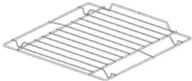
| Included accessories | Grid, drip tray, bread pan (depending on model) |
| Repairability | Bulb and glass replaceable by user; other repairs by approved after-sales service |
Frequently Asked Questions - BOXI 955 000 SM AMICA
User questions about BOXI 955 000 SM AMICA
0 question about this device. Answer the ones you know or ask your own.
Ask a new question about this device
Download the instructions for your Cooker in PDF format for free! Find your manual BOXI 955 000 SM - AMICA and take your electronic device back in hand. On this page are published all the documents necessary for the use of your device. BOXI 955 000 SM by AMICA.
USER MANUAL BOXI 955 000 SM AMICA
natural_image
Line drawing of a standard open oven with control panel and door (no text or symbols)12223.3eEHpTsDpHbScX / BOXC 954 000 E
12223.3eEHpTsDpHbScX / BOXI 955 000 E
12223.3eEHpTsDpHbScSm / BOXC 954 000 SM
12223.3eEHpTsDpHbScSm / BOXI 955 000 SM
natural_image
Simple black-and-white line drawing of a tree with two wavy lines at the base (no text or symbols)natural_image
Isometric line drawing of a square frame with rounded corners and a small central hole (no text or symbols)Backblech*
natural_image
Technical line drawing of a rectangular metal grate or rack structure (no text or symbols)natural_image
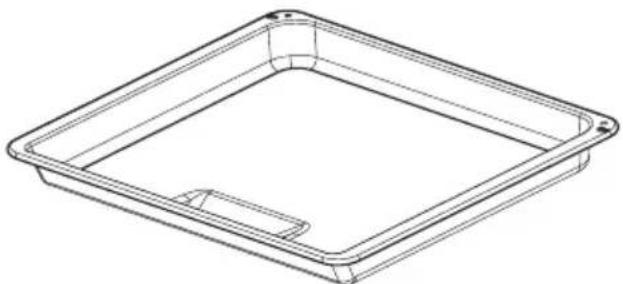
Line drawing of a rectangular tray or container with a recessed slot (no text or symbols)Bratblech*
natural_image
Top-down schematic of a rectangular device with internal components and directional arrows (no text or symbols)Achtung!
natural_image
Simple line drawing of a curved arrow with a diagonal line, no text or symbols present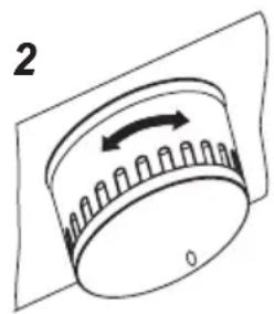
text_image
2 0Wichtig!
text_image
Diagram illustrating the process of temperature change in a circular device, showing step-by-step rotation and adjustment.natural_image
Technical line drawing of a microwave oven with internal grid pattern and control knob (no text or symbols)natural_image
Technical line drawing of a microwave oven with internal grid pattern and control knob (no text or symbols)natural_image
Three diagrams showing mechanical or electrical components with arrows indicating motion, no text or symbols present.natural_image
Diagram showing three stages of a mechanical or electrical device with rotating components and directional arrows (no text or symbols)natural_image
Technical line drawing of a mechanical assembly with an inset showing a close-up of a component (no text or symbols present)natural_image
Technical line drawing of a mechanical assembly with a rectangular frame and a separate cylindrical component (no text or symbols)natural_image
Simple black-and-white line drawing of a tree with cloud-like canopy and two wavy lines at the base (no text or symbols)natural_image
Simple line drawing of a recycling symbol (three chasing arrows), no text or labels present.natural_image
Isometric line drawing of a square frame with rounded corners and mounting holes (no text or symbols)natural_image
Isometric line drawing of a rectangular metal grate or rack structure with no text or symbols(grille à gratiner)
natural_image
Line drawing of a rectangular tray with a recessed slot (no text or symbols)Plat à rôtissage*
natural_image
Technical line drawing of a cabinet or enclosure with internal compartments and ventilation grilles (no text or symbols)natural_image
Technical diagram of a square enclosure with internal grid pattern and directional arrows (no text or symbols)natural_image
Diagram of a rotary knob with directional arrow, no text or symbols presenttext_image
Diagram illustrating the process of temperature change in a circular device, showing step-by-step rotation and adjustment.natural_image
Technical diagram of a microwave oven with internal grid pattern and control knob (no text or symbols)Lampe du four
natural_image
Technical line drawing of a microwave oven with internal grid pattern and control knob (no text or symbols)Lampe du four
text_image
Diagram illustrating three stages of battery charging and discharging process with arrows indicating directionnatural_image
Diagram showing three sequential mechanical or electrical assembly steps with rotating components (no text or symbols)natural_image
Technical line drawing of a mechanical assembly with an inset showing a component detail (no text or symbols)natural_image
Technical line drawing of a mechanical assembly with a rectangular frame and a separate cylindrical component (no text or symbols)NETTOYAGE ET ENTRETIEN DE LA CUISINIÈRE
The Ground Truth image displays a single, solid horizontal line, which is a stylistic or background element (like a rule line on paper). According to Rule 2, such lines must be ignored by the OCR result. The OCR content provided is "", which consists of no characters. Since the OCR output correctly ignores the stylistic line, it complies with Rule 2. Therefore, the OCR result is consistent with the Ground Truth.
natural_image
Simple geometric diagram with circles and rectangles, no text or symbols presentPG4VI525FTB4SC / BOXI 955 000 E
(EN) INSTRUCTION MANUAL....2
(NL) GEBRUIKERSHANDLEIDING....33
Your hob combines exceptional ease of use with excellent effectiveness. Once you have read the instructions, operating your hob will not be a problem.
Before being packed and leaving the factory, the safety and functions of this hob were carefully tested.
We ask you to read the User Manual carefully before switching on the appliance. Following the directions in this manual will protect you from any misuse.
Keep this User Manual and store it near at hand.
The instructions should be followed carefully to avoid any unfortunate accidents.
Important!
The appliance may only be operated when you have read and understood this manual thoroughly.
The appliance is designed solely for cooking. Any other use (eg heating a room) is incompatible with the appliance's intended purpose and can pose a risk to the user. The manufacturer reserves the right to introduce changes which do not affect the operation of the appliance.
CONTENTS
Basic Information....2
Safety instructions....4
Description of the appliance....9
Installation....10
Operation....16
Cleaning and maintenance....28
Troubleshooting....30
Specification....32
Warning: The appliance and its accessible parts become hot during use. Care should be taken to avoid touching heating elements. Children less than 8 years of age shall be kept away unless continuously supervised.
This appliance can be used by children aged from 8 years and above and persons with reduced physical, sensory or mental capabilities or lack of experience and knowledge if they have been given supervision or instruction concerning use of the appliance in a safe way and understand the hazards involved. Children shall not play with the appliance. Cleaning and user maintenance shall not be made by children without supervision.
Warning: Unattended cooking on a hob with fat or oil can be dangerous and may result in fire.
NEVER try to extinguish a fire with water, but switch off the appliance and then cover flame e.g. with a lid or a fire blanket.
Warning: Danger of fire: do not store items on the cooking surfaces.
Warning: If the surface is cracked, switch off the appliance to avoid the possibility of electric shock.
Metallic objects, such as knives, forks, spoons and lids should not be placed on the hob surface since they can get hot.
After use, switch off the hob element by its control and do not rely on the pan detector.
The appliance is not intended to be operated by means of an external timer or separate remote-control system.
You should not use steam cleaning devices to clean the appliance.
- Before using the induction hob for the first time, carefully read its user manual. This will ensure user safety and prevent damage to the appliance.
- If the induction hob is operated in immediate vicinity to the radio, television set or other radio-frequency-emitting device, make sure that the hob's touch sensor controls operate correctly.
- The hob must be connected by a qualified installer.
- Do not install the appliance near a refrigerator.
- Furniture, where the hob is installed must be resistant to temperatures up to 100^ C. This applies to veneers, edges, surfaces made of plastics, adhesives and paints.
- The appliance may only be used once fitted in kitchen furniture. This will protect the user against accidental touching the live part.
- Repairs to electrical appliances may only be conducted by specialists. Improper repairs can be dangerous to the user.
- The appliance is not connected to mains when it is unplugged or the main circuit breaker is switched off.
- Plug of the power cord should be accessible after appliance has been installed.
- Ensure that children do not play with the appliance.
- This appliance is not intended for use by persons (including children) with physical, mental or sensory handicaps, or by those who are inexperienced or unfamiliar with the appliance, unless under supervision or in accordance with the instructions as communicated to them by persons responsible for their safety.
- Persons with implanted devices, which support vital functions (eg, pacemaker, insulin pump, or hearing aids) must ensure that these devices are not affected by the induction hob (the frequency of the induction hob is 20-50 kHz).
- Once power is disconnected all settings and indications are erased. When electric power is restored caution is advisable. If the cooking zones are hot, „H” residual heat indicator will be displayed. Also child lock key will be displayed, as when the appliance is connected for the first time.
- Built-in residual heat indicator can be used to determine if the appliance is on and if it is still hot.
- If the mains socket is near the cooking zone, make sure the cord does not touch any hot areas.
- When cooking using oil and fat do not leave the appliance unattended, as there is a fire hazard.
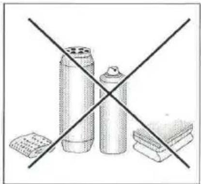
- Do not use plastic containers and aluminium foil. They melt at high temperatures and may damage the cooking surface.
- Solid or liquid sugar, citric acid, salt or plastic must not be allowed to spill on the hot cooking zone.
- If sugar or plastic accidentally fall on the hot cooking zone, do not turn off the hob and scrape the sugar or plastic off with a sharp scraper. Protect hands from burns and injuries.
SAFETY INSTRUCTIONS FOR USE
- When cooking on induction hob only use pots and pans with a flat base having no sharp edges or burrs as these can permanently scratch the cooking surface.
- Induction hob cooking surface is resistant to thermal shock. It is not sensitive to cold nor hot.
- Avoid dropping objects on the cooking surface. In some circumstances, point impacts such as dropping a bottle of spices, may lead to cracks and chipping of the cooking surface.
- If any damage occurs, seething food can get into the live parts of the induction hob through damaged areas.
- If the cooking surface is cracked, switch off power to avoid the risk of electric shock.
- Do not use the cooking surface as a cutting board or work table.
- Do not place metal objects such as knives, forks, spoons, lids and aluminium foil on the cooking surface as they could become hot.
- Do not install the hob over a heater without a fan, over a dishwasher, refrigerator, freezer or washing machine.
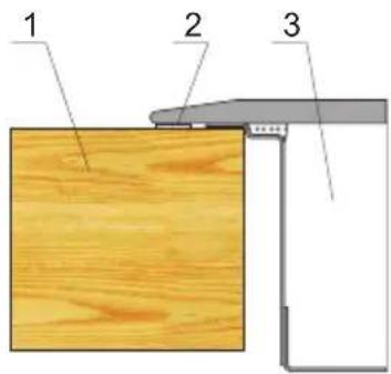
- If the hob has been built in the kitchen worktop, metal objects located in a cabinet below can be heated to high temperatures through the air flowing from the hob ventilation system. As a result it is recommended to use a partition (see Figure 2).
- Please follow the instructions for care and cleaning of induction hob. In the event of misuse or mishandling warranty may be void.
HOW TO SAVE ELECTRICITY

natural_image
Simple line drawing of a tree with cloud-like canopy and two wavy lines at base (no text or symbols)Using the electricity in a responsible manner not only saves money, but also helps protect the environment. So let's save electricity! This is how it's done:
- Use the correct cookware.
Cookware with flat and a thick base can save up to 1/3 of electricity. Please remember to cover cookware with the lid, otherwise electricity consumption increased four times!
●Always keep the cooking zones and cookware bases clean.
Dirt prevents proper heat transfer. Often burnt stains can be removed only with agents harmful to the environment.
- Avoiding unnecessary lifting the lid to peek into the pot.
- Do not install the hob in the immediate vicinity of refrigerator / freezer.
The electricity consumption is then unnecessarily increased.
UNPACKING

natural_image
Simple line drawing of a three chasing recycling symbol (no text or labels)The appliance was protected from damage at the time of transport. After unpacking, please dispose of all elements of packaging in a way that will not cause damage
to the environment. All materials used for packaging the appliance are environmentally friendly; they are 100% recyclable and are marked with the appropriate symbol.
Important! Keep the packaging material (bags, Styrofoam pieces, etc.) out of reach of children during unpacking.
DISPOSAL
In accordance with European Directive 2012/19/UE and Polish legislation regarding used electrical and electronic goods, this appliance is marked with the symbol of the crossed-out waste container.
This marking means that the appliance must not be disposed of together with other household waste after it has been used. The user is obliged to hand it over to waste collection centre collecting used electrical
and electronic goods. The collectors, including local collection points, shops and local authority departments provide recycling schemes. Proper handling of used electrical and electronic goods helps avoid environmental and health hazards resulting from the presence of dangerous components and the inappropriate storage and processing of such goods.

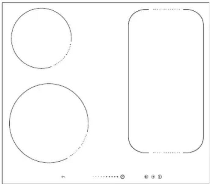
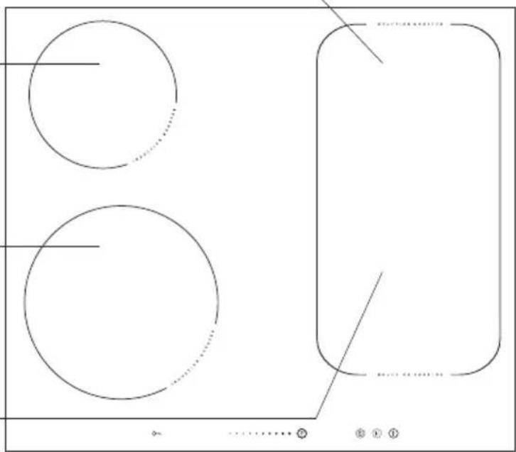
Description of hob
Induction cooking zone booster ∅ 180 mm (rear right)
Induction cooking zone booster ∅ 160-180 mm (rear left)
Induction cooking zone booster ∅ 210-220 mm (front left)
Induction cooking zone booster ∅ 180 mm (front right)
natural_image
Pure geometric diagram with circles and rectangles, no text or symbols present
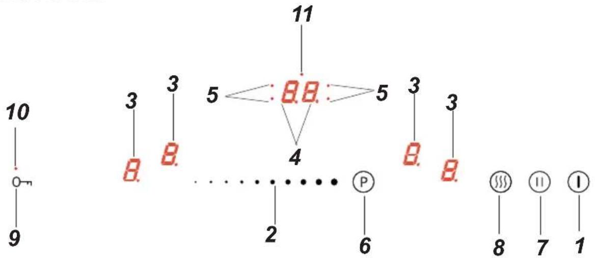
Control Panel
flowchart
graph TD
    A["10"] --> B["O"]
    B --> C["9"]
    D["3"] --> E["B."]
    F["3"] --> G["B."]
    H["5"] --> I["8.B."]
    I --> J["4"]
    K["5"] --> L["3"]
    M["3"] --> N["B."]
    O["3"] --> P["B."]
    Q["2"] --> R["P"]
    S["6"] --> T["8"]
    U["11"] --> V["7"]
    W["I"] --> X["1"]
- On/off sensor field
- Heat setting selection sensor field
- Cooking zone indicator
- Timer display
- Timer indicator light
- Booster sensor field
- Stop'n go function sensor field
- Keep Warm function sensor field
- Child lock sensor
- Child lock indicator light
- Kitchen timer indicator light
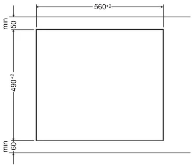
Making the worktop recess.
- Worktop thickness should be 28 - 40 mm, while its width at least 600 mm. The worktop must be flat and level. Edge of the worktop near the wall must be sealed to prevent ingress of water or other liquids.
- There should be sufficient spacing around the opening, in particular, at least 50 mm distance to the wall and 60 mm distance to the front edge of worktop.
- The distance between the edge of the opening and the side wall of the furniture should be minimum 55 mm.
- Worktop must be made of materials, including veneer and adhesives, resistant to a temperature of 100°C. Otherwise, veneer could come off or surface of the worktop become deformed.
- Edge of the opening should be sealed with suitable materials to prevent ingress of water.
● Worktop opening must cut to dimensions as shown on figure 1. - Ensure minimum clearance of 25 mm below the hob to allow proper air circulation and prevent overheating. See Figure 2.
1
text_image
560⁺² 50 490⁺² 60 min minFig.2
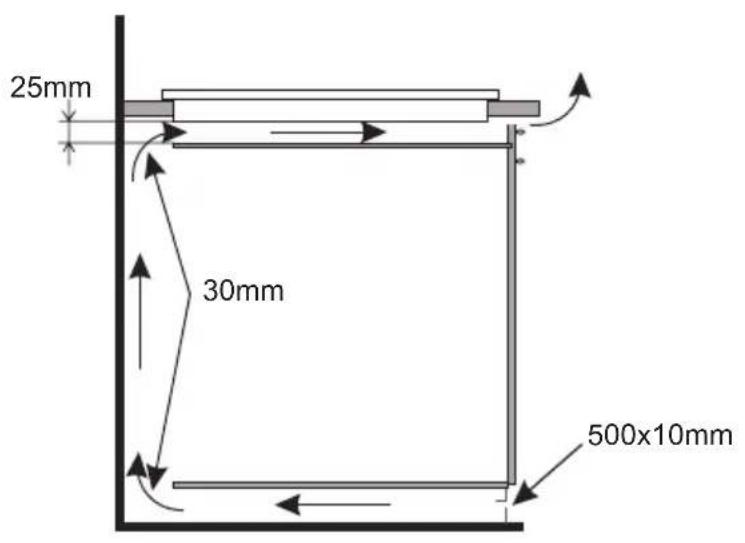
text_image
25mm 30mm 500x10mm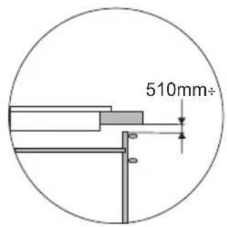
text_image
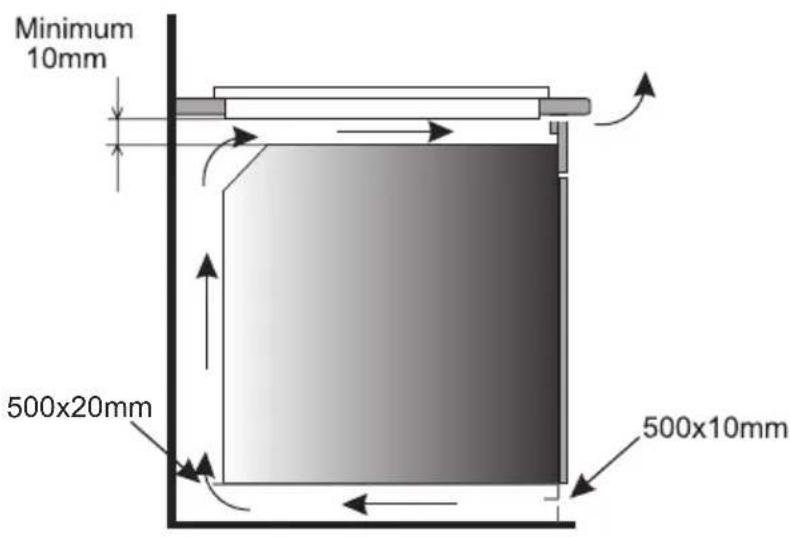
510mm÷Installing hob in kitchen cabinet worktop.
text_image
Minimum 10mm 500x20mm 500x10mm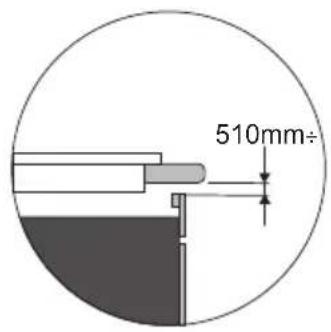
text_image
510mm÷Installing hob in kitchen worktop above oven with ventilation.

Do not install the hob above the oven without ventilation.
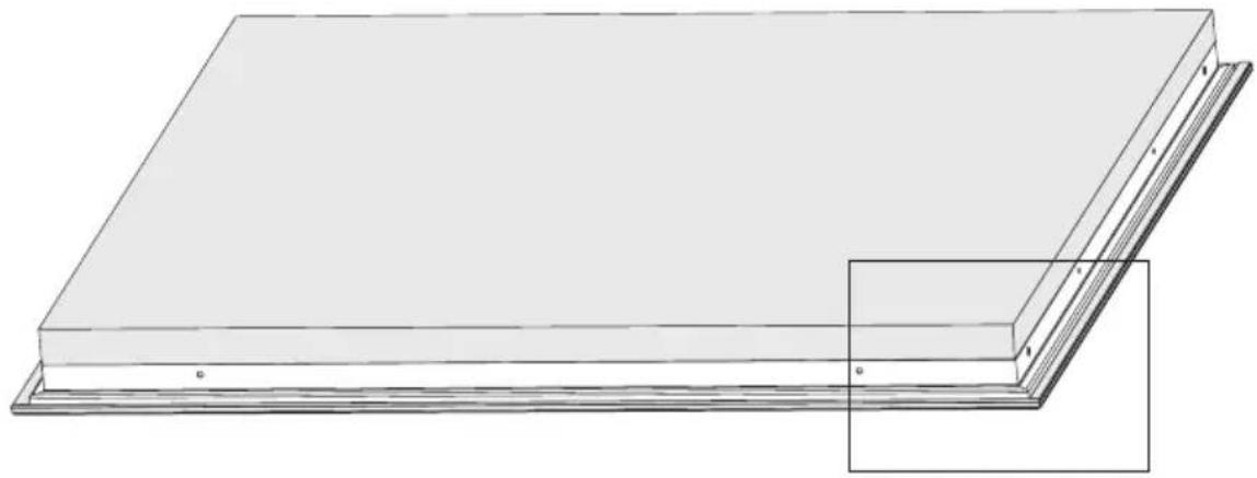
Installation of self-adhesive foam gasket *
Do not install the appliance without the foam gasket.
The gasket must be applied on the appliance as follows:
Before fitting the appliance in the kitchen worktop, apply self-adhesive foam gasket provided underneath the rim.
- before applying, remove the protective film from the self-adhesive foam gasket
- apply the self-adhesive foam gasket underneath the appliance rim (Figure)
natural_image
3D diagram of a rectangular panel with a flanged edge and a small inset showing a section (no text or symbols)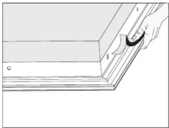
natural_image
Line drawing of a hand holding a paper clip attached to a wooden plank (no text or symbols)* some models come with the sealing glued to the board

Installing hob
- Using an electrical cord, connect the hob according to electrical diagram provided.
- Remove dust from the worktop, insert hob into the opening and press in firmly (Figure 3).
Fig. 3
text_image
1 2 31 - Worktop
2 - Hob flange gasket
3 - Ceramic hob
Connecting to electrical mains
Important!
Electrical connection must be made by a properly certified qualified installer. Do not make any alterations in the appliance electrical system.
Tips for the installer
The hob is equipped with a terminal block allowing different connections appropriate for a specific type of power supply.
Terminal block allows the following connections:
- single-phase 230 V \~
- two-phase 400 V 2N \~
- three-phase 400 V 3N \~
The hob can be adapted to a specific type of power supply by bridging the appropriate terminals according to wiring diagram. Wiring diagram is placed on the hob's underside. The terminal block can be accessed by removing the lid on hob's underside. Remember to match the power cord to the type of connection and the hob's power rating.
Important!
Remember to connect the neutral lead to correct terminal block clamp, marked with ⏻. The electrical system supplying the hob must be protected by a properly selected tripping device or a circuit breaker allowing to disconnect the power supply in an emergency.
Before connecting the appliance to power, please carefully read the information provided on the rating plate and wiring diagram.
Connecting the hob other than shown on the wiring diagram may damage the hob.
CAUTION! The installer is obliged to provide the user with "appliance electrical connection certificate" (enclosed with the warranty card). After installation, the installer should also provide information on the connection made:
- single-phase, two-phase or three-phase,
- conductor cross-section,
- electrical protection (fuse type).
| WIRING DIAGRAMImportant! Heating elements operate at 230V. | |||||
| Important! For each connection the protective conductor must be connected to the terminal marked [IMAGE]. | Type /Conductorcross section | Fuse protection | |||
| 1 | For a 230 V single phase connection with a neutral lead, terminals L1, L2 are bridged, neutral lead is connected to terminal N, and the protective conductor to [IMAGE] | 1N~ | 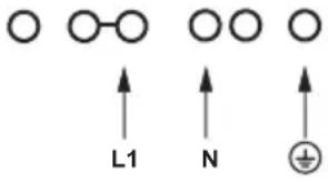 | HO5VV-FG 3 × 4 mm^2 | min.30 A |
| 2* | For a 230/400 V two phase connection with a neutral lead, neutral lead is connected to terminal N, and the protective conductor to [IMAGE]. | 2N~ | 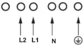 | HO5VV-FG 4 × 2,5 mm^2 | min.16 A |
| 3* | For a 230/400 V three phase connection with a neutral lead, neutral lead is connected to terminal N, and the protective conductor to [IMAGE]. | 3N~ | 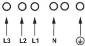 | HO5VV-FG 5 × 1,5 mm^2 | min.16 A |
| L1=R, L2=S, L3=T; N = neutral lead connection; [IMAGE] = protective lead terminal | |||||
* For domestic 3-phase 230/400 V electrical system, connect the remaining wire to the terminal:L3, which is not connected to the hob internal electrical system.
* NN terminals are internally connected, they need not be bridged
Before using the appliance for the first time
- thoroughly clean your induction hob first. The induction hob should be treated with the same care as a glass surface.
- switch on the ventilation in the room or open a window, as the appliance could emit an unpleasant smell during first use.
- operate the appliance while observing all safety guidelines.
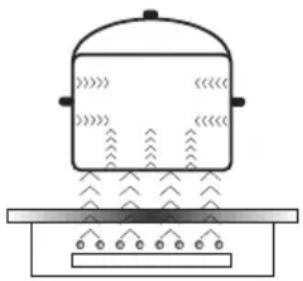
Induction cooking zone operation principle
natural_image
Simple line drawing of a steam locomotive with tracks and wheels (no text or symbols)Electric oscillator powers a coil placed inside the appliance. This coil produces a magnetic field, which induces eddy currents in the cookware.
These eddy currents induced by the magnetic field cause the cookware to heat up.
This requires the use of pots and pans whose base is ferromagnetic, in other words susceptible to magnetic fields.
Overall, induction technology is characterized by two advantages:
- the heat is only emitted by the cookware and its use is maximised,
- there is no thermal inertia, since the cooking starts immediately when the pot is placed on the hob and ends once it is removed.
Certain sounds can be heard during normal use of the induction hob, which do not affect its correct operation.
- Low-frequency humming. This noise arises when the cookware is empty and stops when water is poured or food is placed in the cookware.
- High-frequency whizz. This noise arises in cookware made of multiple layers of different materials at maximum heat setting. The noise intensifies when using two or more cooking zones at maximum heat setting. The noise will stop or reduce when heat setting is reduced.
- Creaking noise. This noise arises in cookware made of multiple layers of different materials. The noise intensity depends on how the food is cooked.
- Buzzing. Buzzing can be heard when electronics cooling fan operates.
The noises that can be heard during the normal appliance operation are the result of the cooling fan operation, cooking method, cookware dimensions, cookware material and the heat setting. These noises are normal and do not indicate a fault.
The protective device:
If the hob has been installed correctly and is used properly, any protective devices are rarely required.
Fan: protects and cools controls and power components. It can operate at two different speeds and is activated automatically. Fan runs until the electronic system has sufficiently cooled down regardless of the appliance or the cooking zones being turned on or off.
Temperature sensor: Temperature of electronic circuits is continuously monitored by a temperature sensor. If temperature is raised beyond a safe level, this protection system will reduce cooking zone heat setting or shut down the cooking zones adjacent to the overheated electronic circuits.
Pan detection: allows the hob to detect pans placed on a cooking zone. Small objects placed on the cooking zone (eg, spoon, knife, ring ...) will not be recognised as pans and the hob will not operate.
Pan detector
Pan detector is installed in induction hobs. Pan detector starts heating automatically when a pan is detected on a cooking zone and stops heating when it is removed. This helps save electricity.
- When an suitable pan is placed on a cooking zone, the display shows the heat setting.
- Induction requires the use of suitable cookware with ferromagnetic base (see Table page 18).
If a pan is not placed on a cooking zone or the pan is unsuitable, the symbol is displayed. The cooking zone will not operate. If a pan is not detected within 90 seconds, the cooking zone will be switched off.
Switch off the cooking zone using the touch control sensor field rather than by removing the pan.

Pan detector does not operate as the on/off sensor.
The induction hob is equipped with electronic touch control sensor fields, which are operated by touching the marked area with a finger.
Each time a sensor field is touched, an acoustic signal can be heard.
When switching the appliance on or off or changing the heat setting, attention should be paid that only one sensor field at a time is touched. When two or more sensor fields are touched at the same time (except timer and child lock), the appliance ignores the control signals and may trigger a fault indication if sensor fields are touched for a long time.
When you finish cooking switch off the cooking zone using touch control sensor fields and do not rely solely on the pan detector.
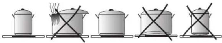
The high-quality cookware is an essential condition for efficient induction cooking.

Select cookware for induction cooking
natural_image
Six identical cooking pots with crossed X marks, arranged horizontally (no text or symbols)Cookware characteristics.
- Always use high quality cookware, with perfectly flat base. This prevents the formation of local hot spots, where food might stick. Pots and pans with thick steel walls provide superior heat distribution.
- Make sure that cookware base is dry: when filling a pot or when using a pot taken out of the refrigerator make sure its base is completely dry before placing it on the cooking zone. This is to avoid soiling the surface of the hob.
- Lid prevents heat from escaping and thus reduces heating time and lowers energy consumption.
- To determine if cookware is suitable, make sure that its base attracts a magnet.
- Cookware base has to be flat for optimal temperature control by the induction module.
- The concave base or deep embossed logo of the manufacturer interfere with the temperature induction control module and can cause overheating of the pot or pan.
- Do not use damaged cookware such as cookware with deformed base due to excessive heat.
- When you use large ferromagnetic base cookware, whose diameter is less than the total diameter of the cookware, only the ferromagnetic base heats up. This results in a situ-
ation where it is not possible to uniformly distribute the heat in the cookware. If the ferromagnetic area is reduced due to inclusion of aluminium parts then the effective heated area can be reduced. Problems with the detection of the cookware could arise or cookware may not be detected at all. To achieve optimum cooking results, the diameter of the ferromagnetic base should match that of the cooking zone. If cookware is not detected in a given cooking zone, it is advisable to try it in a smaller cooking zone.
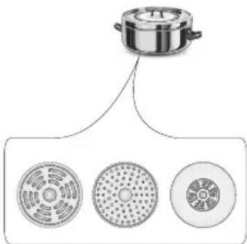
text_image
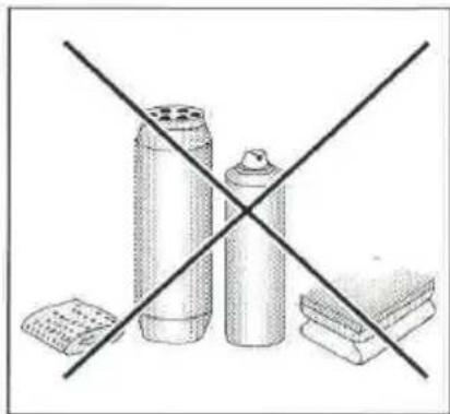
Diagram showing a cooking pot with three circular kitchenware items below, likely illustrating a cooking or processing setup.For induction cooking us only ferromagnetic base materials such as:
- enamelled steel
- cast iron
- special stainless steel cookware designed for induction cooking.
| Marking of kitchen cookware | 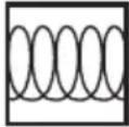 | Check for marking indicating that the cookware is suitable for induction cooking. |
| Use magnetic cookware (enamelled steel, ferrite stainless steel, cast iron). The easiest way to determine if your cookware is suitable is to perform the „magnet test”. Find a generic magnet and check if it sticks to the base of the cookware. | ||
| Stainless Steel Cookware | is not detected | |
| With the exception of the ferromagnetic steel cookware | ||
| Aluminium Cookware is not detected | ||
| Cast iron High efficiency | ||
| Caution: cookware can scratch the hob surface | ||
| Enamelled steel High efficiency | ||
| Cookware with a flat, thick and smooth base is recommended | ||
| Glass Cookware is not detected | ||
| Porcelain Cookware is not detected | ||
| Cookware with copper base | Cookware is not detected | |
The smallest useful diameter of cookware for a cooking zone:
| Cooking zone diameter | The minimum diameter of the bottom of an enamelled steel cookware |
| [mm] [mm] | |
| 160 - 180 | 110 |
| 180 - 200 | |
| 210 - 220 | 125220 x 190 |
| 260 - 280 |
The minimum diameter of cookware made of materials other than enamelled steel may vary.

Control Panel
- Immediately after the appliance is connected to electrical mains, all displays will light up briefly. Your induction hob is then ready for use.
- The induction hob is equipped with electronic touch control sensor fields, which are operated by touching with a finger for at least 1 second.
- Touching of a sensor field is accompanied by an acoustic signal to acknowledge.

No objects should be placed on the sensor fields (this could cause an error). Touch sensor fields should be always kept clean.
Switch on the appliance
To switch on the appliance touch and hold the on/off sensor field (1) for at least 1 second. The appliance is switched on when all heat setting displays (3) show "0".

If none of the sensor fields is touched within 10 seconds, the appliance switches itself off.
Switch on the cooking zone
Once the appliance is switched on using the on/off touch sensor (1), select a cooking zone (3) within the next 10 seconds.
-
When a cooking zone selection sensor field (3) is touched, "0" on the corresponding heat setting indicator display will pulsate.
-
To select the desired heat setting, slide your finger across the setting selection sensor field (2).

If none of the sensor fields is touched within 10 seconds of switching on the appliance, the cooking zone switches off.

A cooking zone is active when its display shows a digit or a letter. This indicates the cooking zone is ready for the heat setting to be set or changed.
Selecting the cooking zone heat setting
When the cooking zone display (3) shows pulsating "0" start setting the desired heat setting by sliding your finger across the setting selection sensor field (2).
Deactivate cooking zones
- A given cooking zone must be active. Heat setting display pulsates.
- To switch off a cooking zone touch the on/off sensor field or touch the sensor (3) for 3 seconds. Slide your finger across the heat selection sensor field (2) to reduce the heat setting to "0"
Switch off the appliance
- The appliance operates when at least one cooking zone is on.
- To switch off the appliance touch the on/off sensor (1).
If a cooking zone is still hot, the relevant display (3) will show the letter "H" to indicate residual heat.
Booster function "P"
The Booster Function increases the nominal power of the:
∅ 180 - from 1600W to 2500W
∅ 210-220 - from 2000W to 3000W
∅ 160-180 - from 1200W to 1400W
Bridge from 3000W to 5000W.
In order to activate the Booster function, select the cooking zone and then using sensor (6) set the heat setting to "P". The letter "P" will be shown on the display (3).
To switch off the Booster function, touch the heat setting selection sensor field (2) and reduce the heat setting, or lift the pot from the cooking zone.

For ∅ 180, ∅ 210-220, ∅ 160-180 cooking zone, operation of the Booster function is limited to 10 minutes. Once the Booster function is automatically deactivated, the cooking zone continues to operate at its nominal power.
The Booster function can be reactivated, provided the appliance electronic circuits and induction coils are not overheated.
When the pot is lifted from the cooking zone when the Booster function is in operation, it remains active and the countdown continues.
When the appliance electronic circuits or induction coils overheat when the Booster function is in operation, it is automatically deactivated. The cooking zone continues to operate at its nominal power.
Booster function control

Depending on the model, the cooking zones are paired vertically or crosswise. Total power is shared within the paired cooking zones..
If you attempt to enable the Booster function for both cooking zones simultaneously, the maximum power available would be exceeded. In that case the heat setting of the first activated cooking zone will be reduced to the highest level available.
The child lock function
The Child Lock function protects the appliance from inadvertent operation by children. The appliance can be operated once the child lock function has been released.
The Child Lock function can be set when the appliance turned on or off.
Turn Child Lock on/off
Touch and hold sensor (9) for 5 seconds to turn Child Lock on/off. Indicator light (10) is on when the Child Lock function is on.

The Child Lock function remains set until it is released even after the appliance has been switched off and then switched on again. Disconnecting the appliance from electrical mains deactivates the Child Lock.
Residual heat indicator
Heat energy that remains accumulated in the cooking zone after cooking is called the residual heat. The appliance displays two different levels of residual heat. When a cooking zone temperature is above 60^ C and the cooking zone or the appliance is switched off, the relevant cooking zone display will show the letter "H". Residual heat indication is displayed as long as the cooking zone temperature exceeds 60^ C. When a cooking zone temperature is between 45^ C and 60^ C, the relevant cooking zone display will show the letter "h" indicating low residual heat. When a cooking zone temperature is below 45^ C the residual heat indication is turned off.

When residual heat indicator is on, do not touch the cooking zone as there is a risk of burns and do not place on it any items sensitive to heat!

The "H" residual heat indicator is not displayed during a power outage. However, cooking zones may still be hot!

Limit the operating time
In order to increase efficiency, the induction hob is fitted with a operating time limiter for each of the cooking zones. The maximum operating time is set according to the last heat setting selected.
If you do not change the heat setting for a long time (see table) then the associated cooking zone is automatically switched off and the residual heat indicator is activated. However, you can switch on and operate individual cooking zones at any time in accordance with the operating instructions.
| Cooking heat setting | Maximum operating time (hours) |
| - = ≡ | 8 |
| 1 | 8 |
| 2 | 8 |
| 3 | 5 |
| 4 | 5 |
| 5 | 5 |
| 6 1.5 | |
| 7 1.5 | |
| 8 1.5 | |
| 9 1.5 | |
| P 0.16 |
Automatic warm-up function
- Touch sensor field (3) to activate the selected cooking zone.
- Then sliding your finger across the setting selection sensor field (2) set the desired heat setting in the 1-8 range and then touch sensor field (3) again.
- The display will alternate between the letter A and the heat setting.
After a certain time of operation at boosted power, the cooking zone switches back to the heat setting set, which will be shown on the display.
| Cooking heat setting | The duration of the automatic warm-up (minutes) |
| - | |
| 1 0.8 | |
| 2 1.2 | |
| 3 2.3 | |
| 4 3.5 | |
| 5 4.4 | |
| 6 7.2 | |
| 7 | 2 |
| 8 3.2 |

If a pot is lifted from the cooking zone and replaced before the warm-up countdown is completed, the warm-up function will resume and countdown will continue until completed.
Timer
Timer function makes cooking easier by making it possible to set Duration. It can also be used as a Kitchen Timer.
Set the Timer
Timer function makes cooking easier by making it possible to set Duration. The timer function can only be set when a cooking zone is operating (heat setting is greater than "0"). The timer function can be set independently for all individual cooking zones. Timer countdown can be set from 1 to 99 minutes.
To set the timer:
- select a cooking zone by touching cooking zone selection sensor field (3) and select the desired heat setting from 1 to 9 by sliding your finger across the heat setting selection sensor field (2). The display will show the selected heat settings from 1 to 9.
- then, during the next 10 seconds, touch the Timer selection sensor field (4). "00" will be shown on the Timer display (4) and the appropriate Timer activation indicator light (5) will light up to indicate activation of the Timer function for the relevant cooking zone.
- Now, select the desired Timer setting by sliding your finger across the setting selection sensor field (2). The second digit is set first and the first digit is set next. Once the second digit is set, touch the sensor (4) again to set the first digit. If you do not set any value for the first digit within 10 seconds, the value will be set to "0"(eg."06").
The countdown starts when the Timer activation indicator light (5) starts flashing.

Timer countdown can be set independently for all cooking zones.

If more than one timer is set the shortest duration is displayed. Timer indicator light (5) of a relevant cooking zone will flash.
Change Timer Duration
Programmed Timer setting can be changed at any time.
To change the programmed Timer setting, select a cooking zone by touching the cooking zone selection sensor field (3), and then touch the Timer selection sensor field (4).
Check Timer Duration
To check progress of Timer countdown at any time, touch the timer sensor field (4). Timer indicator light (5) of a relevant cooking zone will flash.
Stop the Timer
When the set time has elapsed an acoustic signal is sounded, which can be muted by touching any sensor field. If no sensor field is touched, the acoustic signal will stop automatically after 2 minutes.
To stop the timer countdown before the set Duration has elapsed:
- Touch cooking zone selection sensor field (3) to select a cooking zone. The display will become bright.
- Then touch and hold sensor field (4) for 3 seconds or adjust duration using the sensor field (2) sliding your finger down to "00"
Kitchen Timer
When no cooking zones are in use, the Timer function can be used as a regular Kitchen Timer.
Set Kitchen Timer
When the appliance is off:
- Touch the on/off sensor (1) to turn on the appliance. "0" will be shown on cooking zone displays (3).
- then, during the next 10 seconds, touch the Kitchen timer selection sensor field (4). Kitchen timer display (4) will show "00."
- Now, select the desired Timer setting by sliding your finger across the setting selection sensor field (2). The second digit is set first and the first digit is set next. Once you set the second digit, the appliance will automatically allow you to set the first digit. If you do not set any value for the first digit within 10 seconds, the value will be set to "0"(eg."06"). The kitchen timer starts countdown when the indicator lamp (11) starts flashing.
Stop Kitchen Timer
When the set Duration has elapsed an acoustic intermittent signal is sounded (beeping), which can be muted by touching any sensor field. If no sensor field is touched, the acoustic signal will stop automatically after 2 minutes.
To stop the timer countdown before the set Duration has elapsed:
- Then touch and hold sensor field (4) for 3 seconds or adjust duration using the sensor field (2) sliding your finger down to "00"
- Kitchen Timer function does not affect cooking zone operation.

Kitchen timer is reset when the timer function is activated.
Keeping food warm
Keep warm function allows you to keeping food warm on a cooking zone. The selected cooking zone operates at a low heat setting. With this feature, ready to serve, warm food retains its taste and does not stick to the pot's bottom. This function can be used to melt butter or chocolate.
For the keep food warm function to operate correctly, use a flat base pot or frying pan, so that base temperature is accurately measured by the temperature sensor fitted in the cooking zone. The Keep Warm function can be activated for any cooking zone.
The different keep warm temperatures can be set for cooking zone, namely 42^ C, 70^ C or 94^ C.
To activate Keep Warm function:
- Touch sensor (3) to select the cooking zone, then touch Keep Warm function sensor field (8) and the display will show the — symbol indicating that temperature of 42^ C is selected,
- Touch Keep Warm function sensor field (8) again and the second = symbol will be shown indicating that temperature of 70^ C is selected,
- Touch Keep Warm function sensor field (8) again and the third ≡ symbol will be shown indicating that temperature of 94°C is selected,
- To turn off the Keep Warm function at any time touch sensor (3), and then slide across the sensor (2) to reduce heat setting to „0”.
Stop'n go function "||"
Stop'n go function acts like a pause. The Stop'n go function simultaneously suspends operation of all cooking zones and then resumes at the heat settings that were previously set.
In order to activate the Stop'n go function, at least one cooking zone must be in use.
Next, touch the Stop'n go function sensor field (7). "II" will be shown on all cooking zone displays (3). When a cooking zone is still hot, the "II" symbol will alternate between "H" and "h" indicating residual heat in a given cooking zone.
To deactivate the Stop'n go function touch the (7) sensor field again. Cooking zone displays (3) will show the heat setting that was previously set before activation of the Stop'n go function.
Bridge function
The Bridge function allows pairing of two cooking zones into a single combined cooking zone. The Bridge function is very convenient, especially when cooking in large pots such as a baking pan.
The two right cooking zones can be bridged.
In order to activate the Bridge function touch sensor of the cooking zone (3) and then simultaneously touch two sensors of the cooking zone (3) on the left or right side. The rear cooking zone display will show "☐", while the front cooking zone display will show "0". The desired heat setting is selected by sliding your finger across the setting selection sensor field (2).

Now both cooking zones can be controlled at the same time.
In order to deactivate the Bridge function touch and hold sensor of the cooking zone (3) with symbol „☐” for 3 seconds. The respective cooking zone displays will show "0".

Now both cooking zones can be controlled independently.
Proper routine maintenance and cleaning of the appliance can significantly extend its trouble-free operation.

When cleaning induction hobs, the same principles apply as for glass surfaces. Do not use under any circumstances any abrasive or caustic cleaners or scouring powders or pads! Do not use steam or pressure cleaners.
natural_image
Crossed construction diagram showing construction materials and a concrete block (no text or symbols)Cleaning after each use
- Wipe light stains with a damp cloth without detergent. The use of dishwashing liquid may cause a bluish surface discolouration. These persistent stains cannot always be removed right away, even using a special cleaner.
- Firmly adhering dirt can be carefully removed with a scraper. Then wipe the cooking surface with a damp cloth.
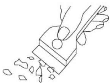
natural_image
Line drawing of a hand using a tool to cut or spread material, with no text or symbols present.Scraper to clean the hob
Removing stains
- Bright stains of pearl colour (residual aluminium) can be removed from the cool hob using a special cleaning agent. Limestone residue (eg. after evaporated water) can be removed by vinegar or a special cleaning agent.
- Do not turn off the cooking zone when removing sugar, food containing sugar, plastic and aluminium foil. Immediately and thoroughly scrape the leftovers off the hot cooking zone using a sharp scraper. Once the bulk of the stain is removed the hob can be turned off and clean the cooled off cooking zone with a special cleaning agent.
Do not use any descaling agents to clean the hob.
Special cleaners are available in supermarkets, electrical and home appliance shops, drug stores, as well as retail food shops and kitchen showrooms. Scrapers can be purchased in DIY and construction equipment stores, as well as in shops carrying painting accessories.
Never apply a detergent on the hot cooking zone. It is best to let the cleaner dry and then wipe it wet. Any traces of the detergent should be wiped off clean with a damp cloth before re-heating. Otherwise, it can be corrosive.
Warranty will be void if you do not follow the above guidelines!

Periodic inspections
In addition to normal cleaning and maintenance:
- carry out periodic checks of touch controls and other elements. After the warranty expires, have authorised service inspect the appliance every two years,
- repair and identified problems,
- carry out periodic maintenance of the hob.
Important!
If the hob's controls do not respond for whatever reason, then turn off the main circuit breaker or remove the fuse and contact customer service.
Important!
In the event of breakage or chipping of the hob cooking surface, turn off and unplug the appliance. To do this, disconnect the fuse or unplug the appliance. Then refer the repair to professional service.
Important!
All repairs and adjustments must be performed by a competent technician or by an authorised installer.
In the event of any fault:
- turn off the appliance
- disconnect the power supply
• have the appliance repaired
- Based on the instructions given in the table below, some minor issues can be corrected by the user. Please check the consecutive points in the table before you refer the repair to customer service.
| PROBLEM POSSIBLE CAUSE REMEDY | ||
| 1.The appliance does not work | - no power -check the fuse, | replace if blown |
| 2.Sensor fields do not respond when touched | - appliance is not turned on - | turn on the appliance |
| - sensor field touched too briefly (less than one second) | - touch the sensor field longer | |
| - multiple sensors touched at the same time | - always touch only one sensor field (except when a cooking zone is switched off) | |
| 3.The appliance does not respond and emits and extended beep | - improper use (wrong sensor fields touched or sensors touched too briefly) | - reconnect the hob |
| - sensor fields covered or dirty | - uncover or clean the sensor fields | |
| 4.The appliance switches itself off | - no sensor field is touched for 10 seconds of activating the appliance | - switch on the appliance and set heat setting without delay |
| - sensor fields covered or dirty | - uncover or clean the sensor fields | |
| 5.A single cooking zone switches off and residual heat indicator „H” is shown. | - limited cook time - switch on the cooking zone again | |
| - sensor fields covered or dirty | - uncover or clean the sensor fields | |
| - electronic components overheated | ||
| 6.Residual heat indicator extinguished even though the cooking zones are hot | - a power outage or the appliance has been disconnected | - residual heat indicator will be shown again the next time the appliance is turned on and off again |
| 7.Hob cooking surface is cracked. | Danger! Immediately unplug the appliance or switch off the main circuit breaker. Refer the repair to the nearest service centre. | |
| 8.When the problem is still not remedied. | Immediately unplug the appliance or switch off the main circuit breaker (fuse). Refer the repair to the nearest service centre. Important!You are responsible for operating the appliance correctly and maintaining its good condition. If you call service as a result of operating the appliance incorrectly you will be responsible for the costs incurred even under warranty.The manufacturer shall not be held liable for damage caused by failure to follow this manual. | |
| 9.Induction hob makes buzzing sound. | This is normal. Cooling fan is operating to cool down internal electronics. | |
| 10. Induction hob makes hissing and whistling sounds. | This is normal. When using several cooking zones at full power, the hob makes hissing and whistling sounds due to the frequencies used to power the coils. | |
| 11. The hob does not work. The cooking zones will not operate. | - faulty electronics - reset the | appliance,unplug it for a 60 seconds (disconnect the fuse). |
Rated voltage 230/400V 3N\~50 Hz
Rated power:
7,4 kW
Model:
PG4VI525FTB4SC / (BOXI*)
- induction cooking zone :
- induction cooking zone: ∅ 180 mm 1600 W
- induction cooking zone: ∅ 210-220 mm 2000 W
- induction cooking zone: ∅ 160-180 mm 1200 W
- booster induction cooking zone: ∅ 180 mm 1600/2500 W
- booster induction cooking zone: ∅ 210-220 mm 2000/3000 W
- booster induction cooking zone: ∅ 160-180 mm 1200/1400 W
Dimensions 576 x 518 x 59
Weight ca.10,5 kg;
;
Meets the requirements of European standards EN 60335-1; EN 60335-2-6.
natural_image
Simple line drawing of a tree with two roots and wavy lines at the base (no text or symbols)natural_image
Simple line drawing of a recycling symbol (three chasing arrows) with no text or labelstext_image
25mm 30mm 500x10mm
text_image
510mm÷text_image
Minimum 10mm 500x20mm 500x10mm
text_image
510mm÷natural_image
3D diagram of a rectangular panel with a flanged edge and a small inset showing a section (no text or symbols)
natural_image
Line drawing of a hand holding a paper clip attached to a wooden bracket (no text or symbols)natural_image
Simple line drawing of a cooking pot on a tray with no text or symbolsnatural_image
Illustration of five cooking pots with crossed-out x-marks, no text or symbols presentnatural_image
Diagram showing a cooking pot above three circular kitchen utensils (no text or labels)natural_image
Line drawing of a hand using a tool to cut or spread material from a block (no text or symbols)natural_image
Crossed construction diagram showing construction materials and a concrete block (no text or symbols)Vlekken verwijderen
Model: PG4VI525FTB4SC / (BOXI*)
- inductiekookzone:
natural_image
Line drawing of a standard open oven with control panel and door (no text or symbols)12223.3eEHpTsDpHbScX / BOXC 954 000 E
12223.3eEHpTsDpHbScX / BOXI 955 000 E
12223.3eEHpTsDpHbScSm / BOXC 954 000 SM
12223.3eEHpTsDpHbScSm / BOXI 955 000 SM
(HR) UPUTE ZA UPORABU....2
(SL) NAVODILO ZA UPORABO....32
ŠTOVANI KLIJENTI,
natural_image
Simple black-and-white line drawing of a tree with cloud-like canopy and two wavy lines at base (no text or symbols)natural_image
Simple line drawing of a recycling symbol (three chasing arrows), no text or labels present.Uređaj je za vrijeme transporta zaštićen od oštećenja. Nakon vađenja uređaja iz pakiranja molimo Vas da elemente ambalaže uklonite na način koji ne ugrožava okoliš. Svi materijali korišteni za pakiranje nisu štetni za okoliš, 100% materijala je prikladno za recikliranje, stoga su označeni odgovarajućim simbolom.
Pozor! Elemente pakiranja (polietilenske vrećice, komadići stiropora itd.) prilikom uklanjanja ambalaže držati daleko od djece.
Ovaj uređaj je označen u skladu s europskom uredbom 2012/19/EU i poljskim zakonom o potrošenom električnom i elektroničkom otpadu. Ujedno je označen simbolom prekriženog spremnika za otpatke.
natural_image
Isometric line drawing of a square frame with rounded corners and a small circular cutout at the top (no text or symbols)Pekač za pecivo*
natural_image
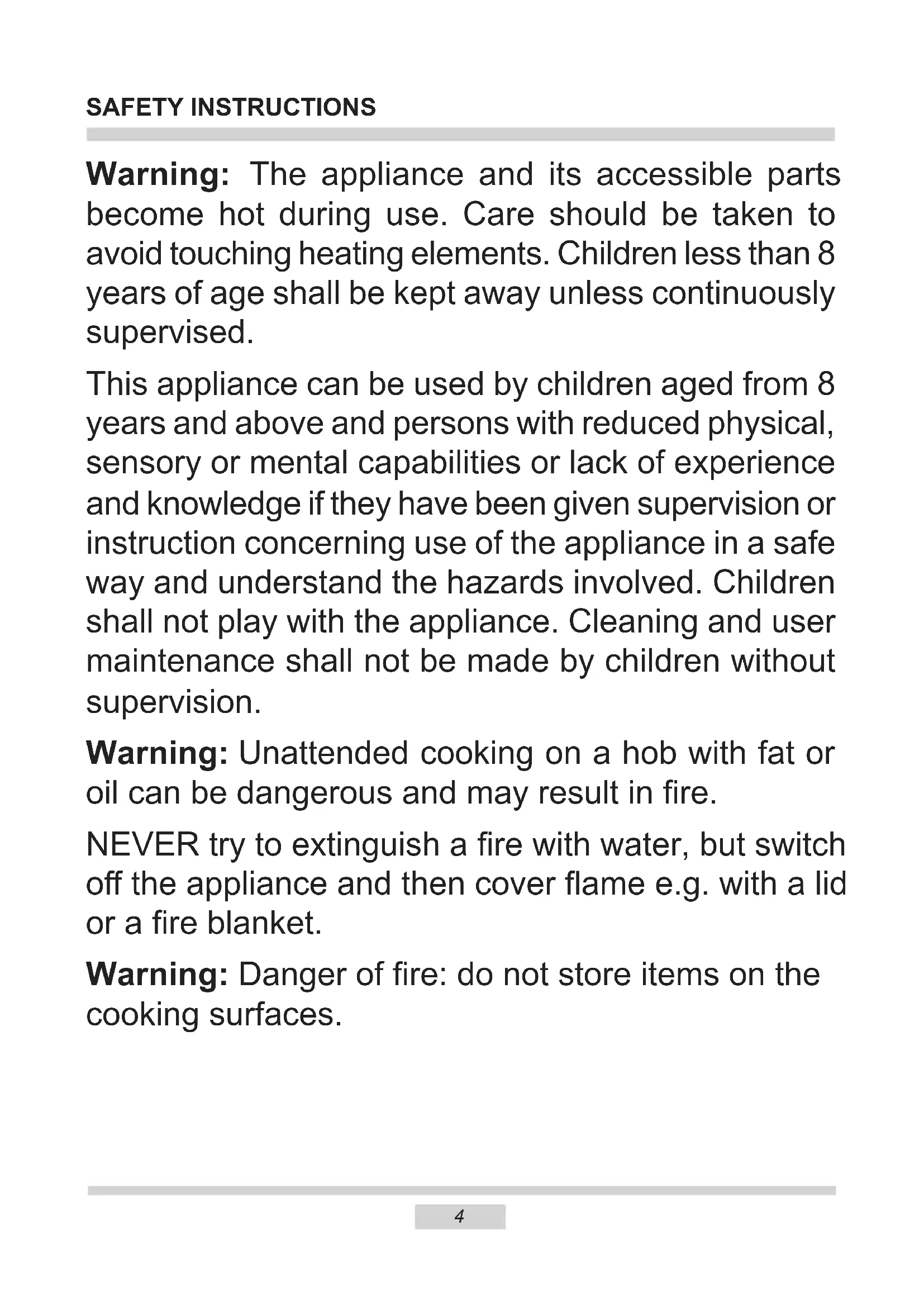
Technical line drawing of a rectangular metal grate or rack structure (no text or symbols)Ražanj za gril (rešetka sa štitnikom)
natural_image
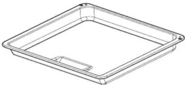
Line drawing of a rectangular tray with a recessed slot (no text or symbols)Plitica za pečenje*
natural_image
Top-down schematic of a rectangular device with internal grid pattern and directional arrows (no text or symbols)Pozor:
Montažu obavljamo kad je isključeno električno napajanje.
Priključivanje pećnice na električnu mrežu
Prije priključivanja pećnice na električnu instalaciju upoznati se s informacijama na natpisnoj pločici.
- Pećnica je tvornički prilagođena za jednofaznu izmjeničnu struju (230V 1N\~50 Hz) i opremljena priključnim kabelom 3 x 1,5 mm² dužine oko 1,5 m s utikačem sa zaštitnim kontaktom.
- Priključna utičnica mora biti opremljena zaštitnim kontaktom. Nakon postavljanja pećnice korisnici moraju imati slobodan pristup priključnoj utičnici.
- Prije priključivanja pećnice u utičnicu provjeriti da:
-osigurač i električna instalacija izdržavaju opterećenje štednjaka, električni krug koji napaja utičnicu trebao bi biti zaštićen osiguračem min. 16A, - električna instalacija je opremljena učinkovitim sustavom uzemljenja koji ispunjava uvjete trenutnih normi i propisa,
Nakon instalacije pećnice korisnici moraju imati slobodan pristup utikaču.
natural_image
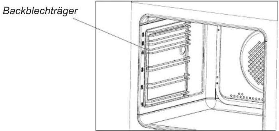
Diagram of a cylindrical device with a rotating arrow and base plate, no text or symbols presentVažno!
Elektronički programator Ts je opremljen senzorima koji djeluju kad prstom dodirujemo označene površine. Svako podešavanje senzora potvrđeno je zvučnim signalom. Površine senzora moraju biti čiste.
Elektronički programator\*
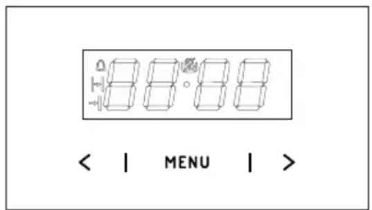
text_image
< | MENU | >text_image
Diagram illustrating the process of temperature change in a circular device, showing step-by-step rotation and adjustment.Isključivanje slijedi nakon podešavanja oba birača u položaju „●” / „0”.
Pozor!
natural_image
Technical diagram of a microwave oven with internal grid pattern and control knob (no text or symbols)Rasvjeta pećnice
natural_image
Technical diagram of a microwave oven with internal grid pattern and control knob (no text or symbols)Rasvjeta pećnice
Pozor! Paziti da montiranu halogenu žarulju neposredno ne dodirujemo prstima.
*Ovisno o modelu
ČIŠĆENJE I ODRŽAVANJE PEĆNICE
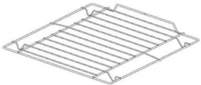
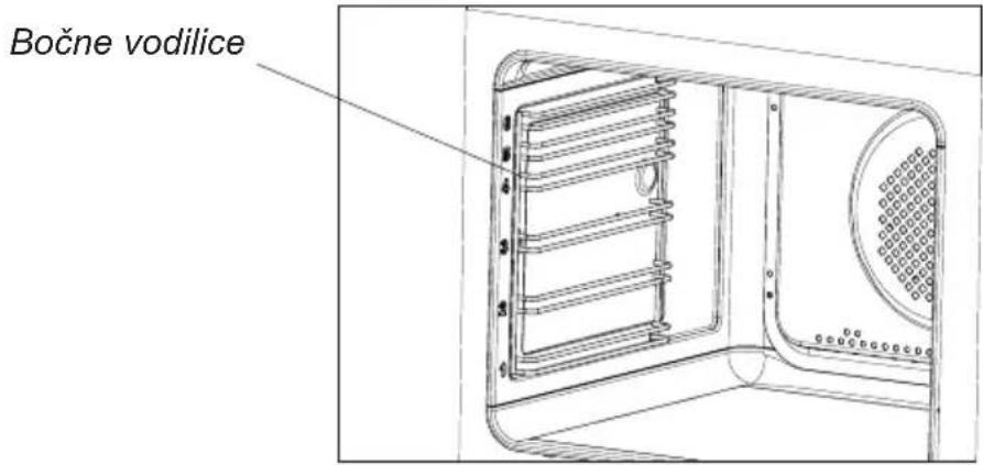
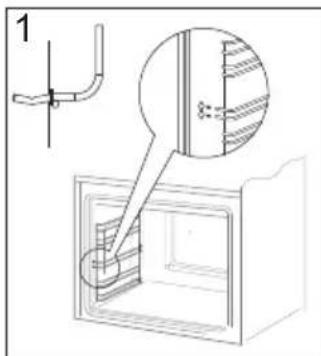
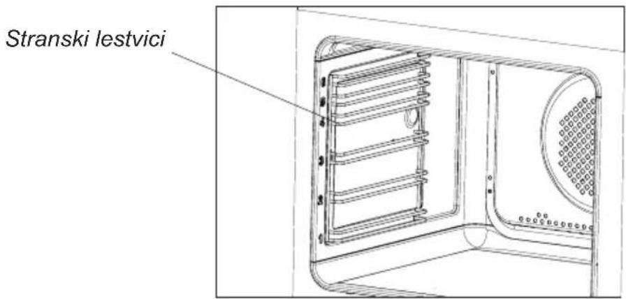
- Pećnice označene slovom D su opremljene lako izvlačivim žičanim vodilicama (rešetkama) za plitice pećnice. Vadimo ih tako da povučemo krajeve iz prednjih utora, nakon toga odvojimo vodilicu i izvadimo krajeve iz stražnjih utora.
text_image
1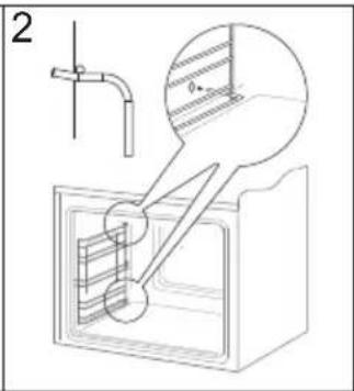
text_image
2Vađenje žičanih vodilica
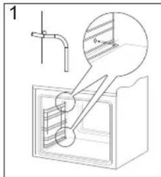
text_image
1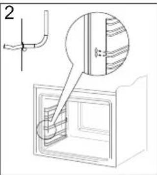
text_image
2Stavljanje žičanih vodilica
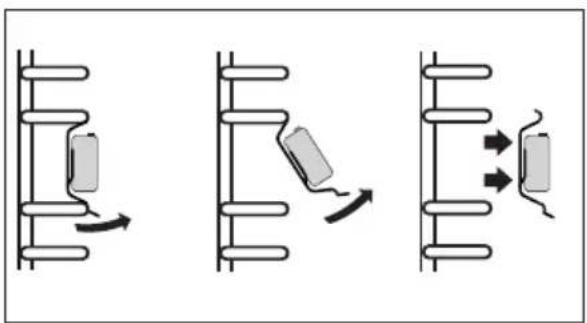
- Pećnice sa slovima Dp posjeduju nehrđajuće izvlačive vodilice plitica koje su pričvršćene na žičane vodilice. Vodilice izvlačiti i prati zajedno sa žičanim vodilicama. Prije postavljanja plitica, vodilice izvući (ako je pećnica zagrijana vodilice izvući tako da zakačimo stražnji rub plitice na odbojnike na prednjem dijelu izvlačivih vodilica) i nakon toga ugurati zajedno s pliticom.
Pozor!
Teleskopske vodilice ne prati u perili- cama za posuđe.
natural_image
Three diagrams showing mechanical or electrical components with directional arrows, no text or symbols present.natural_image
Diagram showing three sequential mechanical or electrical assembly steps with no visible text or symbolsnatural_image
Technical line drawing of a mechanical assembly with an inset showing a close-up of a component (no text or symbols present)Pomicanje zaštite šarki
natural_image
Technical line drawing of a mechanical assembly with a rectangular plate and a cylindrical component (no text or symbols)ČIŠĆENJE I ODRŽAVANJE ŠTEDNJAKA
- Unutrašnje staklo izvaditi iz ležišta (u do-njem dijelu vrata). Crt. D.
Pozor! Opasnost od oštećenja ležišta stakala. Staklo treba izvući, a ne podizati.
- Stakla oprati toplom vodom i malom količinom sredstva za čišćenje.
Za ponovnu ugradnju stakala postupite na isti način, ali obrnutim redom. Glatki dio stakla trebao bi se nalaziti gore, a srezani rubovi dolje.
natural_image
Simple black-and-white line drawing of a tree with two wavy lines at the base (no text or symbols)natural_image
Simple line drawing of a recycling symbol (three chasing arrows), no text or labels present.natural_image
Isometric line drawing of a square frame with rounded corners and mounting holes (no text or symbols)Pekač za pecivo*
natural_image
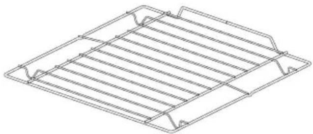
Technical line drawing of a rectangular metal grate or rack structure (no text or symbols)Rešetka za peko na žaru (sušilna lestvica)

natural_image
Line drawing of a rectangular tray with a recessed slot (no text or symbols)Pekač za peko (globoki)*
text_image
Stranski lestvici*Odvisno od modela
Vgradnja pečice
natural_image
Top-down schematic of a rectangular device with internal grid pattern and directional arrows (no text or symbols)Pozor:
Tekom izvajanja vgradnje naprava ne sme biti priklopljena na vir napajanja.
natural_image
Diagram of a cylindrical device with a rotating arrow and base, no text or symbols presentElektronski programmer\*

text_image
< | MENU | >MENU - senzor izbire načina delovanja
text_image
Diagram illustrating the process of temperature change in a circular device, showing step-by-step rotation and adjustment.Izklop se izvede z zasukom obeh gumbov vpoložaj „●” / „0”.
Pozor!
natural_image
Technical diagram of a microwave oven with a rotary knob and control knob (no text or symbols)Osvetlitev pečice
natural_image
Technical diagram of a microwave oven with internal grid pattern and control knob (no text or symbols)Osvetlitev pečice
natural_image
Three diagrams showing mechanical assembly steps with arrows indicating motion (no text or symbols)natural_image
Diagram showing three sequential mechanical or electrical assembly steps with no visible text or symbolsČIŠČENJE IN VZDRŽEVANJE ŠTEDILNIKA
Snemanje vrat
natural_image
Technical line drawing of a mechanical assembly with an inset magnified view of a component (no text or symbols)Odmik zaroval tečajev
natural_image
Technical line drawing of a mechanical assembly with a rectangular frame and a separate cylindrical component (no text or symbols)ČIŠČENJE IN VZDRŽEVANJE ŠTEDILNIKA
natural_image
Pure geometric shapes including circles and rounded rectangles without any text or symbolsPG4VI525FTB4SC / BOXI 955 000 E
(CZ) NÁVOD K OBSLUZE......2
(SK) NÁVOD NA OBSLUHU....33
natural_image
Simple line drawing of a tree with two roots and wavy lines at the base (no text or symbols)natural_image
Simple line drawing of a recycling symbol with three chasing arrows (no text or labels)text_image
25mm 30mm 500x10mm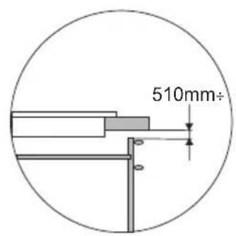
text_image
510mm÷text_image
Minimum 10mm 500x20mm 500x10mm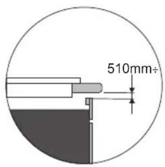
text_image
510mm÷natural_image
Technical line drawing of a layered rectangular panel or shelf with a small inset detail (no text or symbols)
natural_image
Line drawing of a hand holding a paper clip attached to a wooden bracket (no text or symbols)
Instalování desky
natural_image
Simple line drawing of a cooking pot on a tray with no text or symbolsnatural_image
Five identical cooking pots with crossed-out black X marks, arranged horizontally on a base (no text or symbols)Charakteristika nádob.
natural_image
Diagram showing a cooking pot connected to three circular components (no text or symbols)natural_image
Line drawing of a hand using a tool to cut or spread material, with no text or symbols present.natural_image
Diagram showing three containers crossed out by a diagonal line, no text or symbols presentOdstraňování skvrn
natural_image
Simple line drawing of a tree with cloud-like canopy and two wavy base lines (no text or symbols)natural_image
Simple line drawing of a three chasing recycling symbol (no text or labels)text_image
25mm 30mm 500x10mm
text_image
510mm÷text_image
Minimum 10mm 500x20mm 500x10mm
text_image
510mm÷natural_image
3D diagram of a layered rectangular panel or shelf with a small inset showing a separate section (no text or symbols)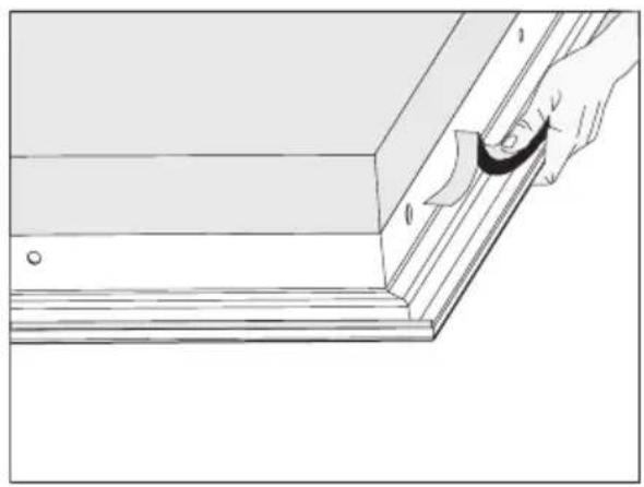
natural_image
Line drawing of a hand holding a paper clip attached to a wooden plank (no text or symbols)
Inštalovanie dosky
natural_image
Simple line drawing of a cooking pot with steam rising from a tray (no text or symbols)natural_image
Six identical cooking pots with crossed X marks, arranged horizontally on a base (no text or symbols)Charakteristika riadu.
natural_image
Line drawing of a hand using a tool to cut or spread material, with no text or symbols present.Čistiaca škrabka
natural_image
Diagram showing three cylindrical containers crossed out by a diagonal line, with no text or symbols present.Odstraňovanie škvín
Model: PG4VI525FTB4SC / (BOXI*)