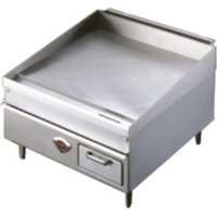
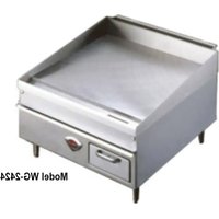
HDG3630G - Grill plate Wells - Free user manual and instructions
Find the device manual for free HDG3630G Wells in PDF.
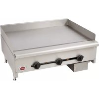
| Product type | Professional gas griddle |
| Brand | Wells |
| Model | HDG3630G |
| Category | Griddle |
| Number of burners | 3 (dual burners with individual control) |
| Fuel type | Natural gas or propane (LPG) |
| Manifold pressure (natural gas) | 5.0 in WC (12.7 cm H₂O) |
| Manifold pressure (propane) | 10 in WC (25.4 cm H₂O) |
| Total energy consumption | 90,000 BTU/h |
| Cooking surface material | Manufactured steel |
| Legs | 4 adjustable legs, height 10 cm (4 in) |
| Grease tray | 1 tray included |
| Ignition | Manual pilot |
| Usage | Commercial (establishments) |
| Standards | Compliant with ANSI Z83.11, NSF Standard 4, CSA |
| Cleaning | Daily with bristle brush, mild detergent |
| Safety | Leak detection with soapy water, emergency shut-off |
| Replacement parts (legs) | Ref. WS-20563 (set of 4) |
| Installation | Requires qualified and certified technician |
Frequently Asked Questions - HDG3630G Wells
User questions about HDG3630G Wells
0 question about this device. Answer the ones you know or ask your own.
Ask a new question about this device
Download the instructions for your Grill plate in PDF format for free! Find your manual HDG3630G - Wells and take your electronic device back in hand. On this page are published all the documents necessary for the use of your device. HDG3630G by Wells.
USER MANUAL HDG3630G Wells
Do not store gasoline or other flammable liquids
in the vicinity of this or any other appliance.
WARNING:
Improper installation, adjustment, alteration, service or maintenance can cause property damage, injury or death. Read the installation, operating and maintenance instructions thoroughly before installing or servicing this equipment.
IMPORTANT:
The purchaser of this equipment must post in a prominent location instructions to be followed in the event the user smells gas. This information shall be obtained by consulting the local gas supplier.

IMPORTANT: DO NOT DISCARD THIS MANUAL
This manual is considered to be part of the appliance and is to be given to the OWNER or MANAGER of the restaurant, or to the person responsible for TRAINING OPERATORS of this appliance. Additional manuals are available from your WELL'S DEALER.
THIS MANUAL MUST BE READ AND UNDERSTOOD BY ALL PERSONS USING OR
INSTALLING THIS APPLIANCE. Contact your WELLS DEALER if you have any
questions concerning installation, operation or maintenance of this equipment.
PRINTED IN CHINA
LIMITED WARRANTY STATEMENT
Unless otherwise specified, all commercial cooking equipment manufactured by Wells Manufacturing is warranted against defects in materials and workmanship for a period of one year from the date of original installation or 18 months from the date of shipment from our factory, whichever comes first, and is for the benefit of the original purchaser only.
THIS WARRANTY IS THE COMPLETE AND ONLY WARRANTY, EXPRESSED OR IMPLIED IN LAW OR IN FACT, INCLUDING BUT NOT LIMITED TO, WARRANTYES OF MERCHANTABILITY OR FITNESS FOR ANY PARTICULAR PURPOSE, AND/OR FOR DIRECT, INDIRECT OR CONSEQUENTIAL DAMAGES IN CONNECTION WITH WELL MANUFACTURING. This warranty is void if it is determined that, upon inspection by an authorized service agency, the equipment has been modified, misused, misapplied, improperly installed, or damaged in transit or by fire, flood or act of God. It also does not apply if the serial nameplate has been removed, or if service is performed by unauthorized personnel. The
prices charged by Wells Manufacturing for its products are based upon the limitations in this warranty. Seller's obligation under this warranty is limited to the repair of defects without charge by a Wells Manufacturing factory authorized service agency or one of its sub-service agencies. This service will be provided on customer's premises for non-portable models. Portable models (a device with a cord and plug) must be taken or shipped to the closest authorized service agency, transportation charges prepaid, for service. In addition to restrictions contained in this warranty, specific limitations are shown in the Service Policy and Procedure Guide. Wells Manufacturing authorized service agencies are located in principal cities. This warranty is valid in the United States and Canada and void elsewhere. Please consult your classified telephone directory, your foodservice equipment dealer or contact:
Wells Manufacturing
10 Sunnen Dr., St. Louis MO 63143 USA
phone (314) 678-6314 or fax (314) 781-2714
for information and other details concerning warranty.
SERVICE POLICY AND PROCEDURE GUIDE and ADDITIONAL WARRANTY EXCLUSIONS
- Resetting of safety thermostats, circuit breakers, over load protectors, and/or fuse replacements are not covered by this warranty unless warranted conditions are the cause.
- All problems due to operation at voltages or phase other than specified on equipment nameplates are not covered by this warranty. Conversion to correct voltage and/or phase must be the customer's responsibility.
- All problems due to electrical connections not made in accordance with electrical code requirements and wiring diagrams supplied with the equipment are not covered by this warranty.
- Replacement of items subject to normal wear, to include such items as knobs, light bulbs; and, normal maintenance functions including adjustments of thermostats, adjustment of micro switches and replacement of fuses and indicating lights are not covered by warranty.
- Damage to electrical cords and/or plug due to exposure to excessive heat are not covered by this warranty.
- Full use, care, and maintenance instructions supplied with each machine. Noted maintenance and preventative maintenance items, such as servicing
and cleaning schedules, are customer responsibility. Those miscellaneous adjustments noted are customer responsibility. Proper attention to preventative intenance and scheduled maintenance procedures will prolong the life of the appliance.
- Travel mileage is limited to sixty (60) miles from an Authorized Service Agency or one of its sub-service agencies.
- All labor shall be performed during regular working hours. Overtime premium will be charged to the buyer.
- All genuine Wells replacement parts are warranted for ninety (90) days from date of purchase on nonwarranty equipment. This parts warranty is limited only to replacement of the defective part(s). Any use of non-genuine Wells parts completely voids any warranty.
- Installation, labor, and job check-outs are not considered warranty and are thus not covered by this warranty.
- Charges incurred by delays, waiting time or operating restrictions that hinder the service technician's ability to perform service are not covered by warranty. This includes institutional and correctional facilities.
SHIPPING DAMAGE CLAIM PROCEDURE
NOTE: For your protection, please note that equipment in this shipment was carefully inspected and packaged by skilled personnel before leaving the factory. Upon acceptance of this shipment, the transportation company assumes full responsibility for its safe delivery.
IF SHIPMENT ARRIVES DAMAGED:
- VISIBLE LOSS OR DAMAGE: Be certain that any visible loss or damage is noted on the freight bill or express receipt, and that the note of loss or damage is signed by the delivery person.
2. FILE CLAIM FOR DAMAGE IMMEDIATELY:
Regardless of the extent of the damage.
- CONCEALED LOSS OR DAMAGE: if damage is unnoticed until the merchandise is unpacked, notify the transportation company or carrier immediately, and file "CONCEALED DAMAGE" claim with them. This should be done within fifteen (15) days from the date the delivery was made to you. Be sure to retain the container for inspection.
Wells Manufacturing cannot assume liability for damage or loss incurred in transit. We will, however, at your request, supply you with the necessary documents to support your claim.
TABLE OF CONTENTS
ENGLISH
WARRANTY
xi
SPECIFICATIONS
1
FEATURES & OPERATING CONTROLS 2
PRECAUTIONS & GENERAL INFORMATION 3
AGENCY LISTING INFORMATION 3
INSTALLATION 4
OPERATION 8
CLEANING INSTRUCTIONS 10
TROUBLESHOOTING SUGGESTIONS 12
PARTS & SERVICE 13
CUSTOMER SERVICE DATA 13
ENGLISH / FRANÇAIS
GAS CONVERSION CHART
GRAPHIQUE DE CONVERSION 14
EXPLODED VIEW & PARTS LIST
LA VUE EXPLOSEE & LES PARTIES ENUMERENT 15
FRANÇAIS
Thank You for purchasing this Wells Manufacturing appliance.
Proper installation, professional operation and consistent maintenance of this appliance will ensure that it gives you the very best performance and a long, economical service life.
This manual contains the information needed to properly install this appliance, and to use and care for the appliance in a manner which will ensure its optimum performance.
SPECIFICATIONS
| MODEL | STYLE | FUEL | MANIFOLD B.T.U. PRESSURE | per HOUR |
| HDG-2430G | 2 Dual Burners w/ | Natural Gas | 5.0" W.C. | 60,000 |
| Individual Control | Propane (LP) | 10" W.C. | ||
| HDG-3630G | 3 Dual Burners w/ | Natural Gas | 5.0" W.C. | 90,000 |
| Individual Control | Propane (LP) | 10" W.C. | ||
| HDG-4830G | 4 Dual Burners w/ | Natural Gas | 5.0" W.C. | 120,000 |
| Individual Control | Propane (LP) | 10" W.C. | ||
| HDG-6030G | 5 Dual Burners w/ | Natural Gas | 5.0" W.C. | 150,000 |
| Individual Control | Propane (LP) | 10" W.C. |
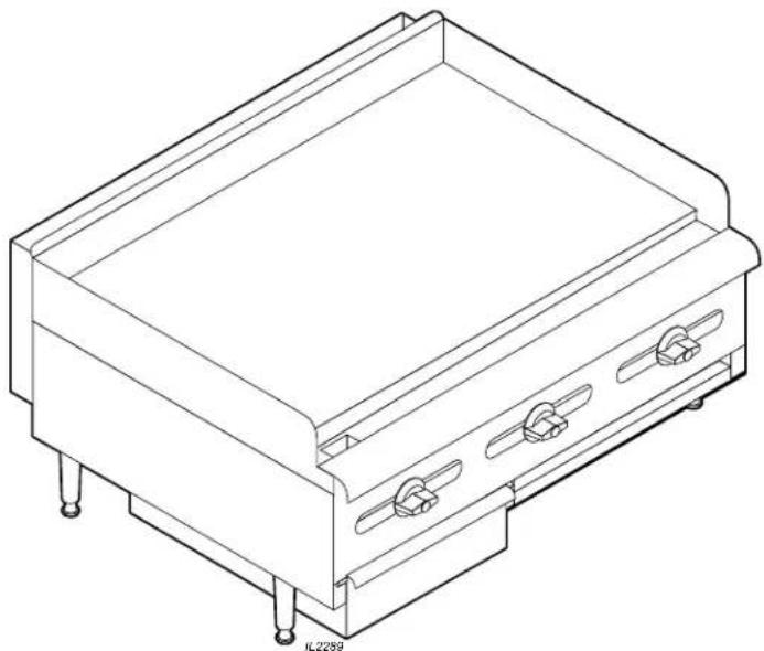
FEATURES & OPERATING CONTROLS
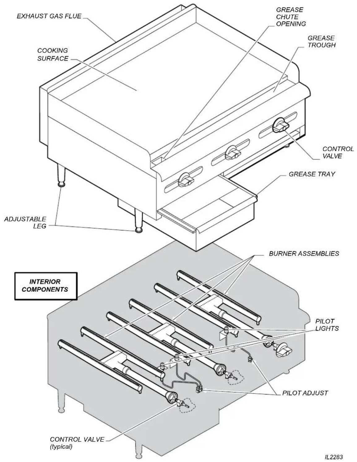
Fig. 1 Heavy Duty Gas Griddle - Features & Operating Controls
PRECAUTIONS AND GENERAL INFORMATION
This appliance is intended for use in commercial establishments only.
This appliance is intended to prepare food for human consumption.
No other use is recommended or authorized by the manufacturer or its agents.
This appliance must be installed by a technician qualified and certified or licensed to install gas-fired equipment. A licensed technician must perform the initial start-up and adjustment of the appliance.
Operators of this appliance must be familiar with the appliance use, limitations and associated restrictions. Operating instructions must be read and understood by all persons using or installing this appliance.
Cleanliness of this appliance is essential to good sanitation. Read and follow all included cleaning instructions and schedules to ensure the safety of the food product.
DO NOT submerge appliance or burners in water. This appliance is not jet stream approved. DO NOT direct water jet or steam jet at this appliance, or at any control. DO NOT splash or pour water on, in or over any controls. DO NOT wash counter around this appliance with water jet. Burners which have become wet must be thoroughly dried before use.
Griddle surface will be very hot when in use. Contact will cause severe injury.
This appliance must be operated with the supplied 4" legs properly installed.
Do not operate this appliance if the smell of gas is present. Turn off all gas supply valves and move to a remote location to call your Authorized Wells Service Agent for service.
The technical content of this manual, including any parts breakdown illustrations and/or adjustment procedures, is intended for use by qualified technical personnel only.
Any procedure which requires the use of tools must be performed by a qualified technician.
This manual is considered to be a permanent part of the appliance. This manual and all supplied instructions, diagrams, schematics, parts breakdown illustrations, notices and labels must remain with the appliance if it is sold or moved to another location.

WARNING: FIRE HAZARD
All servicing of the gas supply and combustion components of this appliance must be performed by a technician trained and certified in the maintenance of gas appliances.
Improper servicing of gas equipment can result in fire and explosion.

CAUTION: HOT SURFACE
Exposed surfaces can be hot to the touch and may cause burns.
AGENCY LISTING INFORMATION
This appliance conforms to NSF Standard 4 for sanitation only if installed in accordance with the supplied Installation Instructions and maintained according to the instructions in this manual.
This appliance meets ANSI Z.83.11 specifications for gas-fired food service equipment.
This appliance is Canadian Standards Association design certified for gas operation

STD4

INSTALLATION
NOTE: DO NOT discard the carton or other packing materials until you have inspected the appliance for hidden damage and tested it for proper operation. Refer to SHIPPING DAMAGE CLAIM PROCEDURE on the inside front cover of this manual.

DANGER: HEALTH HAZARD
This appliance must be properly ventilated. Failure to provide and maintain proper ventilation of exhaust gasses can result in severe injury or death.
WARNING: FIRE HAZARD
Do not store gasoline or any other flammable or combustible material near this appliance. The open flame can cause such materials to ignite.
The area where the griddle is installed must be kept clear of combustibles and flammables. This includes mops, rags, grease, wrapping paper and electric cords.
NOTICE: Manufacturer's warranty on this griddle is in effect only when the griddle is installed in accordance with these instructions and local codes and ordinances or, in the absence of local codes, the National Fuel Gas Code, ANSI Z223.1 (current edition). The manufacturer of this griddle assumes no liability for any damage or injury resulting from failure to comply with this notice.
UNPACKING & INSPECTION
Carefully remove the appliance from the carton. Remove all protective plastic film, packing materials and accessories from the appliance before connecting performing any installation procedure.
Carefully read all instructions in this manual and the Installation Instruction Sheet packed with the appliance before starting any installation.
Read and understand all labels and diagrams attached to the appliance.
Carefully account for all components and accessories before discarding packing materials. Store all accessories in a convenient place for later use.
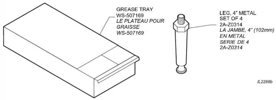
COMPONENTS
Dual Burner (-2430G, 2 ea.; -3630G, 3 ea.; -4830H, 4 ea.)
Adjustable Legs (set of 4)
Grease Tray (-2430G, 1 ea.; -3630G, 1 ea.; -4830H, 2 ea.)
SETUP
Setup the griddle only on a firm, level, non-combustible surface. Verify local codes for requirements. Concrete, tile, terrazzo or metal surfaces are recommended. Metal or tile over combustible material may not meet code for non-combustible surfaces.
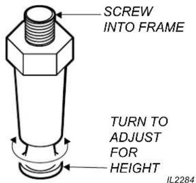
Install the provided adjustable legs, one on each corner of the appliance, in the holes provided. Verify that the unit sits firmly on ALL FOUR legs. With the adjustable legs, adjust as required to level the appliance. All four legs must be adjusted to firmly contact the countertop in order to prevent tipping.
Adequate clearance for air openings in the cabinet must be provided. Refer to the Installation
Instruction Sheet for required clearances. Maintain required clearances between the appliance and adjacent combustible surfaces.
The griddle must be installed in an area with sufficient make-up air for proper combustion, and must be installed such that the flow of combustion and ventilation air will not be obstructed.
When used with an exhaust fan, special precautions must be observed to avoid interference with the operation of the griddle, such as drafts and air starvation.
INSTALLATION
The installation of gas piping from the outlet side of the gas meter or service regulator to the griddle must be performed by a technician qualified and certified or licensed to install gas-fired equipment.
A licensed and qualified technician must perform the initial startup and adjustment of this appliance.
The installation of this gas-fired appliance must conform to local codes, or in the absence of such codes, with the current edition of National Fuel Gas Code ANSI Z223.1.
For use in the State of Massachusetts, this appliance must be installed in compliance with Massachusetts Fuel Gas and Plumbing Code CMR 248.
The installation of this gas-fired appliance must comply with applicable portions of NFPA 96 for ventilation. The current edition of NFPA 96 (Standard for the Installation of Equipment for the Removal of Smoke and Grease Laden Vapors from Commercial Cooking Equipment) specifies ventilation requirements to ensure the removal of exhaust gasses and products of combustion.
IT IS THE RESPONSIBILITY OF THE INSTALLER TO ENSURE THAT THIS GAS GRIDDLE INSTALLATION CONFORMS TO ALL APPLICABLE CODES AND ORDINANCES.
The venting of this appliance must not be obstructed, nor may such venting interfere with the flow of combustion air required for proper operation of the gas burners.
Additionally:
- The gas supply line used to connect the griddle to the gas supply system must be black iron pipe, or other material as approved by local ordinance for gas piping.
- Gas supply piping must be inside 3/4 diameter or greater.
- Use pipe sealant made specifically for gas piping on all pipe joints. Apply sealant sparingly to the male threads only. Sealant must be resistant to the action of LP gas.
- Verify that all supply piping is clean and free of obstructions, dirt, chips and pipe sealant compound prior to installation.
- All pipe joints must be checked for leaks before lighting. Leak checks should be performed with a soap and water solution. NEVER CHECK FOR LEAKS WITH AN OPEN FLAME.

DANGER: FIRE AND EXPLOSION HAZARD
NEVER use an open flame to check for gas leaks. Fire and explosion may result.

WARNING: RISK OF INJURY
Installation procedures must be performed by a qualified technician with full knowledge of all applicable gas-fired appliance codes. Failure can result in personal injury and property damage.
IMPORTANT:
All pipe joints must be checked for leaks before lighting. Leak checks should be performed with a soap and water solution.
IMPORTANT:
Information on the construction and installation of ventilating hoods may be obtained from the current edition of NFPA 96 Standard for the Installation of Equipment for the Removal of Smoke and Grease Laden Vapors from Commercial Cooking Equipment. Copies of this standard are available from the Nation Fire Protection Assn.:
NFPA
1 Batterymarch Park P.O.Box 9101
Quincy, MA 02269-9101
INSTALLATION

DANGER: FIRE AND EXPLOSION HAZARD
NEVER use an open flame to check for gas leaks. Fire and explosion may result.
IMPORTANT:
All pipe joints must be checked for leaks before lighting. Leak checks should be performed with a soap and water solution.

WARNING: FIRE HAZARD
This griddle is supplied with a gas pressure regulator. Failure to properly install the supplied regulator will result in an extremely hazardous condition.
Flow arrow stamped on body of regulator must point toward the griddle.
Vent hole must point UP.
IMPORTANT:
Verify fuel gas type. If the available fuel does not match the nameplate specification, exchange the hotplate for the correct type.
IMPORTANT:
The appliance and its individual manual shutoff valve must be disconnected from supply system piping during any pressure testing of that system at pressures in excess of 1/2 p.s.i. (3.5 kPa).
Also, the appliance must be isolated from the gas supply piping system by closing its individual manual shutoff valve during any pressure testing of the gas supply piping at test pressures equal to or less than 1/2 p.s.i. (3.5 kPa).
INSTALLING THE GAS GRIDDLE
Refer to the nameplate. Verify the fuel type and pressure, which must match the nameplate specifications. Connecting the hotplate to the wrong fuel type and/or pressure will compromise the safety and/or performance of the appliance.
BE SURE TO MAINTAIN REQUIRED CLEARANCES TO COMBUSTIBLE SURFACES.
The griddle must be placed in its final operational position and leveled front-to-back and side-to-side, with a spirit level, prior to beginning the gas piping installation. Re-check the level of the unit at the conclusion of the gas piping installation.
Each gas griddle is supplied with a separate gas pressure regulator, which must be installed on the manifold pipe protruding from the rear of the griddle. Ensure that the regulator is installed such that the flow arrow stamped on the body of the regulator points toward the griddle. Failure to properly install the supplied regulator will result in an extremely hazardous condition.
A moisture trap (drip leg) consisting of a tee, 4^ nipple pointing down, and cap must be installed upstream of the gas pressure regulator.
A manual gas shut-off valve may be required by local codes and is, in any case, strongly recommended. The shut-off valve must be installed between the gas supply piping and the gas pressure regulator.
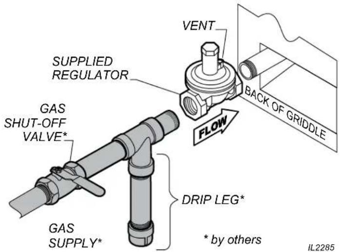
Fig. 2 Gas Supply Piping
INSTALLATION (continued)
SET GAS PRESSURE:
Gas pressure regulator is factory set.
SETPILOTFLAME:
Remove all burner control knobs, then remove the front panel.
The pilot adjustments are near the control valve for each set of burners.
Using a small, flat-blade screwdriver, turn the screw clockwise to decrease the flame size, or counter-clockwise to increase the flame size.
Adjust the pilot flame to 1/4 high. Test for operation: all sections of the burner must light without undue delay. Drafty conditions may require a higher flame to allow the pilot to remain lit.
Replace the front panel and all knobs before returning the unit to service.
ADJUST BURNER FLAME:
Remove all burner control knobs, then remove the front panel.
Turn an individual burner on.
Loosen the locking screw on the shutter.
Turn the shutter to admit more or less air as required. Adjust the air shutter until the flame is mostly blue in color.
Tighten the locking screw when finished. Replace the front panel and all knobs before returning the unit to service.
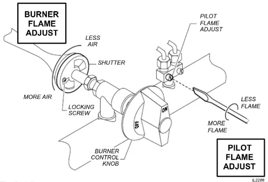
Fig. 3 Adjustments
IMPORTANT:
Adjustments must be performed by a qualified technician only.
IMPORTANT:
The griddle is shipped from the factory equipped for natural gas and adjusted for sea level to 2000 feet elevation. For conversion to LP / Propane, or for operation above 2000 feet elevation, contact your Authorized Wells Service Agency.
OPERATION

WARNING: FIRE HAZARD
IF YOU SMELL GAS:
DO NOT try to light any appliance.
DO NOT touch any electrical switch
DO NOT use any telephone in your building.
In the event a gas odor is detected, shut down the unit at the main gas shutoff valve and contact your local gas supplier from a neighboring location.
Follow the instructions received from the gas supplier immediately and exactly.
GENERAL OPERATIONAL NOTES
Carefully read the description of the griddle operation on the specification sheet.
Do NOT use this appliance if it has been submerged in water. Call a qualified technician to examine the appliance and to service or replace any component which has been submerged. Burners which have been allowed to become wet must be thoroughly dried before use.
For initial startup, and any time the gas supply has been shut-off, it may take several minutes to light the pilot while air in the piping and manifolds is purged.
The burner control knobs must be turned by hand only. Never use tools to turn the control knob. If the knob will not turn by hand, DO NOT attempt to force or repair it. Contact your Authorized Wells
Service Agency for repairs. Forced or improperly repaired valves pose the risk of fire and/or explosion.
Make sure burners, pilot burner and grease tray are properly installed before attempting to operate.
LIGHTING THE PILOT FLAME
Before lighting the pilot light, smell all around the appliance area for gas. Be sure to smell near floor level because some gas is heavier than air and will settle to the floor.
For initial startup, and any time the gas supply has been shut-off, it may take several minutes to light the pilot while air in the piping and manifolds is purged.
The pilot light must be lighted by hand:
Turn all control knobs to the full OFF position.
The pilot is located adjacent to one leg of the burner, and is accessible through the front panel opening.
Be sure the gas shut-off valve is ON and the appliance has had time for the air to be purged from the lines. Attempt to light the pilot every 15 seconds after the gas valve is turned on.
Light the pilot with a long match or fireplace lighter.
DO NOT use a cigarette lighter.
SHUT DOWN INSTRUCTIONS
Turn all burner knobs to OFF.
Turn all pilots OFF.
Turn the main gas supply OFF.
OPERATION
SEASON THE GRIDDLE SURFACE
As manufactured, the steel surface of your Wells griddle has microscopic pores. It is important to fill these pores with oil in order to provide a hard, non-stick cooking surface.
a. Preheat the griddle surface to 375^ (191^)
b. Spread a light film of cooking oil over the entire griddle surface
c. Allow the oil film to cook in for approximately 2 minutes, or until it smokes.
d. Wipe the griddle surface with a clean damp cloth until all oil is removed.
e. For new griddles, repeat this procedure 2-3 times until the griddle has a slick, clean surface.
OPERATION
Inspect the unit for cleanliness before use. Clean as necessary: See Cleaning Instructions, page 10.
Be sure the pilot light is lit before operation. See Lighting the Pilot Light, page 8.
The burner control knobs must be turned by hand only. Never use tools to turn the control knob.
The control used in this gas griddle provides a continuous range of settings from OFF to ON.
Light the burner by turning the control knob to the ON position until fire forms completely in all sections of the burner. Set the control knob to the desired position. The setting can be readjusted at any time.

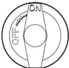
Fig. 4 Burner Control
WARNING: FIRE HAZARD
NEVER attempt to force or repair a stuck control valve.
Contact your Authorized Wells Service Agency for repairs.
Forced or improperly repaired valves pose the risk of fire and/or explosion.

WARNING: FIRE AND EXPLOSION HAZARD
If the pilot light should be extinguished, turn off the gas shut-off valve.
Allow the appliance to vent for five minutes
before attempting to relight.

CAUTION: HOT SURFACE
Exposed surfaces can be hot to the touch and may cause burns.
Cooking Recommendations:
Save energy by turning the temperature control knob OFF any time the griddle is not in use. Gas burners provide full heat instantly, making it unnecessary to leave the unit on during intermittent use.
CLEANING INSTRUCTIONS

WARNING: FIRE HAZARD
Shut off the gas supply valve before cleaning.

CAUTION: BURN HAZARD
Allow hotplate to cool completely before cleaning.
PREPARATION
Turn control valve to a low setting before cleaning. Allow griddle to cool to this lower setting before cleaning.
FREQUENCY
Daily
TOOLS
Bristle Brush
Clean Cloth or Sponge
Mild Detergent
Cleaner Formulated for Stainless Steel
Warm Water
IMPORTANT: DO NOT spill or pour water into controls.
DO NOT submerge griddle cabinet in water. Damage to internal components will occur.
Damage to internal components from water damage is NOT covered by warranty.
DO NOT steel wool or metal scouring pads to clean cabinet or grease tray.
Good sanitation is vital to the quality of the final food product. Be sure to clean in all corners and crevices where grease and other cooking debris can accumulate.
DAILY CLEANING
- Pour a small amount of water on the griddle surface and let it "sizzle".
- Clean the griddle surface. Use a pumice stone or griddle brick to scrape food waste. Clean the griddle surface down to bright metal. Wipe off any remaining powder residue.
IMPORTANT: NEVER USE STEEL WOOL TO CLEAN THE GRIDDLE SURFACE!
DO NOT use detergent or oven cleaner to clean the griddle surface.
3. Use a soft-bristled fiber brush in a circular motion to remove any remaining food particles.
4. Turn temperature control to OFF. Allow the griddle surface to cool, then wipe the surface with a clean cloth. Dry the griddle surface thoroughly.
IMPORTANT: Season the cooking surface after each cleaning. See page 9.
- At least once each day, the grease trough must be thoroughly cleaned. Using a scraper, remove all grease and food waste from the grease trough by pushing it down the waste hole and into the grease tray.
- After scraping all cooking waste from grease trough into the grease tray, take the grease drawer to the kitchen cleaning area and properly dispose of all waste.
a. Clean drawer with hot water and a mild detergent.
b. Dry drawer thoroughly and reinstall in griddle.
- Wipe down exterior of griddle cabinet with a clean cloth and non-abrasive cleanser. Rinse thoroughly with water and a clean cloth. Dry with a soft clean cloth.
Procedure is complete.
CLEANING INSTRUCTIONS
PREPARATION
Turn gas shut-off valve OFF.
Allow griddle to cool before cleaning.
FREQUENCY
As Needed
TOOLS
Bristle Brush
Clean Cloth or Sponge
Mild Detergent
Cleaner Formulated for Stainless Steel
Warm Water

WARNING: FIRE HAZARD
Shut off the gas supply valve before cleaning.
CLEANING BURNERS
If one or more individual flame openings does not light, or if the flame is intermittent or uneven, the burner may need to be cleaned.
Turn shut-off valve OFF. Remove all control knobs and remove front panel.
Note position of burner assemblies in cabinet. Remove burners.
Examine burner assemblies. Note position of air shutters before cleaning. Clean food particles from burners with warm water, mild detergent and a bristle brush. Rinse by wiping with a soft cloth dampened with clean water. Wipe exterior surfaces dry with a soft clean cloth. Allow burners to air dry so that interior passages are completely free of water.
Examine burners to be sure the air shutters are in their proper position. Reinstall burners with flame openings "up". The venturi / air shutter slides over the nozzle of the control valve. The pegs on the rear of the burner set in corresponding notches in the rear burner support bracket. The pegs on the front of the burner set on the front support bracket.
Turn shut-off valve ON and light pilot light.
Reinstall front panel and all control knobs.
Test all burners for proper operation.
Procedure is complete.
IMPORTANT: DO NOT spill or pour water into burners or controls,
DO NOT submerge griddle cabinet in water. Damage to internal components will occur.
Damage to internal components from water damage is NOT covered by warranty.
TROUBLESHOOTING
| SYMPTOM POSSIBLE CAUSE SUGGESTED REMEDY | ||
| Pilot will not light | Gas supply off Check main / unit gas valves | |
| Air in lines | Turn pilot valve on. Attempt to light pilot every 15 sec. | |
| Pilot valve not on Turn pilot valve on / adjust | ||
| Burners won't light | Gas supply off Check main / unit gas valves | |
| Air in lines | Turn gas valve on. Attempt to light pilot every 15 sec. | |
| Pilot burner not lit | Turn off gas - allow unit to vent for 5 minutes. Turn gas back on and light pilot | |
| One burner assembly won't light | Control not on | Turn control knob to ON. Set to desired setting when lit |
| Water in burner Remove burner and dry thoroughly | ||
| Damaged temperature control, burner or other internal component | Contact Authorized Wells Service Agency for repairs | |
| Portions of a burner won't light or have erratic flame | Burner wet or flame opening(s) clogged | Clean and dry burner |
| Burner not hot enough | Temperature control not set Adjust | just for desired temperature |
| Shutter or nozzle out of adjustment | Contact qualified technician for adjustment | |
| Damaged temperature control, burner or other internal component | Contact Authorized Wells Service Agency for repairs | |
PARTS & SERVICE
DESCRIPTION
LEGS, ADJUSTABLE 4" METAL (SET of 4) WS-20563
PART
IMPORTANT: Use only
factory authorized service parts and replacement filters.
For factory authorized service, or to order factory authorized replacement parts, contact your Wells authorized service agency, or call:
Wells Manufacturing
10 Sunnen Dr., St. Louis MO 63143 USA
Service Dept.
phone: (314) 678-6314
fax: (314) 781-2714
Service Parts Department can supply you with the name and telephone number of the WELLS authorized service agency nearest you.
CUSTOMER SERVICE DATA
please have this information available if calling for service
RESTAURANT LOCATION
INSTALLATION DATE TECHNICIAN
SERVICE COMPANY
ADDRESS STATE ZIP
TELEPHONE NUMBER ( ) -
EQUIPMENT MODEL NO.
EQUIPMENT SERIAL NO.
FUEL (check one) Natural Gas PROpane /
GAS ORIFICE CONVERSION CHART
| CONVERSION CHART - GRIDDLE | ||
| NATURAL GAS ELEVATION LP / PROpane | ||
| - SEA LEVEL - 2000' KIT NO. 2J-Y7250 | ||
| KIT NO. 2Z-23149 2 000' - 2,999' KIT NO. 2Z-23155 | ||
| KIT NO. 2Z-23150 | 3,000' - 3,999' | KIT NO. 2Z-23156 |
| 4,000' - 4,999' | ||
| KIT NO. 2Z-23151 | 5,000' - 5,999' | |
| 6,000' - 6,999' | ||
| KIT NO. 2Z-23152 | 7,000' - 7,999' | |
| 8,000' - 8,999' | KIT NO. 2Z-23157 | |
| KIT NO. 2Z-23153 | 9,000' - 9,999' | |
| ABOVE 10,000' | ||
GRAPHIQUE DE CONVERSION - LE CAPUCHON D'ORIFICE
| GRAPHIQUE DE CONVERSION - GRILL PROFESSIONNEL | ||
| Gaz naturel ELEVATION PROPANE / GPL | ||
| - NIVEAU DE LA MER - 2000' (610M) KIT NO. 2J-Y7250 | ||
| KIT NO. 2Z-23149 2,000' - 2,999' (610M - 914M) KIT NO. 2Z-2315 | ||
| KIT NO. 2Z-23150 | 3,000' - 3,999' (915M - 1219M) | KIT NO. 2Z-23156 |
| 4,000' - 4,999' (1220M - 1524M) | ||
| KIT NO. 2Z-23151 | 5,000' - 5,999' 1525M - 1829M) | |
| 6,000' - 6,999' (1830M - 2133M | ||
| KIT NO. 2Z-23152 | 7,000' - 7,999' (2134M - 2438M) | |
| 8,000' - 8,999' (2439M - 2743M) | KIT NO. 2Z-23157 | |
| KIT NO. 2Z-23153 | 9,000' - 9,999' (2744M - 3048M) | |
| AU-DESSUS DE 10,000' (3049M) | ||
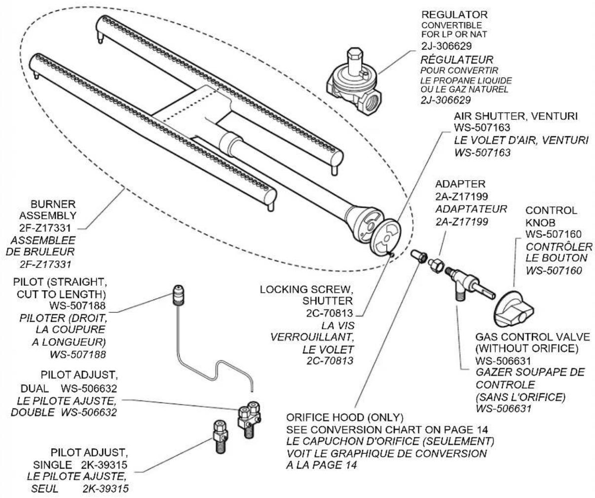
EXPLODED VIEW & PARTS LIST
LA VUE EXPLOSEE & LES PARTIES ENUMERENT
HDG-SERIES HEAVY-DUTY GAS GRIDDLE SERVICE COMPONENTS
COLLECTION-HDG GRILL DE GAZ TRES RESISTANT COMPOSANTS DISPONIBLES
MANUEL DE L'UTILISATEUR
WELLS GRILL PROFESSIONNEL
MODELES
HDG2430G
HDG3630G
HDG4830G
HDG6030G
Compend :
INSTALLATION,
MODE D'EMPLOI
&ENTRETIEN
Modèle HDG-3630G
POUR VOTRE SECURITE
CONFORMITE AU CODE RELATIF AUX APPAREILS A GAZ
Wells Bloomfield proudly supports CFESA Commercial Food Equipment Service Association
SERVICE TRAINING - QUALITY SERVICE

CUSTOMER SATISFACTION

WELLS MANUFACTURING
10 Sunnen Dr., St. Louis, MO 63143
telephone: 314-678-6314
fax: 314-781-2714
www.wellsbloomfield.com