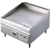
WG3048G - Grill plate Wells - Free user manual and instructions
Find the device manual for free WG3048G Wells in PDF.


User questions about WG3048G Wells
0 question about this device. Answer the ones you know or ask your own.
Ask a new question about this device
Download the instructions for your Grill plate in PDF format for free! Find your manual WG3048G - Wells and take your electronic device back in hand. On this page are published all the documents necessary for the use of your device. WG3048G by Wells.
USER MANUAL WG3048G Wells
265 Hobson Street, Smithville, Tennessee 37166
telephone: 800-264-7827
www.wells-mfg.com
natural_image
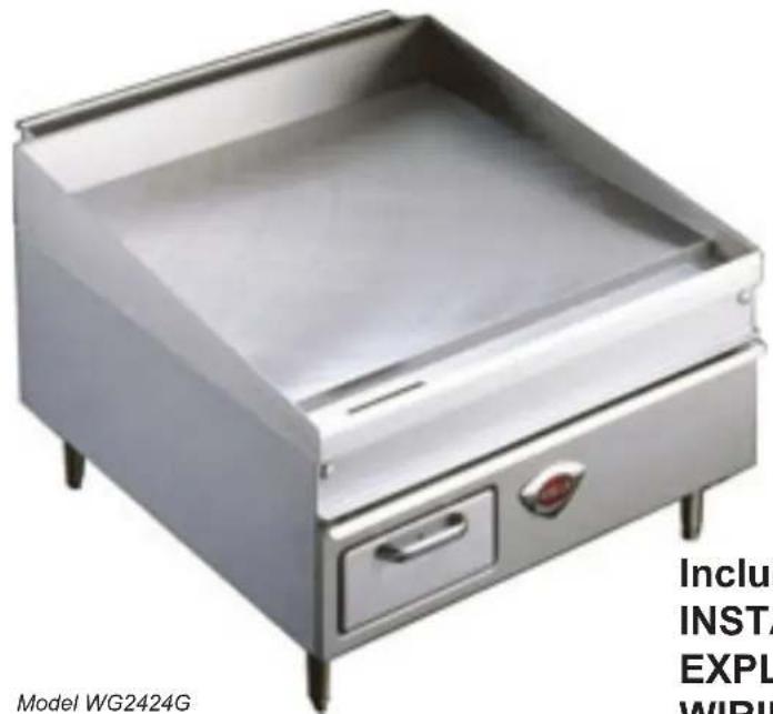
Exterior view of a stainless steel model grater with open lid and side drawer (no text or symbols visible)OWNERS MANUAL
COUNTERTOP
GAS
GRIDDLES
MODELS
WG2424G
WG2436G
WG3036G
WG3048G
Includes
INSTALLATION, USE & CARE
EXPLODED VIEW & PARTS LIST
WIRING DIAGRAM
FOR YOUR SAFETY
Do not store gasoline or other flammable liquids
in the vicinity of this or any other appliance.
WARNING:
Improper installation, adjustment, alteration, service or maintenance can cause property damage, injury or death. Read the installation, operating and maintenance instructions thoroughly before installing or servicing this equipment.
IMPORTANT:
The purchaser of this equipment must post in a prominent location instructions to be followed in the event the user smells gas. This information shall be obtained by consulting the local gas supplier.
IMPORTANT: DO NOT DISCARD THIS MANUAL
This manual is considered to be part of the appliance and is to be given to the OWNER or MANAGER of the restaurant, or to the person responsible for TRAINING OPERATORS of this appliance. Additional manuals are available from your WELLS DEALER.

natural_image
Silhouette of a person reading a book (no text or symbols visible)THIS MANUAL MUST BE READ AND UNDERSTOOD BY ALL PERSONS USING OR INSTALLING THIS APPLIANCE. Contact your WELLS DEALER if you have any questions concerning installation, operation or maintenance of this equipment.
LIMITED WARRANTY STATEMENT
LIMITED EQUIPMENT WARRANTY
Wells Manufacturing warrants to the original purchaser of new Wells products to be free from defects in material or workmanship, under normal and proper use and maintenance service as specified by Wells and upon proper installation and start-up in accordance with the instructions supplied with each Wells unit. Wells' obligation under this warranty is limited to a period of one [1] year beginning from the date of original installation. The warranty period begins upon the earlier of the date of original installation or up to six [6] months after the original shipment, from the factory, of the covered product. Defects that occur as a result of normal use, within the time period and limitations defined in this warranty, will at Wells' discretion have the parts replaced or repaired by Wells or a Wells-authorized service agency.
THIS WARRANTY IS SUBJECT TO ALL LISTED CONDITIONS
Repairs performed under this warranty are to be performed by a Wells authorized service agency. Wells will not be responsible for charges incurred or service performed by non-authorized repair agencies. In all cases, the nearest Wells-authorized service agency must be used. Wells will be responsible for normal labor charges incurred in the repair or replacement of a warranted product within 50 miles (80.5 km) of an authorized service agency. Time and expense charges for anything beyond that distance will be the responsibility of the owner. All labor will need to be performed during regular service hours. Any overtime premium will be charged to the owner. For all shipments outside the U.S.A. and Canada, please see the International Warranty for specific details. It is the responsibility of the owner to inspect and report any shipping damage claims, hidden or otherwise, promptly following delivery. No mileage or travel charges will be honored on any equipment that is deemed portable. In general, equipment with a cord and plug weighing less than 50 lb. (22.7 kg) is considered portable and should be taken or shipped to the closest authorized service agency, transportation prepaid.
CONTACT
Should you require any assistance regarding the operation or maintenance of any Wells Manufacturing; phone or email our service department. In all correspondence provide the model number and serial number of the unit needing service; include the voltage or gas type.
Normal Business Hours: 8:00 a.m. to 4:30 p.m. Central Telephone: 800-264-7827 Tech Service Option 2
Email: TechService@partstown.com
www.Wells-Mfg.com
| PROD UCTS PARTS LABOR | ||
| Universal Ventless Hoods (WVU) 1 year 1 year | ||
| Canopy Ventless Hoods (WVC) | 1 year 1 year | |
| *Universal ventless hoods and/or canopy ventless hoods purchased with approved Star Holdings electric equipment.**Star Holdings approved electric equipment purchased and installed a under ventless hood.*** Universal ventless hood and Star Holdings electric equipment must be on the same po and listed on the ventless start-up document for the 2-year warranty to apply. | 2 years 2 years | |
| "Cook'n Hold equipment (HW-106D) | 2 years 2 years | |
| Cast iron gates, burners and burner shields | 1 year | |
| Original Wells parts sold to repair Wells equipment | 90 days | |
WARRANTY EXCLUSIONS
THE FOLLOWING WILL NOT BE COVERED UNDER WARRANTY.
Wells' sole obligation under this warranty is limited to either repair or replacement parts, subject to the additional limitations detailed below. This warranty neither assumes nor authorizes any person to assume obligations other than those expressly covered by this warranty.
- Any product which has not been used, maintained, or installed in accordance with the directions published in the appropriate installation sheet and/or owner's manual, including incorrect gas or electrical connection. Wells is not liable for any unit which has been mishandled, abused, misapplied, subjected to harsh chemicals, modified by unauthorized personnel, damaged by flood, fire, or other acts of nature [or God], or which have an altered or missing serial number.
- Installation, labor, and job checkouts, calibration of heat controls, air and gas burner/bypass/pilot adjustments, gas or electrical system checks, voltage and phase conversions, cleaning of equipment, or seasoning of griddle surface.
- Replacement of fuses or resetting of circuit breakers, safety controls, or reset buttons.
- Replacement of broken or damaged glass components, quartz heating elements, and light bulbs.
- Labor charges for all removable and consumable parts in gas charbroilers and hotplates, including but not limited to burners, grates, and radiants.
- Any labor charges incurred by delays, waiting time, or operating restrictions that hinder a service technician's ability to perform service.
- Replacement of parts that fail or are damaged due to normal wear or labor for replacement of parts that can be replaced during a daily cleaning routine, such as but not limited to silicone belts, PTFE non-stick sheets, control labels, knobs, bulbs, fuses, quartz heating elements, baskets, racks, and grease drawers.
- Any economic loss of business or profits.
- Non-OEM parts. Use of non-OEM parts without Wells' approval will void the warranty.
- Units exceeding one [1] year from original installation date.
ADDITIONAL WARRANTIES
- Specific/chain-specific equipment may have additional and/or extended warranties.
The foregoing warranty is in lieu of any and all other warranties expressed or implied and constitutes the entire warranty.
TABLE OF CONTENTS
WARRANTY xi
SPECIFICATIONS 1
FEATURES & OPERATING CONTROLS 2
PRECAUTIONS & GENERAL INFORMATION 3
INSTALLATION 4
INITIAL ADJUSTMENT 8
OPERATION 10
CLEANING INSTRUCTIONS
Standard and GroovedGriddles 12
Chrome-Plated griddles 13
TROUBLESHOOTING SUGGESTIONS 14
WIRING DIAGRAM 15
EXPLODED VIEW & PARTS LIST 16
PARTS & SERVICE 27
CUSTOMER SERVICE DATA 27
INTRODUCTION
Thank You for purchasing this Wells Manufacturing appliance.
Proper installation, professional operation and consistent maintenance of this appliance will ensure that it gives you the very best performance and a long, economical service life.
This manual contains the information needed to properly install this appliance, and to use and care for the appliance in a manner which will ensure its optimum performance.
SPECIFICATIONS
| MODEL | COOKING SURFACE | FUEL | MAINIFOLD PRESSURE | BTU/HR /BURNER | BTU/HR TOTAL |
| WG2424G | 23 7/8" x 20 1/2"2 BURNER | Natural Gas | 5.0" W.C. | 25,000 BTU/hr | 50,000 BTU/hr |
| Propane | 10.0" W.C. | ||||
| WG2436G | 35 7/8" x 20 1/2"3 BURNER | Natural Gas | 5.0" W.C. | 25,000 BTU/hr | 75,000 BTU/hr |
| Propane | 10.0" W.C. | ||||
| WG3036G | 35 7/8" x 24"3 BURNER | Natural Gas | 5.0" W.C. | 25,000 BTU/hr | 75,000 BTU/hr |
| Propane | 10.0" W.C. | ||||
| WG3046G | 47 3/4" x 24"4 BURNER | Natural Gas | 5.0" W.C. | 25,000 BTU/hr | 100,000 BTU/hr |
| Propane | 10.0" W.C. |
FEATURES & OPERATING CONTROLS
text_image
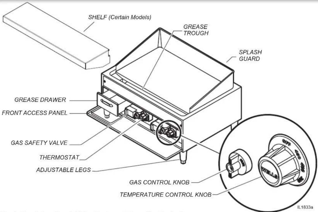
SHELF (Certain Models) GREASE TROUGH SPLASH GUARD GREASE DRAWER FRONT ACCESS PANEL GAS SAFETY VALVE THERMOSTAT ADJUSTABLE LEGS GAS CONTROL KNOB TEMPERATURE CONTROL KNOB IL1833aFig. 1 Countertop Gas Griddle - Features & Operating Controls
| FRONT ACCESS PANEL Allows access to gas control valve and theremature control thermostat. | |
| THERMOSTAT TEMP.CONTROL KNOB | Energizes gas valve and allows burners to light based on temp. control knob setting and temperature sensed at griddle surface |
| Each section of the griddle is individually controllable. | |
| Dial position is an indication of the temperature setting. The actual temperature at the griddle surface will vary, depending upon the initial type and temperature of the product, and other variables. | |
| GAS SAFETY VALVE GASCONTROL VALVE | Provides ignition pilot flame. Allows fuel to burners only when pilot flame is established. |
| GREASE TROUGH | Extra-wide trough with radiused corners for easier cleaning. Trough slopes toward a large waste hole that empties into the removable grease drawer. |
| GREASE DRAWER Large | capacity drawer is removable through the front for easy cleaning. |
| REMOVABLE SPLASH GUARD | Stainless steel splash guard simplifies griddle maintenance and helps to keep grease from splattering onto adjacent walls and equipment |
| NAMEPLATE(located on rear of unit) | Lists manufacturer's information, model and serial number. Also lists fuel requirement specifications. |
PRECAUTIONS AND GENERAL INFORMATION
This appliance is intended for use in commercial establishments only.
This appliance is intended to prepare food for human consumption. No other use is recommended or authorized by the manufacturer or its agents.
This griddle must be installed by a technician qualified and certified or licensed to install gas-fired equipment. A licensed technician must perform the initial startup and adjustment of this appliance.
Operators of this appliance must be familiar with the appliance use, limitations and associated restrictions. Operating instructions must be read and understood by all persons using or installing this appliance.
Cleanliness of this appliance is essential to good sanitation. Read and follow all included cleaning instructions and schedules to ensure the safety of the food product.
DO NOT submerge griddle or burners in water. DO NOT splash or pour water into interior of griddle. Burners which have been allowed to become wet must be thoroughly dried before use.
Griddle must be operated with the supplied legs properly installed.
The technical content of this manual, including any parts breakdown illustrations and/or adjustment procedures, is intended for use by qualified technical personnel only.
Any procedure which requires the use of tools must be performed by a qualified technician.
This manual is considered to be a permanent part of the appliance. This manual and all supplied instructions, diagrams, schematics, parts breakdown illustrations, notices and labels must remain with the appliance if it is sold or moved to another location.
This appliance is made in the USA. Unless otherwise noted, this appliance has American sizes on all hardware.

WARNING: FIRE HAZARD
In the event a gas odor is detected, shut down the unit at the main gas shutoff and contact your local gas supplier from a neighboring location for service.

CAUTION: FALL HAZARD
DO NOT stand or sit on the griddle.
CAUTION: FALL HAZARD
DO NOT use the griddle as a stool or ladder.
INSTALLATION
NOTE: DO NOT discard the carton or other packing materials until you have inspected the appliance for hidden damage and tested it for proper operation. Refer to SHIPPING DAMAGE CLAIM PROCEDURE on the inside front cover of this manual.
DANGER: HEALTH HAZARD
This appliance must be properly ventilated. Failure to provide proper ventilation of exhaust gasses can result in severe injury and death.

WARNING: FIRE HAZARD
Do not store flammable or combustible materials near this appliance. The open flame of this appliance can cause such materials to ignite.
NOTICE:
Manufacturer's warranty on this griddle is in effect only when the appliance is installed and operated in accordance with these instructions and local codes and ordinances or, in the absence of local codes, the National Fuel Gas Code, ANSI Z223.1 (current edition). The manufacturer of the griddle assumes no liability for any damage resulting from failure to comply with this notice.
UNPACKING & INSPECTION
Carefully remove the griddle from the carton. Remove all protective plastic film, packing materials and accessories from the griddle before connecting the griddle to fuel gas or otherwise performing any installation procedure.
Carefully read all instructions in this manual and the Installation Instruction Sheet packed with the griddle before starting any installation.
Read and understand all labels and diagrams attached to the griddle.
Carefully account for all components and accessories before discarding packing materials. Store all accessories in a convenient place for later use.
Thoroughly clean the appliance before use. See Cleaning Instructions, page 12.
SETUP
Supplied legs must be properly installed. Once installed, the legs should NOT be removed.
The griddle must be leveled with a spirit level in its final operational position, prior to beginning the gas piping installation.
Setup the griddle only on a firm level surface. Non-combustible material (e.g. metal, terrazzo) is required.
Adequate clearances for air openings into the cabinet must be provided. Maintain at least 3" clearance from adjacent surfaces.
The griddle must be installed in an area with sufficient make-up air for proper combustion, and must be installed such that the flow of combustion and ventilation air will not be obstructed.
When used with an exhaust fan, special precautions must be observed to avoid interference with the operation of the griddle, such as drafts and air starvation.
The current edition of NFPA 96 (Standard for the Installation of Equipment for the Removal of Smoke and Grease Laden Vapors from Commercial Cooking Equipment) specifies ventilation requirements to ensure the removal of exhaust gasses and products of combustion. IT IS THE RESPONSIBILITY OF THE INSTALLER TO ENSURE THAT THIS GAS GRIDDLE INSTALLATION CONFORMS TO ALL APPLICABLE CODES AND ORDINANCES.
DO NOT store flammable or combustible materials on, in or near the griddle.
The area where the griddle is installed must be kept clear of combustibles and flammables. This includes mops, rags, grease, wrapping paper and electric cords.
INSTALLATION
The installation of gas piping from the outlet side of the gas meter or service regulator to the griddle must be performed by a technician qualified and certified or licensed to install gas-fired equipment.
A licensed and qualified technician must perform the initial startup and adjustment of this appliance.
The installation of this gas-fired appliance must conform to local codes, or in the absence of such codes, with the current edition of National Fuel Gas Code ANSI Z223.1.
For use in the State of Massachusetts, this appliance must be installed in compliance with Massachusetts Fuel Gas and Plumbing Code CMR 248.
The installation of this gas-fired appliance must comply with applicable portions of NFPA 96 for ventilation.
The venting of this appliance must not be obstructed, nor may such venting interfere with the flow of combustion air required for proper operation of the gas burners.
Additionally:
- The gas supply line used to connect the griddle to the gas supply system must be black iron pipe, or other material as approved by local ordinance for gas piping.
- Gas supply piping must at least 3/4" NPT.
- Use pipe sealant made specifically for gas piping on all pipe joints. Apply sealant sparingly to the male threads only. Sealant must be resistant to the action of LP gas. Teflon pipe thread tape is NOT recommended for gas installations.
- Verify that all supply piping is clean and free of obstructions, dirt, chips and pipe sealant compound prior to installation.
- All pipe joints must be checked for leaks before lighting. Leak checks should be performed with a soap and water solution. NEVER CHECK FOR LEAKS WITH AN OPEN FLAME.
DANGER: FIRE AND EXPLOSION HAZARD
NEVER use an open flame to check for gas leaks. Fire and explosion may result.
IMPORTANT:
All pipe joints must be checked for leaks before lighting. Leak checks should be performed with a soap and water solution.
IMPORTANT:
Information on the construction and installation of ventilating hoods may be obtained from the current edition of NFPA 96 Standard for the Installation of Equipment for the Removal of Smoke and Grease Laden Vapors from Commercial Cooking Equipment. Copies of this standard are available from the Nation Fire Protection Assn.:
NFPA
1 Batterymarch Park
P.O. Box 9101
Quincy, MA 02269-9101
INSTALLATION

DANGER: FIRE AND EXPLOSION HAZARD
NEVER use an open flame to check for gas leaks. Fire and explosion may result.
IMPORTANT:
All pipe joints must be checked for leaks before lighting. Leak checks should be performed with a soap and water solution.

WARNING: FIRE HAZARD
This griddle is supplied with a gas pressure regulator. Failure to properly install the supplied regulator will result in an extremely hazardous condition.
Flow arrow stamped on body of regulator must point toward the griddle.
Regulator adjusting screw and vent hole must point UP.
IMPORTANT:
Verify fuel gas type. If the available fuel does not match the nameplate specification, exchange the griddle for the correct type. DO NOT attempt to modify a unit in the field to accept a different fuel.
IMPORTANT:
Avoid damage to the regulator: if the gas supply piping system is pressure tested at pressures exceeding 1/2 psig (3.45kPa), the griddle must be isolated or disconnected from the gas piping system for the duration of the test.
INSTALLING THE GRIDDLE
Refer to the nameplate. Verify the fuel type and pressure, which must match the nameplate specifications. Connecting the griddle to the wrong fuel type and/or pressure will compromise the safety and/or performance of the appliance.
The griddle must be placed in its final operational position and leveled front-to-back and side-to-side, with a spirit level, prior to beginning the gas piping installation. Re-check the level of the unit at the conclusion of the gas piping installation.
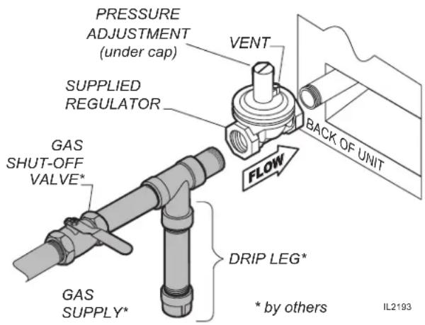
Each gas griddle is supplied with a separate gas pressure regulator. The supplied regulator must be used, and must be installed on the manifold pipe protruding from the rear of the griddle. Ensure that the regulator is installed such that the flow arrow stamped on the body of the regulator points toward the griddle. Failure to properly install the supplied regulator will result in an extremely hazardous condition.
A moisture trap (drip leg) consisting of a tee, 4" nipple pointing down, and cap must be installed upstream of the gas pressure regulator.
A manual gas shut-off valve may be required by local codes and is, in any case, strongly recommended. The shut-off valve must be installed between the gas supply piping and the gas pressure regulator.
It is the responsibility of the gas piping installer to identify the code requirement for a shut-off valve.
Shut-off valves, moisture trap and all associated piping must be supplied by the gas piping installer.
text_image
PRESSURE ADJUSTMENT (under cap) VENT SUPPLIED REGULATOR GAS SHUT-OFF VALVE* GAS SUPPLY* FLOW DRIP LEG* * by others IL2193 BACK OF UNITFig. 2 Gas Supply Piping
INSTALLATION
GAS PIPE PRESSURE TESTING
The main piping system must be capable of supplying the griddle with sufficient volume/flow of fuel to satisfy the maximum operational input requirements.
Make sure the supply piping system has been pressure tested before the regulator and griddle are connected. If the system must be re-tested, be sure the regulator is isolated by a manual shut-off valve, in order to prevent damage to the regulator and gas griddle valves.
Piping and connections should be leak tested using a water/soap solution. DO NOT USE FLAME TO CHECK FOR GAS LEAKS.
Equipment gas pressure (the pressure downstream of the pressure regulator) may be tested by adapting a water column gauge to the plugged ports on the main gas manifold. The pressure regulator supplied with the Gas Griddle is factory set for a nominal gas pressure of 5" w.c.
Be sure to remove any adapters, and to re-plug and leak check the port before returning the griddle to service. Leak testing should be performed using a water/soap solution. DO NOT USE FLAME TO CHECK FOR GAS LEAKS.
GAS SUPPLY FLOW VOLUME TESTING REQUIREMENTS
While testing for adequate gas pressure, be sure all other gas appliances that utilize the same source piping are in operation with burners ON in order to ensure accurate operational conditions. If flow volume in the system piping is marginal, and should other appliances on that system not be consuming gas while testing for pressure, the test results may be inaccurate.
IMPORTANT:
PRESSURE TESTING MUST BE PERFORMED BY A QUALIFIED TECHNICIAN ONLY.
NOTE: The maximum inlet pressure from the supply piping must not exceed 12 p.s.i (14" W.C.) Pressure above this limit will damage the regulator and gas valves.
Port for measuring outlet gas pressure is located on the manifold. Remove the grease drawer to gain access. Remove the allen head plug sealing the test port, then connect the hose of a water column gauge.
Be sure to reinstall the allen head plug at the conclusion of testing.
INITIAL ADJUSTMENT
IMPORTANT:
PRESSURE ADJUSTMENT MUST BE PERFORMED BY A QUALIFIED TECHNICIAN ONLY.
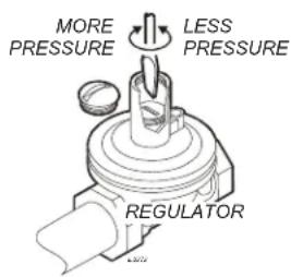
text_image
MORE PRESSURE LESS PRESSURE REGULATORFig. 3 Adjust gas pressure
IMPORTANT:
FLAME ADJUSTMENT MUST BE PERFORMED BY A QUALIFIED TECHNICIAN ONLY.
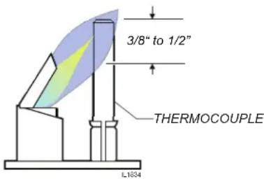
text_image
3/8" to 1/2" THERMOCOUPLE L1834Fig. 4 Adjust pilot flame
IMPORTANT:
FLAME ADJUSTMENT MUST BE PERFORMED BY A QUALIFIED TECHNICIAN ONLY.
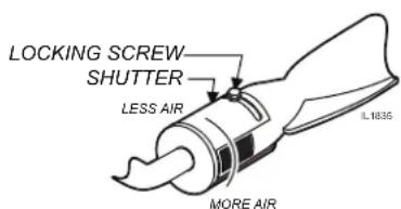
text_image
LOCKING SCREW SHUTTER LESS AIR MORE AIR IL1835Fig. 5 Adjust burner flame
PURGING AIR FROM GAS LINES
Air must be purged from the gas lines for the initial startup. Turn the knob on the safety valve to PILOT, press and hold until a flame can be established at the pilot burner. Repeat for each pilot.
Caution must be taken to ensure that no raw gas is present in the surrounding area when attempting to place the Griddle into operation.
SET GAS PRESSURE:
Turn the gas shut-off valve OFF.
Remove the plug in the gas pressure measurement tap and attach a manometer. Turn the shut-off valve ON. Light the pilot light and turn both gas control valves to HI.
Remove the cap from the pressure regulator. Turn the adjusting screw clockwise to increase pressure; counter-clockwise to decrease pressure. Adjust the gas pressure regulator for:
5" water column (natural gas); or, 10" water column (propane).
When finished, replace cap on regulator, turn shut-off valve OFF, remove manometer and reinstall plug in tap. Turn shut-off valve back ON and relight the pilot light.
PILOT FLAME ADJUSTMENT
The pilot flame may be adjusted at the safety valve by removing the pilot adjusting screw cover (notice the fiber washer) and turning the adjusting screw until the pilot flame covers 38 to 12 tall section of
the thermocouple. This will ensure that the thermocouple will energize the pilot valve and maintain the pilot flame. Remember to replace the cover and fiber washer after adjustments are completed.
To check the calibration of the thermopile, turn the main burner control knob to OFF. Connect a millivolt meter to the TP and TP TH connections on the red terminal block on the safety valve. The thermocouple should generate 200mV (minimum) within 2 minutes of the pilot flame being lit. 250 mV will provide sufficient power to open both the pilot valve and main burner valve.
To conserve thermocouple life and reduce gas consumption, the reading should be no more than 500 mV.
MAIN BURNER AIR/FUEL MIXTURE
Each main burner has an adjustment shutter at the inlet end of the burner. This collar is locked by a 14 " hex head screw. Loosen the screw and rotate the shutter to adjust the amount of combustion air mixed with the incoming gas as it enters the main burner. Adjust the fuel/air mixture to produce a steady, blue flame. Re-tighten the lock screw after the proper mixture has been set.
INITIAL ADJUSTMENT
PREPARING THE GRIDDLE SURFACE
SEASONING STANDARD GRIDDLES
As manufactured, the steel surface of your Wells griddle has microscopic pores. It is important to fill these pores with oil in order to provide a hard, non-stick cooking surface.
a. Preheat the griddle surface to 375^ F ( 191^ C).
b. Spread a light film of cooking oil over the entire griddle surface
c. Allow the oil film to cook in for approximately 2 minutes, or until it smokes.
d. Wipe the griddle surface with a clean damp cloth until all oil is removed.
e. For new griddles, repeat this procedure 2-3 times until the griddle has a slick, clean surface.
CHROME PLATED GRIDDLES
Because the microscopic pores in the griddle surface are filled by the chrome plating, no seasoning of the griddle surface is required.
a. Thoroughly clean the griddle surface using a soft clean cloth and a small amount of mild detergent.
b. Rinse and dry thoroughly after cleaning.
c. The griddle is now ready to use.
IMPORTANT: SCRATCHES WILL DAMAGE THE CHROMESURFACE!
DO NOT use anything on a Chrome griddle that could scratch the surface.
DO NOT clean chrome surface with griddle bricks, pumice stone or abrasive cleansers.
OPERATION

WARNING: FIRE HAZARD
IF YOU SMELL GAS:
- DO NOT try to light any appliance.
- DO NOT touch any electrical switch
■ DO NOT use any telephone in your building.
In the event a gas odor is detected, shut down the unit at the main gas shutoff valve and contact your local gas supplier from a neighboring location.
Follow the instructions received from the gas supplier immediately and exactly.

WARNING: FIRE HAZARD
NEVER attempt to force or repair a stuck control valve.
Contact your Authorized Wells Service Agency for repairs. Forced or improperly repaired valves pose the risk of fire and/or explosion
NOTE:
LIGHTING INSTRUCTIONS are posted on inside of front panel.
GENERAL OPERATIONAL NOTES
Carefully read the description of the griddle operation on the specification sheet.
DO NOT use this appliance if it has been submerged in water. Call a qualified technician to examine the appliance and to service or replace any component which has been submerged. Burners which have been allowed to become wet must be thoroughly dried before use.
For initial startup, and any time the gas supply has been shut-off, it may take several minutes to light the pilot as air in the piping and manifolds is purged.
The gas control knobs must be turned by hand only. Never use tools to turn the control knob. If the knob will not turn by hand, do NOT attempt to force or repair it. Contact your Authorized Wells
Service Agency for repairs. Forced or improperly repaired valves pose the risk of fire and/or explosion.
Make sure grease drawer is properly installed before attempting to operate.
LIGHTING THE PILOT LIGHT
Before lighting the pilot light, smell all around the appliance area for gas. Be sure to smell near floor level because some gas is heavier than air and will settle to the floor.
For initial startup, and any time the gas supply has been shut-off, it may take several minutes to light the pilot as air in the piping and manifolds is purged.
Each burner assembly has a pilot assembly which must be lit before the associated main burner can be operated. This operation requires a LONG match or fireplace lighter. Set all temperature control knobs and gas safety valve control knobs to the OFF position.
To light the pilot flame, turn the knob on the SAFETY VALVE (adjacent to each thermostat) to the PILOT position. Depress and hold the safety valve knob and light the pilot. The pilot is located behind the front baffle, and is visible through the small opening in the baffle.
After the pilot flame has been established, the match or lighter can be withdrawn. Continue to press in on the knob for approximately 30 seconds, then slowly release the knob. When the knob is fully released, the pilot should stay lit.
When the pilot flame is established, turn the safety valve knob counter clock-wise to the ON position.
OPERATION
USING THE GRIDDLE
Check the chart below for recommended cooking temperatures. Turn temperature control knob to the desired temperature.
For standard griddles:
- Keep the griddle surface clean and well oiled during use.
- Scrape cooking waste into the grease trough frequently during use.
- Occasionally brush or spray a light coat of cooking oil on the griddle surface in order to maintain the non-stick surface.
For chrome plated griddles:
- Scrape cooking waste into the grease trough after preparing each order.
- DO NOT bang or tap pots, pans, spatulas or other metal utensils on the griddle surface as this may damage the chrome plating.
RECOMMENDED COOKING TIMES AND TEMPERATURES
| PRODUCT TEMP °F TIME | ||
| Sausage, link and patty 350°F | 3 minutes | |
| Bacon 350°F 2 - 3 minutes | ||
| Canadian Bacon 350°F 2 - 3 minutes | ||
| Ham Steaks 375°F 3 - 4 minutes | ||
| Broiled Ham 375°F 2 minutes | ||
| Beef Tenderloin | 400°F 3 - 4 minutes | |
| Minute Steaks | 400°F 3 - 4 minutes | |
| Club Steak, 1" thick | 400°F 3 - 5 minutes | |
| Hamburgers 350°F 3 - 4 minutes | ||
| Cheeseburgers | 350°F 3 - 4 minutes | |
| Melted Cheese Sandwich 375°F 3 - 4 minutes | ||
| Hot Dogs | 325°F 2 - 3 minutes |

WARNING: FIRE AND EXPLOSION HAZARD
If the pilot light should be extinguished, turn off the gas shut-off valve. Allow the appliance to vent for five minutes before attempting to re-light.
CAUTION: HOT SURFACE
Exposed surfaces can be hot to the touch and may cause burns.
NOTE:
Separate sections of griddle may be set to different temperatures. This will allow a variety of products to be prepared at the same time, and will allow prepared product to be held at serving temperature after cooking.
For best results, different temperatures should be set from coolest to hottest sequentially across the width of the griddle. (Heat will migrate over the entire griddle surface. Setting one section low, adjacent to a section set high, may overwork components in the "high" section as the thermostat tries to compensate for heat lost to the "low" section.)
NOTE:
The times and temperatures in this chart are suggestions only.
Your own experience with your own menu items will be your best guide to achieving the best food product.
CLEANING INSTRUCTIONS - STANDARD AND GROOVED GRIDDLES
CAUTION: BURN HAZARD
Griddle will be hot during portions of this cleaning procedure. Always heat-protective gloves and apron.
IMPORTANT: DO NOT spill or pour water into controls, control panel or wiring.
DO NOT allow main or pilot burners to get wet.
DO NOT submerge griddle in water. Damage to internal components will occur. Damage to internal components from water damage is not covered by warranty.
IMPORTANT: NEVER USE STEEL WOOL TO CLEAN THE GRIDDLE SURFACE!
DO NOT use detergent or oven cleaner to clean the griddle surface.
IMPORTANT: DO NOT use steel wool or abrasive cleansers for cleaning the griddle cabinet.
PREPARATION Set temperature control to 220^ F. Allow griddle temperature to drop to 220^ F before proceeding.
FREQUENCY Daily
TOOLS Griddle Brick or Pumice Stone, Fiber Brush
Plastic Scouring Pad, Plastic Scraper Contoured Scraper (grooved griddle) Mild Detergent, Non-Abrasive Cleanser Clean Soft Cloth / Sponge
CLEANING
Pour a small amount of water on the griddle surface and let it "sizzle".
Clean the griddle surface:
a. For standard griddles, use a pumice stone or griddle brick to scrape food waste. Clean the griddle surface down to bright metal. Wipe off any remaining powder residue.
b. For grooved-surface griddles, use the supplied contoured scraper to scrape food waste. Clean the griddle surface down to bright metal.
Use a soft-bristled fiber brush in a circular motion to remove any remaining food particles.
Turn temperature control to OFF. Allow the griddle surface to cool, then wipe the surface with a clean cloth. Dry the griddle surface thoroughly.
IMPORTANT: SEASON THE COOKING SURFACE AFTER EACH CLEANING. Refer to page 6.
At least once each day, the grease trough must be thoroughly cleaned. Using a scraper, remove all grease and food waste from the grease trough by pushing it down the waste hole and into the grease drawer.
After scraping all cooking waste from grease trough into the grease drawer, take the grease drawer to kitchen cleaning area and properly dispose of all waste.
a. Clean drawer with hot water and a mild detergent.
b. Dry drawer thoroughly and reinstall in griddle.
Clean the splash guard in the sink with warm water and mild detergent, or in the dishwasher. Rinse thoroughly and reinstall.
Wipe down exterior of griddle cabinet with a clean cloth and non-abrasive cleanser. Rinse thoroughly with water and a clean cloth. Dry with a soft clean cloth
Procedure is complete.
CLEANING INSTRUCTIONS - CHROME PLATED GRIDDLES
PREPARATION
Set temperature control to 220^ . Allow drop to 220^ before proceeding.
griddle temperature to drop to 220°F before proceeding.
FREQUENCY Daily
TOOLS 4" Razor-Style Scraper, Soft Bristle Brush
Mild Detergent, Non-Abrasive Cleanser
Clean Soft Cloth / Sponge
CLEANING
Pour a small amount of water on the griddle surface and let it "sizzle". Use a 4" razor-style scraper to clean the remaining food particles from the griddle surface
IMPORTANT: NEVER USE GRIDDLE BRICKS, PUMICE STONES OR STEEL WOOL TO CLEAN THE GRIDDLE SURFACE!
DO NOT use detergent or oven cleaner to clean griddle surface.
IMPORTANT: NEVER BANG OR TAP METAL IMPLEMENTS, SPATULAS, POTS, PANS, OR SCRAPERS ON THE GRIDDLE SURFACE!
Use a soft-bristled fiber brush in a circular motion to remove any remaining food particles.
Turn temperature control to OFF. Allow the griddle surface to cool, then wipe the surface with a clean cloth. Dry the griddle surface thoroughly.
At least once each day, the grease trough must be thoroughly cleaned. Using a scraper, remove all grease and food waste from the grease trough by pushing it down the waste hole and into the grease drawer.
After scraping all cooking waste from grease trough into the grease drawer, take the grease drawer to kitchen cleaning area and properly dispose of all waste.
a. Clean drawer with hot water and a mild detergent.
b. Dry drawer thoroughly and reinstall in griddle.
Clean the splash guard in the sink with warm water and mild detergent, or in the dishwasher. Rinse thoroughly and reinstall.
Wipe down exterior of griddle cabinet with a clean cloth and non-abrasive cleanser. Rinse thoroughly with water and a clean cloth. Dry with a soft clean cloth
Procedure is complete.
CAUTION: BURN HAZARD
Griddle will be hot during portions of this cleaning procedure. Always heat-protective gloves and apron.
IMPORTANT: DO NOT spill or pour water into controls, control panel or wiring.
DO NOT allow main or pilot burners to get wet.
IMPORTANT: DO NOT spill or pour water into controls, control panel or wiring.
DO NOT submerge griddle in water. Damage to internal components will occur. Damage to internal components from water damage is not covered by warranty.
IMPORTANT: DO NOT use griddle bricks, steel wool or abrasive cleansers to clean chrome-plated cooking surface.
IMPORTANT: DO NOT use steel wool or abrasive cleansers for cleaning the griddle cabinet.
IMPORTANT:
Never bang or tap metal implements, spatulas, pots, pans or scrapers on the griddle surface.
TROUBLESHOOTING
| DESCRIPTION POS | SIBLE PROBLEM SUGGESTED REMEDY | |
| Pilot will not light | Gas supply off Check main / unit gas valves | |
| Air in lines | Turn gas valve on. Attempt to light pilot every 15 sec. | |
| Pilot valve not on or not depressed | Refer to page 10 for pilot lighting instructions | |
| Burners won't light | Pilot light not lit | Turn off gas — allow unit to vent for 5 minutes. Turn gas back on and light pilot |
| Control not on | Turn temperature control to desired temperature | |
| Individual burner won't light | Water in burner Remove burner and dry thoroughly | |
| Damaged temperature control, burner or other internal component | Contact Authorized Wells Service Agency for repairs | |
| Burner not hot enough | Temperature control not set Adjust for desired temperature | |
| Shutter or nozzle out of adjustment | Contact qualified technician for adjustment | |
| Damaged temperature control, element or other internal component | Contact Authorized Wells Service Agency for repairs | |
| Griddle drips grease | Grease drawer full or not installed | Empty grease drawer. Install properly |
| Damaged internal component | Contact Authorized Wells Service Agency for repairs | |
NOTE: There are no user serviceable components in the griddle. In all cases of damage or malfunction, contact your Authorized Wells Service Agency for repairs.
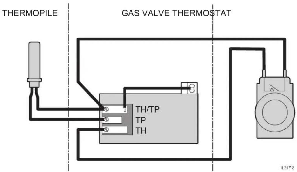
WIRING DIAGRAM
text_image
THERMOPILE GAS VALVE THERMOSTAT TH/TP TP TH IL2192NOTE: Shown is the wiring diagram for a single burner section. Each burner section is wired identically.
EXPLODED VIEW & PARTS LIST
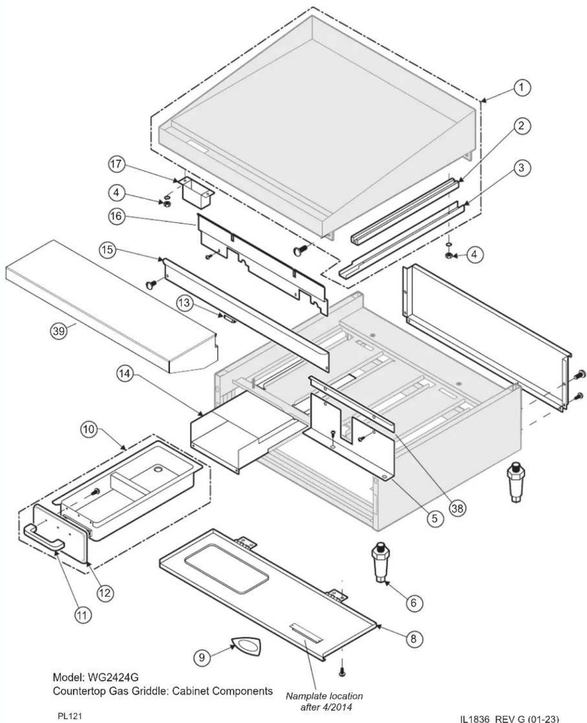
WG2424G CABINET COMPONENTS
text_image
1 2 3 4 5 6 7 8 9 10 11 12 13 14 15 16 17 18 19 20 21 22 23 24 25 26 27 28 29 30 31 32 33 34 35 36 37 38 39 Model: WG2424G Countertop Gas Griddle: Cabinet Components PL121 Namplate location after 4/2014 IL1836 REV G (01-23)M121 p/n 2M-45324 Owners Manual Countertop Gas Griddles
EXPLODED VIEW & PARTS LIST
WG2424G FUEL SYSTEM COMPONENTS
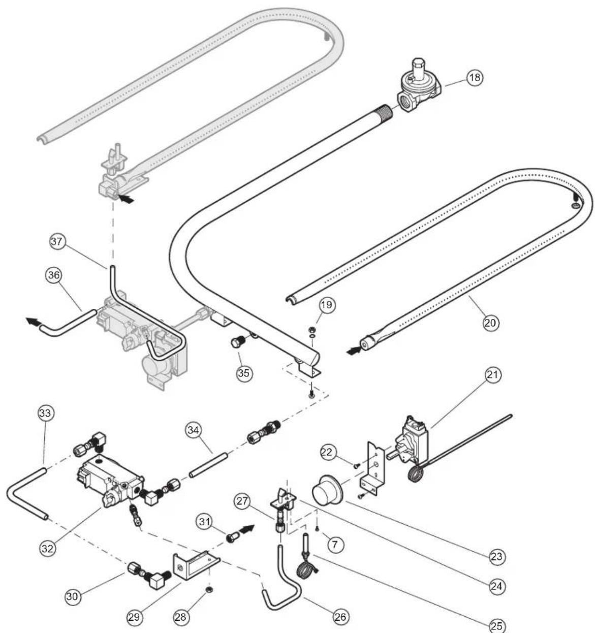
text_image
Exploded view diagram of a pressure regulator assembly with numbered parts for identificationModel: WG2424G
Countertop Gas Griddle: Fuel System Components
PL121
IL1837 Rev. D 4/13/12
PARTS LIST: WG2424
| Model: WG2424 Gas Griddle | ||||
| Fig No. Part Number Quantity Description Application | ||||
| 1 48527A 1 TOP ASSY WG2424 | ||||
| 2* 2H-39039 2 INSUL GAS THERMO BULB GAS | Models built before Nov. 2022 | |||
| 3* G7-45951 2 HOLDER THERMO BULB 24IN G | Models built before Nov. 2022 | |||
| 4 2C-3485 2 NUT 1/4-20 HEX FINISHED S | ||||
| 5 G7-45397 1 DEFLECT HEAT LOW WG2424G | ||||
| 6 2A-Z314 4 FOOT, 4" DIE CAST | ||||
| 7 2C-33922 30 SCREW 6-32X1/4 PH PAN TAP | ||||
| 8 G7-WL0596 | 1 PANEL CONTROL WG2424 | |||
| 9 2M-306719 | 1 LOGO WELLS DIECAST SHIELD | |||
| 10 | G7-302508 | 1 | DRAWER GREASE | WG2424GL |
| WS-59173 | DRAWER ASSY GREASE | |||
| 11 2R-38668 1 HANDLE DOOR | ||||
| 12 | G7-Z12047 | 1 PANEL FRONT - GREASE DRW | ||
| 13 | 2C-33453 1 CATCH DOOR MAGNETIC | |||
| 14 | G7-302521 | 1 INSERT GREASE DRAWER ASSY | ||
| 15 | G7-WL1070 | 1 PANEL FRONT WG2424 | ||
| 16 | G7-45274 1 DEFLECTOR HEAT FR WG2424 | |||
| 17 | G7-39331 1 CHUTE ASSY GREASE GAS GRI | |||
| 18 | 2J-39284 | 1 | REGULATOR ADJ GAS LP | |
| 2J-39007 | REGULATOR ADJ GAS NAT | |||
| 2J-306629 | RGLTR-GAS CONVRT 5/10 WC | LP or NAT | ||
| 19 | 2C-40680 2 NUT 10-32 HEX KEPS MS SS | |||
| 20 | 2F-45303 | 2 BURNER WG2424 2436 | ||
| 21 | 2T-48817 | 2 THERMO RX WG GRIDDLES | ||
| 22 | 2C-31718 2 SCREW 6-32X3/16 PH RD HD | |||
| 23 | 2R-45321 2 KNOB CONTROL WG2424-3048 | |||
| 24 | 2J-45308 | 2 PILOT WG GRIDL | ||
| 25 | 2T-42195 | 3 THERMOPILE FGS-40 | ||
| 26 | Pre 11/15/2019: 2A-45317Post 11/15/2019: 2A-Z22807 | 1 TUBE PILOT-2 | ||
| 27 | 2A-45352 | 2 ORIFICE PILOT PROPANE WG' | ||
| 28 | 2C-31053 2 NUT 8-32 KEPS MS NICKEL | |||
| 29 | G7-45281 2 SUPPORT ORIFICE ROHS | |||
| 30 | 2K-45357 | 2 FTG ORIFICE WG2424-3048 | ||
| 31 | 2J-Y7136 | 2 | ORIFICE-HOOD #53 (LP) | |
| 2A-45408 | ORIFICE-HOOD #42 (NAT) | |||
| 32 | Pre 11/15/2019: WS-65307Post 11/15/2019: WS-WL1000 | 2 VALVE GAS WG SERIES GRIDDLE | ||
| 33 | 2A-45315 | 1 TUBE BURNER-2 | ||
| 34 | 2A-45313 | 2 TUBE MANIFOLD | ||
| 35 | 2P-39245 | 1 PLUG HEX HEAD 1/8 NPT BRA | ||
| 36 | 2A-45314 | 1 TUBE BURNER-1 | ||
| 37 | Pre 11/15/2019: 2A-45318Post 11/15/2019: 2A-Z22808 | 1 TUBE PILOT-1 | ||
| 38 | G7-45398 1 DEFLECTOR HEAT UPPER | |||
| 39 | G7-Z18306 | 1 | SHELF PANEL, 24" GRIDDLE | 2424PS |
EXPLODED VIEW & PARTS LIST
WG2436G CABINET COMPONENTS
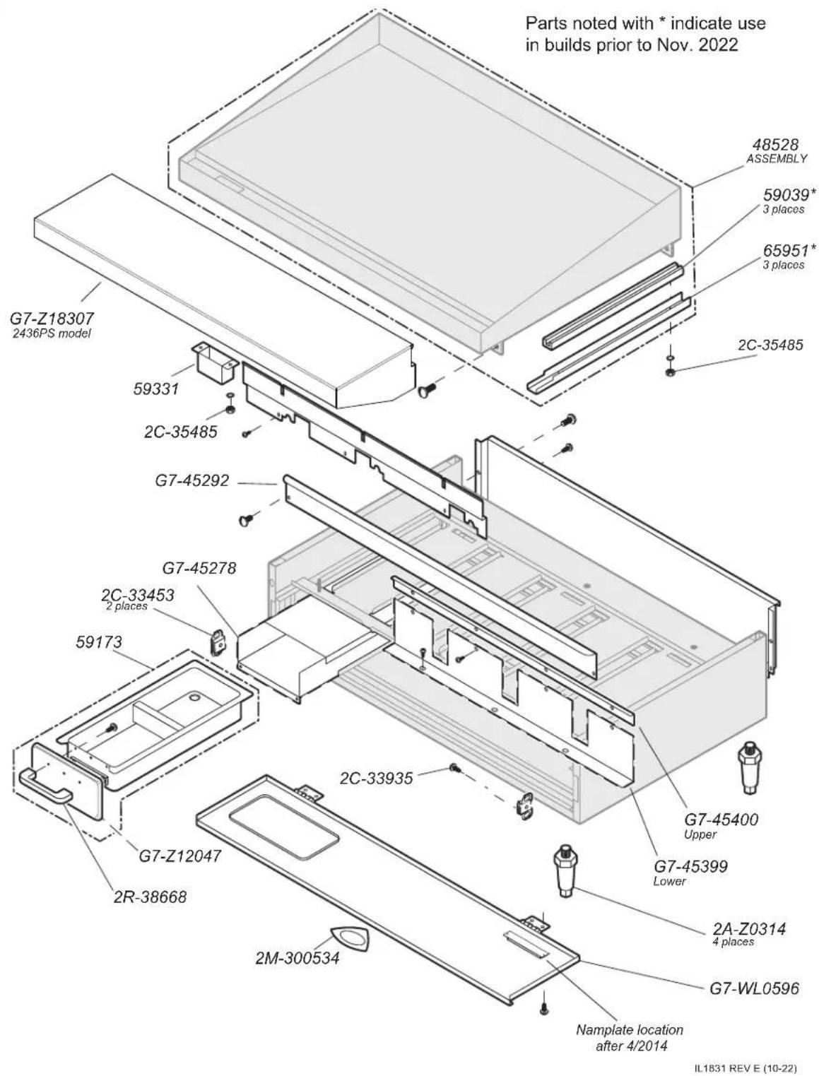
text_image
Parts noted with * indicate use in builds prior to Nov. 2022 48528 ASSEMBLY 59039* 3 places 65951* 3 places 2C-35485 G7-Z18307 2436PS model 59331 2C-35485 G7-45292 G7-45278 2C-33453 2 places 59173 G7-Z12047 2R-38668 2C-33935 2M-300534 G7-45400 Upper G7-45399 Lower 2A-Z0314 4 places G7-WL0596 Namplate location after 4/2014 IL1831 REV E (10-22)M121 p/n 2M-45324 Owners Manual Countertop Gas Griddles
EXPLODED VIEW & PARTS LIST
WG2436G FUEL SYSTEM COMPONENTS
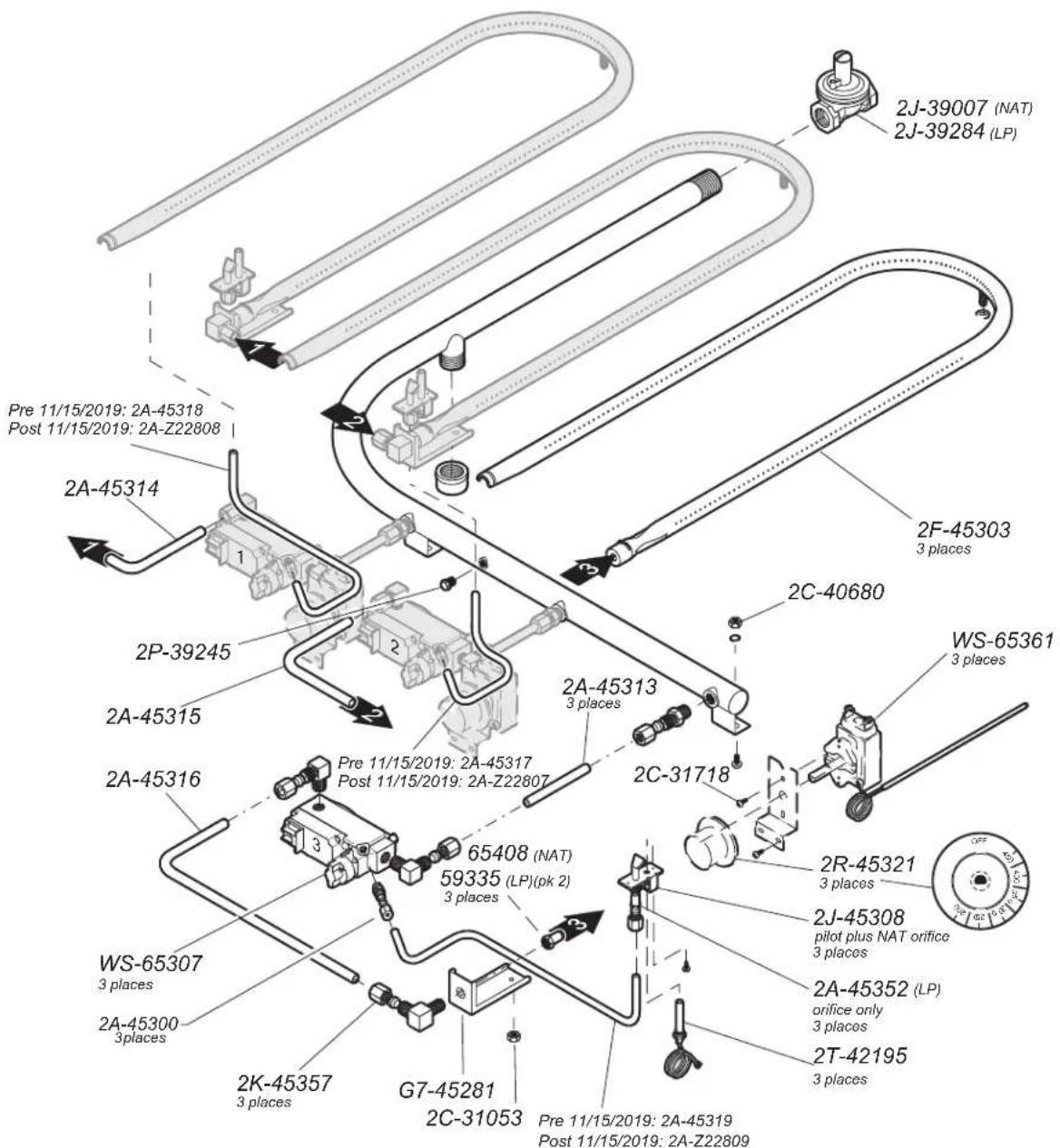
text_image
2J-39007 (NAT) 2J-39284 (LP) Pre 11/15/2019: 2A-45318 Post 11/15/2019: 2A-Z22808 2A-45314 2F-45303 3 places 2C-40680 2P-39245 2A-45315 2A-45316 Pre 11/15/2019: 2A-45317 Post 11/15/2019: 2A-Z22807 65408 (NAT) 59335 (LP)(pk 2) 3 places 2A-45313 3 places 2C-31718 WS-65361 3 places 2R-45321 3 places 2J-45308 pilot plus NAT orifice 3 places 2A-45352 (LP) orifice only 3 places 2T-42195 3 places 2K-45357 3 places G7-45281 2C-31053 Pre 11/15/2019: 2A-45319 Post 11/15/2019: 2A-Z22809Model: WG2436G
Countertop Gas Griddle: Fuel System Components
PL121
IL1832 Rev. D 9/20
EXPLODED VIEW & PARTS LIST
WG3036G CABINET COMPONENTS
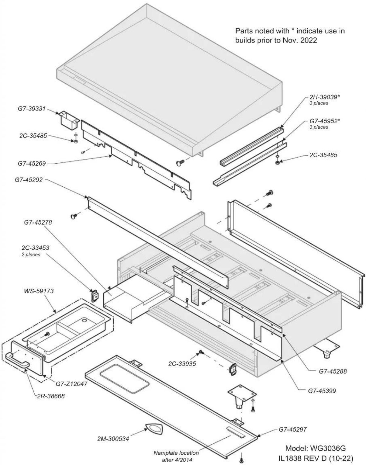
text_image
Parts noted with * indicate use in builds prior to Nov. 2022 G7-39331 2C-35485 G7-45269 G7-45292 G7-45278 2C-33453 2 places WS-59173 G7-Z12047 2R-38668 2C-33935 2M-300534 Namplate location after 4/2014 G7-45288 G7-45399 G7-45297 G7-45952* 3 places 2H-39039* 3 places 2C-35485 G7-45297 Model: WG3036G IL1838 REV D (10-22)M121 p/n 2M-45324 Owners Manual Countertop Gas Griddles
EXPLODED VIEW & PARTS LIST
WG3036G FUEL SYSTEM COMPONENTS

text_image
Adjustable REGULATOR 2J-39007 (NAT) 2J-39284 (LP) REGULATOR CONVERTIBLE FOR LP OR NAT 2J-306629 Pre 11/15/2019: 2A-45318 Post 11/15/2019: 2A-Z22808 2A-45314 2P-39245 2A-45315 Pre 11/15/2019: 2A-45317 Post 11/15/2019: 2A-Z22807 2A-45316 2A-45313 3 p laces 2C-40680 2F-45302 3 p laces WS-65361 3 p laces 2C-31718 2R-45321 3 p laces 2J-45308 pilot plus NAT orifice 3 p laces 2A-45352 (LP) orifice only 3 p laces 2T-42195 3 p laces 2A-45300 3 places WS-65307 3 places 2A-45319 Pre 11/15/2019: 2A-45319 Post 11/15/2019: 2A-Z22809 2K-45357 3 p laces G7-45281 2C-31053 Model: WG3036G Countertop Gas Griddle: Fuel System Components PL121 IL1839 Rev. D 9/20M121 p/n 2M-45324 Owners Manual Countertop Gas Griddles
EXPLODED VIEW & PARTS LIST
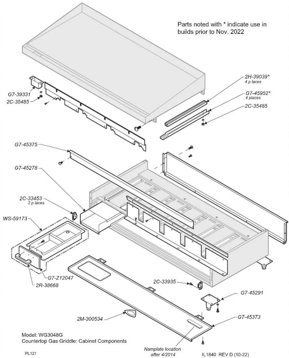
WG3048G CABINET COMPONENTS
text_image
Parts noted with * indicate use in builds prior to Nov. 2022 G7-39331 2C-35485 2H-39039* 4 p laces G7-45952* 4 places 2C-35485 G7-45375 G7-45278 2C-33453 2 p laces WS-59173 G7-Z12047 2R-38668 2C-33935 G7-45291 G7-45373 2M-300534 Model: WG3048G Countertop Gas Griddle: Cabinet Components PL121 Namplate location after 4/2014 IL1840 REV D (10-22)M121 p/n 2M-45324 Owners Manual Countertop Gas Griddles
EXPLODED VIEW & PARTS LIST
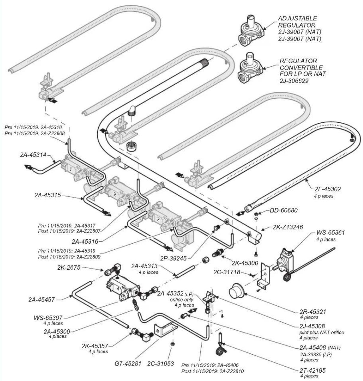
WG3048G FUEL SYSTEM COMPONENTS
text_image
ADJUSTABLE REGULATOR 2J-39007 (NAT) 2J-39007 (NAT) REGULATOR CONVERTIBLE FOR LP OR NAT 2J-306629 Pre 11/15/2019: 2A-45318 Pre 11/15/2019: 2A-Z22808 2A-45314 2A-45315 Pre 11/15/2019: 2A-45317 Post 11/15/2019: 2A-Z22807 2A-45316 Pre 11/15/2019: 2A-45319 Post 11/15/2019: 2A-Z22809 2A-45313 4 p laces 2P-39245 2K-2675 2A-45352 (LP) orifice only 4 p laces G7-45281 2C-31053 Pro 11/15/2019: 2A-45406 Post 11/15/2019: 2A-Z22810 2F-45302 4 p laces DD-60680 2K-Z13246 WS-65361 4 p laces 2K-45300 2C-31718 2R-45321 4 places 2J-45308 pilot plus NAT orifice 4 places 2A-45408 (NAT) 2A-39335 (LP) 4 places 2T-42195 4 placesModel: WG3048G
Countertop Gas Griddle: Fuel System Components
PL121
IL1841 Rev. E 9/20
NOTES
PARTS & SERVICE
DESCRIPTION
SERVICE PART NO.
LEGS, 4", METAL, SET OF 4 2A-Z0314
SCRAPER, GROOVED GRIDDLE 5G-20651
KIT, CONTROL PANEL ASSY WS-WL1057
IMPORTANT: Use only factory authorized service parts and replacement filters.
For factory authorized
service, or to order factory authorized replacement parts, contact your Wells authorized service agency, or call:
Wells Manufacturing 265 Hobson St.,
Smithville, TN 37166 USA
Service Dept.
phone: (800) 264-7827
Service Parts Department can supply you with the name and telephone number of the WELLS AUTHORIZED SERVICE AGENCY nearest you.
CUSTOMER SERVICE DATA
please have this information available if calling for service
RESTAURANT ____ LOCATION ____
INSTALLATION DATE ____ TECHNICIAN ____
SERVICE COMPANY
ADDRESS ____ STATE ____ ZIP ____
TELEPHONE NUMBER (____)____ - ____
EQUIPMENT MODEL NO. ____ EQUIPMENT SERIAL NO. ____
FUEL: (check one) _ Natural Gas _ Liquid Gas / Propane

text_image
WELLSWELLS MANUFACTURING
265 Hobson Street, Smithville, Tennessee 37166
telephone: 800-264-7827
www.wells-mfg.com
text_image
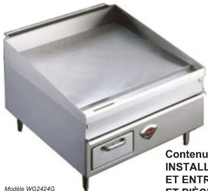
Modèle WG2424G Contenu INSTALL ET ENTR ET PIÈCMANUEL DE L'UTILISATEUR
natural_image
Silhouette of a person reading a book (no text or symbols visible)TABLE DES MATIÈRES
SPÉCIFICATIONS 1
CARACTÉRISTIQUES ET COMMANDES
DE FONCTIONNEMENT 2
PRÉCAUTIONS ET RENSEIGNEMENTS GÉNÉRAUX 3
INFORMATION RELATIVE AUX ORGANISMES
D'HOMOLOGATION 4
INSTALLATION 4
RÉGLAGE INITIAL 8
FONCTIONNEMENT 10
DIRECTIVES DE NETTOYAGE
CONFORMITÉ AU CODE DES APPAREILS ALIMENTÉS AU GAZ
1 Batterymarch Park P.O. Box 9101
Quincy, MA 02269-9101
INSTALLATION
DANGER: RISQUE D'INCENDIE ET D'EXPLOSION
Commercial Food Equipment Service Association
Wells proudly supports CFESA
Commercial Food Equipment Service Association
SERVICE TRAINING - QUALITY SERVICE

text_image
Genuine Paris Protect - YOU - All - WaysCUSTOMER SATISFACTION