AR24BVHGAWKAF - Air-conditioner SAMSUNG - Free user manual and instructions
Find the device manual for free AR24BVHGAWKAF SAMSUNG in PDF.
Download the instructions for your Air-conditioner in PDF format for free! Find your manual AR24BVHGAWKAF - SAMSUNG and take your electronic device back in hand. On this page are published all the documents necessary for the use of your device. AR24BVHGAWKAF by SAMSUNG.
USER MANUAL AR24BVHGAWKAF SAMSUNG
- Thank you for purchasing this Samsung air conditioner.
Pipe expanding method Configuration of connection pipe
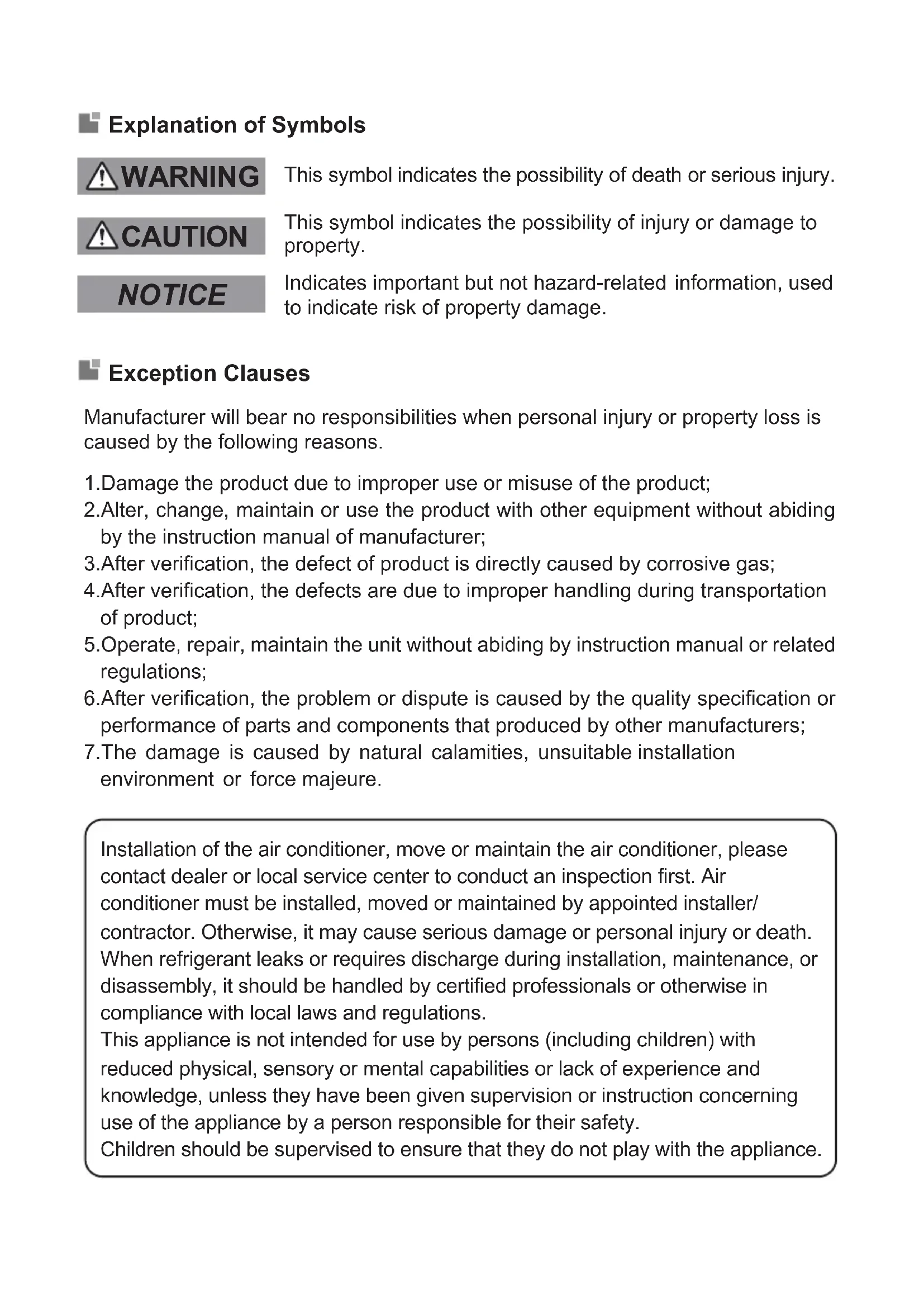
Tools for installation ............................................................................................13 Air switch capacity ...............................................................................................14Explanation of Symbols WARNING CAUTION NOTICE 1.Damage the product due to improper use or misuse of the product; 2.Alter, change, maintain or use the product with other equipment without abiding by the instruction manual of manufacturer; 3.After verification, the defect of product is directly caused by corrosive gas; 4.After verification, the defects are due to improper handling during transportation of product; 5.Operate, repair, maintain the unit without abiding by instruction manual or related regulations; 6.After verification, the problem or dispute is caused by the quality specification or performance of parts and components that produced by other manufacturers; 7.The damage is caused by natural calamities, unsuitable installation environment or force majeure. Exception Clauses Manufacturer will bear no responsibilities when personal injury or property loss is caused by the following reasons. This symbol indicates the possibility of death or serious injury. This symbol indicates the possibility of injury or damage to property. Indicates important but not hazard-related information, used to indicate risk of property damage. Installation of the air conditioner, move or maintain the air conditioner, please contact dealer or local service center to conduct an inspection first. Air conditioner must be installed, moved or maintained by appointed installer/ contractor. Otherwise, it may cause serious damage or personal injury or death. When refrigerant leaks or requires discharge during installation, maintenance, or disassembly, it should be handled by certified professionals or otherwise in compliance with local laws and regulations. This appliance is not intended for use by persons (including children) with reduced physical, sensory or mental capabilities or lack of experience and knowledge, unless they have been given supervision or instruction concerning use of the appliance by a person responsible for their safety. Children should be supervised to ensure that they do not play with the appliance.Safety precautions Installation
WARNING Installation or maintenance must be performed by qua- lified professionals. The appliance shall be in- stalled in accordance with national wiring regulations. According to the local safe- ty regulations, use quali- fied power supply circuit and circuit breaker. All wires of indoor unit and outdoor unit should be con- nected by a professional. Be sure to cut off the power supply before proceeding any work related to elec- tricity and safety. Make sure the power supp- ly matches with the require- ment of air conditioner. Unstable power supply or incorrect wiring may result in electric shock, fire haza- rd or malfunction. Please install proper power supply cables before using the air conditioner. The grounding resistance should comply with nation- al electric safety regula- tions. Air Conditioner should be properly grounded. Inco- rrect grounding may cause electric shock. Do not put through the power before finishing in- stallation. Do install the circuit brea- ker. If not, it may cause malfunction. An all-pole disconnection switch having a contact se- paration of at least 3mm in all poles should be conne- cted in fixed wiring. Circuit breaker should be included magnet buckle and heating buckle func- tion. It can protect the overload and circuit-short.Safety precautions Installation
CAUTION Instructions for installation and use of this product are provided by the manufac- turer. Select a location which is out of reach for children and far away from animals or plants. If it is unavoid- able, please add the fence for safety purpose. The indoor unit should be installed close to the wall. Don't use unqualified pow- er cord. If the length of power con- nection wire is insufficient, please contact the supplier for a new one. The appliance must be po- sitioned so that the plug is accessible. For the air conditioner with plug, the plug should be re- achable after finishing in- stallation. For the air conditioner with- out plug, a circuit breaker must be installed in the line. The yellow-green wire in air conditioner is ground- ing wire, which can't be us- ed for other purposes. The air conditioner is the first class electric applian- ce. It must be properly gro- under with specialized gr- ounding device by a pro- fessional. Please make sure it is always ground- ed effectively, otherwise it may cause electric shock. The temperature of refri- gerant circuit will be high, please keep the interconn- ection cable away from the copper tube.Safety precautions Operation and Maintenance
WARNING This appliance can be used by children aged from 8 years and above and per- sons with reduced physi- cal, sensory or mental ca- pabilities or lack of expe- rience and knowledge if they have been given su- pervision or instruction con- cerning use of the applian- ce in a safe way and un- derstand the hazards in- volved. Children shall not play with the appliance. Cleaning and user main- tenance shall not be made by children without super- vision. If the supply cord is damag- ed, it must be replaced by the manufacturer, its ser- vice agent or similarly qua- lified persons in order to avoid a hazard. Do not connect air condi- tioner to multi-purpose soc- ket. Otherwise, it may cau- se fire hazard. Do disconnect power supp- ly when cleaning air condi- tioner. Otherwise, it may cause electric shock. Do not wash the air condi- tioner with water to avoid electric shock. Do not spray water on in- door unit. It may cause ele- ctric shock or malfunction. Do not repair air condition- er by yourself. It may cause electric shock or damage. Please contact dealer when you need to repair air con- ditioner. After removing the filter, do not touch fins to avoid in- jury. Do not extend fingers or objects into air inlet or air outlet. It may cause person- al injury or damage.Safety precautions Operation and Maintenance
CAUTION Do not spill water on the re- mote controller, otherwise the remote controller may be broken. Do not use fire or hair dry- er to dry the filter to avoid deformation or fire hazard. Do not block air outlet or air inlet. It may cause mal- function. Do not step on top panel of outdoor unit, or put heavy objects. It may cause dam- age or personal injury. When below phenomenon occurs, please turn off air conditioner and disconnect power immediately, and then contact the dealer or qualified professionals for service. Power cord is overheat- ing or damaged. There’s abnormal sound during operation. Circuit breaker trips off frequently. Air conditioner gives off burning smell. Indoor unit is leaking.CAUTION
Correct disposal of batteries in this product This marking on the battery, manual or packaging indicates that the batteries in this product should not be disposed of with other household waste at the end of their working life. Where marked, the chemical symbols Hg, Cd or Pb indicate that the battery contains mercury, cadmium or lead above the reference levels in EC Directive 2006/66. Correct Disposal of This Product (Waste Electrical & Electronic Equipment) (Applicable in countries with separate collection systems) This marking on the product, accessories or literature indicates that the product and its electronic accessories (e.g. charger, headset, USB cable) should not be disposed of with other household waste at the end of their working life. To prevent possible harm to the environment or human health from uncontrolled waste disposal, please separate these items from other types of waste and recycle them responsibly to promote the sustainable reuse of material resources. Household users should contact either the retailer where they purchased this product, or their local government office, for details of where and how they can take these items for environmentally safe recycling. Business users should contact their supplier and check the terms and conditions of the purchase contract. This product and its electronic accessories should not be mixed with other commercial wastes for disposal. Safety precautions6
Parts name Indoor Unit Outdoor Unit Display NOTE
Actual product may be different from above graphics, please refer to actual product. This is the general introduction and the color of indicator is only for reference. Please refer to the actual display. Display content may be different from the actual. Please refer to the actual display. NOTE aux. buttonfilterair inlet panelhorizontal louverair outlet
If remote controller is lost or damaged, please use aux. button to turn on or turn off the air conditioner. The operation in details is as below: As shown in the figure, open panel and press aux. button to turn off the air conditioner. When the air conditioner is turned on, it will operate under auto mode. air inletair outlet heating indicator temp. indicator cooling indicator power indicator receiver window drying indicator display WARNING Use insulated object to press the auto buttonON/OFF MODE X-FANTURBO TEMP TIMER OFFSLEEPLIGHT FAN CLOCKTIMER ON Set temperature X-FAN function Set temp. temp. Outdoor ambient Indoor ambient temp. Sleep mode Clock Auto mode Set time
Introduction for icons on display screen Buttons on remote controller Operation and introduction of remote controller●
Press this button to select your required operation mode.
Introduction for buttons on remote controller Press this button to turn on the unit. Press this button again to turn off the unit.
ON/OFF FAN button Press this button can set fan speed circularly as: auto (AUTO), low ( ), medium ( ), high( ). button For preventing cold air, after starting up heat mode, indoor unit will delay the fan operation for 1~5 minutes (Actual delay time depends on indoor ambient temperature). Set temperature range from remote controller: 16~30℃(61-86℉). This mode indicator is not available for some models. Cooling only unit won't receive heat mode signal. If setting heat mode with remote controller, press ON/OFF button can't start up the unit. button When selecting heat mode, the air conditioner operates under heat mode. Press "+" or "-" button to adjust set temperature. Press "FAN" button to adjust fan speed. Press " " button to adjust fan blowing angle. Press this button can select up & down swing angle. Fan blow angle can be selected circularly as below: Under Auto speed, air conditioner will select proper fan speed automatically according to ambient tem- perature. Fan speed under dry mode is low speed. When selecting auto mode, air conditioner will operate automatically according to ambient tem- perature. Set temperature can't be adjusted and will not be displayed as well. Press "FAN" button can adjust fan speed. Press " " button can adjust fan blowing angle. When selecting cool mode, air conditioner will operate under cool mode. Press "+" or "-" button to adjust set temperature. Press "FAN" button to adjust fan speed. Press " " button to adjust fan blowing angle. When selecting dry mode, the air conditioner operates at low speed under dry mode. Under dry mode, fan speed can't be adjusted. Press " " button to adjust fan blowing angle. When selecting fan mode, the air conditioner will only blow fan, no cooling and no heating. Press "FAN" button to adjust fan speed. Press " " button to adjust fan blowing angle. NOTE NOTE NOTE This is a general use remote controller. It could be used for the air conditioner with multifunction. For the functions which the model doesn't have, if the corresponding button is pressed on the remote controller, the unit will keep the original running status. After putting through the power, the air conditioner will give out a sound. Power indicator " " is ON. After that, you can operate the air conditioner by using remote controller. Under on status, pressing the button on the remote controller, the signal icon " " on the display of remote controller will blink once and the air condition- er will give out a sound, which means the signal has been sent to the air conditioner. Press "+" or "-" button once increase or decrease set temperature 1℃(℉). Holding "+" or "-" button, 2s later, set temperature on remote controller will change quickly. On releasing button after setting is finished, temperature indicator on indoor unit will change accordingly. (Temperature can’ t be adjust- ed under auto mode) When setting TIMER ON, TIMER OFF or CLOCK, press "+" or "-" button to adjust time. (Refer to CLOCK, TIMER ON, TIMER OFF buttons).●
no display(horizontal louvers stops at current position)
" may not be available. When air condi- tioner receives this signal, the air conditioner will blow fan automatically.
TIMER ON button Press "TIMER ON" to confirm it. The word "ON" will stop blinking. " " icon resumes displaying. Cancel TIMER ON: Under the condition that TIMER ON is started up, press "TIMER ON" button to cancel it. TIMER OFF button "TIMER OFF" button can set the time for timer off. After pressing this button, " "icon disap- pears and the word "OFF" on remote controller blinks. Pr ess Press "+" or "-" button to adjust TIMER OFF setting. After each pressing "+" or "-" button, TIMER OFF setting will incr ease or decrease 1min. Holding "+" or "-" button, 2s later, the time will change quickly until reaching your required time. Press "TIMER OFF" and the word "OFF" will stop blinking. " " icon resumes displaying. Under the condition that TIMER OFF is started up, press "TIMER OFF" button to cancel it. Clock time adopts 24-hour mode. The in terval b etween two operations can 't exceed 5s. Otherwise, remote controller will quit setting status. Operation for TIMER ON/TIMER OFF is the same. button/ When selectin g " ", air conditioner is blowing air automatically. Horizontal louver will automat- ically swing up & down at maximum angle. When selecting 、 、 air condition- er is blowing air at fixed position. Horizontal louver will stop at the fixed position. When selecting "
", air conditioner is blowing air at fixed angle. Horizontal louver will send air at the fixed angle. Hold " "button above 2s to set your required swing angle. When reaching your required angle, release the button. Press this button to set clock time. " " icon on remote controller will blink. Press "+" or "-" button within 5s to set clock time. Each pressing of "+" or "-" button, clock time will increase or decrease 1 minute. If hold "+" or "-" button, 2s later, time will change quickly. Release this button when reaching your required time. Press "CLOCK" button to confirm the time. " " icon stops blinking. X-FANCLOCKTIMER ON Press this button under cool and dry mode to start up X-FAN function, and " " icon on remote control- ler will be displayed. Press this button again to cancel X-FAN function, and " " icon will disappear. TIMER OFF button TURBO When X-FAN function is on, if the air conditioner is turned off, indoor fan will still operate at low speed for a while to blow the residual water inside the air duct. During X-FAN operation, press X-FAN button to tur n off X-FAN function. Indoor fan will stop operation immediately. Under cool or heat mo de, press this button to turn to quick cool or quick h eat mode. " " icon is displayed on remote controller. Press this button
Under on and off status, you can set TIMER OFF or TIMER ON simultaneously. Before setting TIMER ON or TIMER OFF, please adjust the clock time. After starting up TIMER ON or TIMER OFF, set the constant circulating valid. After that, air conditioner will be turned on or turned off according to setting time. ON/OFF button has no effect on setting. If you don 't need this function, please use remote control- ler to cancel it. "TIMER ON" button can set the time for timer on. After pressing this button, " " icon disap- pears and the word "ON" on rem ote controller blinks. Press "+" or "-" button to adjust TIMER ON setting. After each pressing"+" or "-" button. TIMER ON setting will increase or decrease 1min. Holding "+" or "-" button, 2s later, the time will change quickly until reaching your required time. NOTE NOTE NOTE NOTE
ambient temperature on indoor unit's display. The setting on remote controller is selected circularly as below: Function introduction for button combination buttons Child lock function SLEEP Under OFF status, press "-" and "MODE" buttons simultaneously to switch temperature display between ℃ and ℉. Outdoor temperature display is not available for some models. At that time, indoor unit receives " " signal, while it displays indoor set temperature.
's defaulted to display set temperature when turning on the unit. There is no display in the remote control- ler. Only for the models whose indoor unit has dual-8 display. When selecting displaying of indoor or outdoor ambi- ent temperature, indoor temperature indicator displays corresponding temperature and automatical-ly turn to display set temperature after three or five seconds. button When selecting " " or no display with remote controller, temperature indicator on indoor unit displays set temperature. When selecting " " with remote controller, tem- perature indicator on indoor unit displays indoor ambient temperature. When selecting " " with remote controller, temperature indicator on indoor unit displays outdoor ambient temperature. " " icon is displayed. TEMP button By pressing this button, you can see indoor set tem- perature, indoor ambient temperature or outdoor LIGHT again to exit turbo function and " " icon will disappear. Press this button to turn off display light on indoor unit. " " icon on remote controller disappears. Press this button again to turn on display light. Under COOL or HEAT mode, press this button to start up sleep function. " " icon is displayed on remote controller. Press this button again to cancel sleep function and " " icon will disappear. Press "+" and "-" simultaneously to turn on or turn off child lock function. When child lock function is on, " " icon is displayed on remote controller. If you operate the remote controller, the " " icon will blink three times without sending signa l to the unit. NOTE Auto clean function
NOTE The auto clean function can only work under norm ambient temperature. If the room is dusty, clean air conditioner once a month; if not, clean air conditioner once every three months. After the auto clean function is turned on, you can leave the room. When auto clean is finished, the air conditioner will enter standby status. This function is only available for some models. Under unit off status, hold "MODE" and "FAN" buttons simultaneously for 5s to turn on or turn off the auto clean function. When the auto clean func- tion is turned on, indoor unit displays "CL". During the auto clean process of evaporator, the unit will perform fast cooling or fast heating. There may be some noise, which is the sound of flowing liquid or thermal expansion or cold shrinkage. The air con- ditioner may blow cool or warm air, which is a normal phenomenon. During cleaning process, please make sure the room is well ventilated to avoid affecting the comfort. 10Cleaning and maintenance
NOTICE: Checking after use-season Check whether air inlets and air outlets are bl- Do not remove the panel when c leaning it. Error Code
Open panel Pull out the panel to a certain angle as shown in the fig. NOTICE
Remove filter Remove the filter as indicated in the fig. NOTICE: Checking before use-season Notice for recovery
Install filter Install the filter and then close the panel cover tightly. If there're other error codes, please contact qu-alified professionals for service. Disconnect power supply. ocked. Check whether air switch, plug and socket are Clean filter and indoor unit’s panel. Clean surface of indoor unit When the surface of indoor unit is dirty, it is recomm- ended to use a soft dry cloth or wet cloth to wipe it. Many packing materials are recyclable mate-
Check whether drainage pipe is damaged. Check whether mounting bracke t for outdo
unit is damaged or corroded. If yes, please contact dealer. in good condition. 3.Check whether filter is clean. Check whether mounting bracket for outdoor unit is damaged or corroded . If yes, please contact dealer. The filter should be cleaned every three months . If there is much dust in the operation environme- nt, clean frequency can be increased. After removing the filter, do not touch fins to avoid injury. Do not use fire or hair dryer to dry the filter to avoid deformation or fire hazard. When air conditioner status is abnor mal, tempe- rature indicator on indoor uni t will blink to display corresponding error code. Please refer to below list for identification of error code. e tairporppa ni meht esopsid esaelP .slair recycling unit. esaelp , renoitidnoc ria eht esopsid ot tnaw uoy fI contact local dealer or consultant service center for the correct disposal method. Clean filter Use dust catcher or water to clean the filter. When the filter is very dirty, use the water (below 45℃) to clean it , and then put it in a shady and cool place to dry. Turn off the air conditioner and disconnect the power before cleaning the air conditioner to av- oid electric shock.
Do not wash the air conditioner with water to avoid el ectric shock.
Do not use volatile liquid to clean the air conditioner. Do not use liquid or corrosive detergent to clean the appliance and do not splash water or other liquid onto it , otherwise, it may damage the plastic components , and cause electric shock. , , ,, , ,, , , 11Checked items before maintenance Phenomenon SolutionEliminate the odour source. Clean the filter.Temperature can’t be adjusted under auto mode. Please switch the operationmode if you need to adjust temperature. Unit is operating un-der auto mode? Your required temp-erature exceeds theset temperature range? Whether remote co-ntroller is within the signal receiving range? Voltage is too low?Wait until the voltage resumes normal.Remove obstacles. Select proper angle and point the remote controller at the rece-iving window on indoor unit.Filter is dirty? Clean the filter.Whether remote co-ntroller is pointing at the receiving window?Adjust temperature toproper range. Is sensitivity of rem-ote controller low; fuzzy display or no display? Check the batteries. If th e powe r of batteriesis to o low , please rep-lace them. Whether there’s inte-rference, such as thunder, wireless devices, etc.Disconnect power, put back power, and then turn on the unit again.No display when op-erating remote cont-roller?Check whether rem-ote controller appearsto be damaged. If yes,replace it. During defrostingunder heating mode, it may generate vapor, which is a normal phenomenon.Take the remote con-troller close to indoorunit. Turn off the fluo-rescent lamp and thentry it again. The noise is the sound of refrigerant flowing inside the unit, which is a normal phenomenon. Eliminate obstacles.This is the sound of friction caused by expansion and
contraction of panel or other parts due tothe changeof temp-erature.Under heating mode, indoor temperature is reached to set temp-erature?In order to prevent blowing out cold air, indoor unit will be started after delaying for several minutes, which is a normal phenomenon.Heating mode is turned on just now? WARNING When below phenomenon occurs,please turn off air conditioner and disconnect power immedi- ately, and then contact the dealer or qualified professionals for service.
Power failure?Is plug loose?Reinsert the plug. ● Power cord is overheating or damaged. There’s abnormal sound during operation. Air switch trips off frequently. Air conditioner gives off burning smell. Indoor unit is leaking. Air switch trips off or fuse is burnt out? Ask professional to replace air switch or fuse. Wiring has malfunc-tion?Ask professional to replace it. Unit has restarted immediately after stopping operation? Wait for 3min, and then turn on the unit again. Do not repair or refit the air conditioner by yourself. If the air conditioner operates under abnormal conditions, it may cause malfunction, electric shock or fire hazard. Whether the function setting for remotecontroller is correct? Reset the function.Because indoor air is cooled rapidly. After a while, indoor temperature and hu- midity will be decrease and mist will disappe ar. Indoor temperature and humidity is high? Check itemsWhether there’s od-our source, such asfurniture and cigare-tte, etc. General phenomenon analysis Pleas e che ck be low it ems before asking for maintenance. If the malfunction still can’t be eliminated, please contact local dealer or qualified professionals. Phenomenon Odours are emittedCheck items Whether it's interfered severely (such as sta-tic electricity, stable voltage?) SolutionPull out the plug. Reinsert the plug after about 3min, and thenturn on the unit again. Set tempe-rature can’tbe adjusted Set temperature range: 16℃~30℃.Signal receiving range is 8m. Whether there are obstacles? Indoor unit can’t receive remote co-ntroller’s si-gnal or remote controller has no action.Cooling(heating)effect is not good. Set temperature is in proper range? Door and window are open? Close door and window.Air conditi- oner operates abnormallyOutdoor unit has vaporHeating mode is turned on? Fluorescent lamp in room? “Water flowing”noiseAir conditioner is turned on or turned off just now? Air inlet or air outlet of indoor unit is blocked? After reaching to settemperature,indoor unit will stop blowingout air. No air emitted from indoor unit Crackingnoise Air conditioner is turned on or turned off just now?Wait until power recovery.Air conditioner can’t operate
Mist is emi-tted fromindoor unit’sair outlet
To ensure safety, please be mindful of the following precautions.
WARNINGScrew driverImpact drillOpen-end Pipe cutter wrenchdetectorVacuum pumpLeakage Pressure meterLevel meter Please contact the local agent for installation. Don’t use unqualified power cold. tape Measuring meterUniversal spanner Inner hexagon When installing the unit, make sure that co- nnection pipe is securely connected before the compressor starts running. If compressor starts running when stop valve is open and connection pipe is not yet conne- cted, air will be sucked in and cause pressure rise or compressor rupture, resulting in injury. Drill bitNOTICEElectric wires with insufficient capacity, wrong wire connections and insecure wire terminals may cause electric shock or fire.
Pipe expander Torque wrench When installing or relocating the unit, be s- ure to keep the refrigerant circuit free from air or substances other than the specified refrigerant. Any presence of air or other foreign substance in the refrigerant circuit will cause system pre- ssure rise or compressor rupture, resulting in injury. When in stalling or moving the unit, do not charge the refrigerant which does not comply with that on the name plate of the air conditioner. Otherwise, it may cause abnormal operation, wrong action, mechanical malfunction or even serious safety accident. When refrigerant needs to be recovered during relocating or repairing the unit, be 1 minute. sure that the unit is running in cooling mode. Then, fully close the valve at high pressure side (liquid valve). About 30-40 seconds later, fully close the valve at low pressure side (gas valve), immediately stop the unit and disconnect power. Please note that the time for refrigerant recovery should not exceed Tools for installation
Drainage pipe Safety precautions for installing and relocating the unit Use the specified types of wires for electrical connections between the indoor and outdoor units. Firmly clamp the wires so that their te- rminals receive no external stresses. At least 15cm
At least 250cm Spac e ceilinge to th t least 15cm Space to the wall At least 15cm Space to the wall At least 300cmSpace to the obstructionSpace to the floor If refrigerant recovery takes too much time, air may be sucked in and cause pressure rise or compressor rupture, resulting in injury. During refrigerant recovery, make sure that liquid valve and gas valve are fully closed and power is disconnected before detachi- ng the connection pipe. If compressor starts running when stop valve is open and connection pipe is not yet conn- ected, air will be sucked in and cause pressure rise or compressor rupture, resulting in injury. Prohibit installing the unit at the place where there may be leaked corrosive gas or flamm- able gas. If there is leaked gas around the unit, it may cause explosion and other accidents. Do not use extension cords for electrical co- nnections. If the electric wire is not long eno- ugh, please contact a local service center au- thorized and ask for a proper electric wire. Poor connections may lead to electric shock or fire. WARNING Space to the obstructionAt least 50cmSpace to the obstructionAt least 30cm50cmAt least Space to the obs ructionSpace to the obstructionAt least 200cmSpace to the wallAt least 30cm14
Select a location where the condensation water
Selection of installation location
Requirements for electrical connection Air switch capacity Indoor unit
Basic requirement Installing the unit in the following places may cau-se malfunction. If it is unavoidable, please consu-lt the local dealer:
can be dispersed easily and won't affect otherpeople. Safety precaution
Select a location which is out of reach for chil-dren and far away from animals or plants. If itis unavoidable, please add the fence for safetypurpose.
It’s not allowed to be installed on the unstableor motive base structure (such as truck) or in the corrosive environment (such as chemicalfactory).
Select a location which is convenient to conne-ct the outdoor unit and near the power socket. Grounding requirement Do not put through the power before finishing Make sure that the installation follows the req-uirement of installation dimension diagram.There should be no obstruction near air inletand air outlet. 4.Select a location which is out of reach for children. Must follow the electric safety regulations w- hen installing the unit. air emitted by the outdoor unit will not affectneighborhood.installation. If the supply cord is damaged, it must be repla-The location should be well ventilated and dry,in which the outdoor unit won't be exposed dir-ectly to sunlight or strong wind.The location should be able to withstand theweight of outdoor unit. According to the local safety regulations, use Outdoor unit 1.Select a location where the noise and outflowqualified power supply circuit and air switch. 8.Please try your best to keep way from fluores-cent lamp.The yellow-green wire in air conditioner isgrounding wire, which can't be used for otherpurposes.An all-pole disconnection switch having a co-ntact separation of at least 3mm in all polesshould be connected in fixed wiring.The grounding resistance should comply withweight of indoor unit and won't increase noiseand vibration.The appliance must be installed 2.5m above floor.Don't install the indoor unit right above the ele-ctric appliance. The place with sulfureted gas.Other places with special circumstances.The appliance shall not be installed in theThe place with strong heat sources, vapors,flammable or explosive gas, or volatile objectsspread in the air.The place with high-frequency devices (suchas welding machine, medical equipment).The place near coastal area.The place with oil or fumes in the air.with national wiring regulations. The temperature of refrigerant circuit will be hi-4.Properly connect the live wire, neutral wire andfrom the copper tube. The appliance shall be installed in accordance
he air conditioner is the first class electric
appliance. It must be properly grounded with specialized grounding device by a professional.Please make sure it is always grounded effecti-vely, otherwise it may cause electric shock.ced by the manufacturer, its service agent orsimilarly qualified persons in order to avoid ahazard .national electric safety regulations.The appliance must be positioned so tha t the
g is accessible.The location should be able to withstand t heMake sure the power supply matches with therequirement of air conditioner. Unstable power supply or incorrect wiring or malfunction. Pl- ease install proper power supply cables before using the air conditioner.gh, please keep the interconnection cable awaygrounding wire of power socket. Be sure to cut off the power supply before pr-oceeding any work related to electricity and safety.Including an air switch with suitable capacity,please note the following table . Air switch sh-ould be included magnet buckle and heatingbuckle function, it can protect the circuit-shortand overload. (Caution: please do no t use thefuse only for protecting the circuit)Air-conditionerAir switch capacity 09K、12K 10A 18K 16A 24K 25AAccessories 15Indoor outdoor 5-10
pipe joint union nut pipe
Φ55 Install wall-mounting frame Step 2: Φ70 Outlet pipe Choose installation location Step 1: Recommend the installation location to the client and then confirm it with the client. right Step 4:
Hang the wall-mounting frame on the wall; adjust it in horizontal position with the level meter and then point out the screw fixing holes on the wall. Drill the screw fixing holes on the wall with im- pact drill(the specification of drill bit should be the same as the plastic expansion particle) and then fill the plastic expansion particles in the holes. Fix the wall-mounting frame on the wall with tapping screws and then check if the frame is firmly installed by pulling the frame. If the plastic expansion particle is loose, please drill another fixing hole nearby. Step 3: Open piping hole
Step 5: Connect the pipe of indoor unit Installation of indoor unit
wall-mounted frame, shown as below. Aim the pipe joint at the corresponding NOTE left right left rear right, left or rear left. Pay attention to dust prevention -aem ytefas tnav eler ekat dnasures when opening the hole. bellmouth. Pretighten the union nut with hand. Please refer to the actual circumstances for thenumber of screws and the position of screws. rear right
The pipe can be led out in the direction of right, Choose the position of piping hole according Adjust the torque force by referring to the wrench on the union nut. Tighten the union nut with torque wrench. When installation is finished, pull the mounting plate with hand to confirm whether it is fixed tightly. The force distribution for all screws should be uniform. Open a piping hole with the diameter of Φ55 or Φ70 on the selected outlet pipe position. In order to drain smoothly, slan t the piping hole on the wall slightly downward to the outdoor side with the gradient of 5-10°. to the direction of outlet pipe. The position of piping hole should be a little lower than the When select leading out the pipe from left or right, please cut off the corresponding hole on the bottom case. The wall panel is for illustrative purposes only,please refer to the actual installation. union nut torque wrench pipe indoor pipe open-end wrench following sheet. Place the open-end wren- ch on the pipe joint and place the torque Wall Wall (Rear piping hole) (For some models) (Rear piping hole) Space to the wall above 150mm Left Space to the wall above 150mm Right Mark in the middle of it Level meter 16● The plastic expansion particles are not provided. 4.All wires of indoor unit and outdoor unit should be If the length of power connection wire is insufficient,Add insulating pipe in the indoor drain hose in order to prevent condensation. For the air conditioner with plug, the plug should be panel1. drain hose
outlet pipe tape NOTE NOTICE Step 7: Connect wire of indoor unit connected by a professional.please contact the supplier for a new one. Avoid e-xtending the wire by yourself.reachable after finishing installation.For the air conditioner without plug, an air switchmust be installed in the line. The air switch shouldbe all-pole parting and the contact parting distanceshould be more than 3mm.screwwiring covercable-cross hole power connection wire Step 6: Install drain hose 1.Bind the joint with tape. indoor unit.Wrap the indoor pipe and joint of connectionpipe with insulating pipe, and then wrap itwith tape.insulating pipeinsulating pipedrain hose Open the panel, remove the screw on the wiring cover and then take down the cover.Connect the drain hose to the outlet pipe ofoutlet pipe drain hose Make the power connection wire go through the cable-cross hole at the back of indoor unit and then pull it out from the front side. Hex nut diameter 1/4'' 15~20 3/8'' 30~40 1/2'' 45~55 5/8'' 60~65 3/4'' 70~75 Tightening torque (N
upper hookindoor unit band NOTICE lower hook ofwall-mounting frameThe power cord and control wire can't be crossed orwinding. The drain hose should be bound at the bottom. indoor wall pipe
NOTICE outdoor Step 9: Hang the indoor unit
pipe liquid pipe Step 8: Bind up pipe drain hose indoor andoutdoor power cord NOTICE The wiring board is for reference only, please referto the actual one.Do not bend the drain hose too excessively in orderto prevent blocking.connection pipedrain hose band indoor power cord drain hose with the band. Put the bound pipes in the wall pipe and then Bind up the connection pipe, power cord and Bind them evenly. The liquid pipe and gas pipe should be bo- make them pass through the wall hole. Hang the indoor unit on the wall-mounting frame. Stuff the gap between pipes and wall hole with sealing gum. Fix the wall pipe. Check if the indoor unit is installed firmly and closed to the wall. und separately at the end. Remove the wire clip; connect the power conn- ection wire to the wiring terminal according to the color; tighten the screw and then fix the po- wer connection wire with wire clip. Put wiring cover back and then tighten the screw. Close the panel. green Outdoor unit connection N(1) 2 3 blue black brown yellow- Reserve a certain length of drain hose and power cord for installation when binding th- em. When binding to a certain degree, sep- arate the indoor power and then separate the drain hose. 18Place the outdoor unit on the support.
2. Fix the foot holes of outdoor unit with bolts.
foot holesfoot holes
1. Remove the screw on the right handle of out-
(select it according to the actual inst- Step 1: Fix the support of outdoor unit
gas valveliquid pipegas pipeliquidvalve Step 4: Connect indoor and outdoor pipes allation situation) door unit and then remove the handle.
union nutpipe joint Step 3: Fix outdoor unit NOTICE
Installation of outdoor unit Step 2: Install drain joint (only for some models)
1. Connect the outdoor drain joint into the hole
NOTICE Select installation location according to the house structure. Fix the support of outdoor unit on the sele- cted location with expansion screws. on the chassis, as shown in the picture below. Connect the drain hose into the drain vent. NOTE cross-holeAs for the shape of drainage joint, please refer to the current product. Do not install the drainage joint in the severe cold area. Otherwise,it will be frosted and then cause malfunction.
2. Remove the screw cap of valve and aim the
pipe joint at the bellmouth of pipe.
When there're multiple cables passing through it, the cross-hole of handle should be knocked off and eliminate the sharp burrs for avoid damaging the cables. Only applicable for some models. Pretighten the union nut with hand. Take sufficient protective measures when installin g the outdoor unit. Make sure the support can withstand at least fou r times of the unit weight.The outdoor unit should be installed at least 3cm above the floor in order to install drain joint. (for the model with heating tube, the installation height should be no less than 20cm.)For the unit with cooling capacity of 2300W
5000W, 6 expansion screws are needed ; for the unit with cooling capacity of 6000W~8000W, 8 expansion screws are needed; for the unit with cooling capacity of 10000W~16000W, 10 expansion screws are needed. handlescrewdrain ventDrain hosechassisoutdoor drain jointat least 3cm above the floor
1. Remove the wire clip; connect the power con-
wall The drain hose can't be curved, raised The water outlet can't be placed in water in order to drain smoothly.
1/4'' 3/8'' 1/2'' 5/8'' 3/4'' 15~20 30~40 45~55 60~65 70~75 Connect outdoor electric wire Step 5: the drain hosecan't raiseupwards.The water outlet can't be placed Slant the drain hose slightly downwards. The drain hose can't be curved, raised and fluctuant, etc. in water nection wire and signal control wire (only for cooling and heating unit) to the wiring terminal according to the color; fix them with screws. The drain hosecan't be curved, raisedThe water outlet can't becurved, raised Fix the power connection wire and signal con- trol wire with wire clip (only for cooling and h- eating unit). Step 6: Neaten the pipes
U-shaped curve drain hose NOTICE NOTICE NOTICE Tighten the union nut with torque wrench by referring to the sheet below. The wiring board is for reference only, please referto the actual one. The pipes should be placed along the wall, bent If the outdoor unit is higher than the wall hole, reasonably and hidden possibly. Min. semidiam- eter of bending the pipe is 10cm. After tighten the screw, pull the power cord slightlyto check if it is firm. Never cut the power connection wire to prolong orshorten the distance. The through-wal height of drain hose shoul not be higher than the outlet pipe hole of in- door unit. you must set a U-shaped curve in the pipe before pipe goes into the room, in order to prevent rain from getting into the room. Indoor unit connection N(1) 2 3 blue black brownyellow-green 20Test operation Test and operation
Preparation of test operation The client approves the air conditioner. Specify the important notes for air conditioner to the client.
Leakage detection Use vacuum pump Tighten the screw caps of valves and refriger-
Reinstall the handle.7. tus for 1-2min to check if the pressure of piezo- meter remains in -0.1MPa. If the pressure de- creases, there may be leakage. Remove the piezometer, open the valve core of liquid valve and gas valve completely with inner hexagon spanner. piezometervalve capliquid valveLo Higas valverefrigerant charging vent nut of refrigerantcharging ventclose open vacuum pumpinner hexagonspanner for 10-15min to check if the pressure of piezo- meter remains in -0.1MPa.
4. Close the vacuum pump and maintain this sta-
Open the piezometer completely and operate Remove the valve caps on the liquid valve and refrigerant charging vent of gas valve and then connect the other charging hose to the vacuum pump. With leakage detector: Check if there is leakage with leakage detector. With soap water: If leakage detector is not available, please use soap water for leakage detection. Apply soap water at the suspected position and keep the soap water for more than 3min. If there are air bubbles coming out of this position, there's a leakage. gas valve and the nut of refrigerant charging vent. Check after installation ● Check according to the following requirement after finishing installation. Possible malfunction The unit may drop, shake oremit noise. Connect the charging hose of piezometer to the Is water drained well?It may cause condensation and water dripping. Items to be checked Has the unit been installed firmly?Have you done the refri-gerant leakage test? It may cause malfunction or damage the parts. Is electric wiring and pip-eline installed correctly?It may cause malfunction or damage the parts. Is the unit grounded securely?Does the power cord fol-low the specification?It may cause malfunction or damage the parts. Is there any obstruction in the air inlet and outlet? It may cause insufficient cooling(heating) capacity.It may cause malfunction or damage the parts. The gas valve and liquid valve of connection pipe are open completely? The dust and sundries caused during installation are removed? Is heat insulation of pipe-line sufficient?It may cause condensation and water dripping. It may cause electric leakage.Is the inlet and outlet of piping hole been covered? Is the voltage of power supply according to the voltage marked on the nameplate?It may cause insufficient cooling(heating) capacity.It may cause insufficient cooling (heating) capacity.It may cause insufficient cooling (heating) capacity or waste electricity. Method of test operation Put through the power, pres s " ON/OFF " button on the remote controller to start operation. Press MODE button to select AUTO, COOL, DRY , FAN and HEAT to check whether the operation i s normal or not. If the ambient temperature is lower than 16℃, th e air conditioner can’t start cooling.
Max. length of connection pipe(m)
leaning uneven burr Configuration of connection pipe Standard length of connection pipe: 5m, 7.5m,
The additional refrigerant oil and refrigerant charg- ing required after prolonging connection pipe. 8m. Min. length of connection pipe is 3m. Max. length of connection pipe is shown as below. After the length of connection pipe is prolonged for 10m at the basis of standard length, you should add 5ml of refrigerant oil for each additional 5m of connection pipe. The calculation method of additional refrigerant charging amount(on the basis of liquid pipe): Additional refrigerant charging amount = prolonged length of liquid pipe × additional refrigerant charging amount per meter Confirm the pipe length according to the distance of indoor unit and outdoor unit. Cut the required pipe with pipe cutter. Basing on the length of standard pipe, add re- frigerant according to the requirement as shown in the table. The additional refrigerant charging amount per meter is different according to the diameter of liquid pipe. See the following sheet.
Additional refrigerant charging amount for R22, R407C, R410A and R134a
NOTICE Improper pipe expanding is the main cause of refriger- ant leakage. Please expand the pipe according to the following steps:
Piping size Liquid pipe heating(g/m) 1/4'' Outdoor unit throttle Cooling only(g/m) Cooling and
1/4'' or 3/8''1/2''5/8''3/4''7/8''burrs from getting into the pipe. pipe and outdoor valve; install the union nut on the pipe. Remove the burrs with shaper and prevent the the length is equal Working temperature range union pipe pipe
Remove the union nut on the indoor connection C: Put on suitable insulating pipe Expand the port with expander. smooth surfaceimproper expandinguneventhicknessleaningdamagedcracksurface Check the quality of expanding port. If there is expander pipe hard mold NOTICE
B: Remove the burrs D: Put on the union nut
F: Inspection any blemish, expand the port again according to the steps above. shaperdownwards pipe A(mm) Max Min Φ6 - 6.35(1/4")
Outer diameter (mm) "A" is different according to the diameter, please refer to the sheet below: 32/23 48/26 27/- 24/18 The operating temperature range (outdoor tem - DB/WB(°C) Indoor side DB/WB(°C) Outdoor side Maximum cooling Maximum NOTE
perature) for cooling only unit is 18
;for heat pump unit is -7
heating 32/23 43/26 27/- 24/18 The operating temperature range (outdoor tem - DB/WB(°C) Indoor side DB/WB(°C) Outdoor side Maximum cooling Maximum NOTE
perature) for cooling only unit is 18
;for heat pump unit is -7
Ce symbole indique la possibilité de blessures ou de dommages matériels. REMARQUE Indique des informations importantes mais non liées au danger, utilisées pour indiquer le risque de dommages matériels.1 Installation or maintenance must be performed by qua- lified professionals. The appliance shall be in- stalled in accordance with national wiring regulations. According to the local safe- ty regulations, use quali- fied power supply circuit and circuit breaker. All wires of indoor unit and outdoor unit should be con- nected by a professional. Be sure to cut off the power supply before proceeding any work related to elec- tricity and safety. Make sure the power supp- ly matches with the require- ment of air conditioner. Unstable power supply or incorrect wiring may result in electric shock, fire haza- rd or malfunction. Please install proper power supply cables befor e using the air conditioner. The grounding resistance should comply with nation- al electric safety regula- tions. Air Conditioner should be properly grounded. Inco- rrect grounding may cause electric shock. Do not put through the power before finishing in- stallation. Do install the circuit brea- ker. If not, it may cause malfunction. An all-pole disconnection switch having a contact se- paration of at least 3mm in all poles should be conne- cted in fixed wiring. Circuit breaker should be included magnet buckle and heating buckle func- tion. It can protect the overload and circuit-short. Précautions de sécurité Installation AVERTISSEMENT
- Ne mettez pas l'appareil sous tension avant de terminer l'installation.Instructions for installation and use of this product are provided by the manufac- turer. Select a location which is out of reach for children and far away from animals or plants. If it is unavoid- able, please add the fence for safety purpose. The indoor unit should be installed close to the wall. Don't use unqualified pow- er cord. If the length of power con- nection wire is insufficient, please contact the supplier for a new one. The appliance must be po- sitioned so that the plug is accessible. For the air conditioner with plug, the plug should be re- achable after finishing in- stallation. For the air conditioner with- out plug, a circuit breaker must be installed in the line. The yellow-green wire in air condit ioner is ground- ing wire, which can't be us- ed for other purposes. The air conditioner is the first class electric applian- ce. It must be properly gro- under with specialized gr- ounding device by a pro- fessional. Please make sure it is always ground- ed effectively, otherwise it may cause electric shock. The temperature of refri- gerant circuit will be high, please keep the interconn- ection cable away from the copper tube. Précautions de sécurité Installation
- La température du circuit de réfrigérant sera élevée, veuillez éloigner le câble d'interconnexion du tube de cuivre.This appliance can be used by children aged from 8 years and above and per- sons with reduced physi- cal, sensory or mental ca- pabilities or lack of expe- rience and knowledge if they have been given su- pervision or instruction con- cerning use of the applian- ce in a safe way and un- derstand the hazards in- volved. Children shall not play with the appliance. Cleaning and user main- tenance shall not be made by children without super- vision. If the supply cord is damag- ed, it must be replaced by the manufacturer, its ser- vice agent or similarly qua- lified persons in order to avoid a hazard. Do not connect air condi- tioner to multi-purpose soc-
et. O therwise, it may cau- se fire hazard. Do disconnect power supp- ly when cleaning air condi- tioner. Otherwise, it may cause electric shock. Do not wash the air condi- tioner with water to avoid electric shock. Do not spray water on in- door unit. It may cause ele- ctric shock or malfunction. Do not repair air condition- er by yourself. It may cause electric shock or damage. Please contact dealer when you need to repair air con- ditioner. After removing the filter, do not touch fins to avoid in- jury. Do not extend fingers or objects into air inlet or air outlet. It may cause person- al injury or damage. Précautions de sécurité Opération et Maintenance
Actual product may be different from above graphics, please refer to actual product. This is the general introduction and the color of indicator is only for reference. Please refer to the actual display. Display content may be different from the actual. Please refer to the actual display.
If remote controller is lost or damaged, please use aux. button to turn on or turn off the air conditioner. The operation in details is as below: As shown in the figure, open panel and press aux. button to turn off the air conditioner. When the air conditioner is turned on, it will operate under auto mode.
Press this button to turn on the unit. Press this button again to turn off the unit. When selecting auto mode, air conditioner will operate automatically according to ambient tem- perature. Set temperature can't be adjusted and will not be displayed as well. Press "FAN" button can adjust fan speed. Press " " button can adjust fan blowing angle. When selecting cool mode, air conditioner will operate under cool mode . Press "+" or "-" button to adjust set temperature. Press "FAN" button to adjust fan speed. Press " nottub " to adjust fan blowing angle. When selecting dry mode, the air conditioner operates at low speed under dry mode. Under dry mode, fan speed can't be adjusted. Press " " button to adjust fan blowing angle. When selecting fan mode, the air conditioner will only blow fan, no cooling and no heating. Press "FAN" button to adjust fan speed. Press " " button to adjust fan blowing angle. This is a general use remote controller. It could be used for the air conditioner with multifunction. For the functions which the model doesn't have, if press the corresponding b utton on the remote controller, the unit will keep the original running status. After putting through the power, the air conditioner will give out a sound. Power indicator " " is ON. After that, you can operate the air conditioner by using remote controller. Under on status, pressing the button on the remote controller, the signal icon " " on the display of remote controller will blink once and the air condition- er will give out a sound, which means the signal has been sent to the air conditioner. Press "+" or "-" button once increase or decrease set temperature 1℃(℉). Holding "+" or "-" button, 2s later, set temperature on remote controller will change quickly. On releasing button after setting is finished, temperature indicator on indoor unit will change accordingly. (Temperature can’ t be adjust- ed under auto mode) When setting TIMER ON, TIMER OFF or CLOCK, press "+" or "-" button to adjust time. (Refer to CLOCK, TIMER ON, TIMER OFF buttons).
For preventing cold air, after starting up heat mode, indoor unit will delay 1~5 minutes to blow air (Actual delay time depends on indoor ambient temperature). Set temperature range from remote controlle r: 16~30℃(61-86℉). This mode indicator is not available for some models. Cooling only unit won't receive heat mode signal. If setting heat mode with remote cont roller, press ON/OFF button can't start up the unit.
When s electing " ", air conditioner is blowing fan automatically. Horizontal louver will automat- ically swing up & down at maximum angle. When selecting 、 、 " 、 、 ", air condition-er is blowing fan at fixed position. Horizontal louver will stop at the fixed position. When selecting "
", air conditioner is blowing fan at fixed angle. Horizontal louver will send air at the fixed angle. Hold " "button above 2s to set your required swing angle. When reaching your required angle, release the button.
" may not be available. When air condi- tioner receives this signal, the air conditioner will blow fan automatically. ● TIMER ON button "TIMER ON" button can set the time for timer on. After pressing this button, " " icon disap- pears and the word "ON" on remote control ler blinks. Press "+" or "-" button to adjust TIMER ON setting. After each pressing"+" or "-" button. TIMER ON set ting will increase or decrease 1min. Holding "+" or "-" button, 2s later, the time will change quickly until reaching your required time.
Press "TIMER ON" to confirm it. The word "ON" will stop blinking. " " icon resumes displaying. Cancel TIMER ON: Under the condition that TIMER ON is started up, press "TIMER ON" button to cancel it. TIMER OFF button "TIMER OFF" button can set the time for timer off. After pressing this button, " "icon disap- pears and the word "OFF" on remote controller blinks. Press Press "+" or "-" button to adjust TIMER OFF setting. After each pressing "+" or "-" button, TIMER OFF set ting will increase or decrease 1min. Holding "+" or "-" button, 2s later, the time will change quickly until reaching your required time. Press "TIMER OFF" and the word "OFF" will stop blinking. " " icon resumes displaying. Under the condition that TIMER OFF is started up, press "TIMER OFF" button to cancel it.
Under on and off status, you can set TIMER OFF or TIMER ON simultaneously. Before setting TIMER ON or TIMER OFF, please adjust the clock time. After starting up TIMER ON or TIMER OFF, set the constant circulating valid. After that, air conditioner will be turned on or turned off according to setting time. ON/OFF button has no effect on setting. If you don 't need this function, please use remote control- ler to cancel it.
ambient temperature on indoor unit's display. The setting on remote controller is selected circularly as below: Under OFF status, press "-" and "MODE" buttons simultaneously to switch temperature display between ℃ and ℉. Outdoor temperature display is not available for some models. At that time, indoor unit receives " " signal, while it displays indoor set temperature.
's defaulted to display set temperature when turning on the unit. There is no display in the remote control- ler. Only for the models whose indoor unit has dual-8 display. When selecting displaying of indoor or outdoor ambi- ent temperature , indoor temperature indicator displays corresponding temperature and automatical- ly turn to display set temperature after three or five seconds. When selecting " " or no display with remote controller, temperature indicator on indoor unit displays set temperature. When selecting " " with remote controller, tem- perature indicator on indoor unit displays indoor ambient temperature. When selecting " " with remote controller, temperature indicator on indoor unit displays outdoor ambient temperature. By pressing this button, you can see indoor set tem- perature, indoor ambient temperature or outdoor again to exit turbo function and " " icon will disappear. Under COOL or HEAT mode, press this button to start up sleep function. " " icon is displayed on remote controller. Press this button again to cancel sleep function and " " icon will disappear. Press "+" and "-" simultaneously to turn on or turn off child lock function. When child lock function is on, " " icon is displayed on remote controller. If you operate the remote controller, the " " icon will blink three times without sending signal to the unit.
The auto clean function can only work under normal ambient temperature. If the room is dusty, clean it once a month; if not, clean it once every three months. After the auto clean function is turned on, you can leave the room. When auto clean is finished, the air conditioner will enter standby status. This function is only available for some models. Under unit off status, hold "MODE" and "FAN" buttons simultaneously for 5s to turn on or turn off the auto clean function. When the auto clean func- tion is turned on, indoor unit displays "CL". During the auto clean process of evaporator, the unit will perform fast cooling or fast heating. There may be some noise, which is the sound of flowing liquid or thermal expansion or cold shrinkage. The air con- ditioner may blow cool or warm air, which is a normal phenomenon. During cleaning process, please make sure the room is well ventilated to avoid affecting the comfort.
Check whether air inlets and air outlets are bl-
Pull out the panel to a certain angle as shown in the fig.
Remove the filter as indicated in the fig.
If there're other error codes, please contact qu- alified professionals for service. ocked. Disconnect power supply. Clean filter and indoor unit’s panel. Clean surface of indoor unit When the surface of indoor unit is dirty, it is recomm-ended to use a soft dry cloth or wet cloth to wipe it. Many packing materials are recyclable mate- 5.Check whether drainage pipe is damaged. Check whether mounting bracke t for outdo
unit is damaged or corroded. If yes, please contact dealer. Check whether air switch, plug and socket are in good condition. 3.Check whether filter is clean. Check whether mounting bracket for outdoor unit is damaged or corroded . If yes, please contact dealer. The filter should be cleaned every three months . If there is much dust in the operation environme- nt, clean frequency can be increased. After removing the filter, do not touch fins to avoid injury. Do not use fire or hair dryer to dry the filter to avoid deformation or fire hazard. When air conditioner status is abnor mal, tempe- rature indicator on indoor unit will blink to display corresponding error code. Please refer to below list for identification of error code. rials. Please dispose them in appropriat e recycling unit. If you want to dispose the air conditioner, please contact local dealer or consultant service center for the correct disposal method. Use dust catcher or water to clean the filter. When the filter is very dirty, use the water (below 45℃) to clean it , and then put it in a shady and cool place to dry. Turn off the air conditioner and disconnect the power before cleaning the air conditioner to av- oid electric shock. Do not wash the air conditioner with water to avoid electric shock. Do not use volatile liquid to clean the air conditioner. Do not use liquid or corrosive detergent to clean the appliance and do not splash water or other liquid onto it , otherwise, it may damage the plastic components , even cause electric shock. , , ,, , ,, , ,
When below phenomenon occurs,please turn off air conditioner and disconnect power immedi- ately, and then contact the dealer or qualified professionals for service.
● Power cord is overheating or damaged. There’s abnormal sound during operation. Air switch trips off frequently. Air conditioner gives off burning smell. Indoor unit is leaking. Ask professional to replace air switch or fuse. Ask professional to replace it. Do not repair or refit the air conditioner by yourself. If the air conditioner operates under abnormal conditions, it may cause malfunction, electric shock or fire hazard. Because indoor air is cooled rapidly. After a while, indoor temperature and hu- midity will be decrease and mist will disappe ar.
Odours are emitted Whether it's interfered severely (such as sta- tic electricity, stable voltage?) Set tempe- rature can’t be adjusted Indoor unit can’t receive remote co- ntroller’s si- gnal or remote controller has no action. Cooling (heating) effect is not good. Air conditi- oner operates abnormally Outdoor unit has vapor “Water flowing” noise After reaching to set temperature, indoor unit will stop blowing out air. No air emitted from indoor unit Cracking noise Wait until power recovery. Air conditioner can’t operate
Mist is emi- tted from indoor unit’s air outlet
Whe inte- devi ther there’s rference, such as thunder, wireless ces, etc. The nd of refriger
a normal on noise is the sou ant flowing side the unit, which is phenomen Pull out the plug. Reinsert the plug after about 3min, and then turn on the unit again. During defrosting under heating mode, y generate vap which is a normal phenomenon. This is the sound of friction caused by expansion and
Tuyau de drainage Consignes de sécurité pour l'installation et le déplacement de l'unité Espace au mur d'au moins 15 cm Espace au mur d'au moins 15 cm Espace à l'obstruction d'au moins 300 cm Espace au sol d'au moins 250 cm AVERTISSEMENT Espace à l'obstruction d'au moins 50 cm Espace au plafond d'au moins 15 cm Espace à l'obstruction d'au moins 30 cm Espace à l'obstruction d'au moins 50 cm Espace à l'obstruction d'au moins 200 cm Espace au mur d'au moins 30cm Indicateur de niveauExpandeur de tuyauClé dynamométriqueClé hexagonale intérieureMultimètre ● Veuillez contacter l'agent local pour l'installation. ● N'utilisez pas de puissance de refroidissement non qualifiée. Si la récupération du réfrigérant prend trop de temps, l'air peut être aspiré, ce qui peut provoquer une augmentation de la pression ou une rupture du compresseur, entraînant des blessures. ■ Lors de l'installation ou du déplacement de l'unité, veillez à maintenir le circuit de réfrigérant exempt d'air ou de substances autres que le réfrigérant spécifié Toute présence d'air ou de toute autre substance étrangère dans le circuit de réfrigérant entraînera une augmentation de la pression du système ou une rupture du compresseur, entraînant des blessures. ■ Lors de l'installation ou du déplacement de l'unité, ne chargez pas le réfrigérant qui n'est pas conforme à celui indiqué sur la plaque signalétique ou le réfrigérant non qualifié. Sinon, cela peut entraîner un fonctionnement anormal, une mauvaise action, un dysfonctionnement mécanique ou même un grave accident de sécurité. ■ Lorsque le réfrigérant doit être récupéré pendant le déménagement ou la réparation de l'unité, assurez-vous que l'unité fonctionne en mode de refroidissement. Ensuite, fermez complètement la vanne de côté haute pression (vanne de liquide). Environ 30 à 40 secondes plus tard, fermez complètement la vanne de côté basse pression (vanne de gaz), arrêtez immédiatement l'unité et débranchez l'alimentation. Veuillez noter que la durée de récupération du réfrigérant ne doit pas dépasser 1 minute. ■ Il est interdit d'installer l'unité à un endroit où il peut y avoir une fuite de gaz corrosif ou de gaz inflammable. S'il y a une fuite de gaz autour de l'unité, cela peut provoquer une explosion et d'autres accidents. ■ N'utilisez pas de rallonges pour les connexions électriques. Si le fil électrique n'est pas assez long, veuillez contacter un centre de service local agréé et lui demander un fil électrique approprié. De mauvaises connexions peuvent entraîner un choc électrique ou un incendie. ■ Utilisez les types de fils spécifiés pour les connexions électriques entre les unités intérieure et extérieure. Serrez fermement les fils afin que leurs bornes ne reçoivent aucune contrainte extérieure. Des fils électriques de capacité insuffisante, de mauvaises connexions des fils et des bornes de fil mal fixées peuvent provoquer une électrocution ou un incendie. ■ Pendant la récupération du réfrigérant, assurez-vous que la vanne de liquide et la vanne de gaz sont complètement fermées et que la puissance est déconnectée avant de détacher le tuyau de raccordement. Si le compresseur commence à fonctionner lorsque la vanne d'arrêt est ouverte et que le tuyau de raccordement n'est pas encore connecté, l'air sera aspiré, ce qui provoquera une augmentation de la pression ou une rupture du compresseur, entraînant des blessures. ■ Lors de l'installation de l'unité, assurez-vous que le tuyau de raccordement est solidement connecté avant que le compresseur ne commence à fonctionner. Si le compresseur commence à fonctionner lorsque la vanne d'arrêt est ouverte et que le tuyau de raccordement n'est pas encore connecté, l'air sera aspiré, ce qui provoquera une augmentation de la pression ou une rupture du compresseur, entraînant des blessures.8. Select a location where the condensation water2.4.5.3.3. Installing the unit in the following places may cau-se malfunction. If it is unavoidable, please consu-lt the local dealer:5.6.7.laundry. 2.5.can be dispersed easily and won't affect otherpeople.2.Select a location which is out of reach for chil-dren and far away from animals or plants. If itis unavoidable, please add the fence for safetypurpose.1.5.6.2. It’s not allowed to be installed on the unstableor motive base structure (such as truck) or in the corrosive environment (such as chemicalfactory).3.3.Select a location which is convenient to conne-ct the outdoor unit and near the power socket.Do not put through the power before finishing4.Make sure that the installation follows the req-uirement of installation dimension diagram.There should be no obstruction near air inlet and air outlet. 4.Select a location which is out of reach for children. Must follow the electric safety regulations w- hen installing the unit. 2.air emitted by the outdoor unit will not affectneighborhood.installation.7.If the supply cord is damaged, it must be repla- The location should be well ventilated and dry, in which the outdoor unit won't be exposed dir- ectly to sunlight or strong wind. The location should be able to withstand the weight of outdoor unit. According to the local safety regulations, use 1.Select a location where the noise and outflow qualified power supply circuit and air s witch.
7.8.Please try your best to keep way from fluores-cent lamp.
The yellow-green wire in air conditioner is grounding wire, which can 't be used for other purposes. An all-pole disconnection switch having a co- ntact separation o f at leas t 3mm in all poles should be connected in fixed wiring. The grounding resistance should comply with weight of indoor unit and won't increase noiseand vibration. The appliance must be installed 2.5m above floor. Don't install the indoor unit right above the ele-ctric appliance.1.The place with sulfureted gas.Other places with special circumstances. The appliance shall not be installed in the The place with strong hea t sources, vapors, flammable or explosive gas, or volatile objectsspread in the air. The place with high-frequency devices (such as welding machine, medical equipment). The place near coast area. The place with oil or fumes in the air. with national wiring regulations.8.The temperature of refrigerant circuit will be hi- 4.Properly connect the live wire, neutral wire and from the copper tube.9. The appliance shall be installed in accordance
he air conditioner is the first class electric appliance. It must be properly grounded with specialized grounding device by a professional.Please make sure it is always grounded effecti-vely, otherwise it may cause electric shock. ced by the manufacturer, its service agent or similarly qualified persons in order to avoid ahazard . national electric safety regulations. The appliance must be positioned so tha t the p l u g is accessible. The location should be able to withstand t he Make sure the power supply matches with therequirement of air conditioner. Unstable power supply or incorrect wiring or malfunction. Pl- ease install proper power supply cables before using the air conditioner. gh, please keep the interconnection cable away grounding wire of power socket.5. Be sure to cut off the power supply before pr- oceeding any work related to electricity and safety. Including an air switch with suitable capacity, please note the following table . Air switch sh- ould be included magne t buckle and heating buckle function, it can protec t the circuit-short and overload. (Caution: please do no t use the fuse only for protecting the circuit)
Fix the wall-mounting frame on the wall with tapping screws and then check if the frame is firmly installed by pulling the frame. If the plastic expansion particle is loose, please drill another fixing hole nearby.
Hang the wall-mounting frame on the wall; adjust it in horizontal position with the level meter and then point out the screw fixing holes on the wall. Drill the screw fixing holes on the wall with im- pact drill(the specification of drill head should be the same as the plastic expansion particle) and then fill the plastic expansion particles in the holes.
wall-mounted frame, shown as below. Choose the position of piping hole according When installation is finished, pull the mounting plate with hand to confirm whether it is fixed tightly. The force distribution for all screws should be uniform. Open a piping hole with the diameter of 55 or 0 on the selected outlet pipe position. In order to drain smoothly, slan t the piping hole o n the wall slightly downward to the outdoor side with the gradient of 5-10°. to the direction of outlet pipe. The position of piping hole should be a little lower than the Pay attention to dust prevention and take rele vant safety mea- sures when opening the hole.
1. Aim the pipe joint at the corresponding
rear right, left or rear left. bellmouth. Pretighten the union nut with hand.
1. The pipe can be led out in the direction of right,
indoor unit. Wrap the indoor pipe and joint of connection pipe with insulating pipe, and then wrap it with tape. Open the panel, remove the screw on the wiring cover and then take down the cover. Connect the drain hose to the outlet pipe of Make the power connection wire go through the cable-cross hole at the back of indoor unit and then pull it out from the front side.
Remove the wire clip; connect the power conn- ection wire to the wiring terminal according to the color; tighten the screw and then fix the po- wer connection wire with wire clip. Put wiring cover back and then tighten the screw. Close the panel.
1. Connect the outdoor drain joint into the hole
Select installation location according to the house structure. Fix the support of outdoor unit on the sele- cted location with expansion screws. on the chassis, as shown in the picture below. Connect the drain hose into the drain vent. As for the shape of drainage joint, please refer to the current product. Do not install the drainage joint in the severe cold area. Otherwise,it will be frosted and then cause malfunction. When there're multiple cables passing through it, the cro ss-hole of handle should be knocked off and eliminate the sharp burrs for avoid damaging the cables. Only applicable for some models. Take sufficient protective measures when installin g the outdoor unit. Make sure the support can withstand at least fou r times of the unit weight. The outdoor unit should be installed at least 3cm above the floor in order to install drain joint. (for the model with heating tube, the installation height should be no less than 20cm.) For the unit with cooling capacity of 2300W
Standard length of connection pipe: 5m, 7.5m,
The additional refrigerant oil and refrigerant charg- ing required after prolonging connection pipe. 8m. Min. length of connection pipe is 3m. Max. length of connection pipe is shown as below. After the length of connection pipe is prolonged for 10m at the basis of standard length, you should add 5ml of refrigerant oil for each additional 5m of connection pipe. The calculation method of additional refrigerant charging amount(on the basis of liquid pipe): Additional refrigerant charging amount = prolonged length of liquid pipe × additional refrigerant charging amount per meter Basing on the length of standard pipe, add re- frigerant according to the requirement as shown in the table. The additional refrigerant charging amount per meter is different according to the diameter of liquid pipe. See the following sheet. Improper pipe expanding is the main cause of refriger- ant leakage. Please expand the pipe according to the following steps:
any blemish, expand the port again according to the steps above. The operating temperature range (outdoor tem -
;for heat pump unit is -7
The operating temperature range (outdoor tem -
;for heat pump unit is -7
- Todos os fios da unidade de interior e da unidade de exterior devem ser ligados por um profis- sional.Instructions for installation and use of this product are provided by the manufac- turer. Select a location which is out of reach for children and far away from animals or plants. If it is unavoid- able, please add the fence for safety purpose. The indoor unit should be installed close to the wall. Don't use unqualified pow- er cord. If the length of power con- nection wire is insufficient, please contact the supplier for a new one. The appliance must be po- sitioned so that the plug is accessible. For the air conditioner with plug, the plug should be re- achable after finishing in- stallation. For the air conditioner with- out plug, a circuit breaker must be installed in the line. The yellow-green wire in air conditioner is groun
ing wire, which can't be us- ed for other purposes. The air conditioner is the first class electric applian- ce. It must be properly gro- under with specialized gr- ounding device by a pro- fessional. Please make sure it is always ground- ed effectively, otherwise it may cause electric shock. The temperature of refri- gerant circuit will be high, please keep the interconn- ection cable away from the copper tube. Precauções de segurança Instalação
- O fio amarelo-verde no ar condi- cionado é o fio de terra, que não pode ser utilizado para outras finalidades.This appliance can be used by children aged from 8 years and above and per- sons with reduced physi- cal, sensory or mental ca- pabilities or lack of expe- rience and knowledge if they have been given su- pervision or instruction con- cerning use of the applian- ce in a safe way and un- derstand the hazards in- volved. Children shall not play with the appliance. Cleaning and user main- tenance shall not be made by children without super- vision. If the supply cord is damag- ed, it must be replaced by the manufacturer, its ser- vice agent or similarly qua- lified persons in order to avoid a hazard. Do not connect air condi- tioner to multi-purpose soc-
et. Otherwi se, it may cau- se fire hazard. Do disconnect power supp- ly when cleaning air condi- tioner. Otherwise, it may cause electric shock. Do not wash the air condi- tioner with water to avoid electric shock. Do not spray water on in- door unit. It may cause ele- ctric shock or malfunction. Do not repair air condition- er by yourself. It may cause electric shock or damage. Please contact dealer when you need to repair air con- ditioner. After removing the filter, do not touch fins to avoid in- jury. Do not extend fingers or objects into air inlet or air outlet. It may cause person- al injury or damage. Precauções de segurança Operação e Manutenção
- Não ligar o ar condicionado a uma tomada múltipla. Caso contrário, poderá causar perigo de incêndio.Do not spill water on the re- mote controller, otherwise the remote controller may be broken. Do not use fire or hair dry- er to dry the filter to avoid deformation or fire hazard. Do not block air outlet or air inlet. It may cause mal- function. Do not step on top panel of outdoor unit, or put heavy objects. It may cause dam- age or personal injury. When below phenomenon occurs, please turn off air conditioner and disconnect power immediately, and then contact the dealer or qualified professionals for service. Power cord is overheat- ing or damaged. There’s abnormal sound during operation. Circuit breaker trips off frequently. Air conditioner gives off burning smell. Indoor unit is leaking. Precauções de segurança Operação e Manutenção
Actual product may be different from above graphics, please refer to actual product. This is the general introduction and the color of indicator is only for reference. Please refer to the actual display. Display content may be different from the actual. Please refer to the actual display.
If remote controller is lost or damaged, please use aux. button to turn on or turn off the air conditioner. The operation in details is as below: As shown in the figure, open panel and press aux. button to turn off the air conditioner. When the air conditioner is turned on, it will operate under auto mode.
Press this button to turn on the unit. Press this button again to turn off the unit. When selecting auto mode, air conditioner will operate automatically according to ambient tem- perature. Set temperature can't be adjusted and will not be displayed as well. Press "FAN" button can adjust fan speed. Press " " button can adjust fan blowing angle. When selecting cool mode, air conditioner will operate under cool mode . Press "+" or "-" button to adjust set temperature. Press "FAN" button to adjust fan speed. Press " nottub " to adjust fan blowing angle. When selecting dry mode, the air conditioner operates at low speed under dry mode. Under dry mode, fan speed can't be adjusted. Press " " button to adjust fan blowing angle. When selecting fan mode, the air conditioner will only blow fan, no cooling and no heating. Press "FAN" button to adjust fan speed. Press " " button to adjust fan blowing angle. This is a general use remote controller. It could be used for the air conditioner with multifunction. For the functions which the model doesn't have, if press the corresponding button on the remote controller, the unit will keep the original running status. After putting through the power, the air conditioner will give out a sound. Power indicator " " is ON. After that, you can operate the air conditioner by using remote controller. Under on status, pressing the button on the remote controller, the signal icon " " on the display of remote controller will blink once and the air condition- er will give out a sound, which means the signal has been sent to the air conditioner. Press "+" or "-" button once increase or decrease set temperature 1℃(℉). Holding "+" or "-" button, 2s later, set temperature on remote controller will change quickly. On releasing button after setting is finished, temperature indicator on indoor unit will change accordingly. (Temperature can’ t be adjust- ed under auto mode) When setting TIMER ON, TIMER OFF or CLOCK, press "+" or "-" button to adjust time. (Refer to CLOCK, TIMER ON, TIMER OFF buttons).
For preventing cold air, after starting up heat mode, indoor unit will delay 1~5 minutes to blow air (Actual delay time depends on indoor ambient temperature). Set temperature range from remote controlle r: 16~30℃(61-86℉). This mode indicator is not available for some models. Cooling only unit won't receive heat mode signal. If setting heat mode with remote cont roller, press ON/OFF button can't start up the unit.
When s electing " ", air conditioner is blowing fan automatically. Horizontal louver will automat- ically swing up & down at maximum angle. When selecting
blowing fan at fixed position. Horizontal louver will stop at the fixed position. When selecting "
", air conditioner is blowing fan at fixed angle. Horizontal louver will send air at the fixed angle. Hold " "button above 2s to set your required swing angle. When reaching your required angle, release the button.
" may not be available. When air condi- tioner receives this signal, the air conditioner will blow fan automatically. ● TIMER ON button "TIMER ON" button can set the time for timer on. After pressing this button, " " icon disap- pears and the word "ON" on remote control ler blinks. Press "+" or "-" button to adjust TIMER ON setting. After each pressing"+" or "-" button. TIMER ON set ting will increase or decrease 1min. Holding "+" or "-" button, 2s later, the time will change quickly until reaching your required time.
Press "TIMER ON" to confirm it. The word "ON" will stop blinking. " " icon resumes displaying. Cancel TIMER ON: Under the condition that TIMER ON is started up, press "TIMER ON" button to cancel it. TIMER OFF button "TIMER OFF" button can set the time for timer off. After pressing this button, " "icon disap- pears and the word "OFF" on remote controller blinks. Press Press "+" or "-" button to adjust TIMER OFF setting. After each pressing "+" or "-" button, TIMER OFF set ting will increase or decrease 1min. Holding "+" or "-" button, 2s later, the time will change quickly until reaching your required time. Press "TIMER OFF" and the word "OFF" will stop blinking. " " icon resumes displaying. Under the condition that TIMER OFF is started up, press "TIMER OFF" button to cancel it.
Under on and off status, you can set TIMER OFF or TIMER ON simultaneously. Before setting TIMER ON or TIMER OFF, please adjust the clock time. After starting up TIMER ON or TIMER OFF, set the constant circulating valid. After that, air conditioner will be turned on or turned off according to setting time. ON/OFF button has no effect on setting. If you don 't need this function, please use remote control- ler to cancel it.
ambient temperature on indoor unit's display. The setting on remote controller is selected circularly as below: Under OFF status, press "-" and "MODE" buttons simultaneously to switch temperature display between ℃ and ℉. Outdoor temperature display is not available for some models. At that time, indoor unit receives " " signal, while it displays indoor set temperature.
's defaulted to display set temperature when turning on the unit. There is no display in the remote control- ler. Only for the models whose indoor unit has dual-8 display. When selecting displaying of indoor or outdoor ambi- ent temperature , indoor temperature indicator displays corresponding temperature and automatical- ly turn to display set temperature after three or five seconds. When selecting " " or no display with remote controller, temperature indicator on indoor unit displays set temperature. When selecting " " with remote controller, tem- perature indicator on indoor unit displays indoor ambient temperature. When selecting " " with remote controller, temperature indicator on indoor unit displays outdoor ambient temperature. By pressing this button, you can see indoor set tem- perature, indoor ambient temperature or outdoor again to exit turbo function and " " icon will disappear. Under COOL or HEAT mode, press this button to start up sleep function. " " icon is displayed on remote controller. Press this button again to cancel sleep function and " " icon will disappear. Press "+" and "-" simultaneously to turn on or turn off child lock function. When child lock function is on, " " icon is displayed on remote controller. If you operate the remote controller, the " " icon will blink three times without sending signal to the unit.
The auto clean function can only work under normal ambient temperature. If the room is dusty, clean it once a month; if not, clean it once every three months. After the auto clean function is turned on, you can leave the room. When auto clean is finished, the air conditioner will enter standby status. This function is only available for some models. Under unit off status, hold "MODE" and "FAN" buttons simultaneously for 5s to turn on or turn off the auto clean function. When the auto clean func- tion is turned on, indoor unit displays "CL". During the auto clean process of evaporator, the unit will perform fast cooling or fast heating. There may be some noise, which is the sound of flowing liquid or thermal expansion or cold shrinkage. The air con- ditioner may blow cool or warm air, which is a normal phenomenon. During cleaning process, please make sure the room is well ventilated to avoid affecting the comfort.
Check whether air inlets and air outlets are bl-
Pull out the panel to a certain angle as shown in the fig.
Remove the filter as indicated in the fig.
If there're other error codes, please contact qu- alified professionals for service. ocked. Disconnect power supply. Clean filter and indoor unit’s panel. Clean surface of indoor unit When the surface of indoor unit is dirty, it is recomm-ended to use a soft dry cloth or wet cloth to wipe it. Many packing materials are recyclable mate- 5.Check whether drainage pipe is damaged. Check whether mounting bracke t for outdo
unit is damaged or corroded. If yes, please contact dealer. Check whether air switch, plug and socket are in good condition. 3.Check whether filter is clean. Check whether mounting bracket for outdoor unit is damaged or corroded . If yes, please contact dealer. The filter should be cleaned every three months . If there is much dust in the operation environme- nt, clean frequency can be increased. After removing the filter, do not touch fins to avoid injury. Do not use fire or hair dryer to dry the filter to avoid deformation or fire hazard. When air conditioner status is abnor mal, tempe- rature indicator on indoor unit will blink to display corresponding error code. Please refer to below list for identification of error code. rials. Please dispose them in appropriat e recycling unit. If you want to dispose the air conditioner, please contact local dealer or consultant service center for the correct disposal method. Use dust catcher or water to clean the filter. When the filter is very dirty, use the water (below 45℃) to clean it , and then put it in a shady and cool place to dry. Turn off the air conditioner and disconnect the power before cleaning the air conditioner to av- oid electric shock. Do not wash the air conditioner with water to avoid electric shock. Do not use volatile liquid to clean the air conditioner. Do not use liquid or corrosive detergent to clean the appliance and do not splash water or other liquid onto it , otherwise, it may damage the plastic components , even cause electric shock. , , ,, , ,, , ,
When below phenomenon occurs,please turn off air conditioner and disconnect power immedi- ately, and then contact the dealer or qualified professionals for service.
● Power cord is overheating or damaged. There’s abnormal sound during operation. Air switch trips off frequently. Air conditioner gives off burning smell. Indoor unit is leaking. Ask professional to replace air switch or fuse. Ask professional to replace it. Do not repair or refit the air conditioner by yourself. If the air conditioner operates under abnormal conditions, it may cause malfunction, electric shock or fire hazard. Because indoor air is cooled rapidly. After a while, indoor temperature and hu- midity will be decrease and mist will disappe ar. Odours are emitted Whether it's interfered severely (such as sta- tic electricity, stable voltage?) Set tempe- rature can’t be adjusted Indoor unit can’t receive remote co- ntroller’s si- gnal or remote controller has no action. Cooling (heating) effect is not good. Air conditi- oner operates abnormally Outdoor uni
has vapor “Water flowing” noise After reaching to set temperature, indoor unit will stop blowing out air. No air emitted from indoor unit Cracking noise Wait until power recovery. Air conditioner can’t operate
Mist is emi- tted from indoor unit’s air outlet
Whe inte- devi ther there’s rference, such as thunder, wireless ces, etc. The nd of refriger
a normal on noise is the sou ant flowing side the unit, which is phenomen Pull out the plug. Reinsert the plug after about 3min, and then turn on the unit again. During defrosting under heating mode, y generate vap which is a normal phenomenon. This is the sound of friction caused by expansion and
able gas. If there is leaked gas around the unit, it may cause explosion and other accidents. Do not use extension cords for electrical co- nnections. If the electric wire is not long eno- ugh, please contact a local service center au- thorized and ask for a proper electric wire. Poor connections may lead to electric shock or fire.
Tubo de drenagem Precauções de segurança para a instalação e mudança de local da unidade Espaço para a parede Pelo menos 15cm Espaço para a parede Pelo menos 15cm Espaço para a obstrução Pelo menos 300cm Espaço para o chão Pelo menos 250cm ATENÇÃO Espaço para a obstrução Pelo menos 50cm Espaço para o teto Pelo menos 15cm Espaço para a obstrução Pelo menos 30cm Espaço para a obstrução Pelo menos 50cm Espaço para a obstrução Pelo menos 200cm Espaço para a parede Pelo menos 30cm Medidor de nívelExpansor de tubosChave dinamométricaChave hexagonal internaMedidor universal ● Contacte o agente local para a instalação. ● Não utilizar um cabo elétrico não qualificado. ● Durante a recuperação do líquido refrigerante, certifique-se de que a válvula do líquido e a válvula do gás estão completamente fechadas e a alimentação está cortada antes de remover o tubo de ligação. Se o compressor começar a funcionar quando a válvula de paragem estiver aberta e o tubo de ligação ainda não estiver ligado, entrará ar causando aumento da pressão ou rutura do compressor, resultando em lesões. ● Durante a instalação da unidade, certifique-se de que o tubo de ligação está bem ligado antes de o compressor começar a funcionar. Se o compressor começar a funcionar quando a válvula de paragem estiver aberta e o tubo de ligação ainda não estiver ligado, entrará ar causando aumento da pressão ou rutura do compressor, resultando em lesões. ● Proíba a instalação da unidade num local onde poderá existir fugas de gás corrosivo ou de gás inflamável. Se existirem fugas de gás ao redor da unidade, poderá causar explosão e outros acidentes. ● Não utilize extensões para efetuar ligações elétricas. Se o cabo elétrico não for comprido o suficiente, contacte um centro de manutenção local autorizado e solicite um cabo elétrico adequado. As más ligações poderão causar choque elétrico ou incêndio. ● Utilize os tipos de fios específicos para ligações elétricas entre as unidades de interior e de exterior. Fixe firmemente os fios para que não exista pressão externa nos terminais. Fios elétricos com capacidade insuficiente, ligações elétricas incorretas e terminais de fios inseguros, poderão causar choque elétrico ou incêndio. Se a recuperação do líquido refrigerante demorar demasiado tempo, poderá entrar ar e causar o aumento de pressão ou rutura do compressor, resultando em lesões. ● Durante a instalação ou a mudança de local da unidade, certifique-se de que mantém o circuito do líquido refrigerante livre de ar ou de outras substâncias que não o líquido refrigerante especificado.Qualquer presença de ar ou outras substâncias estranhas no circuito do líquido refrigerante irá causar o aumento da pressão no sistema ou rutura do compressor, resultando em lesões.● Durante a instalação ou mudança de local da unidade, não recarregue o líquido refrigerante com um que não esteja especificado na placa ou por um não qualificado.Caso contrário, poderá causar um funcionamento anómalo, ação incorreta, avaria mecânica ou até vários acidentes de segurança.● Quando o refrigerante precisar ser removido durante a mudança de local ou a reparação da unidade, certifique-se de que a unidade está a funcionar no modo de frio. Em seguida, feche completamente a válvula no lado da alta pressão (válvula do líquido). Cerca de 30-40 segundos depois, feche completamente a válvula no lado da baixa pressão (válvula de gás), pare imediatamente a unidade e corte a alimentação. Tenha em mente que o tempo para a recuperação do líquido refrigerante não deve exceder 1 minuto.8. Select a location where the condensation water2.4.5.3.3. Installing the unit in the following places may cau-se malfunction. If it is unavoidable, please consu-lt the local dealer:5.6.7.laundry. 2.5.can be dispersed easily and won't affect otherpeople.2.Select a location which is out of reach for chil-dren and far away from animals or plants. If itis unavoidable, please add the fence for safetypurpose.1.5.6.2. It’s not allowed to be installed on the unstableor motive base structure (such as truck) or in the corrosive environment (such as chemicalfactory).3.3.Select a location which is convenient to conne-ct the outdoor unit and near the power socket.Do not put through the power before finishing4.Make sure that the installation follows the req-uirement of installation dimension diagram.There should be no obstruction near air inlet and air outlet. 4.Select a location which is out of reach for children. Must follow the electric safety regulations w- hen installing the unit. 2.air emitted by the outdoor unit will not affectneighborhood.installation.7.If the supply cord is damaged, it must be repla- The location should be well ventilated and dry, in which the outdoor unit won't be exposed dir- ectly to sunlight or strong wind. The location should be able to withstand the weight of outdoor unit. According to the local safety regulations, use 1.Select a location where the noise and outflow qualified power supply circuit and air switch.
7.8.Please try your best to keep way from fluores-cent lamp.
The yellow-green wire in air conditioner is grounding wire, which can 't be used for other purposes. An all-pole disconnection switch having a co- ntact separation o f at leas t 3mm in all poles should be connected in fixed wiring. The grounding resistance should comply with weight of indoor unit and won't increase noiseand vibration. The appliance must be installed 2.5m above floor. Don't install the indoor unit right above the ele-ctric appliance.1.The place with sulfureted gas.Other places with special circumstances. The appliance shall not be installed in the The place with strong hea t sources, vapors, flammable or explosive gas, or volatile objectsspread in the air. The place with high-frequency devices (such as welding machine, medical equipment). The place near coast area. The place with oil or fumes in the air. with national wiring regulations.8.The temperature of refrigerant circuit will be hi- 4.Properly connect the live wire, neutral wire and from the copper tube.9. The appliance shall be installed in accordance
he air conditioner is the first class electric appliance. It must be properly grounded with specialized grounding device by a professional.Please make sure it is always grounded effecti-vely, otherwise it may cause electric shock. ced by the manufacturer, its service agent or similarly qualified persons in order to avoid ahazard . national electric safety regulations. The appliance must be positioned so tha t the p l u g is accessible. The location should be able to withstand t he Make sure the power supply matches with therequirement of air conditioner. Unstable power supply or incorrect wiring or malfunction. Pl- ease install proper power supply cables before using the air conditioner. gh, please keep the interconnection cable away grounding wire of power socket.5. Be sure to cut off the power supply before pr- oceeding any work related to electricity and safety. Including an air switch with suitable capacity, please note the following table . Air switch sh- ould be included magne t buckle and heating buckle function, it can protec t the circuit-short and overload. (Caution: please do no t use the fuse only for p rotecting the circuit)
Fix the wall-mounting frame on the wall with tapping screws and then check if the frame is firmly installed by pulling the frame. If the plastic expansion particle is loose, please drill another fixing hole nearby.
Hang the wall-mounting frame on the wall; adjust it in horizontal position with the level meter and then point out the screw fixing holes on the wall. Drill the screw fixing holes on the wall with im- pact drill(the specification of drill head should be the same as the plastic expansion particle) and then fill the plastic expansion particles in the holes.
wall-mounted frame, shown as below. Choose the position of piping hole according When installation is finished, pull the mounting plate with hand to confirm whether it is fixed tightly. The force distribution for all screws should be uniform. Open a piping hole with the diameter of 55 or 0 on the selected outlet pipe position. In order to drain smoothly, slan t the piping hole on the wall slightly downward to the
utdoor side with the gradient of 5-10°. to the direction of outlet pipe. The position of piping hole should be a little lower than the Pay attention to dust prevention and take rele vant safety mea- sures when opening the hole.
1. Aim the pipe joint at the corresponding
rear right, left or rear left. bellmouth. Pretighten the union nut with hand.
1. The pipe can be led out in the direction of right,
os parafusos de rosca e, em seguida, verifique se o suporte está firmemente instalado puxando-o para si.4.1.2. 1. indoor unit. Wrap the indoor pipe and joint of connection pipe with insulating pipe, and then wrap it with tape. Open the panel, remove the screw on the wiring cover and then take down the cover. Connect the drain hose to the outlet pipe of Make the power connection wire go through the cable-cross hole at the back of indoor unit and then pull it out from the front side.
Remove the wire clip; connect the power conn- ection wire to the wiring terminal according to the color; tighten the screw and then fix the po- wer connection wire with wire clip. Put wiring cover back and then tighten the screw. Close the panel.
1. Connect the outdoor drain joint into the hole
Select installation location according to the house structure. Fix the support of outdoor unit on the sele- cted location with expansion screws. on the chassis, as shown in the picture below. Connect the drain hose into the drain vent. As for the shape of drainage joint, please refer to the current product. Do not install the drainage joint in the severe cold area. Otherwise,it will be frosted and then cause malfunction. When there're multiple cables passing through it, the cross-ho of handle should be knocked off and eliminate the sharp burrs for avoid damaging the cables. Only applicable for some models. Take sufficient protective measures when installin g the outdoor unit. Make sure the support can withstand at least fou r times of the unit weight. The outdoor unit should be installed at least 3cm above the floor in order to install drain joint. (for the model with heating tube, the installation height should be no less than 20cm.) For the unit with cooling capacity of 2300W
5000W, 6 expansion screws are needed ; for the unit with cooling capacity of 6000W~8000W, 8 expansion screws are needed; for the unit with cooling capacity of 10000W~16000W, 10 expansion screws are needed.
Tighten the union nu t with torque wrench by referring to the sheet below. The pipes should be placed along the wall, bent If the outdoor unit is higher than the wall hole, reasonably and hidden possibly. Min. semidiam- eter of bending the pipe is 10cm. you must set a U-shaped curve in the pipe before pipe goes into the room, in order to prevent rain from getting into the room.
Standard length of connection pipe: 5m, 7.5m,
The additional refrigerant oil and refrigerant charg- ing required after prolonging connection pipe. 8m. Min. length of connection pipe is 3m. Max. length of connection pipe is shown as below. After the length of connection pipe is prolonged for 10m at the basis of standard length, you should add 5ml of refrigerant oil for each additional 5m of connection pipe. The calculation method of additional refrigerant charging amount(on the basis of liquid pipe): Additional refrigerant charging amount = prolonged length of liquid pipe × additional refrigerant charging amount per meter Basing on the length of standard pipe, add re- frigerant according to the requirement as shown in the table. The additional refrigerant charging amount per meter is different according to the diameter of liquid pipe. See the following sheet. Improper pipe expanding is the main cause of refriger- ant leakage. Please expand the pipe according to the following steps:
any blemish, expand the port again according to the steps above. The operating temperature range (outdoor tem -
;for heat pump unit is -7
The operating temperature range (outdoor tem -
;for heat pump unit is -7