Domane+ LT Gen 2 - Bike TREK - Free user manual and instructions
Find the device manual for free Domane+ LT Gen 2 TREK in PDF.

User questions about Domane+ LT Gen 2 TREK
0 question about this device. Answer the ones you know or ask your own.
Ask a new question about this device
Download the instructions for your Bike in PDF format for free! Find your manual Domane+ LT Gen 2 - TREK and take your electronic device back in hand. On this page are published all the documents necessary for the use of your device. Domane+ LT Gen 2 by TREK.
USER MANUAL Domane+ LT Gen 2 TREK
OWNER'S MANUAL LE MANUEL DU PROPRIÉTAIRE MANUAL DEL PROPIETARIO
ELECTRIC BICYCLE

FAZUA
eBike system 20 mph
TREK

IT IS IMPORTANT TO READ THE WARNINGS AND INSTRUCTIONS IN THIS MANUAL BEFORE RIDING YOUR NEW BICYCLE. IL EST IMPORTANT DE LIRE LES MISES EN GARDE ET INSTRUCTIONS CONTENUES DANS CE MANUEL AVANT D'UTILISER VOTRE NOUVEAU VÉLO. IMPORTANTE LEER ESTAS ADVERTENCIAS E INSTRUCCIONES DEL MANUAL ANTES DE USAR TU NUEVA BICICLETA.
Welcome to our bicycle family
Thank you for purchasing your new bicycle.
We believe in bicycles. We make high quality bicycles that are built to last.
That is why each bicycle we make comes with a limited lifetime warranty.
We wish you many carefree and enjoyable cycling kilometers with your new bicycle!
However, if you experience any problems with your bicycle, do not hesitate to contact your local retailer. If the problem persists, please call our customer service for a solution.
English - Important to read before the first ride
US Customer: Supplemental Product Information
The most important points for you to do
-
Even if you have ridden a bicycle for years, it is important for every person to read the general "Bicycle Owner's manual" and the specific "Electric Bicycle Owner's manual" carefully before you ride on the new electric bicycle.
-
Both manuals contains detailed information and useful suggestions about your new bicycle.
-
Make sure that you understand the proper use, maintenance, and disposal of the components of the electrical system of your new electric bicycle
-
Think about safety. Your safety and that of other road users is very important.
-
Do not ride the electric bicycle without the battery. The battery must be on the bicycle while riding, else the bicycle has no lights when needed.
- Check your bicycle for normal operation, loose parts and defects before riding. If you find any problem, visit your bicycle dealer for repairs before riding.
- Be aware that other road users (cars, trucks, motorcycles) do not expect that an electric bicycle can ride faster than a normal bicycle. Riding faster also increases the risk of accidents. Distances will close much faster, and braking distances will become longer.
- Do not ride abusively. Only ride in the use conditions specified for your bicycle:
- Electric City/Trekking bicycles are approved for Condition 1 (paved roads with tires staying on the ground).
- E-Mountain bikes are approved for Condition 3 (rougher surfaces, jumps of not more than 24 inch (61 cm)). Please refer to the general Bicycle Owner's manual for more detailed information.
-
Do not overload the rear rack. The maximum allowable weight for the rear rack on electric bicycles is 44 lb (20 kg) for bicycles with a rear rack battery and 55 lb (25 kg) for bicycles with a down tube battery. On bicycles with a luggage rack at both sides of the rear fender only, without a top deck, the maximum allowed load on the rack is 33 lb (15 kg) in total.
-
The electric system of your new bicycle needs special attention.
-
Do not clean your electric bicycle with a high pressure washer. Any electrical system is sensitive to moisture. High pressure water might enter connectors or other parts of the electric system.
-
Handle your battery with care. Do not drop or impact the battery. Mishandling of the battery could lead to severe damage or over-heating. In an extremely rare case, a battery that has been severely impacted or otherwise mishandled could potentially catch fire. If you suspect damage to your battery, visit your dealer immediately for inspection.
-
Maintain the battery as instructed in this Electric Bicycle Owner's manual.
Failure to follow these instructions may result in damage to your battery and may require battery replacement:
- Only charge the battery with the included Fazua charger.
- When not using the battery for a longer period, charge it to approximately 60% (three to four LEDs lit on the charge-control indicator). Check the charge condition after six months. When only one LED of the charge-control indicator lights up, recharge the battery again to approximately 60%.
- Once charging the battery is complete, unplug the battery from the charger and unplug the charger from the wall socket.
- A Li-Ion battery will self-discharge over time. If the battery is left uncharged, then stored without charging, it may discharge to such a low state that the battery can no longer be charged and must be replaced.
- Store the battery in a dry, well-ventilated location. Protect the battery against moisture and water.
-
Under unfavorable weather conditions, it is recommended e.g. to remove the battery from the bicycle and store it in a protected location.
-
The battery can be stored at temperatures between -4^ (-20°C) and 140^ (+60°C). For a long battery life, however, it is best to store the battery at room temperature of approximately 41^ to 68^ (+5°C to +20°C) is of advantage.
- If the bicycle is not ridden for an extended time, do not store the battery on the bicycle.
5. Be careful when transporting an electric bicycle.
- An electric bicycle is heavier than a normal bicycle. If transporting on a vehicle, be aware of the maximum load capacity of the vehicle's roof, towing hook and/or the bicycle carrier. Refer to the manuals of the vehicle and bicycle carrier for details.
- Remove the controller (if removable), and battery and, if present, panniers from the bicycle and store them elsewhere in the vehicle during the drive.
- Always respect local laws about transportation of an electric bicycle.
- Because Li-lon batteries of this size and power are considered 'Dangerous goods, class 9' when transporting, regulations may restrict the transport of separate Li-lon batteries in some places. The restrictions apply to most airlines and some trucking companies. If you intend to ship or travel with your electric bicycle (with installed battery), check with the airline or carrier and local regulations about traveling with a Li-lon battery.
6. Obey local regulations.
In most countries the regulations for the use of an electric bicycle are the same as those for a standard bicycle. However, there may be local differences such as where you can ride, minimum rider age, or required equipment and registration. It is the rider's responsibility to know the local regulations that apply to an electric bicycle and to obey them.
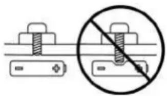
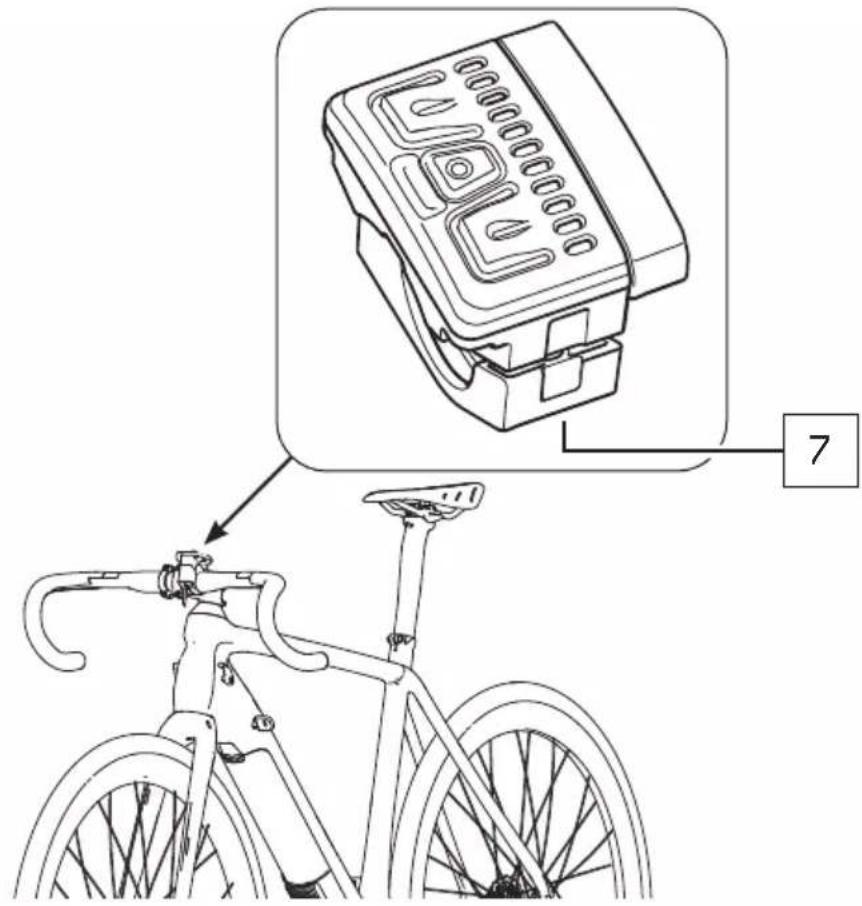
7. Mounting accessories on an e-bike.
An electric bicycle has hidden wiring through frame and has other critical e-bike parts like the drive unit and battery pack. When mounting accessories (e.g. a bottle cage), be sure not to impact the wiring or battery pack, e.g. by using too long or pointed bolts. This might cause a short circuit to the electric system and/or damage to the battery.
natural_image
Diagram showing a battery and screw with a prohibition symbol (no text or labels)WARNING.
A short circuit in the electric system and/or damage to the battery might lead to over-heating. In an extremely rare case, a battery pack that has been severely impacted could potentially catch fire.
8. Visit your dealer on a regular basis for maintenance of your new bicycle.
- Your dealer has the right knowledge and equipment to maintain your e-bike and to mount accessories safely.
- If you have questions about your new electric bicycle, ask your dealer!
Limited warranty
Your bicycle is covered by a Lifetime Limited Warranty.
Please visit our web site for details.
natural_image
Diagram showing a battery connected to a screw with a prohibition symbol (no text or labels)AVERTISSEMENT.
AVISO.
pedelec drive system
natural_image
Technical line drawings of various electronic devices including a battery, switch, and display unit (no text or symbols present)
FAZUA
Original instructions
U.S. Edition 2019 | EN
© 2019 Fazua GmbH
All Rights Reserved
Drive system: FUNDAMENTALS
1 Overview: Drive system....6
2 About this manual 8
2.1 Terminology and structure....8
2.2 Read and keep manual....8
2.3 Explanation of characters and symbols used....9
3 Safety....10
3.1 Functionality & intended use 10
3.2 Limitation of liability 10
3.3 Symbols & pictograms of the drive system....11
3.4 Important safety instructions....13
3.5 Notes on safe riding in road traffic....20
4 Usage....21
4.1 Attaching and removing components .....21
4.2 Switching the drive system on and off....24
4.3 Instructions for riding with the drive system....26
4.4 Switching on the drive system after standstill 27
4.5 Set support level....28
4.6 Using "Pushing support" mode 29
4.7 Charging the battery....30
5 Storage and transport 32
6 Optional accessories....33
7 Cleaning and maintenance....34
8 Troubleshooting....36
9 Disposal instructions ....38
9.1 Disposal of your e-bike....38
9.2 Battery disposal....38
10 Consumer Warranty ....39
11 Service....41
12 Conformity 41
Components: DRIVEPACK
13 Detailed view & part designations: Drivepack 42
14 Technical data....44
15 Using drivepack ....44
15.1 Mounting the drivepack on the e-bike....44
15.2 Remove drivepack from e-bike....46
15.3 Secure/lock drivepack from e-bike 47
Components: BOTTOM BRACKET
16 Detailed view & part designations: Bottom Bracket 48
17 Technical data....49
18 Using bottom bracket....49
18.1 Correct position/alignment .....50
18.2 Correcting incorrect position/alignment....50
Components: REMOTE
19 Model variants of the remote....52
20 Detailed view & part designations: Remote b....52
21 Technical data Remote b 54
22 Displays on the Remote b....54
22.1 Status display ....54
22.2 Display of charging level/support level....55
23 Using Remote b....56
23.1 Switching the drive system on and off....56
23.2 Setting the pedal support 57
23.3 Levels of support....57
23.4 "Pushing support" mode....58
24 Detailed view & part designations: Remote fX and Remote bX .....60
25 Technical data Remote fX and Remote bX....61
26 Displays on the Remote fX and Remote bX....61
26.1 Status display 62
26.2 Display of charging level/support level....62
27 Using Remote fX and Remote bX....63
27.1 Switching the drive system on and off....63
27.2 Setting the pedal support 64
27.3 Levels of support....65
27.4 Restart drive system 66
27.5 Rain mode....66
27.6 Switching bicycle lighting on and off 66
27.7 Bluetooth connectivity 67
Components: BATTERY
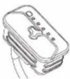
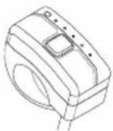
28 Model variants of the battery....68
29 Detailed view & part designations: Battery 69
30 Technical data....70
31 Using the battery....70
31.1 Checking and switching on battery....70
31.2 Inserting the battery into the drivepack 71
31.3 Removing the battery from the drivepack 73
31.4 Switching off the battery....73
31.5 Charging the battery....74
31.6 Charging process 75
31.7 Battery charge level indicator....76
Components: CHARGER
32 Model variants of the charger....77
33 Detailed view & part designations: Charger....77
34 Technical data....78
35 Using charger....79
35.1 Prepare charger....79
35.2 Connector charger to the battery 80
35.3 Unplug charger from battery 81
A
Drivepack
(Details from page EN-42)
natural_image
Technical line drawing of a mechanical component with curved and straight sections (no text or symbols)B
Bottom Bracket
(Details from page EN-48)

natural_image
Technical line drawing of a mechanical gear assembly (no text or symbols)C
Remote
(Details from page EN-52)
Remote b
Remote fX
Remote bX
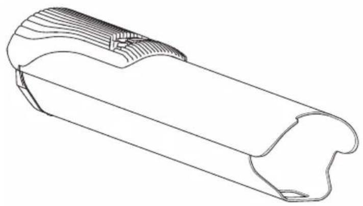
D
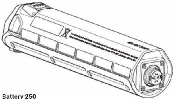
Battery
(Details from page EN-68)
natural_image
Technical line drawing of a battery with internal components and mounting holes (no text or symbols)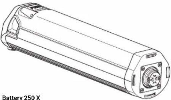
natural_image
Technical line drawing of a cylindrical battery with mounting flanges and internal components (no text or symbols on the diagram itself)E
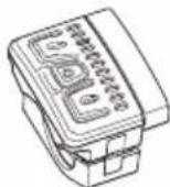
Charger
(Details from page EN-77)
Charger A Charger S (EU/US)
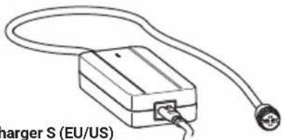
natural_image
Line drawing of a charger S (EU/US) connected to a cable and terminal block (no text or symbols on the diagram itself)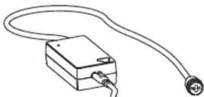
natural_image
Simple line drawing of a rectangular device connected to a terminal outlet (no text or symbols)
2 ABOUT THIS MANUAL
2.1 Terminology and structure
These original instructions are part of the Fazua evation drive system. In order to improve readability, the term "manual" will be used instead of the term "original instructions".
To facilitate orientation within the manual, it is divided into sections:
The first section "Fundamentals" deals with the drive system as a whole. In chapter 3 "Safety" you will find the basic information on intended use and important safety instructions. Chapters 4-8 ("Usage", "Storage and transport", "Optional accessories", "Cleaning and maintenance", "Troubleshooting") describe the procedures and steps to be taken. In chapters 9–12 you will find information on disposal instructions, consumer warranty, manufacturer and dealer service as well as conformity.
The remaining sections are dedicated to the individual components of the drive system: Here you will find detailed illustrations and additional information on the respective components. In addition, the steps listed in chapter 4 "Usage" are described in detail and supplemented with handling-specific warnings.
2.2 Read and keep manual
This manual contains all important information on the safety and use of the drive system as well as the individual components. It is based on the laws and regulations applicable in the United States, as well as national regulations such as UL® and ANSI testing standards.
Before using the drive system for the first time, be sure to read the complete manual - especially the "Safety" chapter - carefully. Failure to follow the instructions could result in serious injury to you or others and/or damage to the drive system or individual components.
Always keep this manual handy for further use and pass it on if you pass on the drive system or the equipped e-bike to third parties. In addition to this manual for the drive system, always observe the manufacturer's instructions for the e-bike in which the drive system is installed.
The Bluetooth® word mark and logos are registered trademarks of Bluetooth SIG, Inc. and are used by Fazua under license.
This manual may not be reproduced, modified, distributed or used in any way, in whole or in part, without prior written permission.
2.3 Explanation of characters and symbols used
Certain types of notes and information in this manual are identified by signs or symbols, which are listed below together with their meaning.
DANGER
High risk level! Risks that result in death or serious injury are indicated by the signal word "Danger".
WARNING
Moderate risk level! Risks that can result in death or serious injury are indicated by the signal word "Warning".
CAUTION
Lower risk level! Risks that may result in moderate injuries are indicated by the signal word "Caution".
NOTICE
Risks relating to damage to the product itself or to property damage to other objects are indicated by the signal word "Notice".

Useful additional information is marked with this information symbol.
3 SAFETY
3.1 Functionality & intended use
evation is designed as an electric drive system for e-bikes that are used as a means of transport by one person. From a speed of 20 mph (32 km/h), the electric pedal support switches off, so that at speeds above 20 mph (32 km/h) without motor support, you pedal exclusively with your own muscle power.
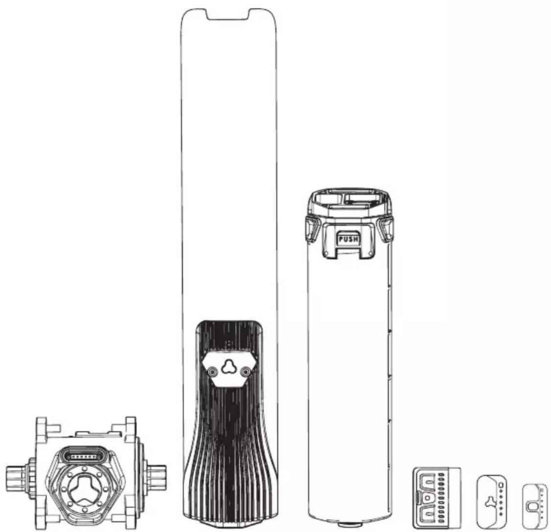
The drive system as a whole is made up of different, coordinated components.
These are:
A → Drivepack (incl. locker for locking to the frame),
B → Bottom Bracket (incl. Speed Sensor + spoke magnet),
C → Remote (Remote b, Remote fX, Remote bX),
D → Battery (Battery 250, Battery 250 X),
E → Charger (Charger A, Charger S (EU/US)).
The version of the drive system installed in your e-bike, i.e. the specific combination of component variants, is specially adapted to your e-bike and must therefore not be changed.
Categorically, the installation of the drive system and certain work on it may only be carried out in the ways planned by the manufacturer or by an authorized specialist. Authorized specialists for repair and maintenance work can be found with the official Fazua Servicepartners (see chapter 11 "Service").
For information on which work you can carry out yourself and which work must be carried out by an authorized specialist, refer to the separate sections on the individual components.
3.2 Limitation of liability
Fazua accepts no liability for damage caused by incorrect or improper installation or use other than that intended. Only use the drive system as described in this manual. Any other use is considered improper and may result in accidents, serious injury and damage to the drive system.
3.3 Symbols & pictograms of the drive system
On individual components of the drive system you will find certain symbols and pictograms, which are listed below including their meaning.

This symbol indicates that the user of the drive system or the individual components must have read and understood these original instructions before using it.
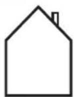
A device marked with this symbol (here: the charger) may only be used in dry indoor areas.
DANGER
When used in a humid environment and in contact with liquids, there is a risk of electric shock!

An electrical appliance marked with this symbol corresponds to protection class II: The device has double or reinforced insulation to protect against electric shock.
This symbol warns of hot surfaces.
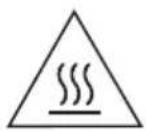
DANGER
There is a burning risk if touched, contact with combustible materials may cause a fire.
These symbols indicate that the lithium-ion battery must be disposed of separately at the end of its life and must not be disposed of with household waste.

The symbols must be affixed in the European Union in accordance with the laws and directives in force there.
Li-ion
This symbol indicates that the marked component must be disposed of separately as electrical or electronic equipment at the end of its service life and must not be disposed of with household waste.
The symbol must be affixed in the European Union in accordance with the laws and directives in force there.
 | This symbol indicates products that meet all the requirements for obtaining the European CE marking. |
 | The test seal "Geprüfte Sicherheit" (GS mark) is awarded by independent certification bodies.A device marked with the GS test seal complies with the safety-relevant requirements of the German Product Safety Act (ProdSG). |
 | The "UL®-Listed" seal of approval is awarded by the US UL® Certification Body.A device marked with the "UL®-Listed" test seal shown corresponds to the safety-relevant requirements for Canada and the USA. |
 | The accompanying test seal is awarded by the SGS certification body.A device marked with this test seal complies with the safety-relevant requirements for Canada and the USA in accordance with UL Standards.The drive system and the battery were tested according to UL Standards. The following UL Standards were applied: UL 2271 - Standard for Batteries for Use In Light Electric Vehicle (LEV) Applications, UL 2849 - Outline of Investigation for Electric Bicycles, Electrically Power Assisted Cycles (EPAC Bicycles), Electric Scooters, and Electric Motorcycles. |
 | The FCC seal is awarded by the Federal Communications Commission, an independent U.S. government agency responsible for implementing and enforcing U.S. communications laws and regulations.An electrical device marked with the FCC seal complies with American standards for electromagnetic compatibility. |
3.4 Important safety instructions
READ AND KEEP ALL IMPORTANT SAFETY INSTRUCTIONS!
The following important safety instructions must always be observed when using and handling the drive system.
DANGER
Dangers for users of e-bikes!
Basically there are specific dangers for the users of e-bikes, e. g. danger of accidents when riding in road traffic. Dangers arising from handling the corresponding e-bike model in which the drive system is installed are dealt with in the separate instructions of the e-bike manufacturer. Depending on your country or location, there may also be additional legal requirements that you must observe when using your e-bike. If you do not fully inform yourself about existing dangers before using your e-bike equipped with the drive system, there is an increased risk of accident and injury.
▶ Read and follow the manufacturer's instructions for your e-bike.
▶ Find out about and observe any applicable national regulations regarding e-bikes.
! DANGER
Danger of battery explosion!
If you use inappropriate batteries or do not handle the battery properly, the battery may explode.
▶ Only use original Fazua evation batteries approved by the e-bike manufacturer.
▶ Never use a damaged battery and never try to charge a damaged battery!
▶ Never open the battery! If you try to open the battery, there is an increased risk of explosion!
▶ Keep the battery away from heat (e.g. strong sunlight), open fire or water or other liquids.
! DANGER
Dangers during unattended use!
Basically there are specific dangers dangers for children (younger than 14) and persons with reduced physical, sensory and mental abilities (e.g. partially handicapped persons, older persons with limited physical and mental abilities) or a lack of experience and knowledge (e.g. older children)!
If, for example, children or people with physical or mental impairments handle the battery or charger, there is an increased risk potential as these user groups may not be able to correctly assess certain risks, for example.
This appliance is not intended for use by children (younger than 14) and persons (including children) with reduced physical, sensory or mental capabilities, or lack of experience and knowledge, unless they have been given supervision or instruction concerning use of the appliance by a person responsible for their safety.
▶ Children shall not play with the appliance.
▶ Only for rechargeable li-ion battery.
▶ Don't attempt to disassemble the charger by yourself.
▶ Don't use the charger in high temperature, moist, inflammable or explosive outdoor environments.
▶ Disconnect the power supply before marking or breaking the connections to the battery.
! DANGER
Danger of impairment of medical devices!
The magnetic connections in the battery and charger can interfere with the function of pacemakers.
▶ Keep the battery and charger away from pacemakers or persons wearing a pacemaker and draw the attention of persons with pacemakers to the danger.
! DANGER
Risk of electric shock!
Improper handling of the charger or incorrect mains connection may expose you and others to the risk of electric shock.
▶ Only connect the charger to an easily accessible and properly installed power outlet.
▶ Make sure that the mains voltage at the mains connection corresponds to the information on the charger.
▶ Only use the charger in dry indoor areas.
▶ Keep the charger away from any liquid or moisture.
▶ Do not pull on the mains or charging cable to pull the respective cable out of a socket or outlet, but always hold the corresponding plug.
▶ Do not handle the plugs of the power cord and charging cable with wet or damp hands.
▶ Take care not to bend the power cord and charging cable or lay them over sharp edges.
▶ Do not open the charger without authorization. The charger may only be opened by an authorized specialist and repaired using original spare parts.
Before each use of the charger, check all individual parts (mains adapter, mains cable, charging cable and all plugs) for damage. If the charger's power cord is damaged, it must be replaced by an authorized specialist to avoid hazards.
▶ Never use a damaged charger. Otherwise there is a high risk of electric shock!
▶ Keep the charger in a clean condition. There is an increased risk of electric shock if the charger is dirty or contaminated.
▶ Only use the battery in e-bikes equipped with an original Fazua evation drive system. Never use the battery for other purposes or in other drive systems.
DANGER
Dangers due to unauthorized changes!
If you make unauthorized changes to the drive system or components, you may cause an explosion, electric shock, or serious injury to yourself or others.
▶ Under no circumstances should you modify or alter individual components of the drive system autonomously.
▶ Never replace any components of the drive system without authorization.
▶ Never open the drive system components without authorization. The drive system components do not require any maintenance. Only allow repairs to the drive system to be carried out by an authorized specialist.
▶ Only allow components of the drive system to be replaced by an authorized specialist with permissible original spare parts.
! DANGER
Fire hazard due to incorrect handling!
If you handle the battery and/or charger improperly or use incompatible batteries and chargers together, they may cause a fire.
▶ Follow all charging instructions and do not charge the battery outside of the temperature range specified in the instructions. Charging improperly or at temperatures outside of the specified range may damage the battery and increase the risk of fire.
▶ Do not modify or attempt to repair the charger or the battery.
▶ To charge the battery, use only original and compatible evation chargers from Fazua.
▶ Take care not to handle metal objects such as coins, paper clips, screws, etc. in the immediate vicinity of the battery and to store the battery separately from metal objects. Metal objects can close a circuit between the terminals of the battery (i.e. "short-circuit" the battery) and so cause a fire.
▶ Do not short-circuit the battery.
▶ Battery and charger may heat up during charging or operation. It is therefore essential to keep the battery and charger away from flammable materials. Pay particular attention during the charging process and always move the battery and charger to a dry and fireproof place before charging.
▶ Do not leave the battery and charger unattended during charging.
WARNING
Risk of caustic burns due to battery acid!
The battery contains battery acid. If you come into contact with this fluid, the affected skin area and/or mucous membrane may be burnt. Eye contact can cause loss of vision.
▶ Do not touch any liquid leaking from the battery.
▶ Should you ever come into contact with battery acid, immediately rinse the affected body part thoroughly under plenty of running water.
▶ Consult a doctor immediately after rinsing, especially in case of eye contact and/or if mucous membranes (e.g. nasal mucosa) are affected.
WARNING
Health hazard due to irritation of the respiratory tract!
If the battery is damaged, gases may escape which may irritate the respiratory tract.
▶ Protect the battery from mechanical influences and any other load.
If you notice or suspect that gas is leaking from the battery, immediately ensure a supply of fresh air and seek medical attention as soon as possible.
WARNING
Danger from accidental starting!
Starting the drive system in unsuitable situations can result in accidents and serious injury.
Remove the drivepack from the e-bike while the e-bike is being transported or stored and during all work on the e-bike to prevent the drive system from being started accidentally.
▶ Use the "Pushing support" function only when pushing the e-bike. While the pushing support is activated, you must hold the e-bike securely with both hands and the wheels must be in contact with the ground, otherwise there is a risk of injury.
WARNING
Risk of burns!
The radiator in the drivepack can become very hot during operation so that you can burn yourself on it.
▶ Be careful when handling the drivepack.
▶ Allow the drivepack to cool down completely before touching the drivepack.
NOTICE
Risk of damage!
Improper handling can damage the drive system or individual components.
▶ Have individual components of the drive system and the e-bike replaced exclusively by identical components or other components expressly approved by the e-bike manufacturer. This will protect the other components or your e-bike from possible damage.
▶ Never use your e-bike without a drivepack or without a downtube cover if you use it as a conventional bicycle without a drivepack.
Remove the battery before cleaning the drivepack and allow all components to dry completely before inserting. If the battery comes into contact with damp or wet contacts on the drivepack during insertion, the battery may be damaged.
When charging the battery, make sure that the mains cable and charging cable of the charger are not trip hazards in order to prevent components from being damaged, e.g. by a fall.
3.5 Notes on safe riding in road traffic
By following the road safety precautions listed below, you can reduce the risk of accidents and injuries when riding a bicycle or e-bike in road traffic.

The term "road traffic" also refers to private areas open to the public and to field or forest paths open to the public.
▶ Only ride your e-bike on the road if the equipment complies with national road traffic regulations. Please contact your e-bike manufacturer for more information.
▶ Find out about the regulations applicable to road traffic in your country or region, e.g. from the Ministry of Transport. You should also keep yourself informed about any changes to the contents of the valid regulations.
▶ Observe and follow national and regional road traffic regulations.
When riding, use a suitable bicycle helmet that complies with national and regional regulations (CPSC (Consumer Product Safety Commission, 16 CFR Part 1203 or ASTM F1447-06).
When riding, wear light-colored clothing with reflective elements to attract the attention of other road users.
▶ Do not ride your e-bike if you are under the influence of alcohol, narcotics or medications.
▶ Do not use mobile devices such as smartphones, MP3 players, etc. while riding.
▶ Do not distract yourself while riding by other activities such as switching on the light. Stop to carry out such activities.
▶ Never ride without your hands, under any circumstances. Always keep both hands on the handlebars.
▶ Ride carefully and be considerate of other road users.
▶ Rive in such a way that nobody is harmed, endangered, obstructed or annoyed.
▶ Ride on prescribed lanes for bicycles.
4 USAGE
This chapter describes chronologically how to proceed when using the drive system.
! DANGER
Incorrect or improper handling may result in explosion, fire or accidents and serious injury.
▶ You must read the detailed descriptions in the section for the relevant component:
- before you use your e-bike equipped with the evation drive system for the first time,
• if you are unsure how to use it,
- if you have problems carry out the handling steps described here.
4.1 Attaching and removing components
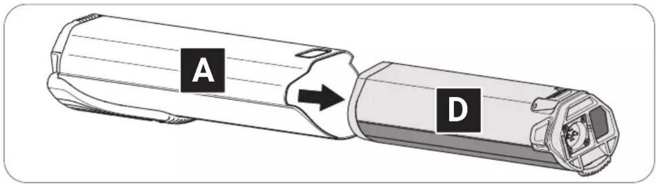
4.1.1 Inserting the battery into the drivepack
→ More detailed information can be found in chapter 31.1 "Checking and switching on battery" and in chapter 31.2 "Inserting the battery into the drivepack".

On delivery, the battery may only be precharged.
▶ Fully charge the battery before inserting it into the drivepack for the first time.
! DANGER
Risk of explosion and fire!
A damaged or dirty battery may explode and/or cause a fire.
▶ Never insert a damaged battery into the drivepack.
▶ Check the battery for visible damage, such as cracks or burn marks, before each insertion.
▶ Make sure that the interfaces on the battery are free of dirt before using it.
- Check the battery for visible damage.
-
Press the on/off button on the battery once to turn on the battery.
-
Place the battery with the connecting contact first on the battery holder of the drivepack.
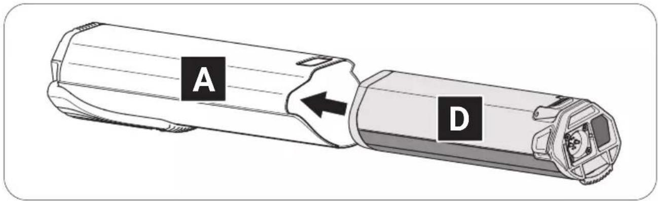
- Carefully insert the battery as far as possible into the battery holder until you hear a click.
The battery is automatically locked when you have inserted it correctly. If the battery does not lock, repeat the procedure. Do not use the drive system if the battery cannot be locked. If the unlocked battery falls out of the e-bike holder while riding, this can lead to an accident/fall and damage the battery.
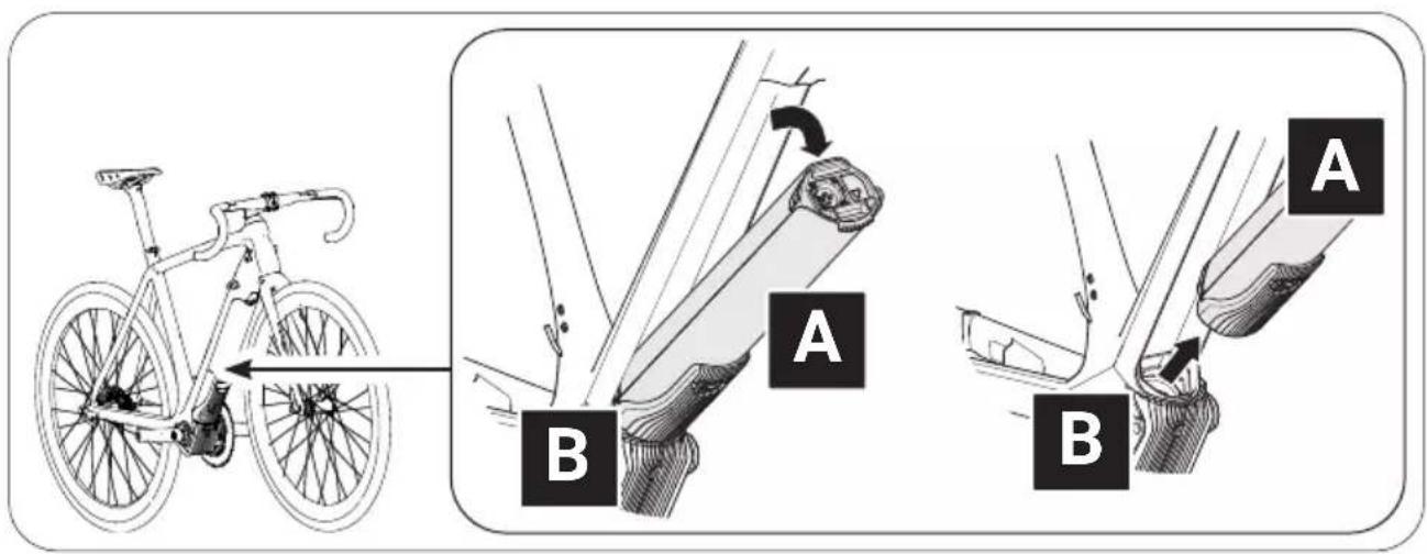
4.1.2 Mounting the drivepack on the e-bike
→ More detailed information can be found in chapter 15.1 "Mounting the drivepack on the e-bike".
- Place the drivepack with the interface for the bottom bracket in front of the corresponding interface on the bottom bracket.
- Swing the upper end of the drivepack into the down tube of the e-bike. The drivepack is automatically locked in place when the two interfaces on the drivepack and the bottom bracket are correctly engaged and the drivepack is fully swiveled into the intended position on the down tube.
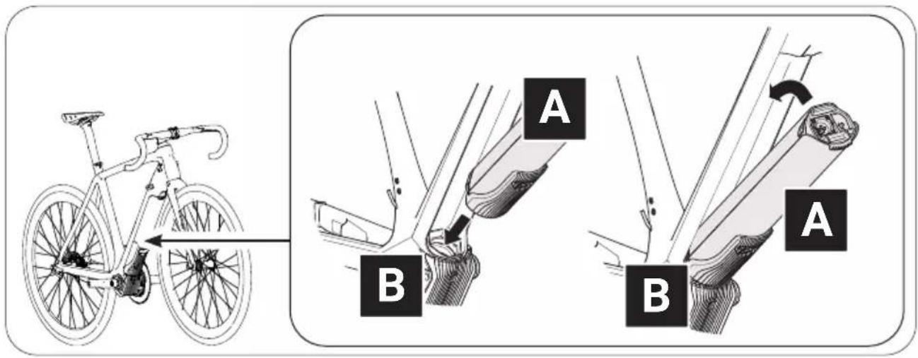
- Check the drivepack makes a tight fit.
If the drivepack does not lock, repeat the procedure. Do not use the drive system if the drivepack cannot be locked to the e-bike. If the unlocked drive unit falls out of the e-bike holder while riding, this can lead to an accident/fall and damage the drive unit or the battery.
4.1.3 Remove drivepack from e-bike
→ More detailed information can be found in chapter 15.2 "Remove drivepack from e-bike".
WARNING
Risk of burns!
The radiator in the drivepack can become very hot during operation so that you can burn yourself on it.
▶ Let the drivepack to cool down completely before touching the drivepack.
- Secure the drivepack with one hand.
- Press the push button or move the locking lever upwards as far as possible to release the drivepack from the lock.
- Press and hold the push button and carefully lower the drivepack. The locking lever automatically remains in the open position.
- Remove the drivepack from the interface on the bottom bracket.
4.1.4 Removing the battery from the drivepack
→ More detailed information can be found in chapter 31.3 "Removing the battery from the drivepack".
CAUTION
Pinch risk!
You can pinch your fingers when removing the battery from the drivepack.
▶ When pressing the push button or removing the battery, be careful not to pinch your fingers.
- Secure the battery with one hand.
- Press the push button as far as it will go to release the battery from the lock.
- Press and hold the push button and gently pull the battery out of the battery holder.
4.2 Switching the drive system on and off

Appearance and handling of the model-dependent remotes differ to some extent.
→ More detailed information can be found in chapter 19 "Model variants of the remote".
▶ Pay attention to that information which applies precisely to your remote from the whole list here. If none of the model variants is explicitly mentioned, the descriptions refer to all remotes.
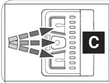
4.2.1 Switch on drive system
→ More detailed information can be found in chapter 23.1 "Switching the drive system on and off" or in chapter 27.1 "Switching the drive system on and off".
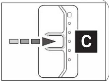
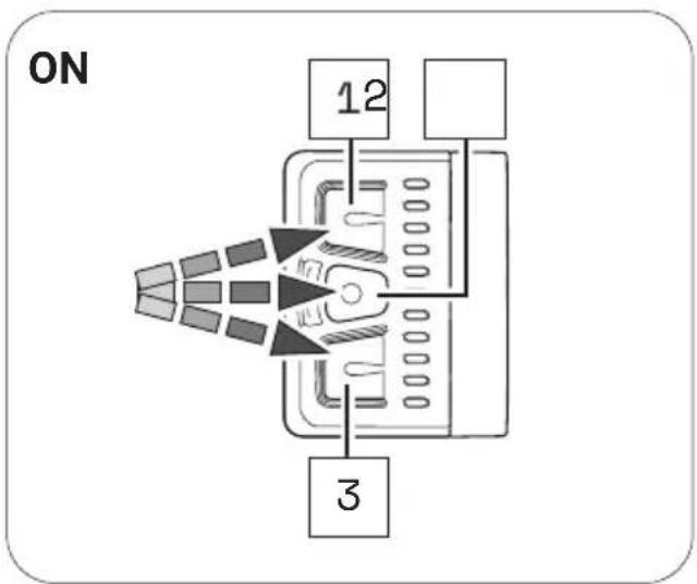
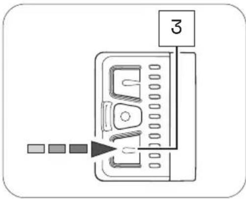
▶ Turn on the drive system using the Remote b by pressing one of the three buttons.
or
▶ Turn on the drive system using the Remote fX or Remote bX by pressing the center button.
natural_image
Diagram of a device emitting heat or radiation beams from a tray, with a labeled component 'C' (no text or symbols on the diagram itself)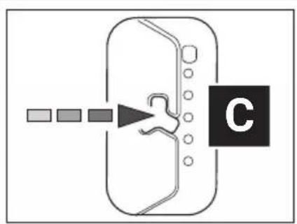
flowchart
graph TD
    A["Start"] --> B{Decision}
    B --> C["Step 1"]
    B --> D["Step 2"]
    B --> E["Step 3"]
    B --> F["End"]
flowchart
graph TD
    A["Input"] --> B{Decision}
    B --> C["C"]
    style C fill:#000,stroke:#fff,color:#fff
4.2.2 Switch off drive system
→ More detailed information can be found in chapter 23.1 "Switching the drive system on and off" or in chapter 27.1 "Switching the drive system on and off" as well as in chapter 4.4 "Switching on the drive system after standstill" as .
You can switch off the drive system in various ways:
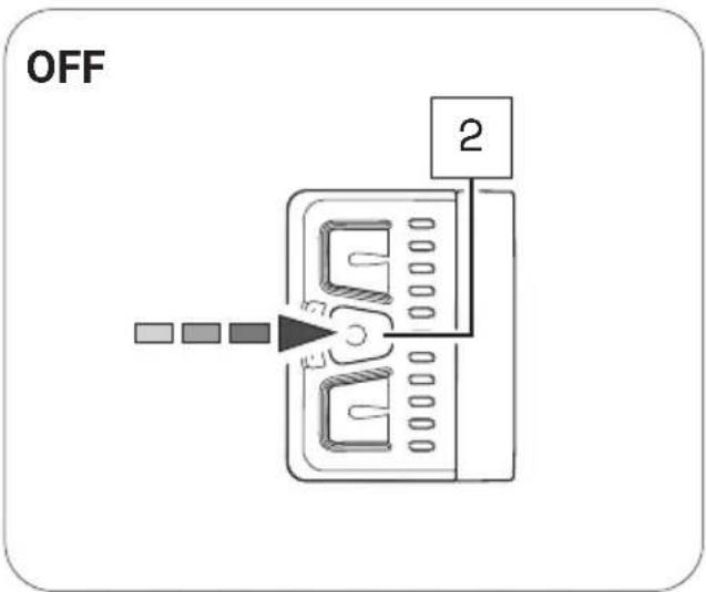
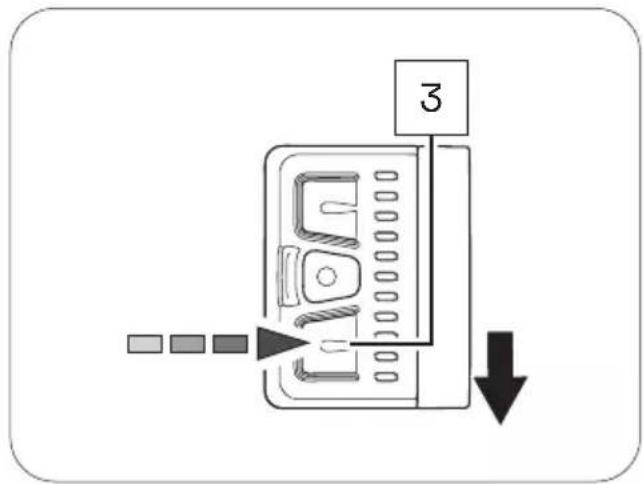
▶ Press and hold the center button on the remote for 2 seconds (Remote b) or 1 second (Remote fX and Remote bX) to turn off the drive system.
or
▶ Remove the drivepack from your e-bike.
or
▶ Turn off the battery by pressing the on/off button.

In addition to the drive system, Fazua also recommends switching off the battery if you park your e-bike for a longer period of time (e.g. if you take a break during a trip).
→ More detailed information can be found in chapter 31.4 "Switching off the battery"
4.3 Instructions for riding with the drive system
Observe the following instructions for riding your e-bike equipped with the evation drive system.
Gear change:
The gearshift of your e-bike can be operated in the same way as that of a conventional bicycle. Selecting a suitable gear increases the speed, power and range of your e-bike while maintaining pedal frequency.
Irrespective of the type of gearshift mounted, the following applies:
▶ Stop pedaling when you change gears. This relieves the load on the rear derailleur and the drive of your e-bike.
Range/trip planning:
How long or how far you can ride your e-bike before you need to recharge the battery depends on several factors.
These factors include, but are not limited to:
• the set support level;
• the (riding) speed with which you move;
- your gear changing;
• the type of tire and the tire pressure set;
• the chosen route and weather conditions;
• the weight of driver and e-bike (total weight);
• the condition and age of the battery
The following therefore applies as a matter of principle:
▶ Familiarize yourself with your e-bike step by step and away from roads and heavy traffic.
▶ Test the maximum range of your e-bike under various external conditions before planning longer trips. An exact statement about the range of your system is neither possible before nor during a trip.
Storage and operating temperatures
▶ Observe the operating and storage temperatures for the components of the drive system and for the components of your e-bike - especially for the battery, as it can be damaged by extreme temperatures.
DANGER
If you do not handle the battery properly, the battery may explode!
4.4 Switching on the drive system after standstill

Your e-bike will come to a standstill as soon as it is switched off.
• After 15 minutes of standstill, the drive system (not the battery!) switches off automatically.
The drive system can be turned on again by briefly pressing the center button on the control panel.
- The battery switches off after 8 hours of standstill (provided no button/touch sensor is pressed during this time).
- After 3 hours of standstill (provided that the charge level of the battery falls below 30% and no button/touch sensor is pressed during this time), the battery switches off.
▶ Switch on the Battery 250 X by pressing the on/off button to be able to use the drive system again after the battery has automatically switched off due to a standstill.
4.5 Set support level
→ More detailed information can be found in chapter 23.2 "Setting the pedal support" or in chapter 27.2 "Setting the pedal support" as well as in chapter 23.3 "Levels of support" or in chapter 27.3 "Levels of support".
With the help of the remote you can set the desired support level at any time - even while riding.
▶ Press the upper button/touch sensor on the remote to switch to the next higher support level.
▶ Press the lower button/touch sensor on the remote to switch to the next lower support level.
| OVERVIEW TABLE "SUPPORT LEVELS" | ||
| Support level Color max. motor power | ||
| none white 0 | W | |
| Breeze green 400 W* | ||
| River | blue | 400 W* |
| Rocket | pink | 400 W* |
* The values given here are the "theoretical" maximum motor power. The "actual" maximum motor power is configured by the manufacturer of your e-bike, depending on the model.
4.6 Using "Pushing support" mode

If your e-bike is equipped with a Remote b, it has the "Pushing support" mode, which you can use when pushing the e-bike.
→ More detailed information can be found in chapter 23.4 ""Pushing support" mode".
WARNING
Danger from accidental starting!
Starting the drive system in unsuitable situations can result in accidents and serious injury.
▶ Use the "Pushing support" function only when pushing the e-bike.
When the pushing support is activated, hold the e-bike securely with both hands and make sure that the wheels are in contact with the ground.
CAUTION
Risk of injury!
If you push the e-bike with the pushing support activated, the pedals rotate slowly and you may be injured.
▶ Be careful not to injure yourself on the rotating pedals when using the "Pushing support" function.
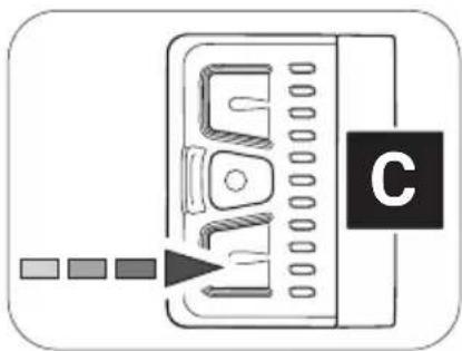
-
If necessary, change to the support level "none".
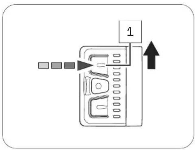
-
Press and hold the lower button on the Remote b to activate the pushing support mode.
After 2 seconds the pushing support is activated and sets the e-bike in motion as long as you keep the button pressed.
natural_image
Diagram of a device with a labeled component 'C' and three colored square indicators pointing to its left side (no text or symbols on the device itself)-
Guide the e-bike with both hands and, if necessary, brake the speed of the e-bike to your own walking speed by holding or restraining the e-bike while pushing.
-
Switch off the pushing support by releasing the lower button.
4.7 Charging the battery
DANGER
Risk of electric shock and fire!
If you use the charger improperly, you and others may be exposed to the risk of electric shock or you could cause a fire.
▶ Read and follow the handling-specific warnings in the section for the charger and the battery.
WARNING
Risk of burns!
The radiator in the drivepack can become very hot during operation so that you can burn yourself on it.
▶ Let the drivepack to cool down completely before touching the drivepack.

You can either leave the battery in the drivepack during charging or remove it from the drivepack and charge it separately.
- Before charging the battery, prepare the charger by connecting the power cord to the power supply.
→ More detailed information can be found in chapter 35.1 "Prepare charger". - Remove the drivepack from the e-bike.
→ More detailed information can be found in chapter 15.2 "Remove drivepack from e-bike". - Insert the charging plug into the charging socket on the battery.
→ More detailed information can be found in chapter 35.2 "Connector charger to the battery".
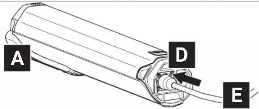
- Plug the power plug into a suitable wall outlet to establish the power connection.
The charging process starts automatically after connection to the mains.
→ More detailed information can be found in chapter 31.6 "Charging process" and in chapter 31.7 "Battery charge level indicator".
-
Disconnect the charger from the mains by unplugging the mains plug from the socket when charging is complete or to interrupt charging.
-
Disconnect the charger from the battery by pulling the charger plug out of the charging socket on the battery.
→ More detailed information can be found in chapter 35.3 "Unplug charger from battery".
5 STORAGE AND TRANSPORT
WARNING
Danger from accidental starting!
Starting the drive system in unsuitable situations can result in accidents and serious injury.
▶ Always remove the drivepack with the battery before transporting your e-bike or stowing/storing it for a longer period of time.
▶ When transporting and storing your e-bike or the components of the drive system, observe the specified temperature ranges for the components.
▶ Always transport and store the battery separately from the e-bike.
Batteries are subject to the dangerous goods regulations. Undamaged batteries may be transported by private individuals in road traffic. Commercial transport requires compliance with the rules on the packaging, labeling and transport of dangerous goods. Open contacts must be covered and the battery securely packed. When sending, the parcel service must be informed of the presence of dangerous goods in the packaging.
▶ Please note the following information on the charge level of the battery during prolonged non-use and the information on the temperature ranges for the corresponding storage periods.
The battery should have a charge level of at least 60% if you plan not to use it for an extended period of time. Check the charge status of the battery after 6 months of non-use: If the test shows that the charge level is 20% or less, recharge the battery to at least 60% charge level.
Consider the following storage time-dependent temperature ranges for the battery (charge level 60 %):
- <1 month storage time: 5 to 140^ (-15 to 60^ )
• 3 months storage time: 5 to 113 °F (-15 to 45 °C)
• 1 year storage time: 5 to 77 °F (-15 to 25 °C)
▶ If you have further questions, please contact a Fazua Servicepartner or visit the official Fazua service platform (www.fazua.com/help).
6 OPTIONAL ACCESSORIES
Downtube Cover
NOTICE
Risk of damage!
If you use the e-bike or bicycle without the drivepack inserted and the opening for the drivepack on the down tube of the frame remains unlocked, components of the drive system may be damaged.
When using the e-bike as a conventional bicycle without a drivepack, close the opening for the drivepack on the down tube of the frame using the optional Downtube Cover.
You can easily use your e-bike as a conventional bicycle without an electric drive system by removing the drivepack.
You can use the optional Downtube Cover to cover the free opening in the down tube after removing the drivepack. You can use the remaining internal space as storage space, e.g. for repair kit, tools or food.
▶ If you have any further questions about the optional evation Downtube Cover, please contact a Fazua Servicepartner or visit the official Fazua service platform (www.fazua.com/help).
Fazua Rider App by CoModule:
Depending on the model, your remote is equipped with a Bluetooth® function. This enables you to connect a mobile device (e.g. your smartphone) to the remote and to display and evaluate certain ride data etc. with the help of the Fazua Rider App.
▶ If you have any questions about the Fazua Rider App, please contact a Fazua Servicepartner or visit the official Fazua service platform (www.fazua.com/help).
All remotes with the serial number 1805113000 or higher are Bluetooth® compatible ex works.
▶ Contact a Fazua Servicepartner if the control you have installed is not Bluetooth®-enabled.
7 CLEANING AND MAINTENANCE
CAUTION
Risk of injury!
If the drive system is set in motion while you are handling it, you may jam your fingers or otherwise injure yourself.
Remove the drivepack from the e-bike when cleaning the e-bike or the drive system components.
NOTICE
Risk of damage!
Improper cleaning may damage the drive system or individual components.
▶ Never immerse the drive system components in water or other liquids for cleaning.
▶ Do not use aggressive cleaning agents for cleaning.
▶ Do not use sharp, angular or metallic cleaning objects when cleaning.
▶ Never clean the drive system components with a hard water jet or a high-pressure cleaner.
▶ Always keep all components of the e-bike and the drive system in a clean condition.
▶ Clean the components gently with a cloth or soft brush.
▶ Wipe all surfaces and components dry after cleaning.
▶ Pay particular attention to the contacts and interfaces between battery and drivepack and between drivepack and bottom bracket: The interfaces must not be soiled or contaminated and must be completely dried before inserting the components to avoid damage.
▶ Clean the radiator of the drivepack regularly.
Do not clean the radiator only when it is visible or heavily soiled!
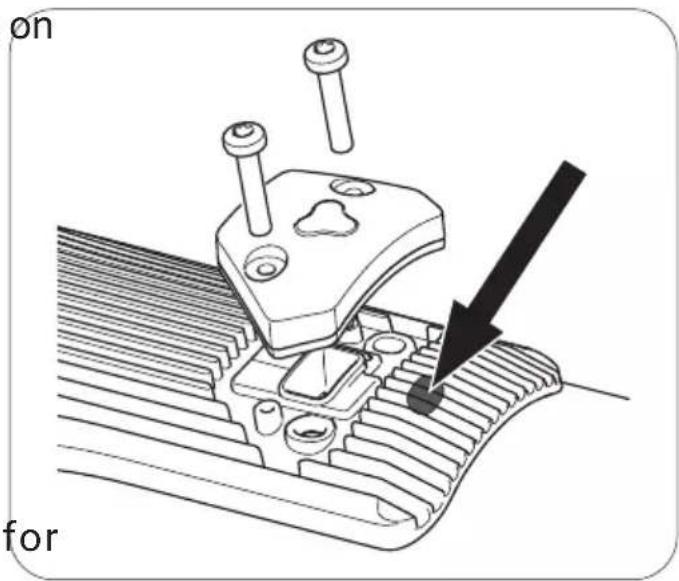
▶ Keep the drainage opening the colling body clean or clear to ensure that splash water and/or condensate can drain easily from the drivepack.
The drainage opening is located on the radiator directly above the USB port or the corresponding cover (see illustration on the right).
▶ Lubricate the locker for locking the drivepack to the
frame approximately every 2-3 months or at the latest as soon as it is no longer convenient to operate.
For more information on cleaning and maintaining your drive system, contact a Fazua Servicepartner or visit the Fazua service platform (www.fazua.com/help).
8 TROUBLESHOOTING
- If your e-bike or drive system does not function as desired, first check whether the fault can be rectified using the following overview table "Troubleshooting".
-
If necessary, contact a Fazua Servicepartner or visit the Fazua service platform (www.fazua.com/help), if:
-
the error is not listed in the overview table,
- the error is listed in the overview table, but it cannot be corrected in the way described here or you are unsure.
| OVERVIEW TABLE "TROUBLESHOOTING" | |
| Problem possible Reason / Solution | |
| The engine feels weaker than usual. | The drive system is brand new.► Wait until the drive system is "run in". The drive system needs a few miles to develop its full power. |
| It is very hot and the heat management of the battery and/or drivepack limits the performance. | |
| It is very cold, so the lithium-ion battery does not provide the usual performance. | |
| The drivepack cannot be clicked out of the down tube. | The locker is defective. Dirt could block the locker. Maybe you rode without a drivepack in bad weather conditions.► Contact a Fazua Servicepartner. |
| The drivepack makes buzzing noises. | The polygon sleeve moves.► Contact a Fazua Servicepartner. |
| The drivepack makes clicking noises. | The polygon coupling was loaded on one side.► Push the polygon coupling back into its original position to mobilize it again. |
| The upper LED on the remote lights up/ flashes red. | There is a connection error between drivepack and bottom bracket.Contamination at the interface may prevent the connection.► Clean the interface between the bottom bracket and the drivepack. |
| The upper LED on the remote lights up/ flashes yellow. | There may be a bad connection between the speed sensor and the bottom bracket.► Check the position of the spoke magnet. If you cannot find a fault, contact a Fazua Servicepartner. |
| The white LEDs on the remote flash. | Software update► After a new firmware update, the remote is updated automatically. In this case, please wait and do not switch off the remote until the LEDs stop flashing. |
| The remote cannot be switched on. | The battery is flat or has switched off due to a longer rest period (standstill).► Try turning on the battery using the on/off button.► Charge the battery if necessary. |
| The interface between the battery and the drivepack may be dirty.► Clean the interface between the battery and the drivepack. | |
| The battery cannot be inserted into the drivepack. It does not lock into the battery compartment. | The interface between the battery and the drivepack may be dirty.► Clean the interface between the battery and the drivepack. |
| The pedal support suddenly fails during the ride | BMS protection function► Turn off the battery by pressing the on/off button for 3 seconds and then turn it on again. |
9 DISPOSAL INSTRUCTIONS
According to the EU Directives for waste electrical and electronic equipment (Directive 2012/19/EU) and spent batteries (Directive 2006/66/EC), the relevant components must be collected separately and disposed of in an environmentally sound manner.
Before disposing of your e-bike, remove all batteries and all components and controls that contain batteries.
9.1 Disposal of your e-bike
After you have removed all batteries, the e-bike is considered an old electrical appliance and must be recycled.
▶ Find out from your city or municipal administration (municipality, district) about free collection points for old electrical appliances and/or collection points, via which the components or the e-bike can be recycled.
When disposing of the product, observe the requirements of the United States Environmental Protection Agency (www.epa.gov).
If necessary, make sure to delete any personal data stored on the device before you return the electrical or electronic equipment to the collection point. This task is your responsibility.
9.2 Battery disposal
The drive system battery is a lithium-ion battery that must be disposed of as hazardous waste.
▶ Dispose of the battery of the drive system and any other batteries installed in the e-bike at a recycling center or a collection point in your town or municipality.
▶ If required, visit the website of call2recycle: www.call2recycle.org. You will find extensive content here on the subject of "Recycling batteries", as well as a search function for collection points in your area.
10 CONSUMER WARRANTY
FAZUA GmbH, warrants to the end Customer (hereinafter referred to as the "Customer"), in accordance with the provisions set forth below, that the drive system integrated in the bicycle purchased by the Customer, including the components of the drive system, (hereinafter collectively referred to as the "Product") will remain free of construction, material and manufacturing defects and be fully functional for a period of two years following delivery to you (warranty period).
However, in the event that a defect should occur, or if the drive system does not remain fully functional, the FAZUA GmbH shall, at its own discretion, remedy the defect(s) at its own expense by either performing repairs or providing new or refurbished parts.
However, claims under this warranty shall only be deemed valid if:
- The Product does not exhibit any damage or signs of wear caused by a form of use deviating from normal intended use or the specifications provided by FAZUA GmbH in the user manual.
• The Product does not exhibit any signs indicating that repairs or other procedures were performed by anyone not authorized by FAZUA GmbH.
- The damage is not due to improper assembly or follow-up maintenance or lack of skill, competence or experience of the user or assembler.
• The Product was assembled or serviced by an authorized Fazua dealer.
- The Product has not been modified, neglected, used in competition, or for commercial purposes such as rental, courier, police, security, etc., misused or abused, involved in accidents or anything other than normal use.
- There was no installation of components, parts, or accessories not originally intended for use with or compatible with Fazua Products.
• The serial number has not been removed or rendered illegible.
- Notice of the defect has been given within fourteen (14) days of the discovery of the defect.
Claims under this warranty require that,
- prior to returning the Product, the Customer contact either the dealer from whom the Customer purchased the bicycle or FAZUA GmbH, and that the Customer gives the dealer or FAZUA GmbH an opportunity to perform a fault analysis over the telephone within a period of eight days.
• the Product is delivered or returned to FAZUA GmbH. - the original invoice containing the date of purchase is presented.
- the shipping is carried out by a carrier designated by FAZUA GmbH. The Customer may use a different carrier at his own expense.
In the event of resale, this warranty shall also apply within the aforementioned scope, and under the conditions stated above (including the requirement to provide proof of purchase) to any subsequent future owner of the Product. Each new owner assumes the warranty based on the time remaining from the original date of purchase.
In consideration of the above warranties by FAZUA GmbH, the buyer agrees to and accepts the following conditions:
- This warranty is subject to the law of the US, provided that mandatory consumer protection regulations in the country of the respective Customer are not in conflict therewith.
- That this warranty is in lieu of all other warranties, expressed or implied.
- That ALL WARRANTIES OF MERCHANTABILITY OR OF FITNESS FOR A PARTICULAR PURPOSE ARE HEREBY EXCLUDED AND/OR WAIVED.
- That this remedy is in lieu of all other remedies or claims for damages, consequential or otherwise, which the buyer may have against FAZUA GmbH.
- FAZUA GmbH shall have no liability for any loss or injury caused, in whole or in part, by its actions, omissions, or negligence, or for contingencies beyond its control.
11 SERVICE

Authorized specialists for repair and maintenance work can be found with the official Fazua Servicepartners. Contact the Fazua service team or visit the Fazua service platform to find Fazua Servicepartners for your region.

If possible, prepare the error image and all information on the relevant component before contacting a Fazua Servicepartner or the Fazua service team.
If service is required, contact a Fazua Servicepartner or the Fazua service team.
▶ Visit the Fazua service platform: www.fazua.com/help.
12 CONFORMITY
Fazua confirms the conformity according to 47 CFR Section 15.105 - Information to the user.
Note: This equipment has been tested and found to comply with the limits for a Class B digital device, pursuant to part 15 of the FCC Rules. These limits are designed to provide reasonable protection against harmful interference in a residential installation. This equipment generates, uses and can radiate radio frequency energy and, if not installed and used in accordance with the instructions, may cause harmful interference to radio communications. However, there is no guarantee that interference will not occur in a particular installation. If this equipment does cause harmful interference to radio or television reception, which can be determined by turning the equipment off and on, the user is encouraged to try to correct the interference by one or more of the following measures:
▶ Reorient or relocate the receiving antenna.
▶ Increase the separation between the equipment and receiver.
Connect the equipment into an outlet on a circuit different from that to which the receiver is connected.
Consult the dealer or an experienced radio/TV technician for help.
DRIVEPACK
13 DETAILED VIEW & PART DESIGNATIONS: DRIVEPACK
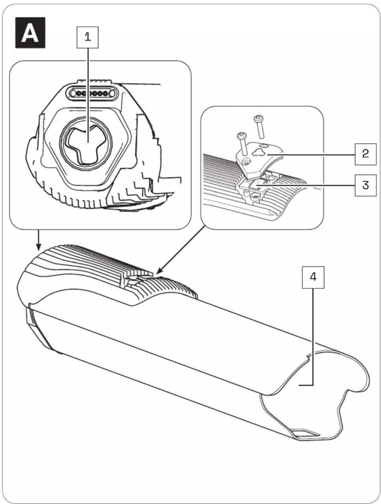
Part designations
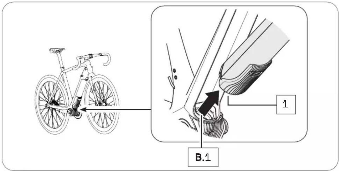
1 → Interface (bottom bracket)
2 → USB Cap
3 → USB port
4 → Battery holder
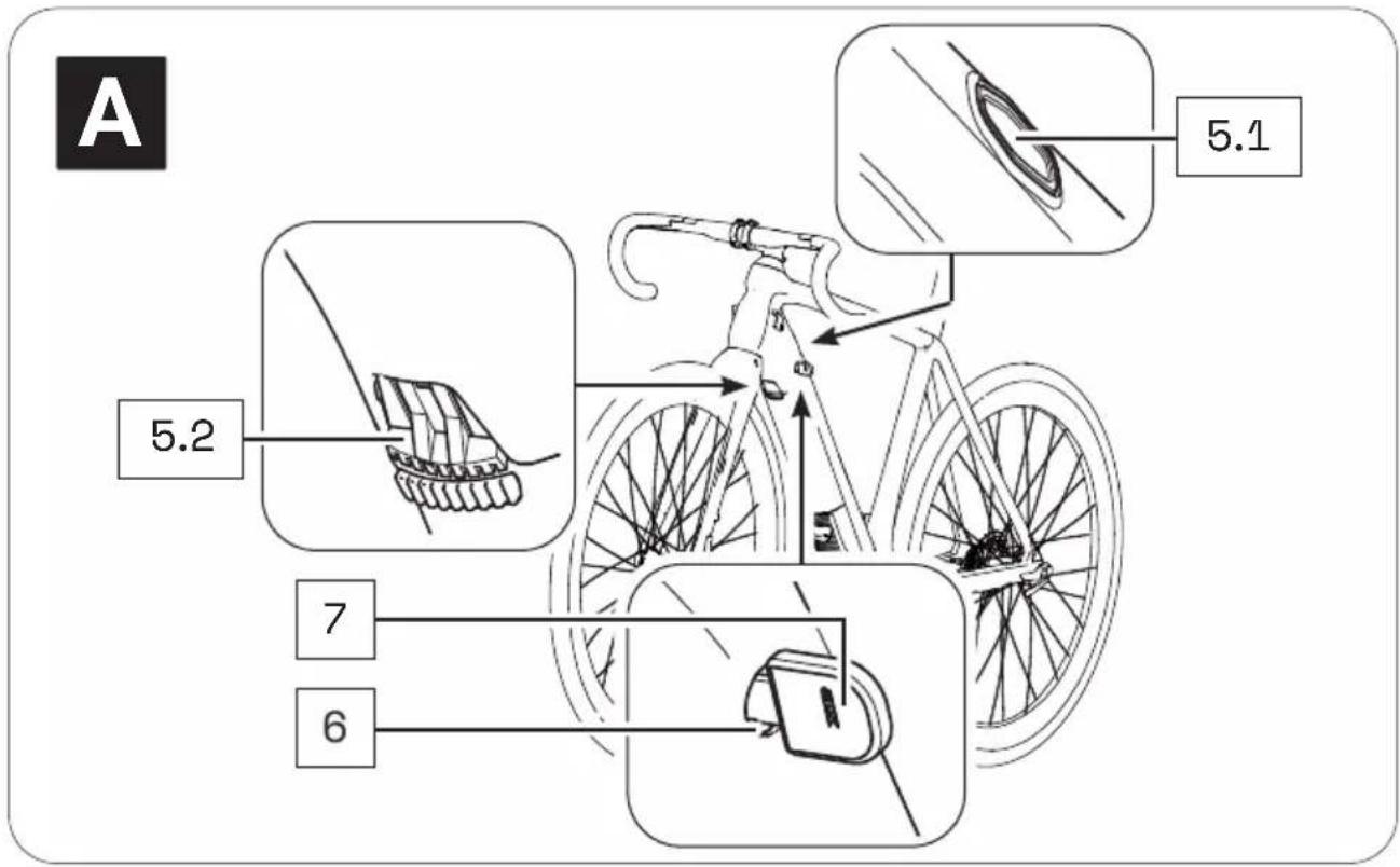
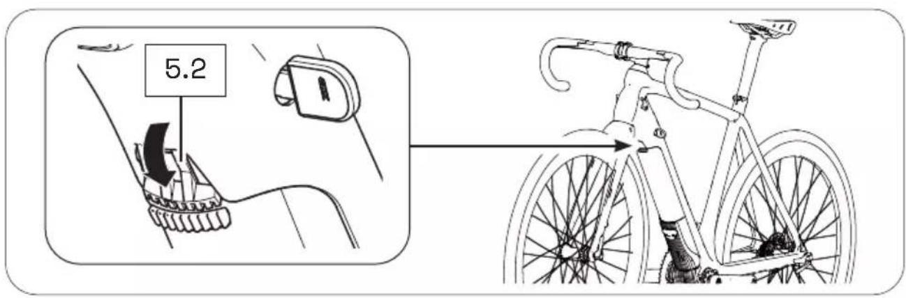
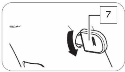
5 → Pushbutton (5.1)*/locking lever (5.2)*
6 → Cylinder lock**
7 → Key**
* The locker or mechanism for removing the drivepack is operated differently depending on the model:
With a push button located on the top of the down tube (Locker p) or with a locking lever located on the bottom of the down tube (Locker pX).
In this section you may find different illustrations and descriptions next to each other.
** The cylinder lock (incl. key) is a model-dependent installed part that may not be present on your e-bike.

The numbering 1–7 within this section refers to the individual parts of the components A (Drivepack).
Individual parts of other components illustrated within this section are additionally marked with the corresponding component letter.
14 TECHNICAL DATA
| TECHNICAL DATA ON THE DRIVEPACK | |
| Continuous rated power | → 250 W |
| Power, max. | → 400 W |
| Nominal voltage | → 36 V |
| Protection type | → IP54 |
| Weight, approx. | → 4.2 lbs (1.94 kg) |
| Operating temperature | → 23 °F to 104 °F (-5 °C to +40 °C) (ambient temperature) |
| Storage temperature (< 1 month) | → 5 °F to 140 °F (-15 °C to 60 °C) |
| Storage temperature (> 1 month) | → 5 °F to 77 °F (-15 °C to 25 °C) |
15 USING DRIVEPACK
15.1 Mounting the drivepack on the e-bike
- Place the drivepack with the free interface for the bottom bracket in front of the corresponding interface on the bottom bracket.
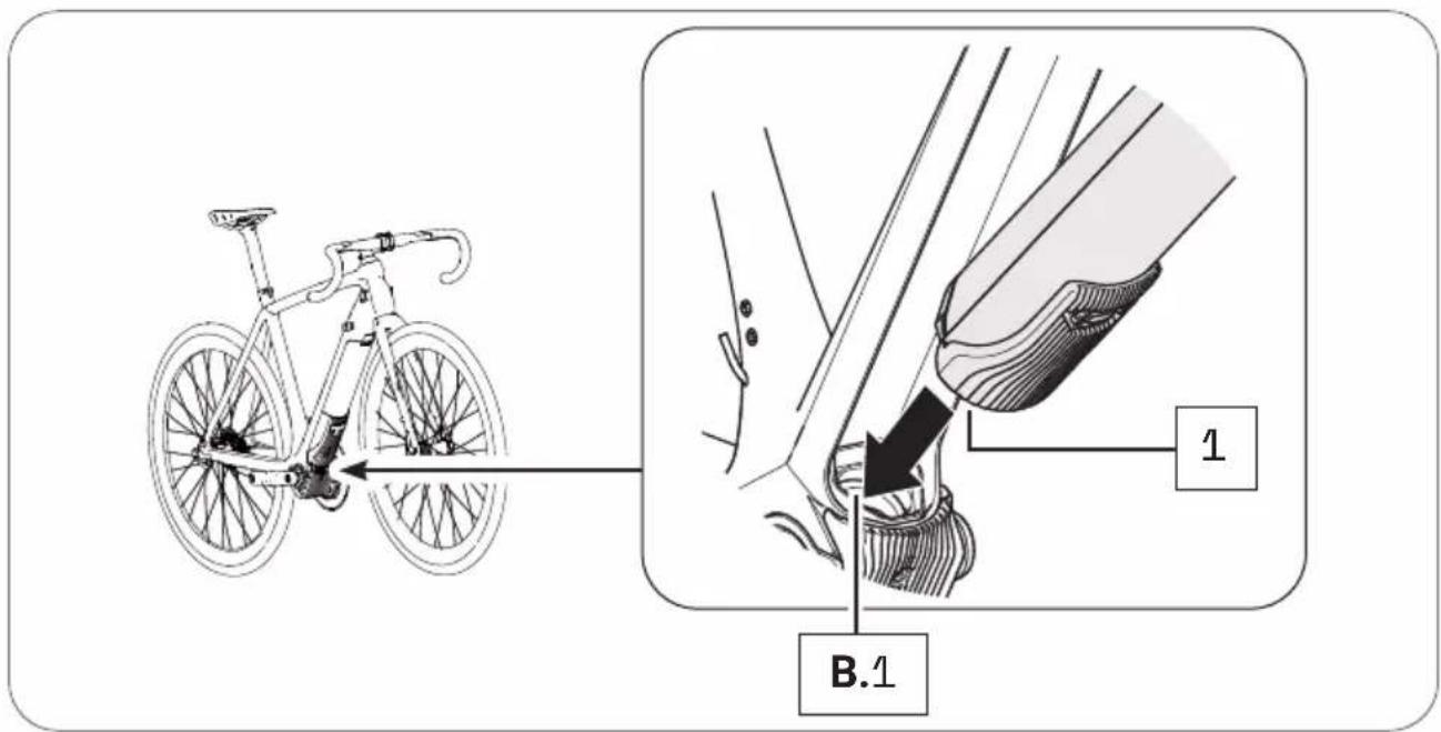
- Swing the upper end of the drivepack into the down tube of the e-bike. When you have inserted the drivepack correctly and completely into the down tube, the locking mechanism built into the down tube automatically engages in the motor mount and locks the drivepack in the correct position (you hear a click).
The push button or locking lever also moves automatically into the closed position.
- Check the drivepack makes a tight fit.
If the drivepack does not lock, pull it out again if necessary and then try to insert it again. Do not use the drive system if the drive unit cannot be locked. In this case, contact an authorized specialist to have the fault rectified.
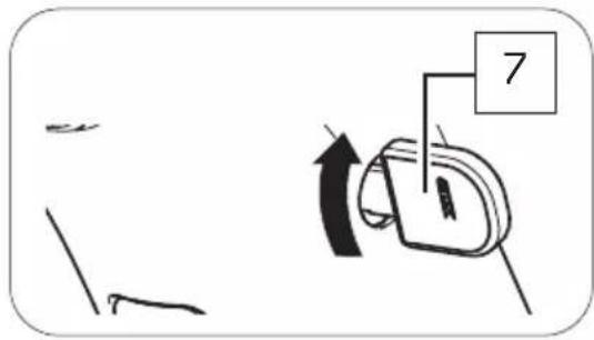
15.2 Remove drivepack from e-bike
WARNING
Risk of burns!
The radiator in the drivepack can become very hot during operation so that you can burn yourself on it.
▶ Let the drivepack to cool down completely before touching the drivepack.

If you press the drivepack firmly against the frame before pressing the push button or releasing the locking lever, it will be easier to release the drivepack from the locking device on the frame when removing it.
-
Secure the drivepack with one hand.
-
Press the push button down with the other hand to release the drivepack from the lock.
or
Move the locking lever upwards as far as possible to release the drivepack from the lock.
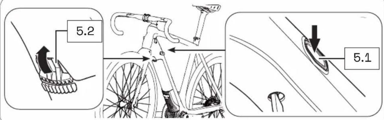
- Press and hold down the push button and carefully lower the drivepack out of its holder in the down tube.
The locking lever automatically remains in the open position.
- Remove the drivepack from the front of the interface on the bottom bracket.
1 5.3 Secure/lock drivepack from e-bike
Depending on the bicycle manufacturer, a cylinder lock is integrated into the frame of your e-bike, which you can use to lock the drivepack mounted on the e-bike and thus secure it against theft etc.
- If necessary, make sure that the drivepack is correctly attached to the e-bike.
- Insert the key into the cylinder lock, if necessary.
- Turn the key 90° counterclockwise to lock the drivepack to the e-bike.
- Remove the key from the cylinder lock.
If you want to unlock the drivepack again:
- Insert the key into the cylinder lock.
- Turn the key 90° clockwise to unlock the drivepack on the e-bike.
BOTTOM BRACKET
16 DETAILED VIEW & PART DESIGNATIONS: BOTTOM BRACKET
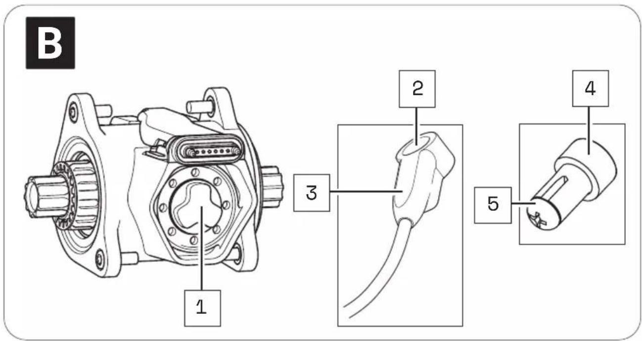
Part designations
1 → Interface (drivepack)
2 → Speed Sensor
3 → Marking (alignment spoke magnet/speed sensor)
4 → Spoke Magnet
5 → Fixing screw (spoke magnet)

The numbering 1-5 within this section refers to the individual parts of the components B (Bottom Bracket).
17 TECHNICAL DATA
| TECHNICAL DATA ON THE BOTTOM BRACKET | |
| Support torque, max. | → 55 Nm |
| Q factor, min. (without crank arms) | → 5.31" (135 mm) |
| Chain line | → 1.92",2.05" (49 mm, 52 mm) |
| Protection type | → IP54 |
| Weight, approx. | → 2.9 (1.3 kg) |
| Operating temperature | → 23 °F to 104 °F (-5 °C to +40 °C)(ambient temperature) |
| Storage temperature (< 1 month) | → 5 °F to 140 °F (-15 °C to 60 °C) |
| Storage temperature (> 1 month) | → 5 °F to 77 °F (-15 °C to 25 °C) |
18 USING BOTTOM BRACKET
The bottom bracket is already mounted when your e-bike is delivered. You must not make any changes to the bottom bracket yourself, as this could impair the safety and function of the drive system.
Only the speed sensor connected to the bottom bracket and the corresponding spoke magnet may have to be aligned correctly.
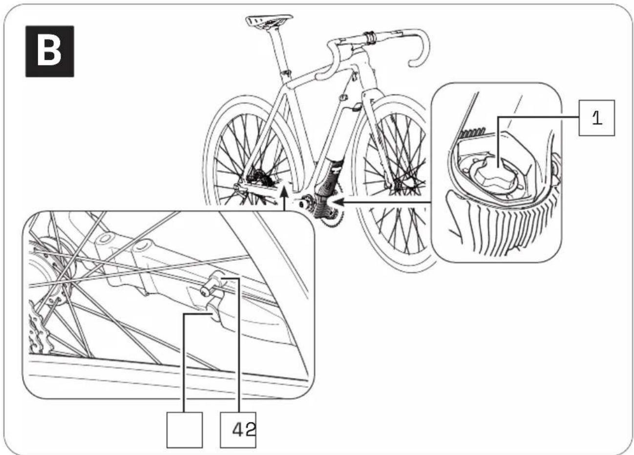
18.1 Correct position/alignment
For the drive system to function correctly, the speed sensor and spoke magnet must be correctly mounted and aligned on the rear wheel.
- The distance between the marking on the speed sensor and the spoke magnet must be in the range of 0.16–0.59" (4-15 mm).

If the distance between speed sensor and spoke magnet is outside the specified range or the speed sensor is not correctly connected, the drive system operates in "Soft Fault" fault mode.
→ More detailed information can be found in chapter 22.1 "Status display" or in chapter 26.1 "Status display".
NOTICE
Risk of damage!
If the spoke magnet and speed sensor are too close to each other and touch each other, the two parts may be damaged and may have to be replaced.
The spoke magnet must be positioned on the spoke so that it can move freely past the speed sensor at the marking level.
18.2 Correcting incorrect position/alignment
If you notice that the drive system is in "Soft Fault" fault mode because the speed sensor and spoke magnet are not correctly aligned, proceed as follows:
- Using a screwdriver, carefully loosen the fixing screw on the spoke magnet.
- To set the correct distance between the mark on the speed sensor and the spoke magnet:
- Move the spoke magnet vertically on its spoke (up/down), if necessary.
- Turn the spoke magnet around its own axis if necessary.
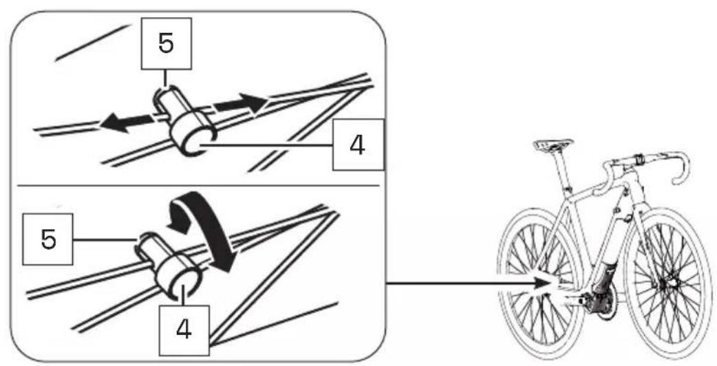
- If the problem cannot be solved, do not use the e-bike but contact an authorized specialist to have the fault rectified.
REMOTE
19 MODEL VARIANTS OF THE REMOTE
Depending on the model, you operate your drive system using the Remote b, Remote fX or Remote bX.
Since the model variants differ both visually and in their handling, the models within this section are described separately in Chapters 20–23 (Remote b) and 24–27 (Remote fX and Remote bX).
▶ Note the chapters 20–23 within this section - if your e-bike is equipped with the Remote b.
or
▶ Note the chapters 24–27 within this section - if your e-bike is equipped with the Remote fX or Remote bX.
20 DETAILED VIEW & PART DESIGNATIONS: REMOTE b
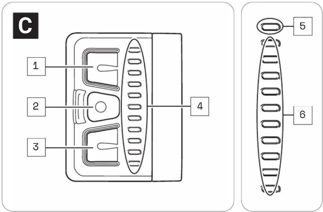

Part designations
1 → Upper button
2 → Center button
3 → Bottom button
4 → LED display
5 → Status display
6 → Display of charging level/support level
7 → Fixing screw remote

The numbering 1-7 within this section refers to the individual parts of the components C (Remote b).
Individual parts of other components illustrated within this section are additionally marked with the corresponding component letter.
21 TECHNICAL DATA REMOTE b
| TECHNICAL DATA ON THE REMOTE | |
| Protection type | → IP54 |
| Weight, approx. | → 0.185 lbs (0.085 kg) |
| Operating temperature | → 23 °F to 104 °F (-5 °C to +40 °C)(ambient temperature) |
| Storage temperature (< 1 month) | → 5 °F to 140 °F (-15 °C to 60 °C) |
| Storage temperature (> 1 month) | → 5 °F to 77 °F (-15 °C to 25 °C) |
22 DISPLAYS ON THE REMOTE b
The LED display on the Remote b consists of 11 LEDs.
- The upper LED serves as a status indicator, informing you of the status of your e-bike.
- The remaining 10 LEDs indicate the charge level and the support level of the pedal support set.
22.1 Status display
The status display indicates a status change or an existing fault. The status indicator does not light up if no fault is detected. Depending on which status is displayed, the LEDs light up in different colors.
The status display:
- flashes green = "Ready for operation"
After successful installation of the drivepack in the e-bike, the status indicator flashes green briefly to indicate that you can now switch on the drive system using the Remote b.
- lights up permanently green = "Bluetooth® device paired"
If you have paired a mobile end device (e.g. your smartphone) with the remote via the Bluetooth® function, the status indicator lights up permanently green as long as the Bluetooth® connection between the two devices exists.
- lights up yellow = "Soft Fault"
When a "Soft Fault" occurs, the status indicator lights up yellow. The drive system signals that a temporary or non-critical fault is present, which in most cases leads to a loss of power.
If a "soft fault" occurs, you can continue riding your e-bike, but Fazua strongly advises against doing so in order to avoid further damage to the drive system or e-bike.
- lights up red = "Hard Fault"
When a "Hard Fault" occurs, the status indicator lights up red. If a "hard fault" occurs on your e-bike, the e-bike can no longer be operated and must be serviced.
22.2 Display of charging level/support level
The charge/support level indicator shows two parameters.
• The battery charge level indicator:
The charge level of the battery can be read from the number of illuminated LEDs. Each of the 10 LEDs represents 10 % of the total charging capacity. When the battery is fully charged, all 10 LEDs light up. If the battery is flat, no LEDs light up.
• The selected support level of the pedal support:
Each support level is assigned a color, i.e. the color of the LEDs on the display indicates the currently set support level.
→ More detailed information can be found in chapter 23.3 "Levels of support".
23 USING REMOTE b
WARNING
Danger due to distraction during operation!
If you are distracted by the use of the Remote b while riding, accidents and serious injury may result.
Before using your e-bike for the first time, familiarize yourself with the functions and handling of your remote away from road traffic.
▶ Do not use the Remote b while riding if it distracts you.
23.1 Switching the drive system on and off
▶ Switch on the drive system using the Remote b by pressing one of the three buttons.
▶ Turn off the drive system using the Remote b by pressing and holding the center button for 2 seconds.
23.2 Setting the pedal support
With the help of the Remote b you can set the desired support level at any time - even while riding.
▶ Press the upper button on the Remote b to switch to the next higher support level.
▶ Press the lower button on the Remote b to switch to the next lower support level.
23.3 Levels of support
no support
• The LEDs of the display on the Remote b light up white.
- You ride without electric pedal assistance (as with a conventional bicycle).
Support level "Breeze"
• The LED of the display on the Remote b lights up green.
- You ride with low but effective support for maximum range.
Support level "River"
• The LEDs of the display on the Remote b light up blue.
- You ride with reliable support for most applications.
Support level "Rocket
• The LEDs of the display on the Remote b light up pink.
- You ride with maximum support for very demanding trips.

The maximum motor power for all support levels can be individually configured by the manufacturer of your e-bike.
▶ Also note the manufacturer's specifications for your e-bike to determine how high the maximum motor power is for your e-bike.
| OVERVIEW TABLE "SUPPORT LEVELS" | ||
| Support level Color max. motor power | ||
| none white 0 | W | |
| Breeze green 400 W* | ||
| River blue 400 W* | ||
| Rocket pink 400 W* | ||
* The values given here are the "theoretical" maximum motor power.
23.4 "Pushing support" mode
WARNING
Danger from accidental starting!
Starting the drive system in unsuitable situations can result in accidents and serious injury.
▶ Use the "Pushing support" function only when pushing the e-bike.
When the pushing support is activated, hold the e-bike securely with both hands and make sure that the wheels are in contact with the ground.
CAUTION
Risk of injury!
If you push the e-bike with the pushing support activated, the pedals rotate slowly and you may be injured.
▶ Be careful not to injure yourself on the rotating pedals when using the "Pushing support" function.
23.4.1 General information about the mode
The pushing support facilitates the pushing of the e-bike.
In the "Pushing support" mode your e-bike can reach a speed of up to 3.73mph (6 km/h) depending on the gear selected.
You can slow down the speed of the e-bike to your walking speed by holding or restraining the e-bike.
The pushing support is automatically disabled if:
• You release the lower button,
• the wheels on the e-bike are locked,
• the e-bike reaches a speed of more than 3.73 mph (6 km/h).
23.4.2 Switching the "Pushing support" mode on and off
- Use the remote to set the support level to "none".
- Press and hold the lower button on the Remote b to activate the pushing support.
After 2 seconds the pushing support is activated and sets the e-bike in motion as long as you keep the button pressed.
- Guide the e-bike with both hands and, if necessary, brake the speed of the e-bike to your own walking speed by holding or restraining the e-bike while pushing.
- Switch off the pushing support by releasing the lower button.
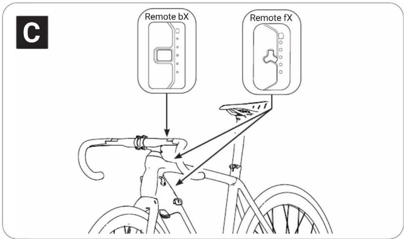
24 DETAILED VIEW & PART DESIGNATIONS: REMOTE fX AND REMOTE bX

The Remotes fX and bX differ in their attachment point:
→ Remote fX is located on the frame (top and bottom tube),
→ Remote bX is located on the handlebar.
flowchart
graph TD
    subgraph_Remote_fX["Remote fX"]
        A1["1"] --> B2["2"]
        B2 --> C3["3"]
        C3 --> D4["4"]
        D4 --> E5["5"]
    end
    subgraph_Remote_bX["Remote bX"]
        A2["1"] --> B2
        B2 --> C3
        C3 --> D4
        D4 --> E5
        E5 --> F5["5"]
        E5 --> G7["7"]
        E5 --> H6["6"]
    end
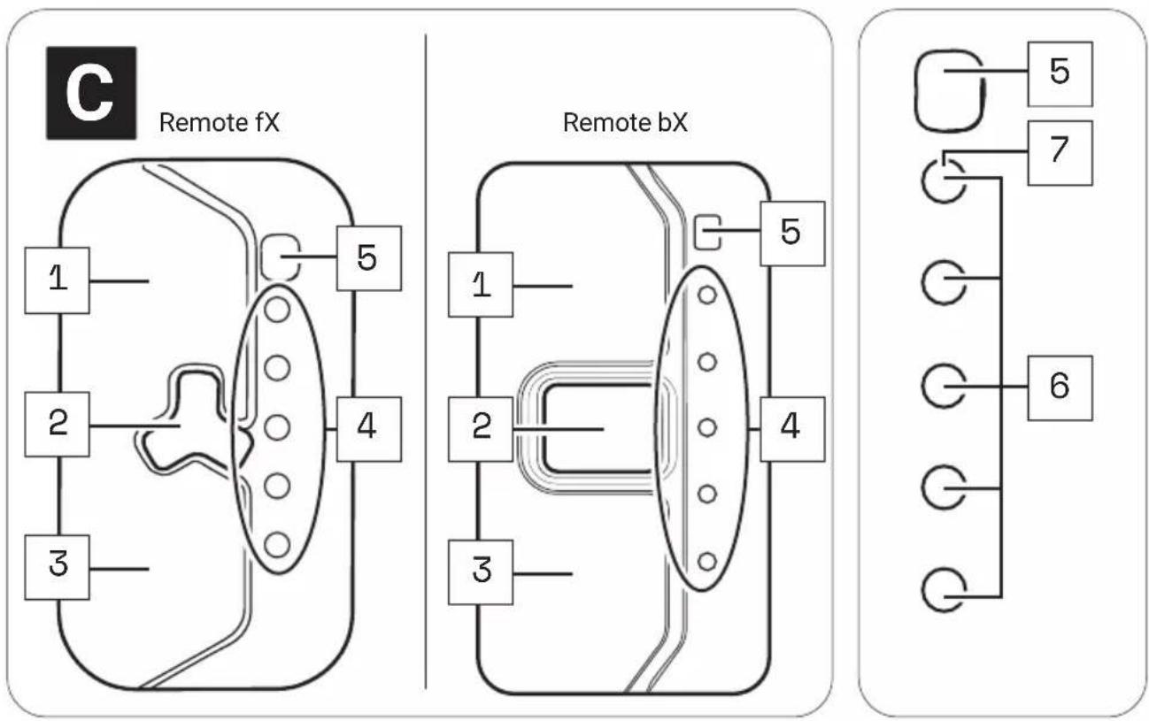
Part designations
1 → Upper touch sensor
2 → Center button
3 → Lower touch sensor
4 → LED display
5 → Brightness sensor
6 → Display of charging level/support level
7 → Status display

The numbering 1-7 within this section refers to the individual parts of the components C (Remote fX and Remote bX).
Individual parts of other components illustrated within this section are additionally marked with the corresponding component letter.
25 TECHNICAL DATA REMOTE fX AND REMOTE bX
| TECHNICAL DATA ON THE REMOTE | |
| Degree of protection (in assembled condition) | → IP54 |
| Weight, approx. | → 0.106 lbs (0.048 kg) |
| Operating temperature | → 23 °F to 104 °F (-5 °C to +40 °C) (ambient temperature) |
| Storage temperature (< 1 month) | → 5 °F to 140 °F (-15 °C to 60 °C) |
| Storage temperature (> 1 month) | → 5 °F to 77 °F (-15 °C to 25 °C) |
26 DISPLAYS ON THE REMOTE fX AND REMOTE bX
The LED display on the Remote fX / Remote bX consists of 5 LEDs.
- All five LEDs together serve as a display for the charge level and the support level of the pedal support.
- The upper of the five LEDs also serves as a status indicator, informing you about the status of your e-bike.
2 6.1 Status display
The status display indicates a status change or an existing fault. If no fault is detected, the status indicator LED will act as one of the five LEDs to indicate the charge level or set support level.
Depending on which status is displayed, the LED of the status indicator lights up in different colors.
The status display:
- flashes green = "Ready for operation"
After successful installation of the drivepack in the e-bike, the status indicator flashes green briefly to indicate that you can now switch on the drive system using the Remote fX / Remote bX.
- flashes yellow = "Soft Fault"
When a "Soft Fault" occurs, the status indicator flashes yellow. The drive system signals that a temporary or non-critical fault is present, which in most cases leads to a loss of power.
If a "soft fault" occurs, you can continue riding your e-bike, but Fazua strongly advises against doing so in order to avoid further damage to the drive system or e-bike.
- flashes red = "Hard Fault"
When a "Hard Fault" occurs, the status display flashes red. If a "hard fault" occurs on your e-bike, the e-bike can no longer be operated and must be serviced.
2 6.2 Display of charging level/support level
The charge/support level indicator shows two parameters.
• The battery charge level indicator:
The charge level of the battery can be read from the number of illuminated LEDs. Each of the 5 LEDs represents 20 % of the total charging capacity. When the battery is fully charged, all 5 LEDs light up.
If the battery is flat, the upper LED of the status indicator lights up white or no LED lights up.
• The selected support level of the pedal support:
Each support level is assigned a color, i.e. the color of the LEDs on the display indicates the currently set support level.
→ More detailed information can be found in chapter 27.3 "Levels of support".
27 USING REMOTE fX AND REMOTE bX
WARNING
Danger due to distraction during operation!
If you are distracted by the use of the Remote fX / Remote bX while riding, accidents and serious injury may result.
Before using your e-bike for the first time, familiarize yourself with the functions and handling of your Remote fX / Remote bX away from road traffic.
▶ Do not use the Remote fX / Remote bX while riding if it distracts you.
2 7. 1 Switching the drive system on and off
▶ Switch on the drive system using the Remote fX / Remote bX by pressing the center button.
▶ Turn off the drive system using the Remote fX / Remote bX by pressing and holding the center button for 1 second.
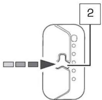
flowchart
graph TD
    A["Input"] --> B["Processing Step"]
    B --> C["Output"]
    style A fill:#f9f,stroke:#333
    style B fill:#ccf,stroke:#333
    style C fill:#cfc,stroke:#333
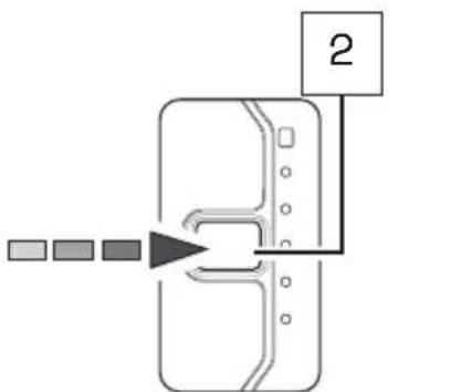
flowchart
graph TD
    A["Input 1"] --> B["Process Step"]
    B --> C["Output 2"]
Remote bXRemote fX
2 7. 2 Setting the pedal support
With the help of the Remote fX / Remote bX you can set the desired support level at any time - even while riding.
Tap the upper touch sensor on the Remote fX / Remote bX to switch to the next higher support level.
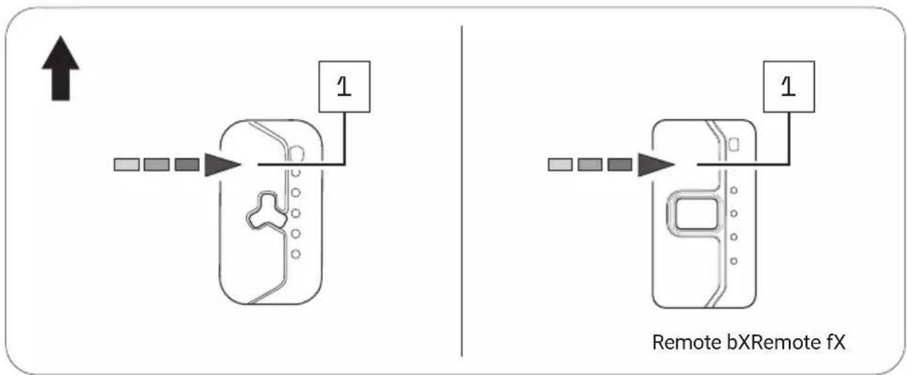
flowchart
graph TD
    A["↑"] --> B["Device 1"]
    B --> C["Device 2"]
    C --> D["Device 3"]
    D --> E["Device 4"]
    E --> F["Device 5"]
    F --> G["Device 6"]
    G --> H["Device 7"]
    H --> I["Device 8"]
    I --> J["Device 9"]
    J --> K["Device 10"]
    style A fill:#f9f,stroke:#333
    style K fill:#bbf,stroke:#333
Tap the lower touch sensor on the Remote fX / Remote bX to move to the next lower support level.
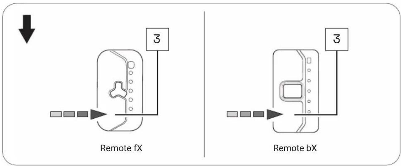
flowchart
graph TD
    A["Remote fX"] --> B["Device with 3 pins"]
    C["Remote bX"] --> D["Device with 3 pins"]
    style A fill:#f9f,stroke:#333
    style C fill:#f9f,stroke:#333
    style B fill:#ccf,stroke:#333
    style D fill:#ccf,stroke:#333

When driving in rain mode, use the center button to set the desired support level.
→ More detailed information can be found in chapter 27.5 "Rain mode".
2 7. 3 Levels of support
No support (white)
- The LEDs of the display on the Remote fX / Remote bX light up white.
- You ride without electric pedal assistance (as with a conventional bicycle).
Support level "Breeze"
- The LED of the display on the Remote fX / Remote bX lights up green.
- You ride with low but effective support for maximum range.
Support level "River"
• The LEDs of the display on the Remote fX / Remote bX light up blue.
- You ride with reliable support for most applications.
Support level "Rocket
- The LEDs of the display on the Remote fX / Remote bX light up pink.
- You ride with maximum support for very demanding trips.

The maximum motor power for all support levels can be individually configured by the manufacturer of your e-bike.
▶ Also note the manufacturer's specifications for your e-bike to determine how high the maximum motor power is for your e-bike.
| OVERVIEW TABLE "SUPPORT LEVELS" | ||
| Support level Color max. motor power | ||
| none white 0 | W | |
| Breeze green 400 W* | ||
| River | blue | 400 W* |
| Rocket | pink | 400 W* |
* The values given here are the "theoretical" maximum motor power.
2 7. 4 Restart drive system
▶ Press and hold the center button for 8 seconds to fully shut down your drive system: All LEDs go out.
When the drive system is ready to be switched on again, the status indicator flashes green: Now you can restart your drive system as usual.
27.5 Rain mode
The rain mode prevents rain drops from unintentionally adjusting the support level of your e-bike.
If you have activated the rain mode, use the center button to set the desired support level:
-
Activate the rain mode by holding down the center button for 2 seconds. A short blue LED animation appears.
-
In rain mode, press the center button 1x briefly to switch to the next higher support level.
By briefly pressing the center button again, you can switch to the next higher support level in the following order:
no support → "Breeze → "River → "Rocket" → no support etc.
- To return from the rain mode to the regular operating mode, press and hold the center button again for 2 seconds.
2 7. 6 Switching bicycle lighting on and off

Depending on the model, your e-bike has a bicycle light that you can switch on and off using the Remote fX / Remote bX.
IMPORTANT: The bicycle lighting can only be switched on and off in regular operating mode using the Remote fX / Remote bX, not in rain mode!
- If necessary, deactivate the rain mode by pressing and holding the center button for about 2 seconds.
- Press the center button once briefly to turn on the bicycle lights.
- Press the center button again once briefly to turn off the bicycle lights.
2 7. 7 Bluetooth connectivity
You can connect your cell phone to your drive system via the Fazua Rider App. If the connection has been established successfully, the LEDs on the Remote fX / Remote bX flash 3× blue.
BATTERY
28 MODEL VARIANTS OF THE BATTERY
Depending on the model, your drive system is powered by the Battery 250 or Battery 250 X.
Since the two model variants differ in appearance, you may find different model-dependent illustrations next to each other in this section.
Different handling of the model variants after automatic switch-off of the battery:
The Battery 250 switches off automatically if the e-bike has not moved for 8 hours and no button or touch sensor has been pressed on the remote.
The Battery 250 X switches off automatically if the e-bike has not moved for 1 hours and no button or touch sensor has been pressed on the remote.
▶ Press the on/off button once on the battery to switch the Battery 250 or Battery 250 X on again ("wake up").

Both model variants have the function for displaying the "state of health" (SOH) of the battery by double-clicking on the on/off button on the battery.
The SOH is displayed in 20 % increments (similar to the battery charge indicator): If all five LED's are flashing, the battery has a SOH of 100%, if four LED's are flashing 80%, etc.
29 DETAILED VIEW & PART DESIGNATIONS: BATTERY
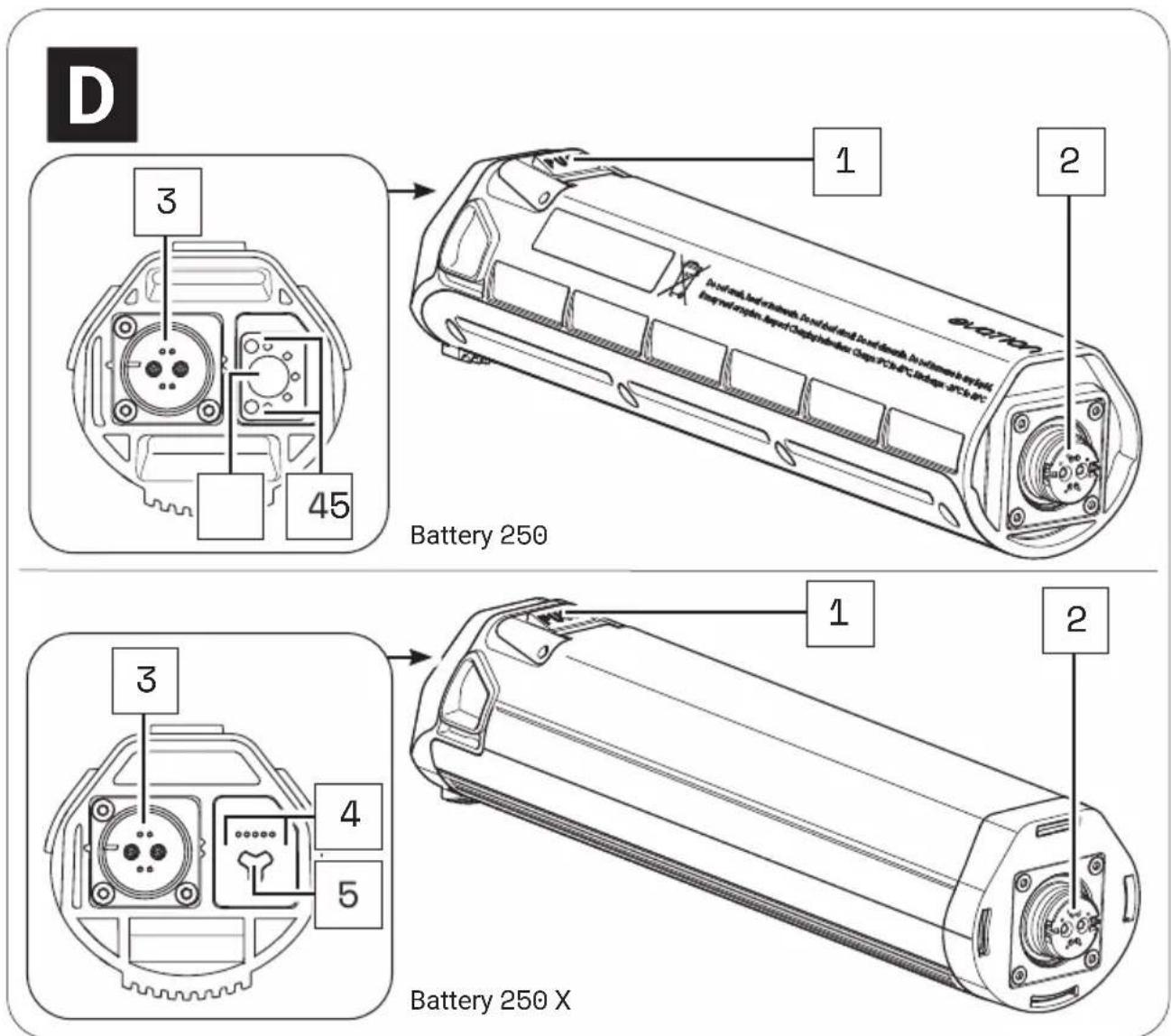
Part designations
1 → Pushbutton (battery lock)
2 → Interface (drivepack)
3 → Charging socket
4 → Charge level indicator*
5 → On/off button
* The charge level indicator of the Battery 250 X is only visible when the corresponding LEDs are lit, but not, for example, when the battery is switched off.

The numbering 1–5 within this section refers to the individual parts of the components D (battery).
Individual parts of other components illustrated within this section are additionally marked with the corresponding component letter.
30 TECHNICAL DATA
| TECHNICAL DATA ON THE BATTERY | |
| Nominal voltage | → 36 V |
| Nominal capacity | → 7 Ah |
| Power | → 252 Wh |
| Protection type | → IP54 |
| Weight, approx. | → 3.1 lbs (1.4 kg) |
| Operating temperature | → 23 °F to 104 °F (-5 °C to +40 °C)(ambient temperature) |
| Storage temperature (< 1 month)* | → 5 °F to 140 °F (-15 °C to +60 °C) |
| Storage temperature (> 1 month)* | → 5 °F to 77 °F (-15 °C to 25 °C) |
* Please also note the information on the storage time-dependent temperature ranges for the battery in chapter "Storage and transport".
31 USING THE BATTERY
31.1 Checking and switching on battery
DANGER
Risk of explosion and fire!
A damaged or dirty battery may explode and/or cause a fire.
▶ Never insert a damaged battery into the drivepack.
▶ Check the battery for visible damage, such as cracks or burn marks, before each insertion.
▶ Make sure that the interfaces on the battery are free of dirt before using it.

You can query the charge level of the battery at any time, by pressing the on/off button 1x: The number of illuminated LEDs indicate the charge level. Thus each illuminated LED corresponds to 20% of the total charging capacity. When the battery is fully charged, all 5 LEDs light up.
-
Check the battery for visible damage (visual check).
-
Press the on/off button on the battery once to turn on the battery:
The LEDs of the charge level indicator next to the on/off button light up and indicate the current charge level of the battery.
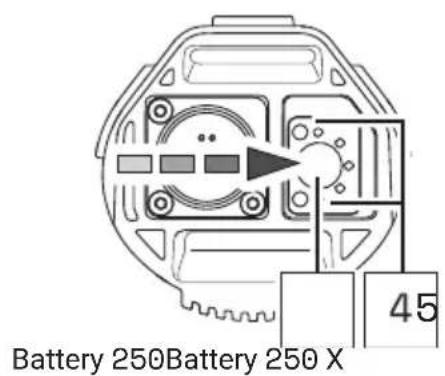
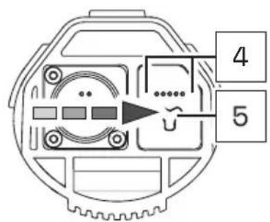
If none of the LEDs on the charge indicator light up after pressing the on/off button, this indicates that the battery is damaged.
In this case, do not insert the battery into the drivepack, but contact an authorized specialist.
31.2 Inserting the battery into the drivepack
- Hold the drivepack with one hand and the battery with the other.
- Position the battery with the interface forwards in front of the empty battery receptacle and align it so that the battery lock push button is on the same side as the corresponding opening on the drivepack.

The battery is designed so that it can only be inserted into the battery receptacle when correctly aligned.
So if you have problems inserting the battery into the battery holder, it may be because you have not aligned the battery correctly.
Therefore, in this case, first check the correct alignment of the battery and try inserting it again.
If the battery cannot be inserted into the battery receptacle despite correct alignment, this may indicate that one of the components is damaged.
Do not use the drive system if the battery cannot be inserted into the battery holder, but contact an authorized specialist.
- Carefully insert the battery as far as possible into the battery holder of the drivepack until you hear a click.
When you have inserted the battery correctly and completely into the battery holder, the push button on the battery slides into the corresponding opening on the drivepack and locks the battery in place.
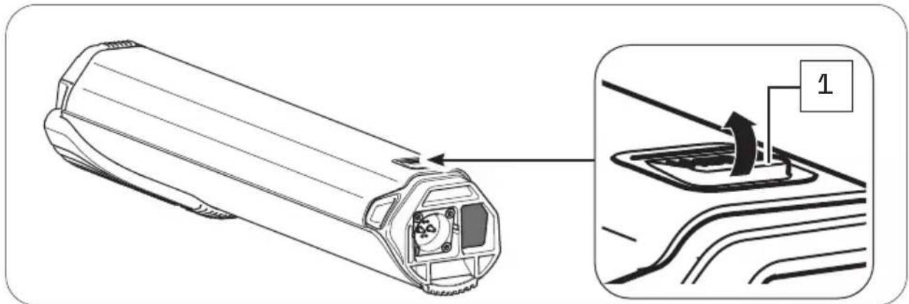
If the battery does not lock, pull it out again if necessary, make sure that there is no dirt inside the drivepack to obstruct insertion, and then try inserting the battery again. Do not use the drive system if the battery cannot be locked. In this case, contact an authorized specialist to have the fault rectified.
31.3 Removing the battery from the drivepack
CAUTION
Pinch risk!
You can pinch your fingers when removing the battery from the drivepack.
▶ When pressing the push button or removing the battery, be careful not to pinch your fingers.
- Hold the drivepack with one hand and secure the battery with the other.
- Press the push button as far as it will go to release the battery from the lock.
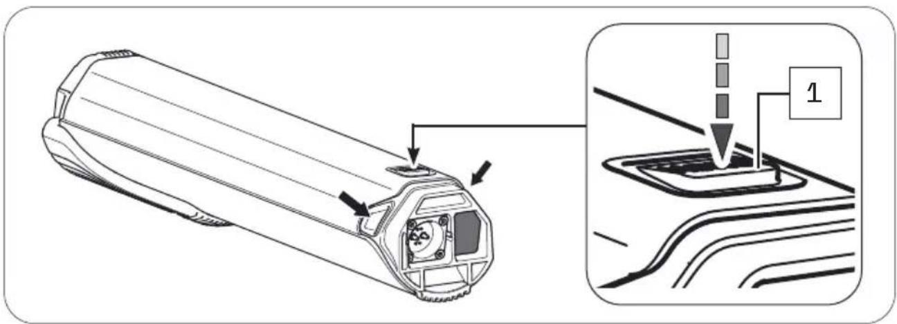
- Press and hold the push button, grasp the battery on the two handles and gently pull the battery out of the battery holder.
The two handles are located at the side of the upper battery end (see arrows).
31.4 Switching off the battery
▶ Turn off the battery by pressing and holding the on/off button.
31.5 Charging the battery
DANGER
Fire hazard due to incorrect handling!
If you handle the battery improperly or try to charge it with an incompatible charger you could cause a fire.
▶ To charge the battery, use only original and compatible evation chargers from Fazua.
The charger and battery heat up during charging, so keep away from combustible materials.
▶ Do not leave the battery and charger unattended during charging.
DANGER
Risk of electric shock!
Improper handling of the charger or incorrect mains connection may expose you and others to the risk of electric shock.
▶ Observe the instructions in section "Charger".
You can either leave the battery in the drivepack during charging or remove it from the drivepack and charge it separately. The charging process can also be interrupted at any time.
You cannot charge the battery if the temperature is outside the permissible charging temperature (14 °F to 140 °F (-10 °C to +60 °C)). This is not possible even if the battery is connected to the charger.
Charging is only possible again when the permissible charging temperature has been reached.
▶ Fully charge the battery prior to initial operation so that you can use the full capacity of the battery.
31.5.1 Connect battery to the charger
- Insert the charging plug into the charging socket on the battery. Since the charging plug is magnetically coded, it can only be plugged in in the intended position.
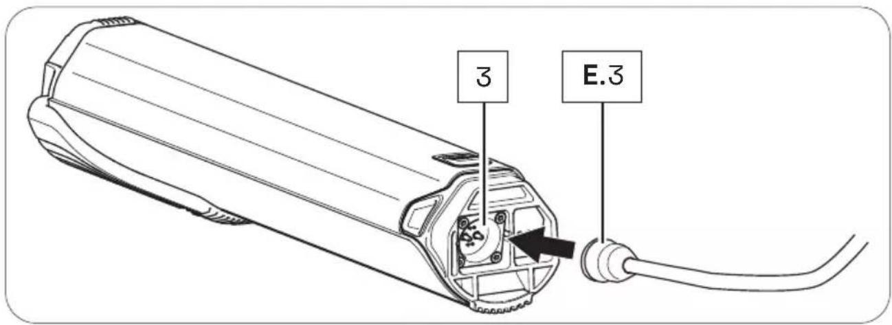
- Plug the power plug into a suitable wall outlet to establish the power connection.
The charging process starts automatically after connection to the mains.
31.5.2 Ending charging process
- Then disconnect the charger from the power grid by pulling the mains plug out of the socket.
- Disconnect the charger from the battery by pulling the charger plug out of the charging socket on the battery.
- Replace the drivepack with the battery correctly on the e-bike.
31.6 Charging process
Charging begins as soon as you have connected the charger's charger plug to the charger socket on the battery and the charger to the power supply.
The flashing LEDs on the battery charge indicator indicate that the battery is being charged.
3 1.7 Battery charge level indicator
As soon as you have switched on the battery, the charge status display automatically shows a start animation. Immediately afterwards, the LEDs briefly indicate the current charge level of the battery.
Depending on the charge level, the number of LEDs varies, with each LED representing 20 % of the capacity. If all five LEDs are lit, the battery is fully charged.
As soon as the battery is fully charged, the LEDs of the charge level indicator go out.
When the battery is switched on, press the on/off button on the battery to check the charge status, e.g. before or during a (longer) trip.
CHARGER
32 MODEL VARIANTS OF THE CHARGER
Depending on the model, you charge the battery of your drive system using the Charger A or the Charger S.
The two model variants differ in some respects visually and with regard to their technical data. You may therefore find different model-dependent illustrations or information in this section.
If none of the model variants is explicitly mentioned, the descriptions refer to all model elements.
33 DETAILED VIEW & PART DESIGNATIONS: CHARGER

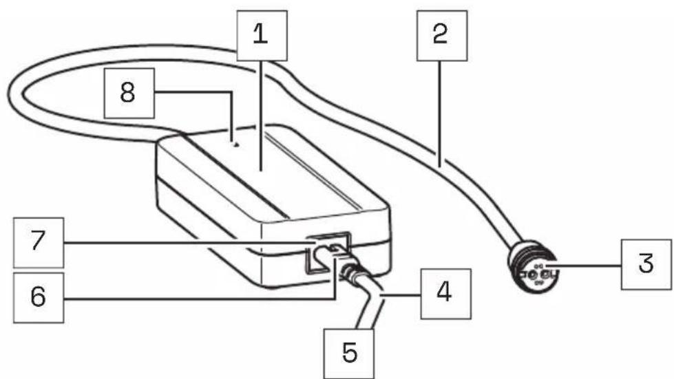
Charger A
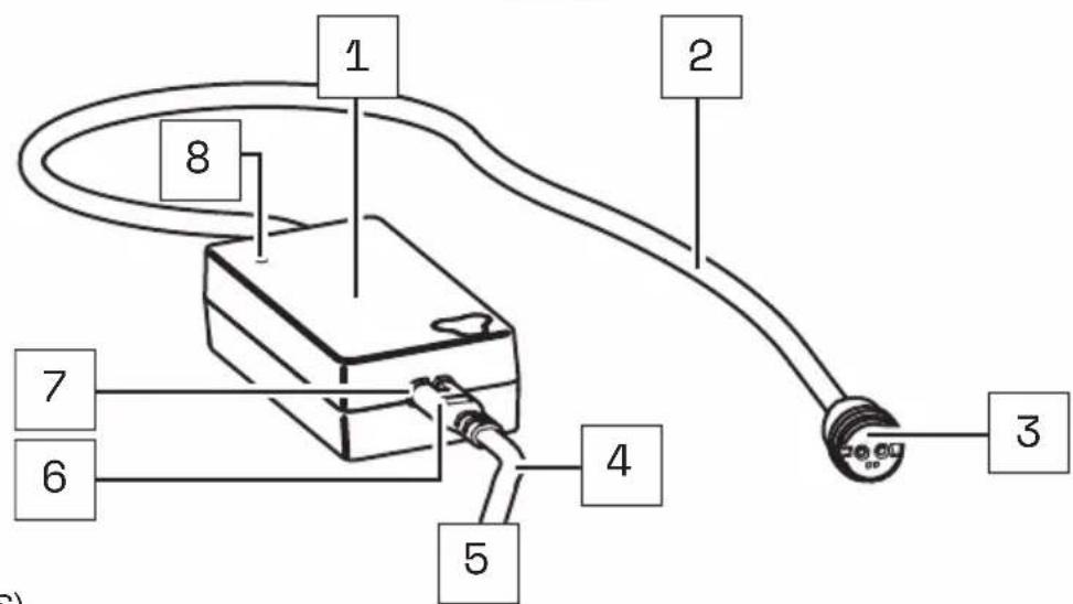
Charger S (EU/US)
Part designations
1 → Mains adapter
2 → Charging cable
3 → Charging plug
4 → Mains cable
5 → Mains plug (power supply)*
6 → Plug
7 → Mains socket
8 → LED display
* Different from country to country, therefore without illustration.

The numbering 1–8 within this section refers to the individual parts of the components E (charger).
Individual parts of other components illustrated within this section are additionally marked with the corresponding component letter.
34 TECHNICAL DATA
| TECHNICAL DATA ON THE CHARGER | |
| Nominal input voltage | 100-240 V AC (Charger A)→ 220-240 V AC (Charger S (EU))100-110 V AC (Charger S (US)) |
| Frequency | → 50/60 Hz |
| Charging current | → 2 A |
| Charging time, approx. | → 3.5 h |
| Protection class | → 2 [symbol: □] |
| Protection type | → IP54 |
| Weight, approx. | → 0.850 lbs (0.39 kg) |
| Operating temperature | → 32 °F to 113 (0°C to +45 °C) |
| Storage temperature | → 32 °F to 113 °F (0 °C to +45 °C) |
35 USING CHARGER
DANGER
Risk of electric shock and fire!
If you use a damaged charger you could expose yourself and others to the risk of an electric shock. If you use the charger improperly or with an incompatible battery you could cause a fire.
Therefore check all individual part for damage before using the charger.
▶ Never use a damaged charger.
▶ Only use the charger in dry indoor areas.
▶ Keep water or any liquids away from the charger or all individual parts of the charger.
The charger and battery heat up during charging, so keep away from combustible materials and do not leave the two components unattended during charging.
▶ During charging place the charger and battery on a well ventilated surface.
▶ Only use the charger to charge the original and compatible evation battery from Fazua. Never attempt to charge non-rechargeable batteries!
35.1 Prepare charger
- Take the power supply unit and the power cord with you.
- Plug the appliance plug of the mains cable into the mains socket on the power supply unit.
35.2 Connector charger to the battery
DANGER
Risk of electric shock!
If the mains connection is incorrect, you and others may be exposed to the risk of electric shock.
▶ First connect the charger to the battery before you connect the charger to the power supply.
▶ Only connect the charger to an easily accessible and properly installed earth contact outlet.
▶ Make sure that the mains voltage at the mains connection corresponds to the information on the charger.
- Plug the charger's charger plug into the charging socket on the battery.
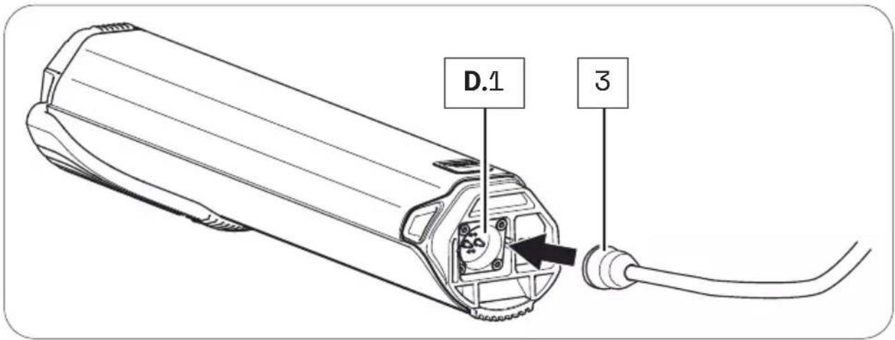
- Plug the power plug into a suitable wall outlet to establish the power connection.
The charging process starts automatically after connection to the mains. During the charging process, the LED indicator on the power supply unit lights up red and signals that the battery is being charged. When the color of the LED indicator changes to green, this signals that the battery is fully charged.
3 5.3 Unplug charger from battery
DANGER
Risk of electric shock!
If the mains connection is incorrect, you and others may be exposed to the risk of electric shock.
▶ First disconnect the charger from the power supply before you disconnect the charger from the battery.
- When charging is complete, unplug the charger from the outlet to disconnect it from the mains.
- Then disconnect the charger from the battery by pulling the charging plug out of the charging socket.
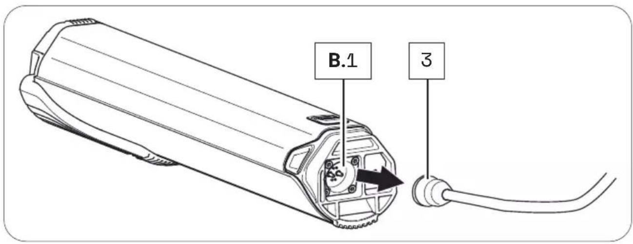
- Then disconnect the power cord from the AC adapter and keep the two parts of the charger separate from each other.

FAZUA
Fazua GmbH
natural_image
Technical line drawings of various electronic devices including a battery, switch, and display unit (no text or symbols present)
FAZUA
natural_image
Technical line drawing of a mechanical component with curved and straight sections (no text or symbols)natural_image
Technical line drawing of a mechanical gear assembly (no text or symbols)natural_image
Technical line drawing of a cylindrical electronic device with mounting holes and internal compartments (no text or symbols)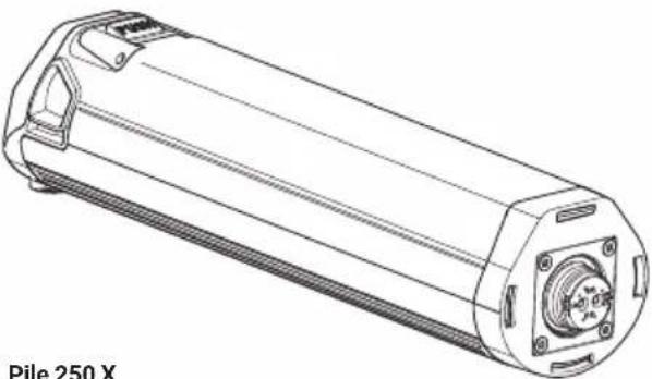
natural_image
Technical line drawing of a cylindrical electronic device with mounting flanges and a central hub (no text or symbols on the diagram itself)natural_image
Simple line drawing of a rectangular device connected to a terminal with a coiled cable (no text or symbols)natural_image
Simple line drawing of a rectangular device connected to a terminal with a curved cable (no text or symbols)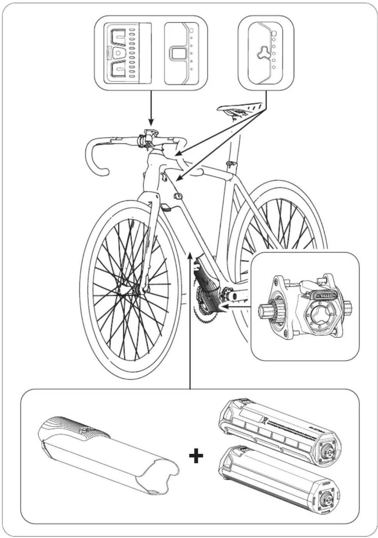
2 À PROPOS DE CE MANUEL
natural_image
Diagram of a device emitting particles from a fan, with a labeled component 'C' (no text or symbols on the diagram itself)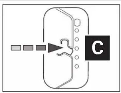
flowchart
graph TD
    A["Start"] --> B{Decision}
    B --> C["Label C"]
    style C fill:#000,stroke:#fff,color:#fff
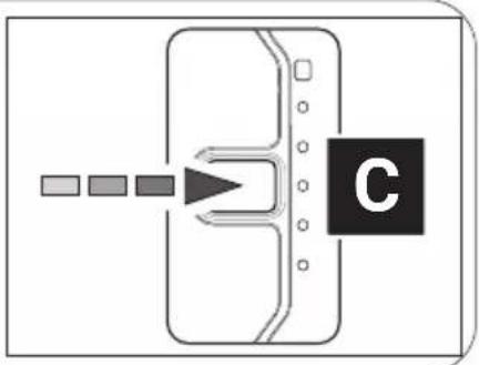
flowchart
graph TD
    A[" "] --> B[" "]
    B --> C[" "]
    C --> D[" "]
    D --> E[" "]
    E --> F[" "]
    style C fill:#000,stroke:#000,color:#fff
    style F fill:#000,stroke:#000,color:#fff
natural_image
Diagram of a device with a labeled component 'C' and directional arrow, no readable text or symbols present.natural_image
Technical illustration of a mechanical component with pins and a downward arrow indicating a process (no text or symbols present)18.1 Position/alignment correct
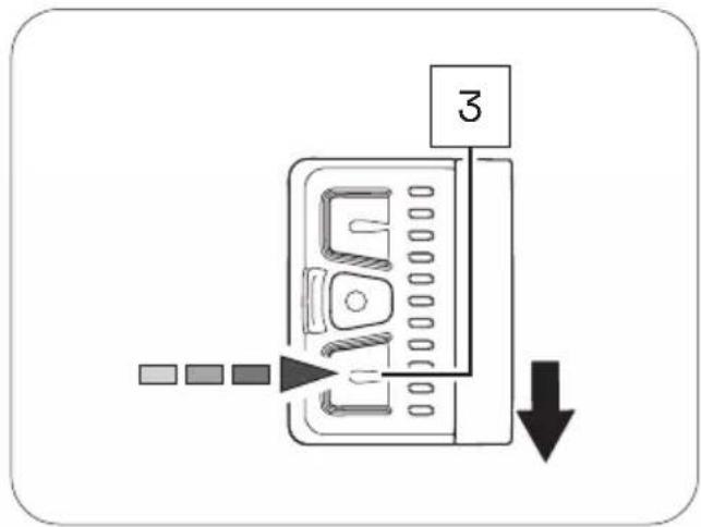
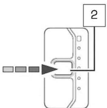
flowchart
graph TD
    A["Input 1"] --> B["Process Step"]
    B --> C["Output 2"]
natural_image
Technical line drawings of various electronic devices including a battery, switch, and display unit (no text or symbols present)
FAZUA
natural_image
Technical line drawing of a mechanical component with curved and straight sections (no text or symbols)B
natural_image
Technical line drawing of a mechanical assembly with gears and housing (no text or symbols)natural_image
Technical line drawing of a cylindrical electronic device with mounting holes and a central screw (no text or symbols on the diagram itself)natural_image
Line drawing of a Cargador S (UE/EE, UU.) device with cable and connector (no text or symbols on the diagram itself)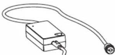
natural_image
Simple line drawing of a rectangular device connected to a terminal with a curved cable (no text or symbols)2 ACERCA DE ESTE MANUAL
flowchart
graph TD
    A["Input"] --> B["Device"]
    B --> C["C"]
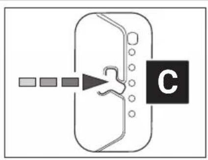
flowchart
graph TD
    A["Start"] --> B["Step 1"]
    B --> C["Step 2"]
    C --> D["Step 3"]
    D --> E["End"]
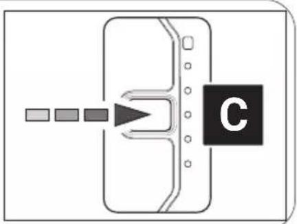
flowchart
graph TD
    A[" "] --> B[" "]
    B --> C[" "]
    C --> D["C"]
natural_image
Diagram of a device with a labeled component 'C' and directional arrow pointing to its screen (no text or symbols beyond the label)natural_image
Technical diagram of a mechanical component with pins and a downward arrow indicating a process (no text or symbols present)EJE PEDALIER
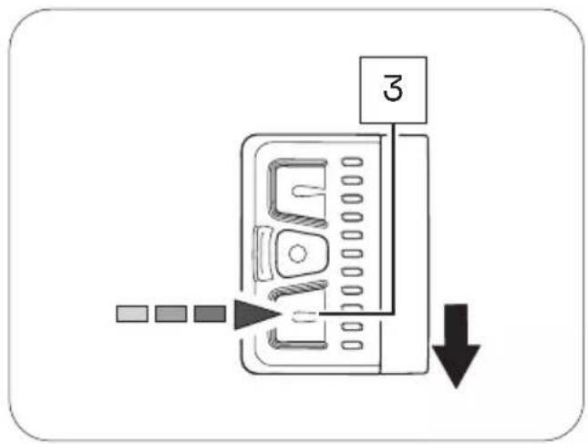
flowchart
graph TD
    A["Input 1"] --> B["Process Step"]
    B --> C["Output 2"]
Control remoto bXControl remoto fX
flowchart
graph TD
    A["Square Box"] --> B["Arrow pointing to Box"]
    B --> C["Box with Cross Shape"]
    C --> D["Label '1'"]
    style A fill:#f9f,stroke:#333
    style D fill:#bbf,stroke:#333
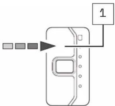
flowchart
graph TD
    A["Input 1"] --> B["Processing Step"]
    B --> C["Output 1"]
Control remoto bXControl remot
Addres and telephone number:
Trek US
Customer Service
801 W Madison street
Waterloo, Wisconsin 53594
USA
Telephone number: 920.478.4678
Internet: www.trekbikes.com
Limited warranty
Your bicycle is covered by a Lifetime Limited Warranty. Please visit our web site for details.
For Service and Warranty, please contact your local dealer.
Please refer to the Trek website (Menu/Support) for the latest revision of this manual.
New features, as described in the latest manual, may not be applicable on your electric bike.
Contacter
801 W Madison street
Waterloo, Wisconsin 53594
USA
Téléphone: 920.478.4678
Internet: www.trekbikes.com
Garantie limitée
801 W Madison street
Waterloo, Wisconsin 53594
USA