
VLS 064A RF AC - Fridge VESTFROST - Free user manual and instructions
Find the device manual for free VLS 064A RF AC VESTFROST in PDF.
User questions about VLS 064A RF AC VESTFROST
0 question about this device. Answer the ones you know or ask your own.
Ask a new question about this device
Download the instructions for your Fridge in PDF format for free! Find your manual VLS 064A RF AC - VESTFROST and take your electronic device back in hand. On this page are published all the documents necessary for the use of your device. VLS 064A RF AC by VESTFROST.
USER MANUAL VLS 064A RF AC VESTFROST
natural_image
Exterior view of a stainless steel laboratory refrigerator with temperature and humidity labels (no readable text beyond labels)
12
RESPONSIBLE CONSUMPTION AND PRODUCTION

Vestfrost Solutions is working towards reaching the UN - Global Sustainable Development Goals by 2030.
The Sustainable Development Goals are the blueprint to achieve a better and more sustainable future for all.
In order to implement Goal no 12 "Responsible Consumption and Production", this manual has been printed on recycled paper.


Model VLS 064A RF AC Internal Voltage Stabilizer
Combined Icelined Refrigerator/Waterpacks Freezer
GB Instructions for use
As the appliance contains a flammable refrigerant, R600a as stated on nameplate, it is essential to ensure that the refrigerant pipes are not damaged.
The quantity and type of the refrigerant used in your appliance is indicated on the rating plate.
Standard EN378 specifies that the room in which you install your appliance must have a volume of 1 m^3 per 8 g of hydrocarbon refrigerant used in the appliances. This is to avoid the formation of flammable gas/air mixtures in the room where the appliance is located in the event of a leak in the refrigerant circuit.
WARNING:
Ventilation openings in the appliance or in built-in structures must be kept clear.
WARNING:
Do not use other mechanical devices or means to accelerate the defrosting process or to remove rime other than those recommended by the manufacturer.
WARNING:
Do not damage the refrigerant system.
WARNING:
The appliance may not be exposed to rain.
WARNING:
This appliance is not intended for use by persons (including children) with reduced physical, sensory or mental capabilities, or lack experience and knowledge, unless they have been given supervision or instructions concerning use of the appliance by a person responsible for their safety. Children should be supervised to ensure that they do not play with the appliance
WARNING:
Children must not play with, on, or around the appliance.
WARNING:
Children must not clean the appliance or carry out general maintenance unless they are at least 8 years old and are being supervised.
WARNING:
Always, keep the keys in a separate place and out of reach of children.
WARNING:
Before servicing or cleaning the appliance, switch off circuit breaker.
text_image
Warning sign depicting a flame symbol in a triangle, indicating hazard or cautionWARNING:
Danger risk of fire or explosion. Flammable refrigerant R600a used, as stated on nameplate. To be repaired only by trained personnel.
WARNING:
Do not store explosive substances such as aerosol cans with a flammable propellant in this appliance.
WARNING:
When positioning the appliance, ensure the power cord is not trapped or damaged.
WARNING:
Do not locate multiple portable socket-outlets or portable power supplies at the rear of the appliance.
WARNING:
Appliance use flammable insulation blowing gas.
For information about safe disposal, please contact your local disposal service.
See section for Disposal.
Contents
WARNING 2
General information ....4
Get to know your VLS 064A RF AC....5
Electrical connection....6
Voltage stabilizers....6
HIGHLY IMPORTANT!......8
Placing the Fridge-tag ®....9
Installation ....10
Operation and function 11
Loading the appliance ....12
Freezing water packs 12
Maintenance and cleaning....13
Trouble shooting....14
Warranty, spare parts and service....15
Disposal....16
General information
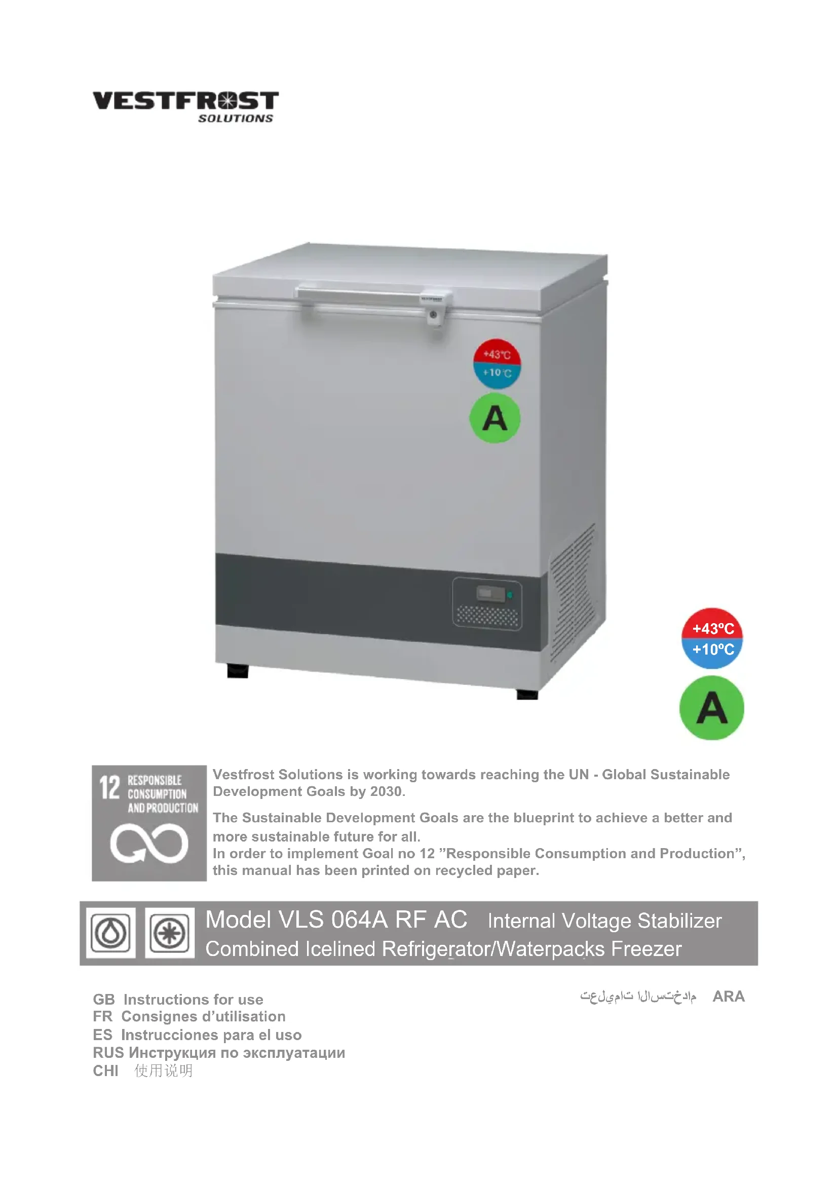
The VLS 064A RF AC is an ice-lined vaccine refrigerator (+2 to +8°C) equipped with basket. It has one compartment for storage of vaccine and one compartment for freezing and storage of water packs.
Technical data
See the rating plate, which is placed at the rear side of the appliance.
Unpacking and installation
- Unpack the appliance and check that it has not been damaged. If you observe any damage, inform your supervisor.
- Check the rating for correct voltage and frequency. (fig. 16 page 16)
- Open and remove all internal packing material.
Warning: For your own saftey, no person must attempt to lift this appliance without aid.
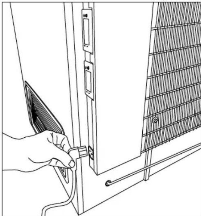
Plug in power cord here:
natural_image
Line drawing of a hand inserting a cable into a door panel with a grid-patterned panel on the right (no text or symbols)fig. 1
| PQS Code | Model PQS Performance specificationsSpecification reference: | PQS Independent type-testing protocolProduct verification protocol: |
| E003/070 VLS 064 RF AC E003 | /RF03.4 E003/RF03-VP.3 |
Get to know your VLS 064A RF AC

text_image
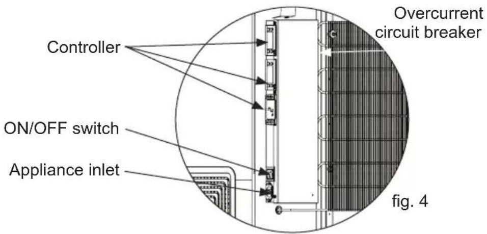
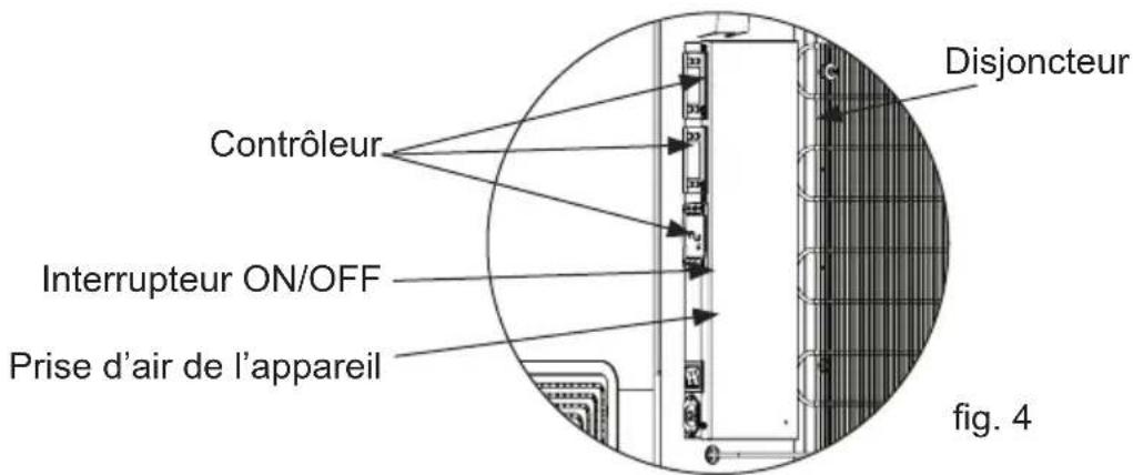
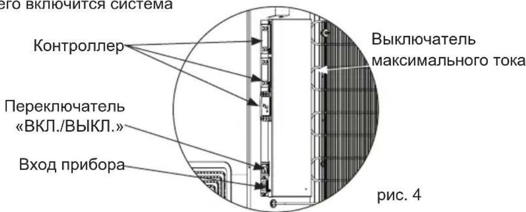
Basket Handle Lid Gasket Inner lid Bottom grate Vaccine storage Freezing Compartment Compressor compartment with ventilation grille Overcurrent circuit breaker Temperature display Controller ON/OFF switch Appliance inlet fig. 2Electrical connection
This device complies with relevant EU directives including Low Voltage Directive 2014/35/EU and Electromagnetic Compatibility Directive 2014/30/EU
The socket should be freely accessible.
Connect the appliance only to 220-240V 50/60Hz mains supply via a correctly installed earthed socket.
The socket must be fused with a 10-13 A fuse.
If the appliance is to be operated in a non-European country, check on the rating plate whether the indicated voltage and current correspond to the values of your mains supply.
Information regarding voltage, current or power are given on the rating plate
Check that the plug fits your type of socket. If it does not fit, procure an appliance cord with the correct plug or have a qualified electrician to fit the plug according to country standards. This appliance must be earthed.
Do not plug several appliances and the refrigerator into the same multiple power strip. The refrigerator should always be plugged into its own individual electrical outlet which has a voltage rating that matches the voltage listed on the refrigerator's rating plate. Ensure that the plug and socket matches and that the appliance is earthed.
Voltage stabilizers
In order to protect the electrical components, the appliance is equipped with an internal voltage stabilizer for extended input range, that will safeguard the equipment against high/low mains voltage, high/low spikes and surges protection in line with WHO/PQS E007/VS01-VP.5
The internal extended stabilizer monitors the mains voltage continuously. If the voltage rises or drops, the stabilizer will stabilize the output to ensure the voltage reaching the appliance remains constant at 230V (+/-2%), within the operating range of the unit. If the input voltage falls below 110V or rises above 285V, the stabilizer will disconnect the output, thereby protecting the load. Once the mains voltage returns within acceptable limits, the stabilizer will reconnect the output following a startup delay.
Delay in restoring supply:
When under or over-voltage cut-out has occurred and the input voltage has returned to the operating range, the output is automatically restored after the factory set delay time delay (3-3:30 minutes random) when the mains voltage again is within the recommended range and stable.
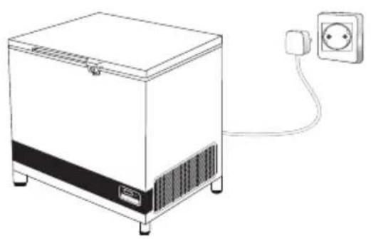
Standard operation instructions how to connect your appliance:
- Connect the appliance cable to the junction box
- Ensure that the switch on the appliance is turned OFF
- Plug the appliance plug into the wall mains socket
- Turn the power ON at the wall main socket
- Turn the switch on the appliance ON
- The internal stabilizer has a built-in AVS (Automatic Voltage Switcher). This will ensure that the load is not connected immediately. The delay will ensure that the mains is good before connecting the load and protects the equipment from rapid switching on and off.
- Once the waiting period (3-4 min.) has passed, the stabilizer will release power to the appliance, and the cooling system will turn on
natural_image
Line drawing of a portable appliance with a power outlet connected to its side panel (no text or symbols)
natural_image
Line drawing of a refrigerator with a power outlet connected to it (no text or symbols)fig. 3
text_image
Overcurrent circuit breaker Controller ON/OFF switch Appliance inlet fig. 4WARNING!
HIGHLY IMPORTANT!
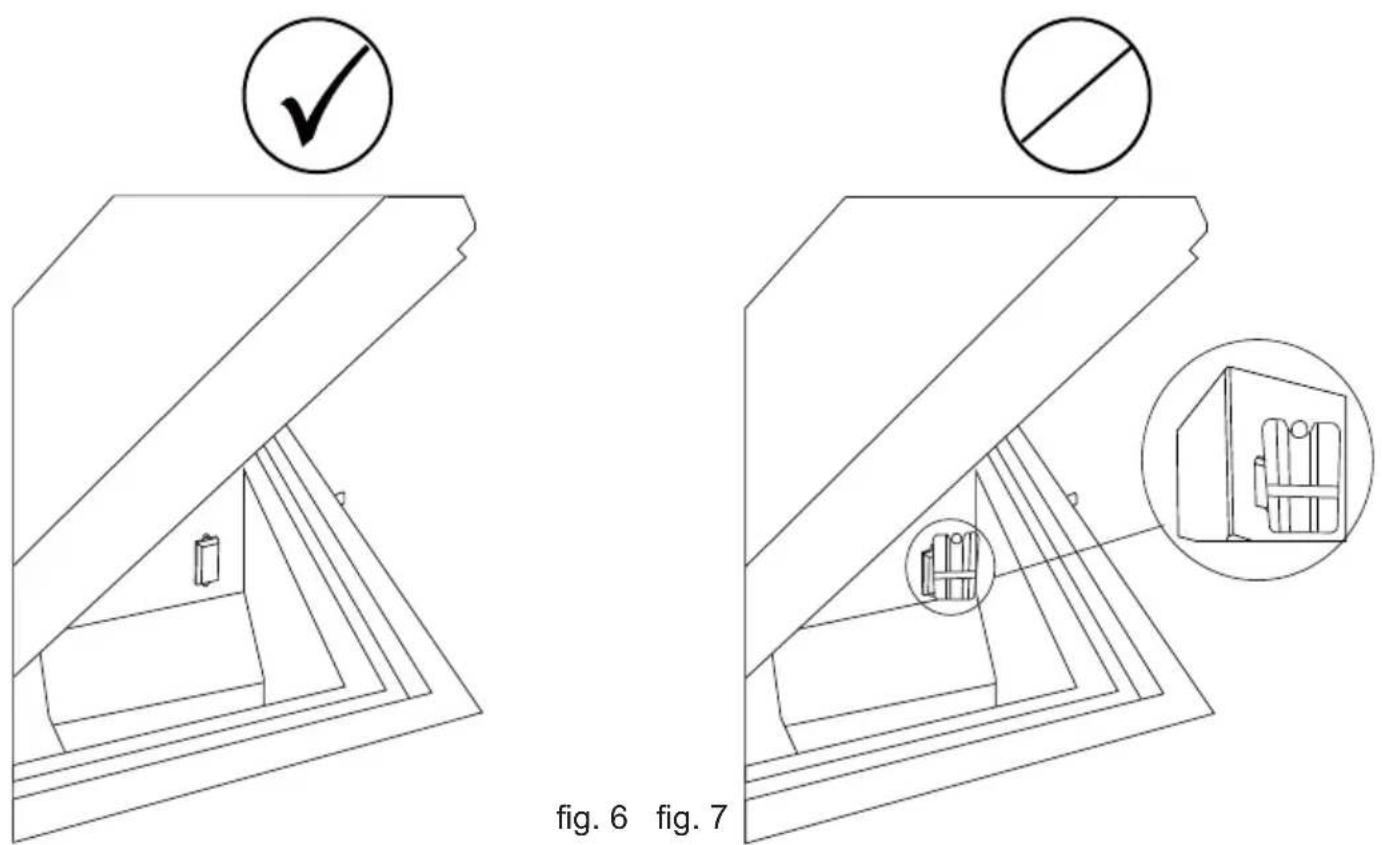
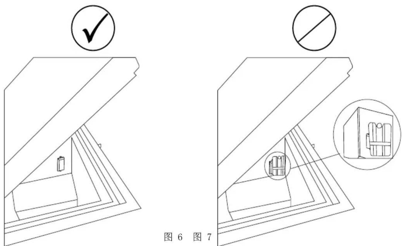
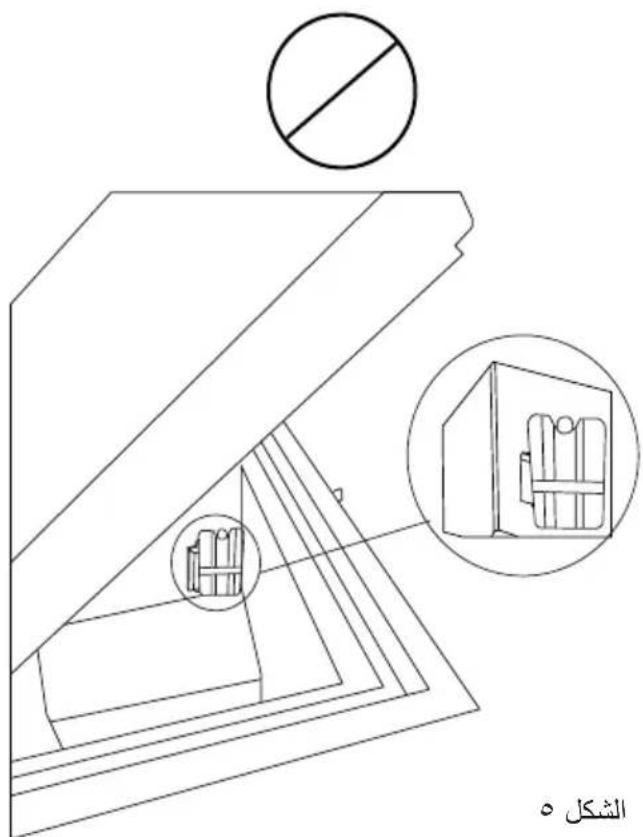
- Make sure NEVER to place any commodites up against the sensor cover.
Eg. Water-pack
natural_image
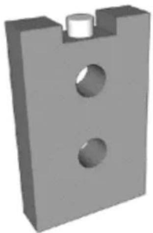
3D rendered mechanical part with two circular holes and a central cylindrical feature (no text or symbols)fig. 5
Placing the Fridge-tag ®
The activated Fridge-tag must be placed immediately in its predetermined location. It is recommended and important to place the device in the centre of the refrigerator for an optimal temperature observation.
External sensor
Two hours before activating the device the external sensor must be placed in its predetermined location. It is recommended and important to place the external sensor in the centre of the refrigerator for an optimal temperature observation and to avoid any incorrect measurements when starting the device
natural_image
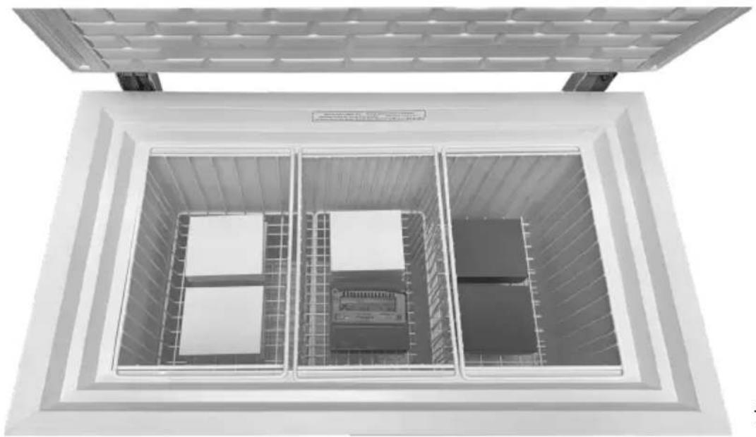
Top-down view of a large industrial storage or processing unit with internal compartments and control panels (no visible text or symbols)fig. 8
Fridge-tag
Support

text_image
QR code image containing encoded data, no visible human-readable textInstallation
Location
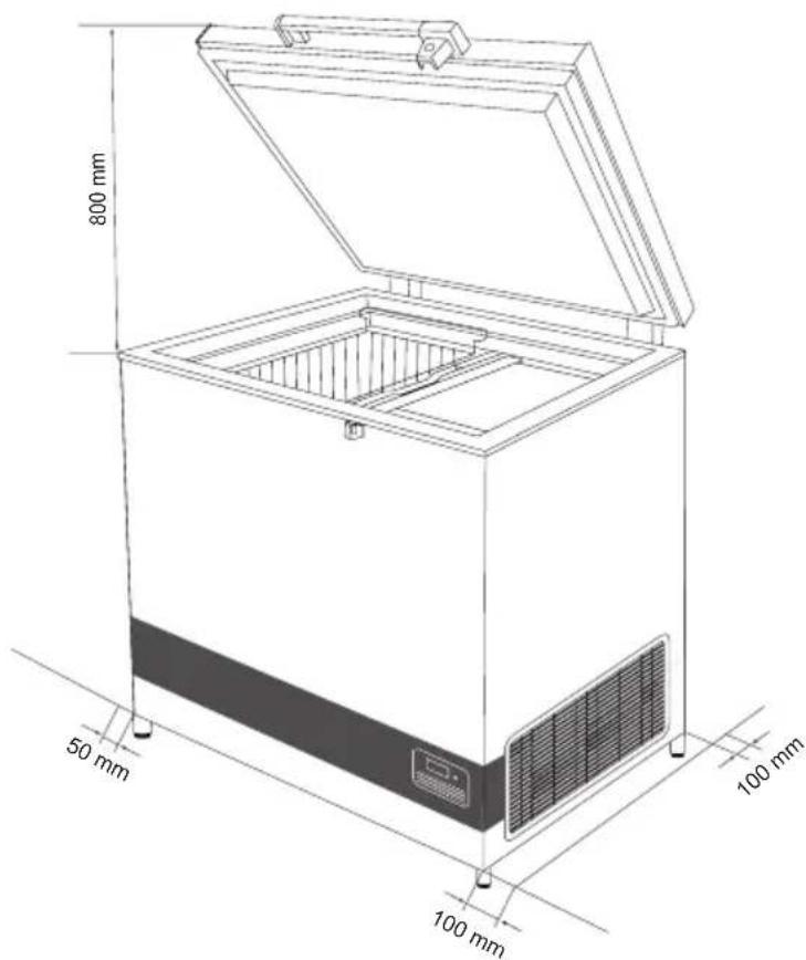
The appliance must be placed in a well ventilated room, not in direct sunlight and away from other heating sources.
When installing the appliance please ensure that the floor is level. Please see fig.8 for further directions.
text_image
800 mm 50 mm 100 mm 100 mmfig. 9
There must be at least 30 mm clearance between the base of the appliance and the floor.
IMPORTANT! There must be free access to the ventilation grille (fig. 10).

natural_image
Technical line drawing of a mechanical component with concentric grooves and mounting brackets (no text or symbols)fig. 10
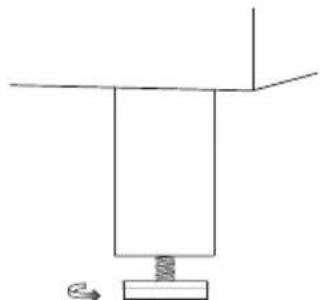
Adjustable feet
Level the appliance by screwing the adjustable feet up or down.
If the appliance is to be placed on a soft surface, e.g. floorboards or a carpet, it is best to recheck whether the appliance is still level after a period of time as the underlying surface may give under the weight of the appliance.
natural_image
Simple line drawing of a mechanical setup with a vertical component and a spring, no text or symbols present.fig. 11
Operation and function
text_image
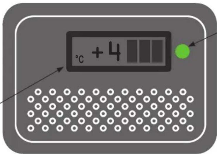
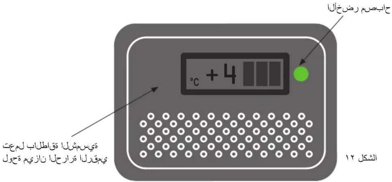
℃ + 4- Green diode
The green diode indicates that there is power.
- Solar-thermometer
fig. 12
Electronic thermostat
The appliance has an electronic thermostat that controls the temperature in the vaccine compartment. The thermostat is set by the factory.
- The green diode is on when the appliance is connected to the power supply, and the refrigeration system is operating.
- Solar Thermometer.
Starting procedure
Connect the mains lead to the power supply. The green diode must light (fig. 12) to indicate that the appliance is operating. The electronic thermostat makes a self test, 20 seconds before the compressor starts.
Temperature control
It is recommended to check the inside temperature with an accurate thermometer twice a day. The inside temperature must be checked regularly according to WHO's standards and specifications.
Cool down of the appliance
Before the appliance is loaded with vaccines the ice-lining must be frozen. To ensure that the ice-lining is frozen do the following:
- Place a thermometer in the top basket.
- Let the refrigerator run for at least 48 Hours before loading vaccine.
- Check the temperature in the vaccine compartment (must be between +2° and +8°C).
The temperature in the vaccine compartment must always be monitored on the thermometer and be within the range +2° to +8°C. Due to tolerance of the thermostat you should always control the temperature during cool down.
Loading the appliance
Loading vaccines
When the temperature in the vaccine compartment has stabilized, i.e. and the temperature is between +2°C and +8°C and the compressor stops and starts, vaccines can be loaded.
To ensure air-circulation and prevent too low vaccine temperature, direct contact to the inside walls must be avoided in the top section of the cooler.

text_image
Cold surface Avoid direct contactfig. 13
natural_image
Line drawing of a white oven with an open lid and internal compartments (no text or symbols)fig. 14
Freezing water packs
The VLS 064A RF AC has a freezing capacity of 3 x 0.6 liter water packs /24h. Storage capacity is 6x 0,6 liter water packs.
- Place the 3 water packs in the slot-nearest center of the unit
- Place the lid on top of the freezing compartment
- The water packs will be frozen after 24h
- Move the frozen water packs to the 2. slot for storage
The unit is ready to freeze the next batch of water packs

natural_image
Technical line drawing of a mechanical assembly with internal components and alignment arrows (no text or symbols)fig. 15
Maintenance and cleaning
Daily maintenance:
The temperature in the vaccine compartment must always be monitored on the thermometer every day. Please note that the vaccine in the appliance may not freeze.
Weekly maintenance:
During normal use, water can accumulate at the bottom of the appliance; remove with a cloth or through the drainage hole.
Wipe of water droplets on the inside wall at the same time.
Under certain ambient conditions, rime can form on the inside wall of the freezer compartment. Remove the rime without using sharp edged tools.
Check if lid gasket is sealing tight to the top frame when the lid is closed. A tight sealing lid reduces accumulation of water and formation of rime significantly.
Monthly maintenance:
Clean the grill on the right side of the refrigerator once each month.
Yearly maintenance:
Electric connections and components are to be checked and cleaned once a year or more if necessary.
Cleaning
Disconnect the power supply before cleaning. The best way to clean the appliance is by using luke warm water with a small amount of unscented detergent. Never use cleaning agents that scour. Use a soft cloth. Rinse with clean water and dry thoroughly. It is important to prevent water from running into the control panel.
The gasket around the lid must be cleaned regularly to prevent discolouration and prolong service life. Use clean water. After cleaning the sealing strip, check that it continues to provide a tight seal.
If the appliance is not being used for any period of time, switch off the appliance, disconnect the power supply, empty the appliance, clean the inside, and leave the lid open to allow air circulation and prevent smells.
Trouble shooting
| Fault Possible cause Remedy | ||
| Compressor is not running | Be patient, it is most likely that the compressor will start within a few minutes. | If this is not the case, check the following:- Check that power is connected.- Check the circuit breaker- If the above is OK, call technical supervisor. |
| Compressor is running, and the temperature is too high | The ventilation grille is blocked.The lid is not closed properly.The temperature in the room in which the appliance is installed is too high. | Ensure unhindered air circulation.Ensure that the lid is closed properly.Shield the appliance against direct sun light and ensure more ventilation to the room. |
| No temperature is displayed | The thermometer is broken.There is not enough light for the solar sensor. | Change the thermometer.Turn on the light. |
Warranty, spare parts and service
Warranty disclaimer
Faults and damage caused directly or indirectly by incorrect operation, misuse, insufficient maintenance, incorrect building, installation or mains connection. Fire, accident, lightening, voltage variation or other electrical interference, including defective fuses or faults in mains installations are not covered by the warranty.
Repairs performed by others than approved service centres and any other faults and damage that the manufacturer can substantiate are caused by reasons other than manufacturing or material faults are not covered by the warranty.
Please note that changes to the construction of the appliance or changes to the component equipment of the appliance will invalidate warranty and product liability, and the appliance cannot be used lawfully.
Spare parts
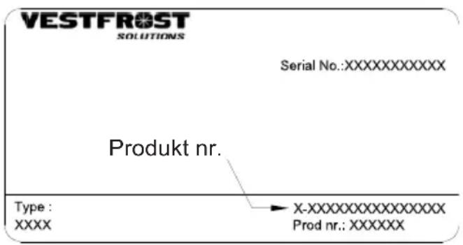
When ordering spare parts, please state the type, serial and product numbers of your appliance. This information is given on the rating plate (fig. 15). The rating plate contains various technical information, including type and serial numbers.
text_image
VESTFROST SOLUTIONS Serial No.:XXXXXXXXXX Produkt nr. Type: XXXX → X-XXXXXXXXXXXXXX Prod nr.: XXXXXXfig. 16
Disposal
Information for Users on Collection and Disposal of Old Equipment and used Batteries

These symbols on the products, packaging, and/or accompanying documents mean that used electrical and electronic products and batteries should not be mixed with general household waste. For proper treatment, recovery and recycling of old products and used batteries, please take them to applicable collection points, in accordance with your national legislation and the Directives 2012/19/EU and 2006/66/EC.
By disposing of these products and batteries correctly, you will help to save valuable resources and prevent any potential negative effects on human health and the environment which could otherwise arise from inappropriate waste handling.
For more information about collection and recycling of old products and batteries, please contact your local municipality, your waste disposal service or the point of sale where you purchased the items.
Penalties may be applicable for incorrect disposal of this waste, in accordance with national legislation.
For business users in the European Union.
If you wish to discard electrical and electronic equipment, please contact your dealer or supplier for further information.
Information on Disposal in other Countries outside the European Union
These symbols are only valid in the European Union. If you wish to discard this product, please contact your local authorities or dealer and ask for the correct method of disposal.
Note for the battery symbol :

This symbol might be used in combination with a chemical symbol. In this case it complies with the requirement set by the Directive for the chemical involved.
Avertissement
natural_image
Warning symbol of a flame inside a triangle (no text or numbers)AVERTISSEMENT:
natural_image
Line drawing of a hand inserting a cable into a door panel with a grid-patterned panel on the wall (no text or symbols)fig. 1
natural_image
Line drawings of two household appliances with power outlets and wiring, no text or symbols presentfig. 3
natural_image
3D rendered mechanical part with two circular holes and a central cylindrical feature (no text or symbols)fig. 5
natural_image
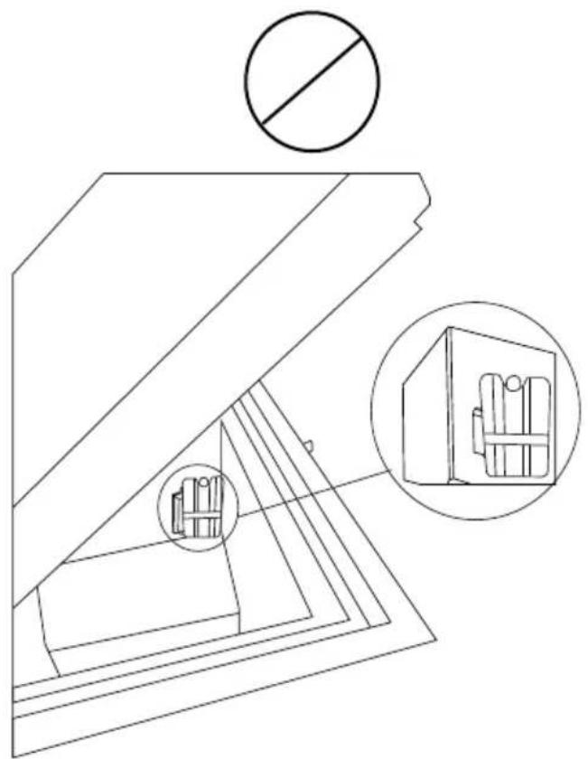
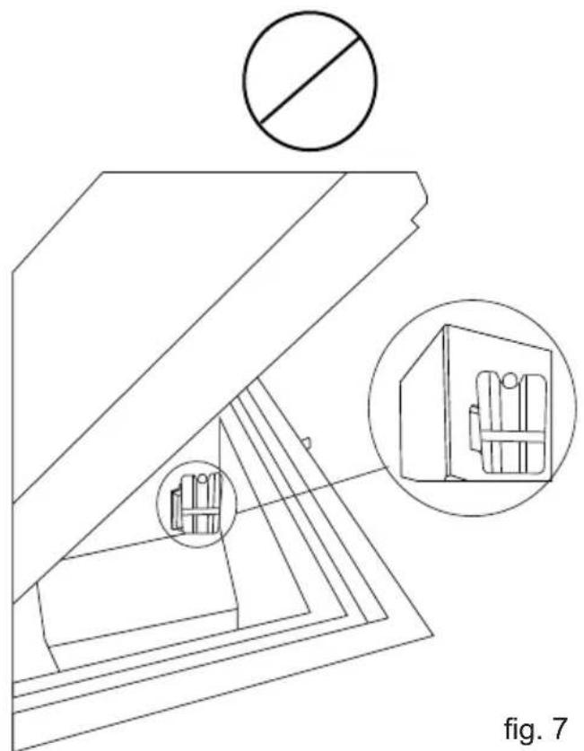
Line drawing of a staircase with a checkmark above it, no text or symbols presentfig. 6 fig. 7
natural_image
Technical line drawing of a mechanical assembly with cross-sections and a circular inset showing internal components (no text or symbols)natural_image
Top-down view of a large industrial storage unit with internal compartments and control panels (no visible text or symbols)fig. 8
Fridge-tag
Support

text_image
QR code image containing encoded data, no visible human-readable textInstallation
Emplacement
natural_image
Technical line drawing of a mechanical component with concentric circular features and mounting brackets (no text or symbols)fig. 10
Pieds
natural_image
Simple line drawing of a mechanical setup with a vertical beam and a spring, no text or symbols present.fig. 11
natural_image
Line drawing of a closed refrigerator with open lid and internal grating (no text or symbols)fig. 14
natural_image
Technical line drawing of a mechanical assembly with internal components and alignment lines (no text or symbols)fig. 15
natural_image
Warning symbol of a flame inside a triangle (no text or numbers)ADVERTENCIA:
natural_image
Line drawing of a hand inserting a cable into a door panel with a mesh grille (no text or symbols)fig.1
natural_image
Line drawing of a portable appliance with a power outlet connected to its side panel (no text or symbols)
natural_image
Line drawing of a portable appliance with a power outlet connected to it (no text or symbols)fig. 3

natural_image
3D rendered mechanical part with two circular holes and a central cylindrical feature (no text or symbols)fig. 5

natural_image
Line drawing of a cabinet interior with a checkmark above it (no text or symbols)fig. 6
natural_image
Technical line drawing of a mechanical assembly with cross-sections and detail views (no text or symbols)natural_image
Top-down view of a large industrial or storage chamber with internal compartments and grating (no visible text or symbols)fig. 8
Fridge-tag
Support

text_image
QR code image containing encoded data, no visible human-readable textInstalación
Ubicación
natural_image
Technical line drawing of a mechanical component with concentric grooves and mounting holes (no text or symbols)fig. 10
Pies ajustables
natural_image
Simple line drawing of a mechanical setup with a vertical beam and a spring, no text or symbols present.fig. 11
natural_image
Line drawing of a closed refrigerator with open lid and internal compartments (no text or symbols)fig. 14
natural_image
Technical line drawing of a mechanical assembly with internal components and alignment lines (no text or symbols)fig. 15
text_image
Warning sign depicting a flame symbol in a triangular shape, commonly used to indicate hazard or caution.natural_image
Line drawing of a hand inserting a cable into a door panel with a mesh grille (no text or symbols)рис. 1
natural_image
Line drawing of a portable air conditioner unit connected to an electrical outlet (no text or symbols)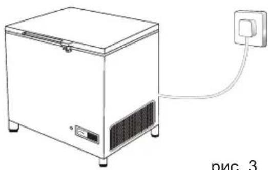
natural_image
Line drawing of a portable appliance with a power outlet connected to it (no text or symbols)рис. 3
natural_image
3D rendering of a gray mechanical part with two circular holes and a cylindrical top (no text or symbols)рис. 5

natural_image
Diagram of a mechanical assembly with a checkmark indicating selection (no text or symbols present)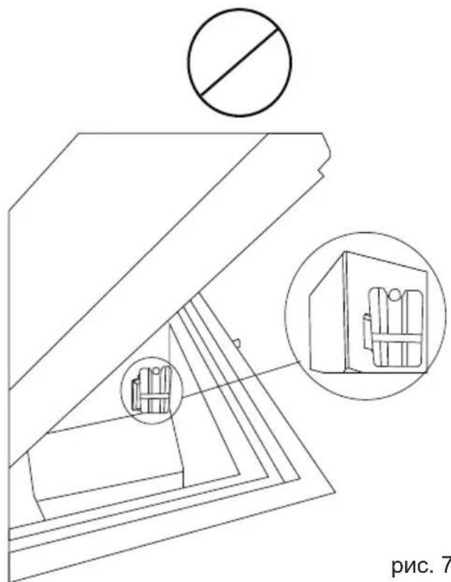
text_image
рис. 7рис. 7рис. 6
natural_image
Top-down view of a large industrial storage or processing unit with internal compartments and control panels (no visible text or symbols)рис.8
Fridge-tag Support

text_image
QR code image containing encoded data, no visible human-readable textУстановка
Выбор места
natural_image
Technical line drawing of a mechanical assembly with concentric rectangular components and mounting brackets (no text or symbols)Рис. 10
Регулируемые ножки
natural_image
Pure mechanical diagram showing a vertical component with a spring and a rectangular base, no text or symbols present.Рис. 11
natural_image
Line drawing of a closed refrigerator with open lid and internal compartments (no text or symbols)рис. 14
natural_image
Technical line drawing of a mechanical assembly with internal components and alignment lines (no text or symbols)рис. 15
text_image
Warning sign depicting a flame symbol in a triangular shape, indicating hazard or caution.natural_image
Line drawing of a hand inserting a cable into a door panel with a mesh grille (no text or symbols)图1
电气连接
natural_image
Line drawing of a portable air conditioner unit connected to an electrical outlet (no text or symbols)
natural_image
Line drawing of a portable appliance with a power outlet connected to its side panel (no text or symbols)图3

natural_image
3D rendering of a gray mechanical component with two circular holes and a cylindrical top (no text or symbols)图 5
放置温度显示器
natural_image
Top-down view of a large industrial storage or processing unit with three internal compartments and a top panel (no visible text or symbols)图8
Fridge-tag Support

text_image
QR code image containing encoded data, no visible human-readable text安装
位置
natural_image
Technical line drawing of a mechanical component with concentric grooves and mounting holes (no text or symbols)图 10
可调节脚
natural_image
Simple line drawing of a mechanical setup with a rectangular block and a base, no text or symbols present.图11
运行和功能

text_image
1。绿色灯 °C + 4 2。太阳能温度计图 12
电子温度调节器
natural_image
Line drawing of a closed storage cabinet with open lid and internal compartments (no text or symbols)图14
冷冻水包
natural_image
Technical line drawing of a mechanical assembly with internal components and directional arrows (no text or symbols)图15
保养和清洁
日常保养:
natural_image
Line drawing of a closed storage cabinet with open lid and internal compartments (no text or symbols)شکل 10
تحميل اللقاحات
natural_image
Technical line drawing of a mechanical assembly with internal components and directional arrows (no text or symbols)شکل ۱۶
التشغيل والوظيفة
natural_image
Technical line drawing of a mechanical component with no visible text or symbols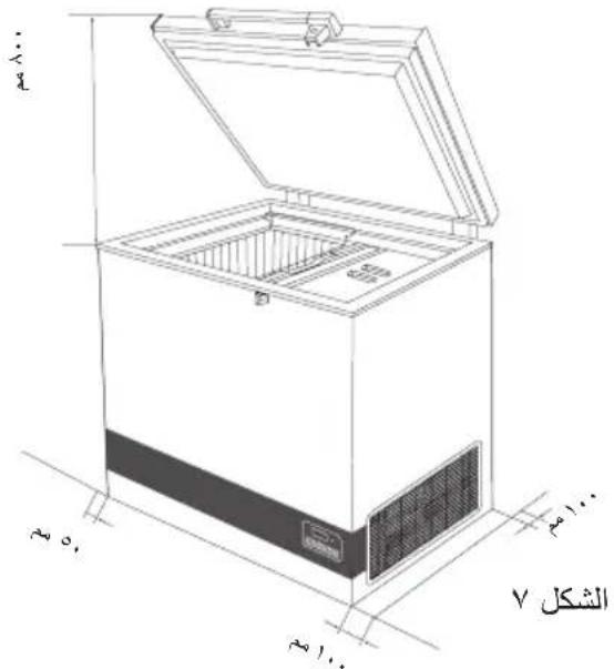
text_image
الشكل Vرجل قابلة للضبط
natural_image
Top-down view of a storage cabinet with three compartments and metal grilles (no visible text or symbols)الشكل ٦
Fridge-tag
Support

text_image
QR code image containing encoded data, no visible human-readable textمهم للغابة!
natural_image
3D rendering of a gray mechanical part with two circular holes and a cylindrical top (no text or symbols)الشكل ٣
natural_image
Line drawing of a cabinet interior with a battery inside, marked by a checkmark (no text or symbols)الشكل ٤
text_image
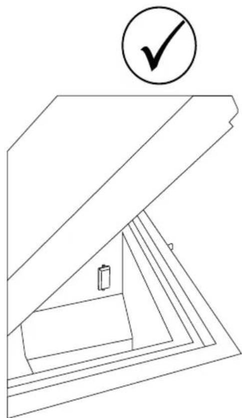
الشکل ۰الشكل ٥
VLS 064A RF AC
natural_image
Line drawing of a hand inserting a cable into a door panel with a grid-patterned panel on the wall (no text or symbols)معلومات عامة
text_image
Warning sign depicting a flame symbol in a triangular shape, indicating hazard or caution.
natural_image
Exterior view of a modern stainless steel laboratory refrigerator with temperature and humidity labels (no readable text beyond labels)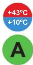

VLS 064SAOR4 AFC
مزح مایملا رزیرف / تجالث فطصا ؤعمت جم جل眺ا