
Syros 2.0 - Elliptical bike Horizon Fitness - Free user manual and instructions
Find the device manual for free Syros 2.0 Horizon Fitness in PDF.

User questions about Syros 2.0 Horizon Fitness
0 question about this device. Answer the ones you know or ask your own.
Ask a new question about this device
Download the instructions for your Elliptical bike in PDF format for free! Find your manual Syros 2.0 - Horizon Fitness and take your electronic device back in hand. On this page are published all the documents necessary for the use of your device. Syros 2.0 by Horizon Fitness.
USER MANUAL Syros 2.0 Horizon Fitness
Read the ELLIPTICAL GUIDE before using this OWNER'S MANUAL.
SAVE THESE INSTRUCTIONS
Read this ELLIPTICAL GUIDE before using the OWNER'S MANUAL. When using an electrical product, basic precautions should always be followed, including the following: Read all instructions before using this elliptical. It is the responsibility of the owner to ensure that all users of this elliptical are adequately informed of all warnings and precautions.


WARNING
TO REDUCE THE RISK OF BURNS, FIRE, ELECTRICAL SHOCK OR INJURY TO PERSONS:
- If you experience any kind of pain, including but not limited to chest pains, nausea, dizziness, or shortness of breath, stop exercising immediately and consult your physician before continuing.
- When exercising, always maintain a comfortable pace. Do not sprint above 80 RPMs on this machine. Incorrect or excessive exercise may damage your health.
• To maintain balance, it is recommended to keep a grip on the handlebars while exercising, mounting or dismounting the machine.
- Do not turn pedal arms by hand.
- Make sure handlebars are secure before each use.
- Keep the topside of the foot support clean and dry.
- Care should be taken when mounting or dismounting the equipment. Before mounting or dismounting, move the pedal on the mounting or dismounting side to its lowest position and bring the machine to a complete stop.
- Do not wear clothes that might catch on any part of the elliptical.
• Always wear athletic shoes while using this equipment.
- Do not jump on the elliptical.
- At no time should more than one person be on the elliptical while in operation.
- This elliptical is intended for in-home use only. Do not use this elliptical in any commercial, rental, school or institutional setting. Failure to comply will void the warranty.
- Do not use elliptical in any location that is not temperature controlled, such as but not limited to garages, porches, pool rooms, bathrooms, car ports or outdoors. Failure to comply will void the warranty.
• This elliptical complies with the EN957-1/9 standard, class of elliptical: HB; braking system is adjustable.
• To prevent electrical shock, never drop or insert any object into any opening.
Keep power cord away from heated surfaces. Do not carry this unit by it's supply cord or use the cord as a handle.
- Disconnect all power before servicing or moving the equipment. To clean, wipe surfaces down with soap and slightly damp cloth only; never use solvents. (See MAINTENANCE)
- Do not use other attachments that are not recommended by the manufacturer. Attachments may cause injury.
Do not operate where aerosol (spray) products are being used or when oxygen is being administered.
- Use the elliptical only as described in the elliptical guide and owner's manual.
- The equipment shall be installed on a stable base.

At NO time should children under the age of 13 be closer to the elliptical than 10 feet.
At NO time should children under the age of 13 use the elliptical.
Children over the age of 13 or disabled persons should not use the elliptical without adult supervision.
It is essential that your elliptical is used only indoors, in a climate controlled room. If your elliptical has been exposed to colder temperatures or high moisture climates, it is strongly recommended that the elliptical is warmed up to room temperature before first time use. Failure to do so may cause premature electronic failure.

GROUNDING INSTRUCTIONS
If an elliptical should malfunction or breakdown, grounding provides a path of least resistance for electrical current to reduce the risk of electrical shock. This product is equipped with a cord having an equipment-grounding conductor and a grounding plug. The plug must be plugged into an appropriate outlet that is properly installed and grounded in accordance with local codes and ordinances.
Improper connection of the equipment-grounding conductor can result in a risk of electric shock. Check with a qualified electrician or serviceman if you are in doubt as to whether the product is properly grounded. Do not modify the plug provided with the product. If it will not fit the outlet, have a proper outlet installed by a qualified electrician.

WARNING
Connect this exercise product to a properly grounded outlet only.
Never operate product with a damaged cord or plug even if it is working properly. Never operate any product if it appears damaged, or has been immersed in water. Contact your Locad Dealer for replacement or repair.
BASIC OPERATION
CONGRATULATIONS ON CHOOSING YOUR ELLIPTICAL!
You've taken an important step in developing and sustaining an exercise program! Your elliptical is a tremendously effective tool for achieving your personal fitness goals. Regular use of your elliptical can improve the quality of your life in so many ways.
Here are just a few of the health benefits of exercise:
- Weight loss
• A healthier heart - Improved muscle tone
• Increased daily energy levels
The key to reaping these benefits is to develop an exercise habit. Your new elliptical will help you eliminate obstacles that prevent you from exercising. Inclement weather and darkness won't interfere with your workout when you use your elliptical in the comfort of your home. This guide provides you with basic information for using and enjoying your new machine.


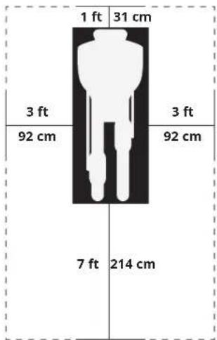
LOCATION OF THE ELLIPTICAL
Place the elliptical on a level surface. We advice there should be clearance around your elliptical trainer (see guide). Do not place the elliptical in any area that will block any vent or air openings.
POWER
Your elliptical is powered by a power supply. The power must be plugged into the power jack, which is located in the front of the machine near the stabilizer tube. Some ellipticals have a power switch, located next to the power jack. Make sure it is in the ON position. NOTE: Some ellipticals have an ON/OFF switch located behind the console.

WARNING
Never operate product if it has a damaged cord or plug, if it is not working properly, if it has been damaged, or immersed in water. Please contact our service centre for technical support, repair or new parts.
text_image
1 ft 31 cm 3 ft 3 ft 92 cm 92 cm 7 ft 214 cmFOOT POSITIONING
Your elliptical offers a variety of foot positions. Moving your foot to the forward most position of the foot pad increases your step height, which will create a feel similar to a step machine. Placing your foot toward the back of the foot pad decreases your step height and creates more of a gliding feel, similar to a smooth walk or run. Always make sure your entire foot is secured on the foot pad.
Your elliptical also allows you to pedal both forward and backwards to offer a variation to your workout and to focus on other major leg muscle groups such as your hamstrings and calves.
WORKOUT OPTIONS

FULL BODY WORKOUT
For a full body workout, push and pull continuously on the dual action arms while pedaling.
MOUNTING THE ELLIPTICAL
- Stand on the side of the elliptical next to the lowest foot pedal.
- While holding both of the stationary handlebars, place your foot on the lowest foot pedal and pull yourself up onto the elliptical.
- Wait until the elliptical finds its resting place and then place your other foot on the opposite pedal.

natural_image
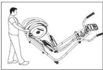
Line drawing of a person using a robotic device to interact with a mechanical device (no text or symbols present)MOVING THE ELLIPTICAL
Your elliptical has a pair of transport wheels built into the front stabilizer tube. To move, first remove the power supply and firmly grasp the steel portion of the rear stabilizer bar, carefully tilt and roll. NOTE: be sure to grab the steel bar and not the plastic cover.

WARNING
Our ellipticals are heavy, use care and additional help if necessary when moving. Failure to follow these instructions could result in injury.
LEVELING THE ELLIPTICAL
Your elliptical should be leveled for optimum use. Once you have placed your elliptical where you intend to use it, raise or lower one or both of the adjustable levelers located on the bottom of the elliptical frame*. A carpenter's level is recommended. Once you have leveled your elliptical, lock the levelers in place by tightening the nuts against the frame. *NOTE: Some ellipticals do not have levelers.
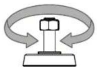
ADJUST HEIGHT

USING THE HEART RATE FUNCTION
Your elliptical could be equipped with either heart rate pulse grips or a thumb pulse sensor. To find out what your model has, refer to the beginning of the ASSEMBLY section of your OWNER'S MANUAL.
The heart rate function on this product is not a medical device. While heart rate grips or a thumb pulse sensor can provide a relative estimation of your actual heart rate, they should not be relied on when accurate readings are necessary. Some people, including those in a cardiac rehab program, may benefit from using an alternate heart rate monitoring system like a chest or wrist strap. Various factors, including movement of the user, may affect the accuracy of your heart rate reading. The heart rate reading is intended only as an exercise aid in determining heart rate trends in general. Please consult your physician.
PULSE GRIPS
Place the palm of your hands directly on the grip pulse handlebars. Both hands must grip the bars for your heart rate to register. It takes 5 consecutive heart beats (15-20 seconds) for your heart rate to register. When gripping the pulse handlebars, do not grip tightly. Holding the grips tightly may elevate your blood pressure. Keep a loose, cupping hold. You may experience an erratic readout if consistently holding the grip pulse handlebars. Make sure to clean the pulse sensors to ensure proper contact can be maintained.

CAUTION
Do not press excessively hard on the sensor as this may cause damage.
ASSEMBLY

WARNING
There are several areas during the assembly process that special attention must be paid. It is very important to follow the assembly instructions correctly and to make sure all parts are firmly tightened. If the assembly instructions are not followed correctly, the elliptical could have frame parts that are not tightened and will seem loose and may cause irritating noises. To prevent damage to the elliptical, the assembly instructions must be reviewed and corrective actions should be taken.
Before proceeding, find your elliptical's serial number located on the front stabilizer tube and enter it in the space provided below. Also locate the model name which is next to the serial number.
ENTER YOUR SERIAL NUMBER AND MODEL NAME IN THE BOXES BELOW:
SERIAL NUMBER:

MODEL NAME:

text_image
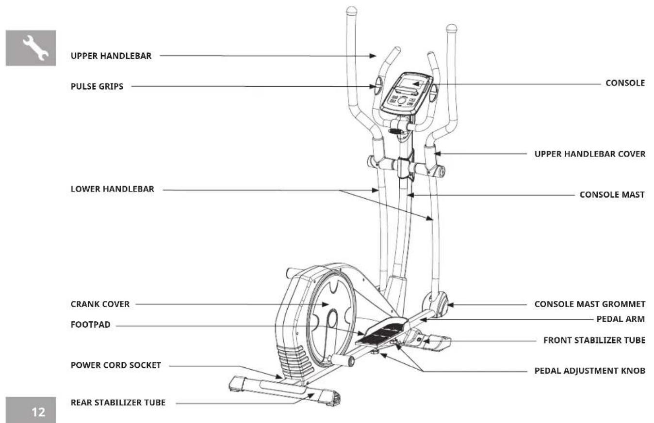
UPPER HANDLEBAR PULSE GRIPS CONSOLE UPPER HANDLEBAR COVER LOWER HANDLEBAR CONSOLE MAST CRANK COVER FOOTPAD CONSOLE MAST GROMMET PEDAL ARM FRONT STABILIZER TUBE POWER CORD SOCKET PEDAL ADJUSTMENT KNOB REAR STABILIZER TUBE 12TOOLS INCLUDED:
□ 5mm L Wrench
□ Flat Wrench
PARTS PACKING INCLUDED:
□ 1 Main Frame
□ 1 Front Stabilizer Tube
□ 1 Rear Stabilizer Tube
□ 1 Console
□ 1 Console Mast
□ 1 Console Mast Grommet
□ 2 Upper Handlebars
□ 2 Lower Handlebars
□ 2 Upper Handlebar Covers
□ 2 Pedals
□ 2 Pedal Arms
□ 1 Power Cord
□ 1 Hardware Kit
PRE ASSEMBLY
UNPACKING
Unpack the product where you will be using it. Place the elliptical carton on a level flat surface. It is recommended that you place a protective covering on your floor. Never open box when it is on its side.
WARNING
- It is recommended that two people work together for ease and efficiency while assembling an elliptical.
- During each assembly step, ensure that ALL nuts and bolts are in place and partially threaded. It is recommended you complete the full assembly of your unit before completely tightening any ONE bolt.
- Several parts have been pre-lubricated to aid in assembly and usage. Please do not wipe this off. If you have difficulty, a light application of lithium bike grease is recommended.
NEED HELP?
If you have questions or if there are any missing parts, contact Customer Tech Support.


ASSEMBLY STEP 1
text_image
Technical diagram of a mechanical exercise machine with numbered components and labeled partsHARDWARE PARTS:

BOLT (14)
M8×20
QTY: 4

SPRING WASHER (101)
Φ8
QTY: 4

FLAT WASHER (102)
Φ8×Φ20×2.5T
QTY: 4
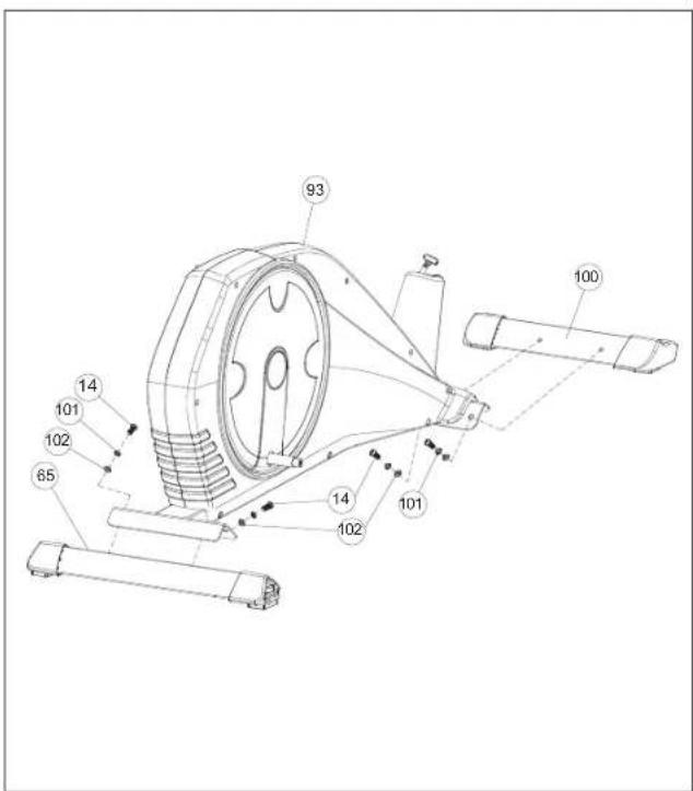
A Attach the REAR STABILIZER TUBE (65) to MAIN FRAME (93) using 2 BOLTS (14) & WASHERS (101 & 102).
B Attach the FRONT STABILIZER TUBE (100) to MAIN FRAME (93) using 2 BOLTS (14) & WASHERS (101 & 102).
ASSEMBLY STEP 2

text_image
Technical diagram of a mechanical device with numbered parts and exploded views, likely for assembly or maintenance instructions.NOTE: There is no hardware for this step.
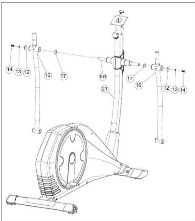
A Slide CONSOLE MAST GROMMET (98) from bottom up the CONSOLE MAST (21).
B Attach CONSOLE CABLES (2 & 97) and tuck cables into MAIN FRAME (93) carefully.
C Slide CONSOLE MAST (21) into MAIN FRAME (93) using 4 PRE-INSTALLED BOLTS (96), 4 PRE-INSTALLED ARC WASHER (13), 4 PREINSTALLED FLAT WASHERS (94) from left & right sides and 4 PRE-INSTALLED BOLTS (96), 4 PRE-INSTALLED ARC WASHER (13), 4 PREINSTALLED ARC WASHERS (95) from front & rear sides.
NOTE: Be careful not to pinch any wires while attaching the console mast.


ASSEMBLY STEP 3
text_image
Technical diagram of a stationary exercise machine with numbered components for identification.NOTE: There is no hardware for this step.
A Slide AXLE (103) through CONSOLE MAST (21) carefully.
B Attach the LOWER HANDLEBAR (16) to CONSOLE MAST (21) using 1 PRE-INSTALLED BOLT (14), 1 PREINSTALLED FLAT WASHER (12), 1 PRE-INSTALLED ARC WASHER (13) & 1 PRE-INSTALLED WAVED WASHER (17).
C Repeat steps B on the opposite side.
ASSEMBLY STEP 4
text_image
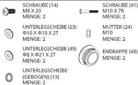
Technical diagram of a stationary exercise machine with numbered components and labeled partsHARDWARE PARTS:
text_image
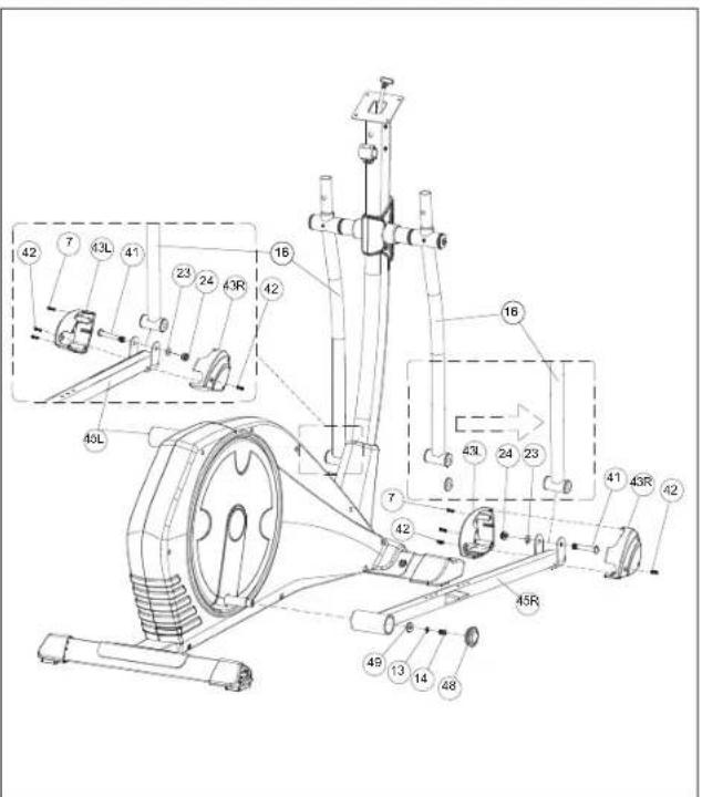
BOLT (14) M8 X 20 QTY: 2 FLAT WASHER (23) Φ10 X Φ19 X 2T QTY: 2 FLAT WASHER (49) Φ8 X Φ21 X 2T QTY: 2 ARC WASHER (13) Φ8 QTY: 2 BOLT (41) M10 X 78 QTY: 2 NUT (24) M10 QTY: 2 END CAP (48) QTY: 2A Slide PEDAL ARM (45R) to CRANK using 1 FLAT WASHER (49), 1 ARC WASHER (13), 1 BOLT (14) & 1 END CAP (48).
B Align opposite end of PEDAL ARM (45R) on the bottom of LOWER HANDLEBAR (16), secure the joint with 1 BOLT (41), 1 FLAT WASHER (23) and 1 NUT (24).
C Attach the PEDAL ARM COVER (43R & 43L) from both side of PEDAL ARM (45R) using 2 PRE-INSTALLED BOLTS (42) and 2 PRE-INSTALLED SCREWS (7).
D Repeat steps A-C on the opposite side.


ASSEMBLY STEP 5
text_image
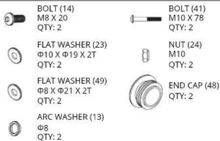
Technical diagram of an exercise machine with labeled components and parts, including numbered parts and exploded view.HARDWARE PARTS:
BOLT (46) M8 X 50

PEDAL KNOB (54) M8 QTY: 4

SPRING WASHER (53) Φ8 QTY: 4

FLAT WASHER (52) Φ8.5 X Φ16 X 2T QTY: 4
A Attach the PEDAL (47R) to PEDAL ARM (45R) using 2 BOLTS (46), 2 FLAT WASHERS (52), 2 SPRING WASHERS (53) and 2 PEDAL KNOBS (54).
B Repeat on the opposite side.
ASSEMBLY STEP 6
text_image
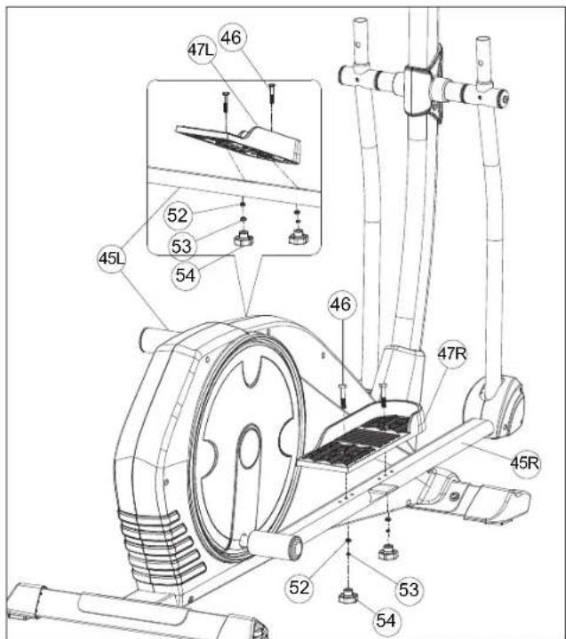
6L 6R 96 13 95 16 96 13 95 16HARDWARE PARTS:

BOLT (96)
M8 X 20
QTY: 4

ARC WASHER (95)
Φ8 X Φ19 X 1.5T
QTY: 4

SPRING WASHER (13)
中8
QTY: 4
A Slide UPPER HANDLEBAR (6R) onto LOWER HANDLEBAR (16) and secure using 2 BOLT (96), 2 ARC WASHER (95) and 2 SPRING WASHER (13).
B Repeat A on the other side.


ASSEMBLY STEP 7
text_image
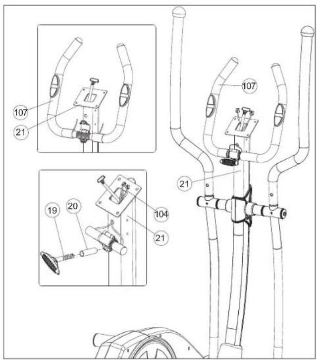
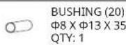
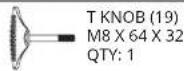
Technical diagram of a mechanical device with numbered parts and exploded views, likely for assembly or maintenance instructions.HARDWARE PARTS:
A Feed the HANDLBAR WIRES (104) through the hole in the CONSOLE MAST (21) and out the top of the CONSOLE MAST (21).
B Attach the HANDLEBAR (107) to CONSOLE MAST (21) using 1 BUSHING (20) and 1 T KNOB (19).
ASSEMBLY STEP 8
text_image
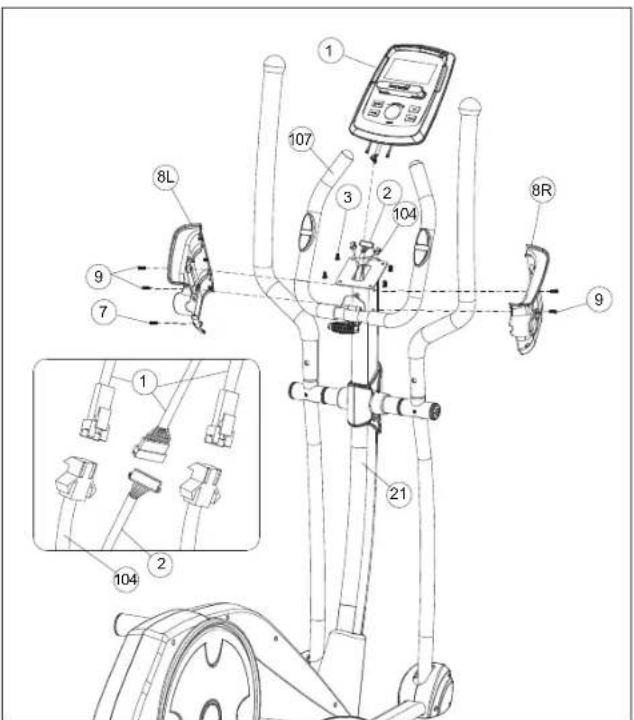
Technical diagram of a stationary exercise machine with labeled components and wiring detailsHARDWARE PARTS:

BOLT (7)
M4×15
QTY: 1
A Connect the CONSOLE CABLES (1 & 2 & 104) and carefully tuck the CONSOLE CABLES (1 & 2 & 104) into the CONSOLE MAST (21).
B Attach the CONSOLE (1) to the CONSOLE MAST (21) using 4 PRE-INSTALLED BOLTS (3).
C Attach the LEFT & RIGHT CONSOLE MAST COVERS (8R & 8L) to the CONSOLE MAST (21) using 4 PRE-INSTALLED BOLTS (9) and 1 BOLT (7).
NOTE: Be careful not to pinch any wires while attaching the console.


ASSEMBLY STEP 9
text_image
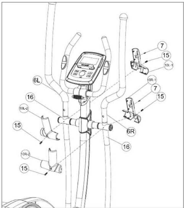
Technical diagram of a stationary bike with labeled components and partsHARDWARE PARTS:

BOLT (7) M4 X 15 QTY: 2

BOLT (15) M5 X 12 QTY: 4
A Attach the HANDLEBAR COVERS (10R-1 & 10R-2) from front side using 1 PRE-INSTALLED BOLT (15) and 1 BOLT (7) and rear side using 1 PREINSTALLED BOLT (15).
B Repeat A on the other side.
C Plug in POWER ADAPTER.
ASSEMBLY STEP 10
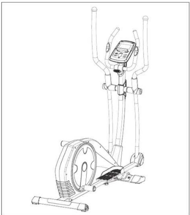
natural_image
Line drawing of a stationary exercise machine with dual arms and control panel (no text or symbols)ASSEMBLY COMPLETE!
SYROS 2.0
Max. User Weight: 150 kg / 330 lbs.
Overall Dimensions: 153 x 63 x 163 cm / 60.2" x 24.8" x 64.2"
This section explains how to use your elliptical's console and programming. For the BASIC OPERATION please see the ELLIPTICAL GUIDE

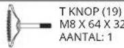
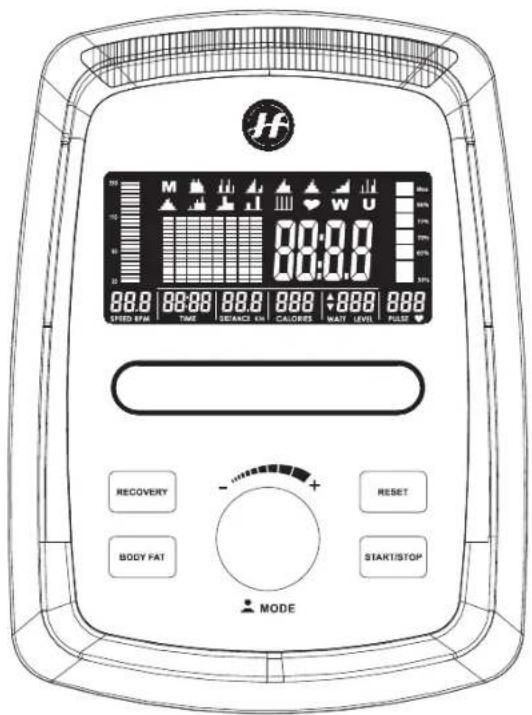
SYROS 2.0 CONSOLE DISPLAY


text_image
M W U 00:00 00:00 88.8 88.88 88.8 88.8 88.8 88.8 STRED RPM TIME INSURANCE FAI CALORIES NAST LEVEL FUSH RECOVERY BODY FAT RESET START/STOP MODESYROS 2.0 CONSOLE OPERATION
A) INTELLIGENT WHEEL
Turn to select programs, set up resistance level and workout numbers. Press to confirm.
B) RESET KEY
Press and hold for 2 seconds to reboot the console.
C) START/STOP KEY
Start or stop workout.
D) RECOVERY KEY
Test heart rate recovery status.
E) BODY FAT KEY
Test body fat % and BMI.
F) RACK
Hold your phone or tablet.
G) LCD DISPLAY
Speed, RPM, time, distance, calories, watt, heart rate.


SYROS 2.0 CONSOLE OPERATION
SETUP YOUR PERSONAL DATA
Turn the intelligent drive to select U1\~U4, the set SEX, AGE, HEIGHT, WEIGHT and press this drive to confirm.
START YOUR WORKOUT
Turn the intelligent drive to select workout.

text_image
M W UM MANUAL
Use intelligent drive to select program at main menu and press to confirm. Press START/STOP key to star workout.
PRESET PROGRAM

natural_image
Collection of black silhouette icons representing industrial structures or facilities (no text or symbols)There are 12 preset programs, use intelligent drive to select at main menu and press to confirm. Press START/STOP key to star workout.

HRC
Use intelligent drive to select program at main menu and press to enter. Select 55%, 75%, 90% or TAG (target heart rate, 100%) Press START/STOP key to star workout.

WATT
Use intelligent drive to select program at main menu and press to enter. Set up WATT target and Time. Press START/STOP key to star workout.

USER PROGRAM
Use intelligent drive to select program at main menu and press to enter. Create customized resistance workout and training time. Press START/STOP key to star workout.
RECOVERY
After exercising for a period, keep holding on hand grips or wearing heart rate strap and press RECOVERY button. All function display stop except time which count down from 60 to 0 second. Then display shows up heart rate recovery status from F1, F2....to F6. F1 is the best recovery status.
BODY FAT
In STOP mode, press BODY FAT button to start the measurement. Console shows U1 or U2 or U3 or U4 base on different user profile and start measuring. LCD displays BMI, FAT % and BODY FAT advice symbol after measuring.
*It is necessary to hold both hands on the hand grip during data measurement
*It takes 8 seconds to get the results
ENERGY SAVE
Without pedaling or there is no heart rate been received, 4 minutes later the console is entering energy save model. Press any key to wake up the console.
APP
This model is APP compatible, users can download "i-Console +" or "Fit Hit Way" from Google Play or App Store


MONITORING YOUR HEART RATE
FEEDBACK
Your Horizon Fitness elliptical trainer offers two heart rate feedback options. You may choose to use the heart rate handlebars, or the chest transmitter (sold separately) for a hands free workout.
HEART RATE HANDLEBAR
Place the palm of your hands directly on the heart rate handlebars. Both hands must grip the bars for your heart rate to register. When gripping the handlebars, do not grip tightly. Holding the grips tightly may elevate your blood pressure. Try to maintain moderate pressure while holding onto the heart rate handlebars. It is recommended that you hold the handlebars only long enough the see your heart rate readout on the console. You may experience an erratic readout if consistently holding the handlebars.
TELEMETRIC CHEST TRANSMITTER (SOLD SEPARATELY)
Prior to wearing the chest transmitter on your chest, moisten the two rubber electrodes with water. Center the chest strap just below the breast or pectoral muscles, directly over your sternum, with the logo facing out. NOTE: The chest strap must be tight and properly placed to receive an accurate and consistent readout. If the chest strap is too loose, or positioned improperly, you may receive an erratic or inconsistent heart rate readout.
If you have any problems with the heart rate function please refer to pages 10, 11 and 24 in the elliptical guide.
WARNING!
The heart rate function is not a medical device. Various factors may affect the accuracy of your heart rate reading. The heart rate reading is intended only as an exercise aid.
SYROS 2.0 EXPLODED VIEW
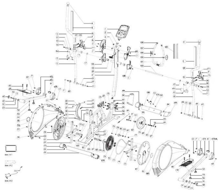
text_image
Exploded view diagram of a mechanical device with numbered components and labeled parts, including zoomed-in parts and component labels.SYROS 2.0 PARTS LIST
| NO. | DESCRIPTION | QTY |
| 1 COMPUTER 1 | ||
| 2 UPPER COMPUTER CABLE 1 | ||
| 3 SCREW M5X10MM 4 | ||
| 4 END CAP 2 | ||
| 5 UPPER HANDLEBAR FOAM 2 | ||
| 6L UPPER HANDLEBAR LEFT 1 | ||
| 6R UPPER HANDLEBAR RIGHT 1 | ||
| 7 SELF-TAPING SCREW 7 | ||
| 8L COMPUTER PLASTIC COVER LEFT 1 | ||
| 8R COMPUTER PLASTIC COVER RIGHT 1 | ||
| 9 SCREW M5X12MM 7 | ||
| 10L-1 LEFT PLASTIC COVER FRONT | 1 | |
| 10L-2 LEFT PLASTIC COVER BACK | 1 | |
| 10R-1 | RIGHT PLASTIC COVER FRONT | 1 |
| 10R-2 | RIGHT PLASTIC COVER BACK | 1 |
| 11 BUSHING | 6 | |
| 12 FLAT WASHER | 2 | |
| 13 CURVED WASHER | 16 | |
| 14 ALLEN BOLT | 8 | |
| 15 SCREW | 4 | |
| 16 LOWER CONNECTION TUBE | 2 | |
| 17 CURVED WASHER | 2 | |
| 18L | PLASTIC COVER FRONT | 1 |
| 18R | PLASTIC COVER BACK | 1 |
| 19 T SHAPE KNOB | 1 | |
| NO. | DESCRIPTION | QTY |
| 20 TUBE | 1 | |
| 21 CONSOLE MAST | 1 | |
| 22 TUBE | 2 | |
| 23 FLAT WASHER | 2 | |
| 24 NUT M10 | 3 | |
| 25 SCREW M5X15MM 3 | ||
| 26 MOTOR | 1 | |
| 27 NUT M6 | 2 | |
| 28 STUD | 1 | |
| 29 CONE SPRING | 1 | |
| 30 IDLER SET AXLE | 1 | |
| 31 FLAT WASHER | 2 | |
| 32 FLAT WASHER | 2 | |
| 33 C SHAPE WASHER | 1 | |
| 34 HEXAGON BOLT | 2 | |
| 35 SPRING WASHER | 2 | |
| 36 MAGNET SET | 1 | |
| 37 PLASTIC WASHER | 1 | |
| 38 FLAT WASHER | 1 | |
| 39 HEX NUT | 1 | |
| 40 BUSHING | 4 | |
| 41 ALLEN BOLT | 2 | |
| 42 SCREW | 4 | |
| 43L | FOOTPLATE COVER LEFT | 2 |
| 43R | FOOTPLATE COVER RIGHT | 2 |
| 44 END CAP 2 | ||
| 45L PEDAL BAR LEFT 1 | ||
| 45R PEDAL BAR RIGHT 1 | ||
| 46 ALLEN BOLT 4 | ||
| 47L FOOTPLATE LEFT 1 | ||
| 47R FOOTPLATE RIGHT 1 | ||
| 48 END CAP 2 | ||
| 49 FLAT WASHER 2 | ||
| 50 C SHAPE WASHER 2 | ||
| 51 BEARING 2 | ||
| 52 FLAT WASHER 4 | ||
| 53 SPRING WASHER | 4 | |
| 54 HEX KNOB | 4 | |
| 55 DECORATION FOR ROUND COVER | 2 | |
| 56L CHAIN COVER LEFT | 1 | |
| 56R CHAIN COVER RIGHT | 1 | |
| 57 SELF-TAPING SCREW | 6 | |
| 58 SCREW | 6 | |
| 59 FLANGE NUT | 2 | |
| 60 CONNECTING TUBE | 2 | |
| 61 ROUND COVER | 2 | |
| 62 CRANK | 2 | |
| 63L REAR END CAP LEFT | 1 | |
| 63R REAR END CAP RIGHT | 1 | |
| 64 SELF-TAPING SCREW | 8 |
| NO. | DESCRIPTION | QTY |
| 65 REAR STABILIZER BAR | 1 | |
| 66 DC CABLE | 1 | |
| 67 | BEARING | 2 |
| 68 FLAT WASHER 2 | ||
| 69 CURVED WASHER | 1 | |
| 70 | PEDAL AXLE 1 | |
| 71 BELT WHEEL | 1 | |
| 72 | ALLEN BOLT 4 | |
| 73 | BELT | 1 |
| 74 | SELF-TAPING SCREW | 8 |
| 75 FLAT WASHER 8 | ||
| 76 | SENSOR | 1 |
| 77 | SENSOR CABLE | 1 |
| 78 | ALLEN BOLT 1 | |
| 79 | FLAT WASHER 1 | |
| 80 IDLER | 1 | |
| 81 AXLE FOR IDLER | 1 | |
| 82 FLAT WASHER 1 | ||
| 83 BEARING 1 | ||
| 84 | FLYWHEEL | 1 |
| 85 FLYWHEEL AXLE | 1 | |
| 86 HEX NUT | 2 | |
| 87 | FLANGE NUT | 2 |
| 88 BELT ADJUSTABLE SET | 2 | |
| 89 BEARING 1 |
SYROS 2.0 PARTS LIST
| NO. | DESCRIPTION | QTY |
| 90 CURVED WASHER 3 | ||
| 91 C SHAPE WASHER 2 | ||
| 92 CABLE 1 | ||
| 93 FRAME 1 | ||
| 94 FLAT WASHER 4 | ||
| 95 CURVED WASHER 8 | ||
| 96 ALLEN BOLT 12 | ||
| 97 LOWER COMPUTER CABLE 1 | ||
| 98 MAIN POST PLASTIC COVER 1 | ||
| 99L FRONT END CAP LEFT 1 | ||
| 99R FRONT END CAP RIGHT | 1 | |
| 100 FRONT STABILIZER BAR | 1 | |
| 101 SPRING WASHER | 4 | |
| 102 FLAT WASHER 4 | ||
| 103 ROTAION ROD 1 | ||
| 104 HANDLE PULSE CABLE | 2 | |
| 105 SELF-TAPING SCREW | 2 | |
| 106 HANDLE PULSE PAD | 2 | |
| 107 WRENCH | 1 | |
| 108 END CAP | 2 | |
| 109 HANDLEBAR FORM | 2 | |
| 111 ALLEN KEY WRENCH | 2 | |
| 112 COMBINATION WRENCH | 1 | |
| 113 ADAPTER | 1 | |
Eng: Waste Disposal
VISION Fitness / HORIZON Fitness / TEMPO Fitness / TREO Fitness products are recyclable. At the end if its useful life please dispose of this article correctly and safely (local refuse sites).
natural_image
Line drawing of a person using a robotic device to interact with a mechanical device (no text or symbols present)UMSTELLEN DES ELLIPTICAL TRAINERS
□ 5 mm L-Schraubenschlüssel
□ Gabelschlüssel
IM LIEFERUMFANG ENTHALTENE TEILE:
text_image
Technical diagram of a mechanical device with numbered components, likely an exercise machine or motor assembly.HARDWARE:

SCHRAUBE (14)
M8 X 20
MENGE: 4

FEDERSCHEIBE (101)
8
MENGE: 4

text_image
Technical diagram of a mechanical device with numbered parts and exploded views, likely for assembly or maintenance instructions.text_image
Technical diagram of a stationary exercise machine with numbered components for identification.text_image
Technical diagram of a stationary exercise machine with numbered components and labeled partsHARDWARE:
text_image
Technical diagram of a stationary exercise machine with labeled components and partsHARDWARE:
SCHRAUBE (46) M8 X 50


SCHRAUBE (96) M8 X 20
MENGE: 4

text_image
Technical diagram of a mechanical device with numbered components and exploded viewsHARDWARE:
BUCHSE (20) Φ8 X Φ13 X 35 MENGE: 1

T-KNOPF (19) M8 X 64 X 32 MENGE: 1
text_image
Technical diagram of a stationary exercise machine with labeled components and exploded viewHARDWARE:

SCHRAUBE (7)
M4×15
MENGE: 1
SCHRAUBE (7) M4 X 15 MENGE: 2

SCHRAUBE (15) M5 X 12 MENGE: 4
natural_image
Line drawing of an exercise machine with dual arms and a circular base (no text or symbols)text_image
M H I I I ♥ W UM MANUELL
natural_image
Collection of black silhouette icons representing industrial structures or facilities (no text or symbols)text_image
Exploded view diagram of a mechanical device with numbered components and labeled parts, including zoomed-in parts and component labels.SYROS 2.0 TEILELISTE
| NR. | BESCHREIBUNG | MENGE |
| 1 COMPUTER 1 | ||
| 2 UPPER COMPUTER CABLE 1 | ||
| 3 SCREW M5X10MM 4 | ||
| 4 END CAP 2 | ||
| 5 UPPER HANDLEBAR FOAM 2 | ||
| 6L UPPER HANDLEBAR LEFT 1 | ||
| 6R UPPER HANDLEBAR RIGHT 1 | ||
| 7 SELF-TAPING SCREW 7 | ||
| 8L COMPUTER PLASTIC COVER LEFT 1 | ||
| 8R COMPUTER PLASTIC COVER RIGHT 1 | ||
| 9 SCREW M5X12MM 7 | ||
| 10L-1 LEFT PLASTIC COVER FRONT 1 | ||
| 10L-2 LEFT PLASTIC COVER BACK 1 | ||
| 10R-1 | RIGHT PLASTIC COVER FRONT | 1 |
| 10R-2 | RIGHT PLASTIC COVER BACK | 1 |
| 11 BUSHING | 6 | |
| 12 FLAT WASHER | 2 | |
| 13 CURVED WASHER | 16 | |
| 14 ALLEN BOLT | 8 | |
| 15 SCREW | 4 | |
| 16 LOWER CONNECTION TUBE | 2 | |
| 17 CURVED WASHER | 2 | |
| 18L | PLASTIC COVER FRONT | 1 |
| 18R | PLASTIC COVER BACK | 1 |
| 19 T SHAPE KNOB | 1 | |
| NR. | BESCHREIBUNG | MENGE |
| 20 TUBE | 1 | |
| 21 CONSOLE MAST | 1 | |
| 22 TUBE | 2 | |
| 23 FLAT WASHER | 2 | |
| 24 NUT M10 | 3 | |
| 25 SCREW M5X15MM 3 | ||
| 26 MOTOR | 1 | |
| 27 NUT M6 | 2 | |
| 28 STUD | 1 | |
| 29 CONE SPRING | 1 | |
| 30 IDLER SET AXLE | 1 | |
| 31 FLAT WASHER | 2 | |
| 32 FLAT WASHER | 2 | |
| 33 C SHAPE WASHER | 1 | |
| 34 HEXAGON BOLT | 2 | |
| 35 SPRING WASHER | 2 | |
| 36 MAGNET SET | 1 | |
| 37 PLASTIC WASHER | 1 | |
| 38 FLAT WASHER | 1 | |
| 39 HEX NUT 1 | ||
| 40 BUSHING | 4 | |
| 41 ALLEN BOLT | 2 | |
| 42 SCREW | 4 | |
| 43L | FOOTPLATE COVER LEFT | 2 |
| 43R | FOOTPLATE COVER RIGHT | 2 |
| 44 END CAP 2 | ||
| 45L PEDAL BAR LEFT 1 | ||
| 45R PEDAL BAR RIGHT 1 | ||
| 46 ALLEN BOLT 4 | ||
| 47L FOOTPLATE LEFT 1 | ||
| 47R FOOTPLATE RIGHT 1 | ||
| 48 END CAP 2 | ||
| 49 FLAT WASHER 2 | ||
| 50 C SHAPE WASHER 2 | ||
| 51 BEARING 2 | ||
| 52 FLAT WASHER 4 | ||
| 53 SPRING WASHER 4 | ||
| 54 HEX KNOB 4 | ||
| 55 DECORATION FOR ROUND COVER 2 | ||
| 56L CHAIN COVER LEFT 1 | ||
| 56R CHAIN COVER RIGHT | 1 | |
| 57 SELF-TAPING SCREW | 6 | |
| 58 SCREW | 6 | |
| 59 FLANGE NUT | 2 | |
| 60 CONNECTING TUBE | 2 | |
| 61 ROUND COVER | 2 | |
| 62 CRANK | 2 | |
| 63L REAR END CAP LEFT | 1 | |
| 63R REAR END CAP RIGHT | 1 | |
| 64 SELF-TAPING SCREW | 8 | |
| NR. | BESCHREIBUNG | MENGE |
| 65 REAR STABILIZER BAR | 1 | |
| 66 DC CABLE | 1 | |
| 67 BEARING | 2 | |
| 68 FLAT WASHER 2 | ||
| 69 CURVED WASHER | 1 | |
| 70 PEDAL AXLE | 1 | |
| 71 BELT WHEEL | 1 | |
| 72 ALLEN BOLT 4 | ||
| 73 BAND | 1 | |
| 74 SELF-TAPING SCREW | 8 | |
| 75 FLAT WASHER 8 | ||
| 76 SENSOR | 1 | |
| 77 SENSOR CABLE | 1 | |
| 78 ALLEN BOLT 1 | ||
| 79 FLAT WASHER 1 | ||
| 80 IDLER | 1 | |
| 81 AXLE FOR IDLER | 1 | |
| 82 FLAT WASHER 1 | ||
| 83 BEARING 1 | ||
| 84 FLYWHEEL | 1 | |
| 85 FLYWHEEL AXLE | 1 | |
| 86 HEX NUT 2 | ||
| 87 FLANGE NUT | 2 | |
| 88 BELT ADJUSTABLE SET | 2 | |
| 89 BEARING 1 |
SYROS 2.0 TEILELISTE
| NR. | BESCHREIBUNG | MENGE |
| 90 CURVED WASHER 3 | ||
| 91 C SHAPE WASHER 2 | ||
| 92 CABLE 1 | ||
| 93 FRAME 1 | ||
| 94 FLAT WASHER 4 | ||
| 95 CURVED WASHER 8 | ||
| 96 ALLEN BOLT 12 | ||
| 97 LOWER COMPUTER CABLE 1 | ||
| 98 MAIN POST PLASTIC COVER 1 | ||
| 99L FRONT END CAP LEFT 1 | ||
| 99R FRONT END CAP RIGHT 1 | ||
| 100 FRONT STABILIZER BAR 1 | ||
| 101 SPRING WASHER 4 | ||
| 102 FLAT WASHER 4 | ||
| 103 ROTATION ROD | 1 | |
| 104 HANDLE PULSE CABLE | 2 | |
| 105 SELF-TAPING SCREW | 2 | |
| 106 HANDLE PULSE PAD | 2 | |
| 107 WRENCH | 1 | |
| 108 END CAP | 2 | |
| 109 HANDLEBAR FORM | 2 | |
| 111 ALLEN KEY WRENCH | 2 | |
| 112 COMBINATION WRENCH | 1 | |
| 113 ADAPTER | 1 | |
EN: Waste Disposal
VISION Fitness / HORIZON Fitness / TEMPO Fitness / TREO Fitness products are recyclable. At the end if its useful life please dispose of this article correctly and safely (local refuse sites).
text_image
30 cm (1 ft) 3 ft 92 cm 3 ft 92 cm 214 cm (7 ft)POSITIE VAN DE VOETEN
natural_image
Illustration of a person using a robotic arm to interact with a mechanical device (no text or symbols visible)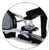

DE ELLIPTICAL VERPLAATSEN
text_image
Technical diagram of a mechanical exercise machine with numbered components and labeled partsMONTAGEMATERIAAL:

BOUT (14) M8 X 20 AANTAL: 4

VEERRING (101) Φ8 AANTAL: 4

SLUITRING (102) Φ8 X Φ20 X 2,5T AANTAL: 4
text_image
Technical diagram of a mechanical device with numbered parts and exploded views, likely for assembly or maintenance instructions.text_image
Technical diagram of a stationary exercise machine with numbered components for identification.text_image
Technical diagram of a stationary exercise machine with numbered components and labeled partsMONTAGEMATERIAAL:

text_image
BOUT (14) M8 X 20 AANTAL: 2 SLUITRING (23) Φ10 X Φ19 X 2T AANTAL: 2 SLUITRING (49) Φ8 X Φ21 X 2T AANTAL: 2 GEGOLFDE VEERRING (13) Φ8 AANTAL: 2 BOUT (41) M10 X 78 AANTAL: 2 MOER (24) M10 AANTAL: 2 EINDKAP (48) AANTAL: 2text_image
Technical diagram of an exercise machine with labeled parts and exploded viewMONTAGEMATERIAAL:
BOUT (46) M8 X 50
AANTAL: 4
VEERRING (53) Φ8
AANTAL: 4

PEDAALKNOP (54) M8 AANTAL: 4

SLUITRING (52) Φ8,5 X Φ16 X 2T AANTAL: 4
text_image
Technical diagram of a mechanical device with numbered components and exploded viewsMONTAGEMATERIAAL:
BUS (20) Φ8 X Φ13 X 35 AANTAL: 1
text_image
Technical diagram of a stationary exercise machine with labeled components and exploded viewMONTAGEMATERIAAL:

BOUT (7)
M4×15
AANTAL: 1
natural_image
Line drawing of an outdoor fitness bike with a mounted digital display and two vertical arms (no text or symbols)MONTAGE VOLTOOID!
SYROS 2.0
SYROS 2.0 CONSOLEDISPLAY

text_image
M W U 00:00 00:00 88.8 88.88 88.8 88.8 88.8 88.8 STRED RPM TIME INSURANCE FAI CALORIES NAST LEVEL FUSH RECOVERY BODY FAT RESET START/STOP MODESYROS 2.0 CONSOLEDISPLAY
A) INTELLIGENT WIEL
Start of stop training.
D) HERSTEL-KNOP
Test hartslagherstelstatus.
E) BODY FAT-KNOP
Test lichaamsvet % en BMI.
F) REK
text_image
M H I I ♥ W UM HANDMATIG
natural_image
Collection of black silhouette icons representing various building types or structures (no text or symbols)text_image
Exploded view diagram of a mechanical device with numbered components and labeled parts, including zoomed-in views and component labels.SYROS 2.0 ONDERDELENLIJST
| NR. | OMSCHRIJVING | AANTAL |
| 1 COMPUTER 1 | ||
| 2 BOVEN COMPUTERKABEL 1 | ||
| 3 SCHROEF M5X10MM 4 | ||
| 4 EINDKAP 2 | ||
| 5 BOVENGREEPSCHUIM 2 | ||
| 6L BOVENGREEP LINKS 1 | ||
| 6R BOVENGREEP RECHTS 1 | ||
| 7 ZELFTAPPENDE SCHROEF 7 | ||
| 8L KUNSTSTOF COMPUTERAFDEKKING LINKS 1 | ||
| 8R KUNSTSTOF COMPUTERAFDEKKING RECHTS 1 | ||
| 9 SCHROEF M5X12MM 7 | ||
| 10L-1 KUNSTSTOF AFDEKKING LINKS VOOR 1 | ||
| 10L-2 KUNSTSTOF AFDEKKING LINKS ACHTER 1 | ||
| 10R-1 | KUNSTSTOF AFDEKKING RECHTS VOOR | 1 |
| 10R-2 | KUNSTSTOF AFDEKKING RECHTS ACHTER | 1 |
| 11 BUS | 6 | |
| 12 SLUITRING | 2 | |
| 13 GEKROMDE RING | 16 | |
| 14 BINNENZESKANTBOUT | 8 | |
| 15 SCHROEF | 4 | |
| 16 VERBINDINGSBUIS ONDER | 2 | |
| 17 GEKROMDE RING | 2 | |
| 18L | KUNSTSTOF AFDEKKING VOOR | 1 |
| 18R | KUNSTSTOF AFDEKKING ACHTER | 1 |
| 19 T-KNOP | 1 | |
| NR. | OMSCHRIJVING | AANTAL |
| 20 BUIS | 1 | |
| 21 CONSOLEMAST | 1 | |
| 22 BUIS | 2 | |
| 23 SLUITRING | 2 | |
| 24 MOER M10 | 3 | |
| 25 SCHROEF M5X15MM 3 | ||
| 26 MOTOR | 1 | |
| 27 MOER M6 | 2 | |
| 28 PEN | 1 | |
| 29 CONUSVEER | 1 | |
| 30 VRIJLOOP-AS SET | 1 | |
| 31 SLUITRING | 2 | |
| 32 SLUITRING | 2 | |
| 33 C-RING | 1 | |
| 34 ZESKANTBOUT | 2 | |
| 35 VEERRING | 2 | |
| 36 MAGNEETSET | 1 | |
| 37 KUNSTSTOF RING | 1 | |
| 38 SLUITRING | 1 | |
| 39 ZESKANTMOER | 1 | |
| 40 BUS | 4 | |
| 41 BINNENZESKANTBOUT | 2 | |
| 42 SCHROEF | 4 | |
| 43L | VOETPLAATAFDEKKING LINKS | 2 |
| 43R | VOETPLAATAFDEKKING RECHTS | 2 |
| 44 EINDKAP 2 | ||
| 45L PEDAALSTANG LINKS 1 | ||
| 45R PEDAALSTANG RECHTS 1 | ||
| 46 BIN NENZESKANTBOUT 4 | ||
| 47L VOETPLAAT LINKS 1 | ||
| 47R VOETPLAAT RECHTS 1 | ||
| 48 EINDKAP 2 | ||
| 49 SLUITRING 2 | ||
| 50 C-RING 2 | ||
| 51 LAGER 2 | ||
| 52 SLUITRING 4 | ||
| 53 VEERRING 4 | ||
| 54 HEX-KNOP 4 | ||
| 55 DECORATIE VOOR RONDE AFDEKKING 2 | ||
| 56L KETTINGAFDEKKING LINKS 1 | ||
| 56R KETTINGAFDEKKING RECHTS | 1 | |
| 57 ZELFTAPPENDE SCHROEF | 6 | |
| 58 SCHROEF | 6 | |
| 59 FLENSMOER | 2 | |
| 60 VERBINDINGSBUIS | 2 | |
| 61 RONDE AFDEKKING | 2 | |
| 62 CRANK | 2 | |
| 63L ACHTERKAP LINKS | 1 | |
| 63R ACHTERKAP RECHTS | 1 | |
| 64 ZELFTAPPENDE SCHROEF | 8 | |
| NR. | OMSCHRIJVING | AANTAL |
| 65 ACHTERSTABILISATIESTANG | 1 | |
| 66 DC-KABEL | 1 | |
| 67 LAGER | 2 | |
| 68 SLUITRING 2 | ||
| 69 GEKROMDE RING | 1 | |
| 70 PEDAALAS | 1 | |
| 71 RIEMWIEL 1 | ||
| 72 BIN NENZESKANTBOUT 4 | ||
| 73 RIEM | 1 | |
| 74 ZELFTAPPENDE SCHROEF | 8 | |
| 75 SLUITRING 8 | ||
| 76 SENSOR | 1 | |
| 77 SENSORKABEL | 1 | |
| 78 BIN NENZESKANTBOUT 1 | ||
| 79 SLUITRING 1 | ||
| 80 VRIJLOOP | 1 | |
| 81 AS VOOR VRIJLOOP | 1 | |
| 82 SLUITRING 1 | ||
| 83 LAGER 1 | ||
| 84 VLIEGWIEL | 1 | |
| 85 VLIEGWIELAS | 1 | |
| 86 ZESKANTMOER | 2 | |
| 87 FLENSMOER | 2 | |
| 88 VERSTELBARE RIEM SET | 2 | |
| 89 LAGER 1 | ||
SYROS 2.0 ONDERDELENLIJST
| NR. | OMSCHRIJVING | AANTAL |
| 90 GEKROMDE RING 3 | ||
| 91 C-RING 2 | ||
| 92 KABEL 1 | ||
| 93 FRAME 1 | ||
| 94 SLUITRING 4 | ||
| 95 GEKROMDE RING 8 | ||
| 96 BINNENZESKANTBOUT 12 | ||
| 97 ONDERSTE COMPUTERKABEL 1 | ||
| 98 KUNSTSTOF AFDEKKING VOORZIJDE 1 | ||
| 99L VOORKAP LINKS 1 | ||
| 99R VOORKAP RECHTS 1 | ||
| 100 VOORSTABILISATOR 13 | ||
| 101 VEERRING 4 | ||
| 102 SLUITRING 4 | ||
| 103 DRAAISTANG | 1 | |
| 104 HANDGREEPPULSKABEL | 2 | |
| 105 ZELFTAPPENDE SCHROEF | 2 | |
| 106 HANDGREEPPULSPAD | 2 | |
| 107 SLEUTEL | 1 | |
| 108 EINDKAP | 2 | |
| 109 HANDGREEP VORM | 2 | |
| 111 BIN NENZESKANTSLEUTEL | 2 | |
| 112 COMBINATIETANG | 1 | |
| 113 ADAPTER | 1 | |
OPTIONS D'ENTRAÎNEMENT

ENTRAÎNEMENT DE LA TOTALITÉ DU CORPS
natural_image
Illustration of a person pushing a small mechanical device with a gear-like component (no text or symbols visible)

DÉPLACEMENT DE L'ÉLLIPTIQUE
text_image
Technical diagram of an exercise bike with labeled components and directional arrows indicating motion or movement.CACHE DE GUIDON SUPÉRIEUR
MÂT DE CONSOLE
ŒILLET DE MÂT DE CONSOLE
BRAS DE PÉDALE
TUBE STABILISATEUR AVANT
BOUTON DE RÉGLAGE DE PÉDALE
OUTILS INCLUS :
text_image
Technical diagram of a mechanical exercise machine with numbered components and labeled partstext_image
Technical diagram of a mechanical device with numbered parts and exploded views, likely for assembly or maintenance instructions.text_image
Technical diagram of a stationary exercise machine with numbered components for identification.text_image
Technical diagram of a stationary exercise machine with numbered components and labeled partstext_image
Technical diagram of an exercise machine with labeled components and parts, including numbered parts and exploded view.text_image
Technical diagram of a mechanical device with numbered components and exploded viewstext_image
Technical diagram of a stationary exercise machine with labeled components and exploded viewnatural_image
Line drawing of a stationary exercise machine with dual arms and control panel (no text or symbols)L'ASSEMBLAGE EST TERMINÉ !
SYROS 2.0
text_image
M H I I ♥ W UM MANUEL
natural_image
Collection of black silhouette icons representing various building types or structures (no text or symbols)text_image
Exploded view diagram of a mechanical device with numbered components and labeled parts, including zoomed-in parts and component labels.LISTE DES PIÈCES SYROS 2.0
| N° | DESCRIPTION | QTÉ |
| 1 ORDINATEUR 1 | ||
| 2 CABLE D'ORDINATEUR SUPERIEUR 1 | ||
| 3 VIS M5X10MM 4 | ||
| 4 EMBOUT D'EXTRÉMITÉ 2 | ||
| 5 MOUSSE DE GUIDON SUPÉRIEUR 2 | ||
| 6L GUIDON SUPÉRIEUR GAUCHE 1 | ||
| 6R GUIDON SUPÉRIEUR DROIT 1 | ||
| 7 VIS AUTOTARAUDEUSE 7 | ||
| 8L COUVERCLE EN PLASTIQUE POUR ORDINATEUR GAUCHE 1 | ||
| 8R COUVERCLE EN PLASTIQUE POUR ORDINATEUR DROIT 1 | ||
| 9 VIS M5X12MM 7 | ||
| 10L-1 COUVERCLE PLASTIQUE GAUCHE AVANT 1 | ||
| 10L-2 COUVERCLE PLASTIQUE GAUCHE ARRIÈRE | 1 | |
| 10R-1 | COUVERCLE PLASTIQUE DROIT AVANT | 1 |
| 10R-2 | COUVERCLE PLASTIQUE DROIT ARRIÈRE | 1 |
| 11 BAGUE | 6 | |
| 12 RONDELLE PLATE | 2 | |
| 13 RONDELLE COURBÉE | 16 | |
| 14 BOULON ALLEN | 8 | |
| 15 VIS | 4 | |
| 16 TUBE DE CONNEXION INFÉRIEUR 2 | ||
| 17 RONDELLE COURBÉE | 2 | |
| 18L | COUVERCLE PLASTIQUE AVANT | 1 |
| 18R | COUVERCLE PLASTIQUE ARRIÈRE | 1 |
| 19 BOUTON EN FORME DE T | 1 | |
| N° | DESCRIPTION | QTÉ |
| 20 | TUBE | 1 |
| 21 | MÂT DE CONSOLE | 1 |
| 22 | TUBE | 2 |
| 23 | RONDELLE PLATE | 2 |
| 24 | ÉCROU M10 | 3 |
| 25 | VIS M5X15MM | 3 |
| 26 | MOTEUR | 1 |
| 27 | ÉCROU M6 | 2 |
| 28 | GOUJON | 1 |
| 29 | RESSORT CONIQUE | 1 |
| 30 | ESSIEU DE JEU DE ROULEAU TENDEUR | 1 |
| 31 | RONDELLE PLATE | 2 |
| 32 | RONDELLE PLATE | 2 |
| 33 | RONDELLE EN FORME DE C | 1 |
| 34 | BOULON HEXAGONAL | 2 |
| 35 | RONDELLE ÉLASTIQUE | 2 |
| 36 | ENSEMBLE D'AIMANTS | 1 |
| 37 | RONDELLE EN PLASTIQUE | 1 |
| 38 | RONDELLE PLATE | 1 |
| 39 | ÉCROU HEXAGONAL | 1 |
| 40 | BAGUE | 4 |
| 41 | BOULON ALLEN | 2 |
| 42 | VIS | 4 |
| 43L CACHE DE REPOSE-PIEDS GAUCHE | 2 | |
| 43R CACHE DE REPOSE-PIEDS DROIT | 2 | |
| 44 EMBOUT D'EXTRÉMITÉ 2 | ||
| 45L BARRE DE PÉDALE GAUCHE 1 | ||
| 45R BARRE DE PÉDALE DROITE 1 | ||
| 46 BOULON ALLEN 4 | ||
| 47L REPOSE-PIEDS GAUCHE 1 | ||
| 47R REPOSE-PIEDS DROIT 1 | ||
| 48 EMBOUT D'EXTRÉMITÉ 2 | ||
| 49 RONDELLE PLATE 2 | ||
| 50 RONDELLE EN FORME DE C 2 | ||
| 51 ROULEMENT 2 | ||
| 52 RONDELLE PLATE 4 | ||
| 53 RONDELLE ÉLASTIQUE 4 | ||
| 54 BOUTON HEXAGONAL 4 | ||
| 55 DÉCORATION POUR COUVERCLE ROND 2 | ||
| 56L CACHE DE CHAÎNE GAUCHE | 1 | |
| 56R CACHE DE CHAÎNE DROIT | 1 | |
| 57 VIS AUTOTARAUDEUSE | 6 | |
| 58 VIS | 6 | |
| 59 ÉCROU À COLLERETTE | 2 | |
| 60 TUBE DE CONNEXION | 2 | |
| 61 COUVERCLE ROND | 2 | |
| 62 MANIVELLE | 2 | |
| 63L EMBOUT ARRIÈRE GAUCHE 1 | ||
| 63R EMBOUT ARRIÈRE DROIT | 1 | |
| 64 VIS AUTOTARAUDEUSE | 8 | |
| N° | DESCRIPTION | QTÉ |
| 65 BARRE | STABILISATRICE ARRIÈRE1 | |
| 66 CÂBLE CC | 1 | |
| 67 ROULEMENT | 2 | |
| 68 RONDELLE PLATE 2 | ||
| 69 RONDELLE COURBÉE | 1 | |
| 70 ESSIEU DE PÉDALE | 1 | |
| 71 ROUE DE COURROIE | 1 | |
| 72 BOULON ALLEN 4 | ||
| 73 COURROIE | 1 | |
| 74 VIS AUTOTARAUDEUSE | 8 | |
| 75 RONDELLE PLATE 8 | ||
| 76 CAPTEUR | 1 | |
| 77 CÂBLE DE CAPTEUR | 1 | |
| 78 BOULON ALLEN 1 | ||
| 79 RONDELLE PLATE 1 | ||
| 80 ROULEAU TENDEUR | 1 | |
| 81 ESSIEU POUR ROULEAU TENDEUR | 1 | |
| 82 RONDELLE PLATE 1 | ||
| 83 ROULEMENT 1 | ||
| 84 VOLANT | 1 | |
| 85 ESSIEU DE VOLANT | 1 | |
| 86 ÉCROU HEXAGONAL | 2 | |
| 87 ÉCROU À COLLERETTE | 2 | |
| 88 ENSEMBLE RÉGLABLE DE COURROIE | 2 | |
| 89 ROULEMENT 1 | ||
LISTE DES PIÈCES SYROS 2.0
| N° | DESCRIPTION | QTÉ |
| 90 RONDELLE COURBÉE 3 | ||
| 91 RONDELLE EN FORME DE C 2 | ||
| 92 CÂBLE 1 | ||
| 93 CADRE 1 | ||
| 94 RONDELLE PLATE 4 | ||
| 95 RONDELLE COURBÉE 8 | ||
| 96 BOULON ALLEN 12 | ||
| 97 CÂBLE D'ORDINATEUR INFÉRIEUR 1 | ||
| 98 CACHE PLASTIQUE DU MONTANT PRINCIPAL 1 | ||
| 99L EMBOUT AVANT GAUCHE 1 | ||
| 99R EMBOUT AVANT DROIT 1 | ||
| 100 BARRE STABILISATRICE AVANT 1 | ||
| 101 RONDELLE ÉLASTIQUE 4 | ||
| 102 RONDELLE PLATE 4 | ||
| 103 TIGE DE ROTATION | 1 | |
| 104 CÂBLE DE PULSATION SUR POIGNÉE | 2 | |
| 105 VIS AUTOTARAUDEUSE | 2 | |
| 106 COUSSINET DE PULSATION SUR POIGNÉE | 2 | |
| 107 CLÉ | 1 | |
| 108 EMBOUT D'EXTRÉMITÉ | 2 | |
| 109 FORME DE GUIDON | 2 | |
| 111 CLÉ ALLEN | 2 | |
| 112 CLÉ COMBINÉE | 1 | |
| 113 ADAPTATEUR | 1 | |
EN : Waste Disposal
VISION Fitness / HORIZON Fitness / TEMPO Fitness / TREO Fitness products are recyclable. At the end if its useful life please dispose of this article correctly and safely (local refuse sites).
Horizon Syros 2.0 | Rev. 1.0 A ©2020 Johnson Health Tech