
VODLT1B2 - Wall mount SANUS - Free user manual and instructions
Find the device manual for free VODLT1B2 SANUS in PDF.

| Product Type | TV Wall Mount |
| Brand | Sanus |
| Model | VODLT1B2 |
| TV Compatibility | Flat screens from 32 to 75 inches (81 to 191 cm) |
| Maximum Load Capacity | 59 kg (130 lb) |
| Material | Robust Steel |
| Color | Black |
| Dimensions (W x H x D) | Approximately 550 x 200 x 30 mm (not exactly provided) |
| Mount Weight | Approximately 3.2 kg (estimate) |
| Compatible Wall Types | Wood studs, solid concrete, concrete block |
| Distance from Wall | Low profile, sits close to wall |
| Tilt | Yes, tension adjustable |
| Lateral Shift | Yes, horizontal sliding |
| Easy Lift Feature | Yes, click lock |
| VESA Standards | VESA compatible (up to 600x400 mm) |
| Support | Phone and email available |
| Package Contents | Wall plate, TV brackets, hardware, instructions |
| Maintenance | Clean with a soft dry cloth |
| Repairability | Spare parts available via customer service |
| Safety | Do not exceed maximum load; install on solid structure |
Frequently Asked Questions - VODLT1B2 SANUS
User questions about VODLT1B2 SANUS
0 question about this device. Answer the ones you know or ask your own.
Ask a new question about this device
Download the instructions for your Wall mount in PDF format for free! Find your manual VODLT1B2 - SANUS and take your electronic device back in hand. On this page are published all the documents necessary for the use of your device. VODLT1B2 by SANUS.
USER MANUAL VODLT1B2 SANUS
natural_image
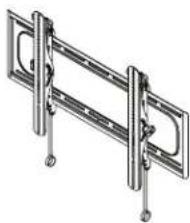
Technical line drawing of a mechanical clamp or bracket assembly (no text or symbols)VODLT1-B2
INSTRUCTION MANUAL
We'll Make It Stress-Free
If you have any questions along the way, just give us a call.
P: +1 (800) 359-5520 · UK: +44 (0) 800 056 2853 · EMEA: +31 (0) 495 580 852
We're ready to help!
IMPORTANT SAFETY INSTRUCTIONS - SAVE THESE INSTRUCTIONS - PLEASE READ ENTIRE MANUAL PRIOR TO USE
Before getting started, let's make sure this mount is perfect for you!
1
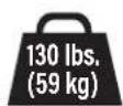
Does your TV (including accessories) weigh MORE than?
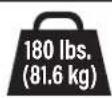
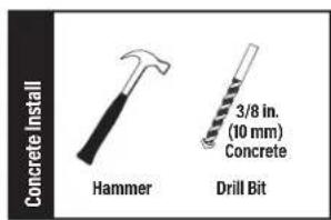
For walls with wood studs, solid concrete or concrete block.
For walls with steel studs.
No - Perfect!
Yes – This mount is NOT compatible. Visit MountFinder.Sanus.com or call +1 (800) 359-5520 (EMEA: +31 (0) 495 580 852; UK: +44 (0) 800 056 2853) to find a compatible mount.
2
What is your wall made of?
wood studs?
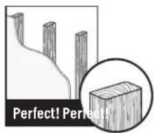
Solid concrete or concrete block?
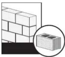
natural_image
Diagram showing a brick wall and a magnified inset of a concrete block (no text or symbols)Drywall with steel studs?
Unsure?Drywall with

Call Customer Service: +1 (800) 359-5520
(EMEA: +31 (0) 495 580 852; UK: +44 (0) 800 056 2853)
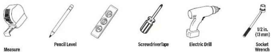
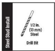
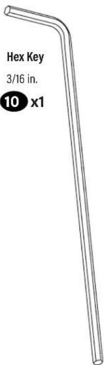
3 Do you have all the tools needed?
4 Ready to begin?
Please read through these instructions completely to be sure you're comfortable with this easy install process. Also check your TV owner's manual to see if there are any special requirements for mounting your TV.
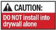
CAUTION: Avoid potential personal injuries and property damage!
- This product includes directions and hardware for use with wood stud, solid concrete, concrete block, steel walls – DO NOT install into drywall alone. For information on how to use this product with steel stud walls contact Customer Service and ask about the steel stud mounting kit.
● The wall must be capable of supporting four times the weight of the TV and mount combined. - Do not use this product for any purpose not explicitly specified by manufacturer.
● Manufacturer is not responsible for damage or injury caused by incorrect assembly or use.
WE'RE HERE TO HELP
natural_image
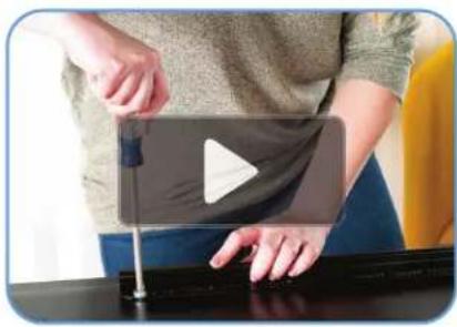
Person using a play button on a black surface, no visible text or symbolsWant to watch a video that shows how easy this DIY project will be?

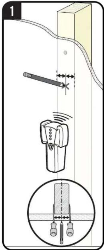
Get it right the first time. HeightFinder™ shows you where to drill.

natural_image
Group of employees in a modern office environment, one wearing headset, seated at workstations (no visible text or signage)Our US-based install experts are standing by to help.

Watch it now at: SANUS.com/3122

Check it out at: SANUS.com/2567
Call us at: US: +1 (800) 359-5520 EMEA: +31 (0) 495 580 852 UK: +44 (0) 800 056 2853
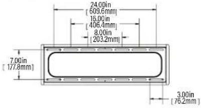
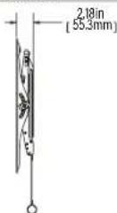
Dimensions
TV INTERFACE
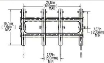
WALL PLATE
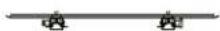
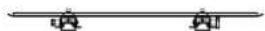
FULLY ASSEMBLED MOUNT
![30.00in [762mm] 22.93in [582.4mm]](/content/2026/04/628229/images/d3b520dce5010cf9f87e9e7aaac690763c07234841594f898cfb9eb524a7b591.jpg)
TOP VIEW - TV MOUNTED
SIMULATED 65° FLAT SCREEN TV
TOP VIEW
3-D
natural_image
Technical illustration of a mechanical support bracket with mounting holes and mounting feet (no text or symbols)SIDE VIEW - TILT
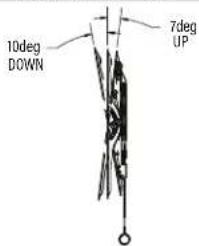
SIDE VIEW
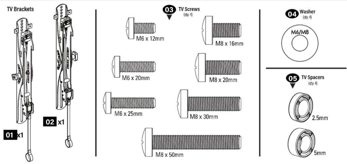
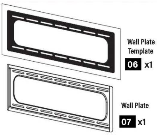
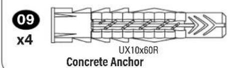
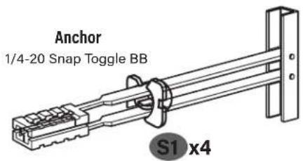
Parts and Hardware
WARNING: This product contains small items that could be a choking hazard if swallowed.
Before starting assembly, verify all parts are included and undamaged. If any parts are missing or damaged, do not return the damaged item to your dealer; contact Customer Service. Never use damaged parts!
NOTE: Not all hardware included will be used.
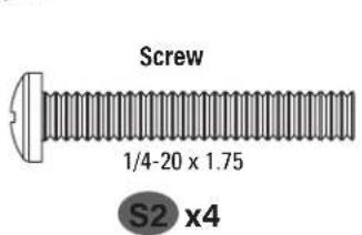
Parts and Hardware for STEP 1
Parts and Hardware for STEP 2
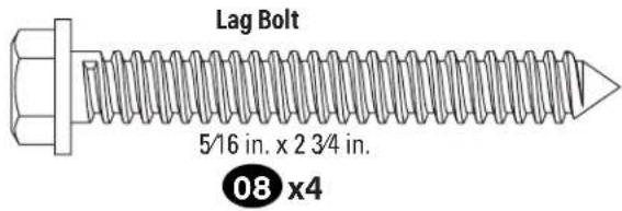
For concrete installations ONLY
Hardware for STEP 2C Steel Stud Option [Steel Stud Anchor Kit is NOT INCLUDED]
Contact Customer Service: +1 (800) 359-5520 (US), +31 (0) 495 580 852 (EMEA), or +44 (0) 800 056 285 (UK) to have the additional hardware shipped directly to you.
![SANUS VODLT1B2 - Hardware for STEP 2C Steel Stud Option [Steel Stud Anchor Kit is NOT INCLUDED] - 3](/content/2026/04/628229/images/110e0b95da304ed31bd8703bcad6db29d0a7d787b42512b2fcab5eab42ee8b1d.jpg)
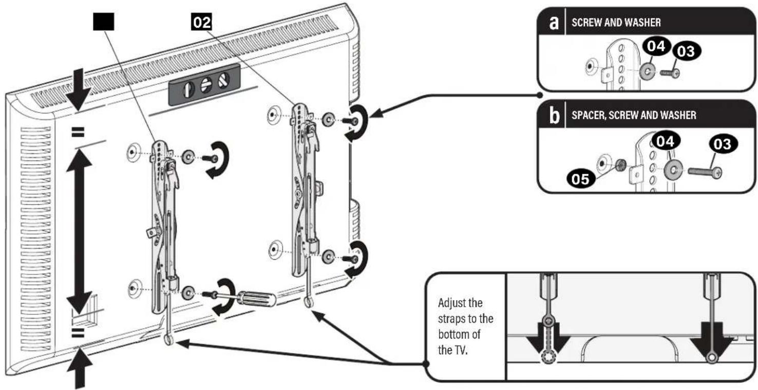
STEP 1 Attach Brackets to TV
1.1 Screw Diameter 1.2 Determine Spacers and Screw Length
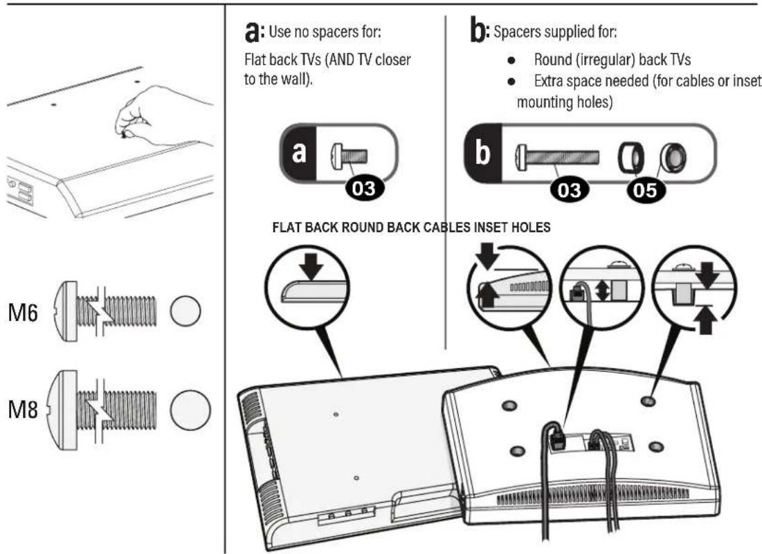
a: Use no spacers for:
Flat back TVs (AND TV closer to the wall).
b: Spacers supplied for:
• Round (irregular) back TVs
- Extra space needed (for cables or inset mounting holes)
For TVs with supplied spacers, verify
adequate thread engagement with the screw and spacer.
M8 screws can be used without the washer for extra thread engagement
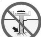
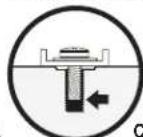
CAUTION: Verify adequate thread engagement with the screw or screw/spacer.
- Too short will not hold the TV.
- Too long will damage the TV.
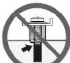
▲ Too Short Too Long

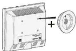
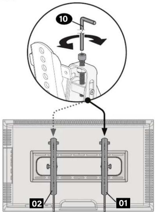
1.3 Attach TV Brackets
Center the TV brackets 01 and 02 horizontally and vertically, and install using your screw/washer/spacer.
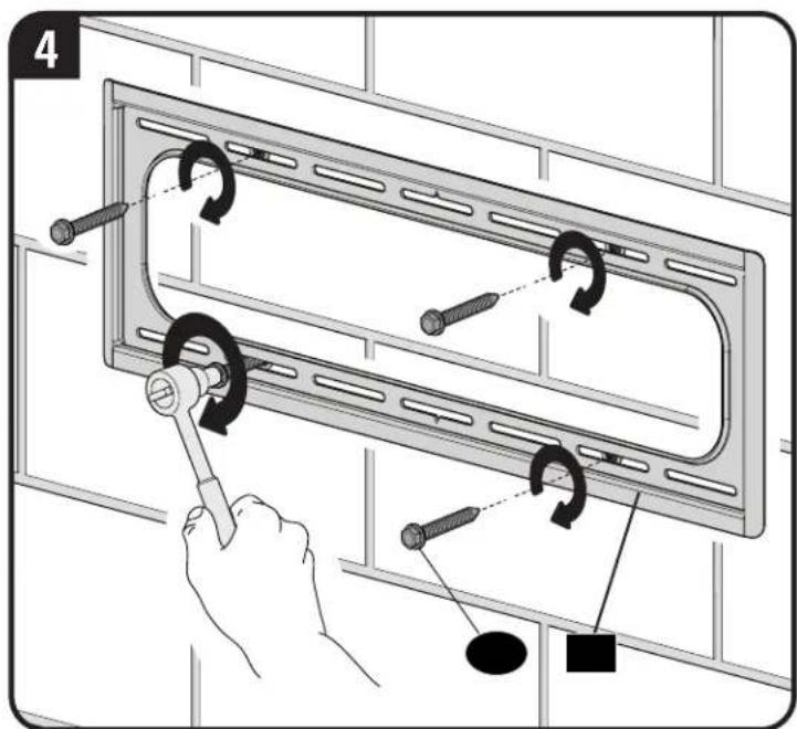
STEP 2A Attach Wall Plate to Wall
Wood Stud Option
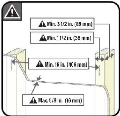
CAUTION: Avoid potential personal injuries and property damage!
- Drywall covering the wall must not exceed 5/8 in. (16 mm)
- Minimum wood stud size: nominal 2 x 4 in. (51 x 102 mm) actual 1½ x 3½ in. (38 x 89 mm)
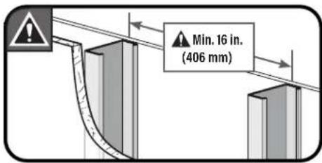
• Minimum horizontal space between fasteners: 16 in. (406 mm)
• Stud centers must be verified
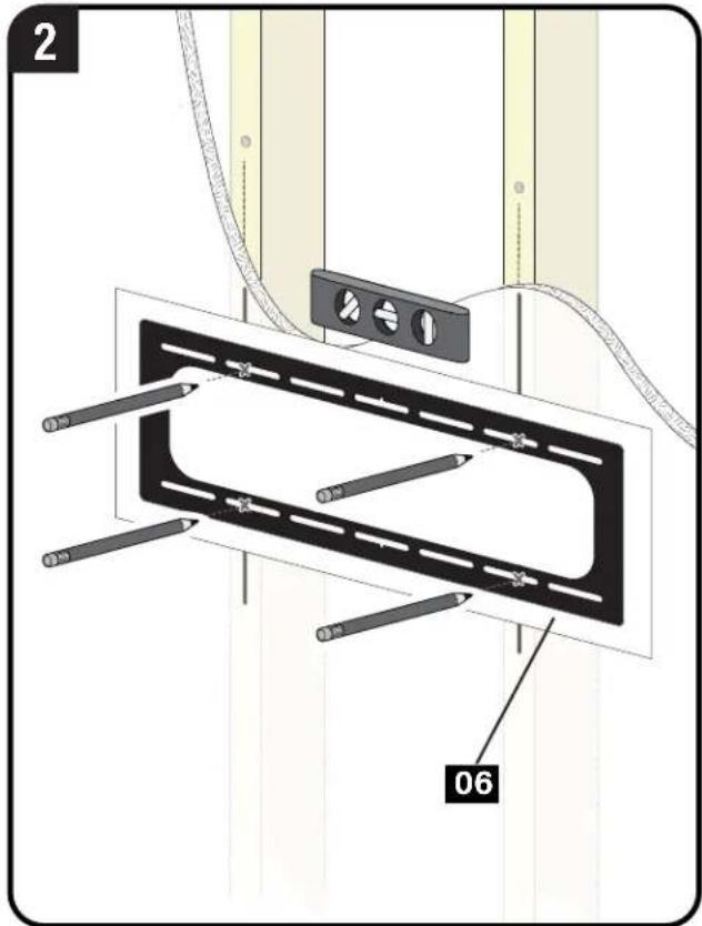
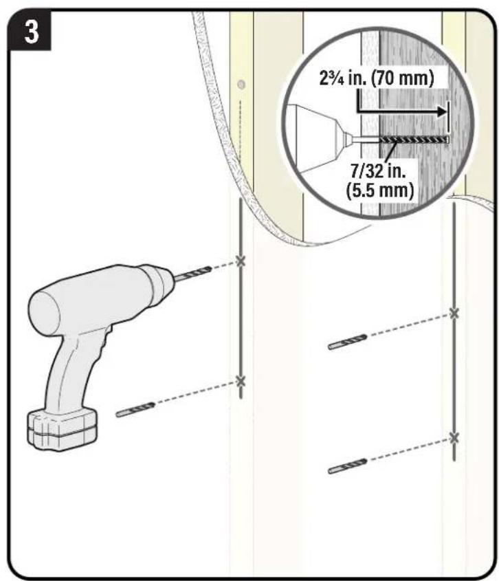
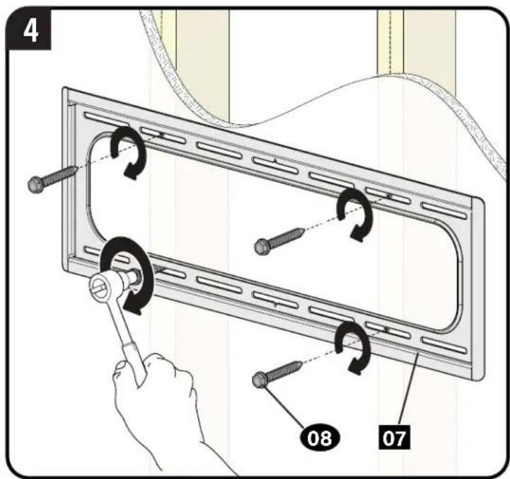
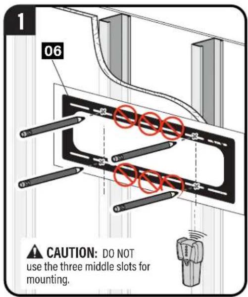
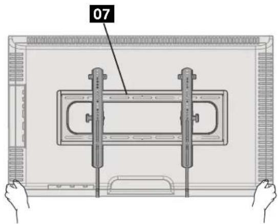
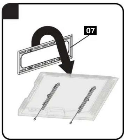
CAUTION: Avoid potential personal injury or property damage! All four lag bolts 08 MUST BE firmly tightened to prevent unwanted movement of the wall plate 07
Go to STEP 3 on PAGE 16.
STEP 2B Attach Wall Plate to Wall
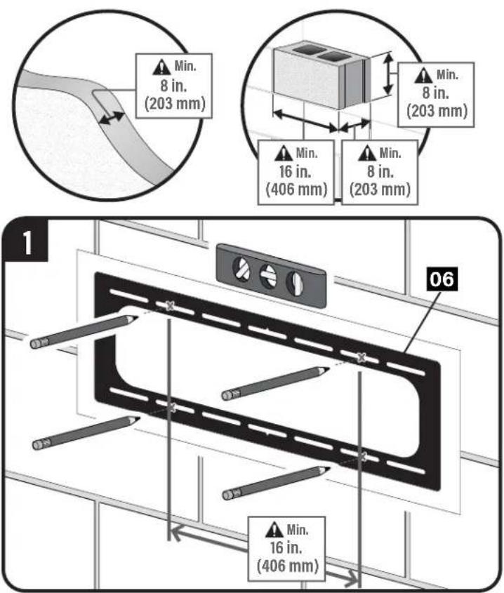
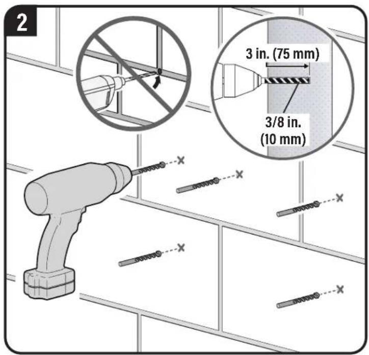
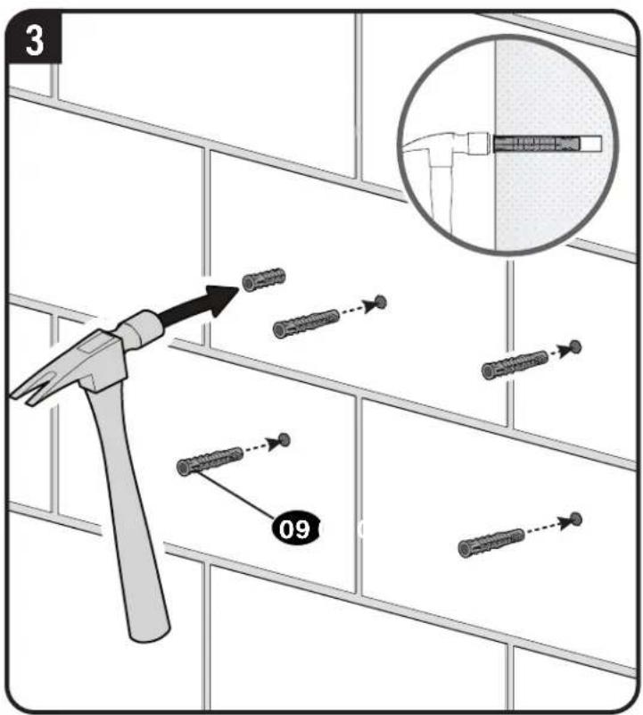
Solid Concrete or Concrete Block Option
CAUTION: Avoid potential personal injuries and property damage! Mount the wall plate 07 directly onto the concrete surface.
CAUTION: Avoid potential personal injury or property damage! All four lag bolts 08 MUST BE firmly tightened to prevent unwanted movement of the wall plate 07. Go to STEP 3 on PAG
Go to STEP 3 on PAGE 16.
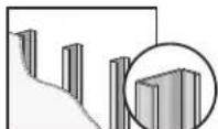
STEP 2C Attach Wall Plate to Wall
Steel Stud Option
Steel Stud Anchor Kit is NOT INCLUDED
Contact Customer Service:
US: +1 (800) 359-5520
EMEA: +31 (0) 495 580 852
UK: +44 (0) 800 056 285
to have the additional hardware shipped directly to you..
CAUTION: Avoid potential personal injuries and property damage!
• Studs must be at least 2x4 / 25 ga.
- If back side of wall is unfinished, drywall must be installed to a minimum of one stud left and right of the stud(s) being used to install the mount.
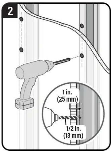
- Drywall must be a minimum of 1/2 in. (13 mm) thick on each side of the studs, and a minimum clearance of 17/8 in. (48 mm)
behind the wall is required.
• This product must be centered on the studs.
- Stud type and structural strength must conform to the North American Specification for the Design of Cold-Formed Steel Structural Members [362 S 125 18, C-Shape, S - Stud Section].
- Drywall must be secured to studs with screws 12 in. (304.8 mm) on center.
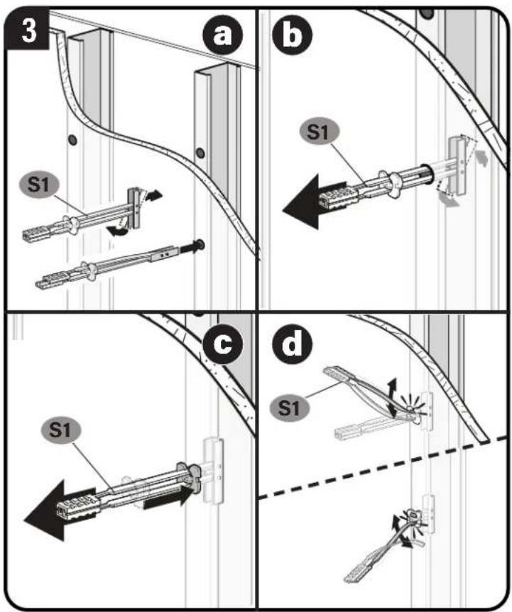
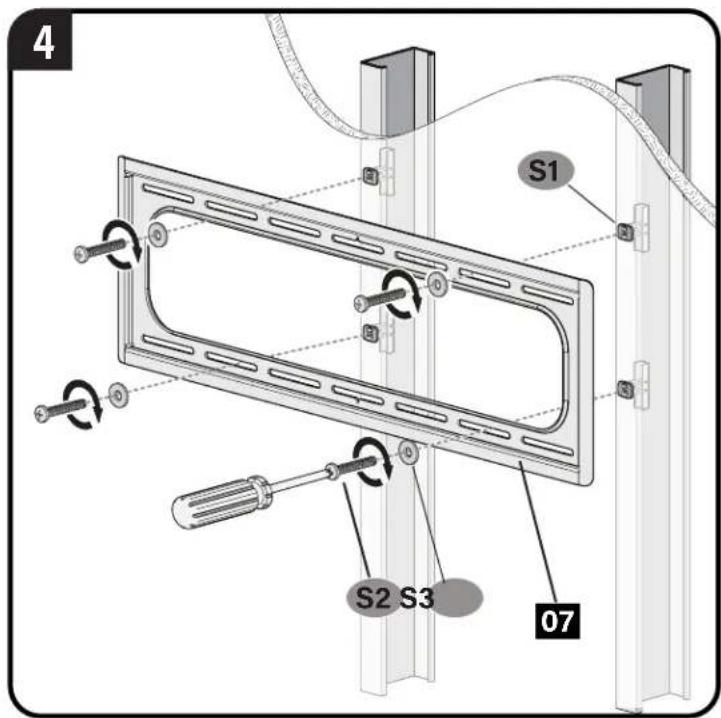
CAUTION: Avoid potential personal injury or property damage! All four screws S2 MUST BE firmly tightened to prevent unwanted movement of the wall plate 07.
STEP 3 Attach TV to Wall Plate

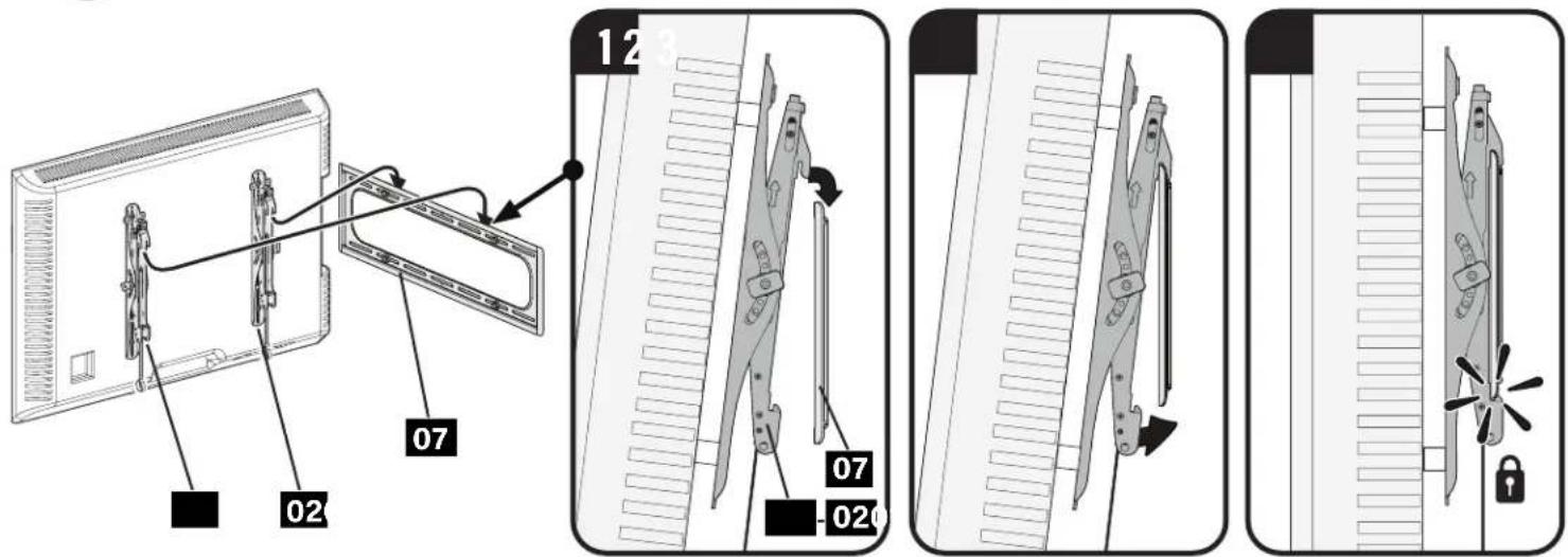
CAUTION: Avoid potential personal injury or property damage!
Always make sure your TV brackets 01 and 02 are in the locked position so the TV is securely fastened to the wall plate 07.
Adjustments
LEVEL HEIGHT
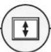
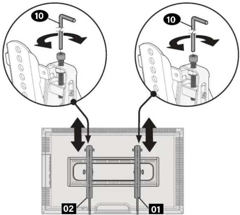
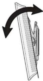
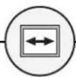
TILT TV LATERAL SHIFT
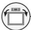
Your TV should adjust easily when moved, then stay in place.
Adjust the tilt tension knob Ⓣ if your TV naturally tilts up or down.
NOTE: If you do not intend to adjust the tilt for different viewing locations, you can tighten the tilt tension knobs Ⓣ to prevent unwanted movement.
natural_image
Diagram of a ruler measuring a surface with directional arrows indicating measurement (no text or symbols)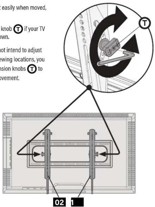

CAUTION: Avoid potential personal injury or property damage!
Slowly slide the TV along the wall plate to reposition. The wall plate has built-in stops to limit lateral movement.
REMOVING THE TV

NOTE: To rehang the TV, follow the procedures in STEP 3 on PAGE 16.

natural_image
Diagram of a mounted device with two vertical connectors and a curved cable, showing no text or symbols.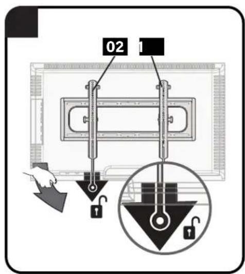
Español
m = 311
中
m = 311
4
¿Preparado para
empezar?
natural_image
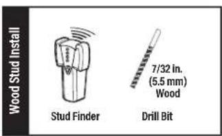
Illustration of a brick wall and a magnified inset showing a small block (no text or symbols)コンクリートまたはコンクリートブロック
鋼製スタッドと石膏ボード

A brand of □ legrand
Thank you for choosing SANUS! Please take a moment to let us know how we did:
Legrand AV Inc.
6436 City West Parkway
Eden Prairie, MN 55344 USA
US: +1 (800) 359-5520
Legrand AV Netherlands B.V.
Franklinstraat 14
6003 DK Weert Netherlands
EMEA: +31 (0) 495 580 852
UK: +44 (0) 800 056 2853
Authorized Representative for the UK
Starline Holding Technology Ltd.
Unit C Island Road
Reading RG2 ORP UK
Legrand AV Inc. and its affiliated corporations and subsidiaries (collectively, "Legrand"), intend to make this manual accurate and complete. However, Legrand AV makes no claim that the information contained herein covers all details, conditions, or variations. Nor does it provide for every possible contingency in connection with the installation or use of this product. The information contained in this document is subject to change without notice or obligation of any kind. Legrand AV makes no representation of warranty, expressed or implied, regarding the information contained herein. Legrand AV assumes no responsibility for accuracy, completeness or sufficiency of the information contained in this document.
©2022 Legrand AV Inc. All rights reserved. SANUS is a brand of Legrand.
All other brand names or marks are used for identification purposes and are trademarks of their respective owners.
Legrand AV Inc. · 6436 City West Parkway · Eden Prairie, MN 55344 USA
6901-603066 00