
VODLF125B2 - Wall mount SANUS - Free user manual and instructions
Find the device manual for free VODLF125B2 SANUS in PDF.

| Product Type | Articulating Wall Mount |
| Brand | SANUS |
| Model | VODLF125B2 |
| Maximum TV Weight | 54,4 kg (120 lb) |
| Wall Compatibility | Wood studs (2x4 in nominal), solid concrete (20,3 cm min), concrete blocks (20,3x20,3x40,6 cm min) |
| Tilt | Adjustable via tilt screws |
| Height Adjustment | Yes, with locking screw |
| Arm Extension | Yes, with adjustable range |
| Cable Management | Integrated |
| Material | Steel |
| Finish | Black |
| Screws Included | Yes, multiple sizes for different TV thicknesses |
| Tools Required | Screwdriver, drill, level, socket wrench, stud finder (for wood), wood drill bit (7/32 in) or concrete drill bit (3/8 in) |
| Warranty | 5 years (estimated) |
| Phone Support | US: +1-800-359-5520, EMEA: +31 (0) 495 580 852, UK: 0800 056 2853 |
| Safety | Do not exceed max weight, installation on suitable wall, proper tightening of screws |
Frequently Asked Questions - VODLF125B2 SANUS
User questions about VODLF125B2 SANUS
0 question about this device. Answer the ones you know or ask your own.
Ask a new question about this device
Download the instructions for your Wall mount in PDF format for free! Find your manual VODLF125B2 - SANUS and take your electronic device back in hand. On this page are published all the documents necessary for the use of your device. VODLF125B2 by SANUS.
USER MANUAL VODLF125B2 SANUS
natural_image
Technical line drawing of a mechanical assembly with two parallel plates and a central frame (no text or symbols)VODLF125-B2
INSTRUCTION MANUAL
natural_image
Person using a computer to interact with a video player (no visible text or symbols)Want to watch a video that shows how easy this DIY project will be?

Get it right the first time. HeightFinder™ shows you where to drill.

natural_image
Group of employees in a modern office environment, one wearing headset and smiling (no visible text or symbols)Our US-based install experts are standing by to help.

Watch it now at: SANUS.com/3124

Check it out at: SANUS.com/2567

Call us at: US: +1 (800) 359-5520 EMEA: +31 (0) 495 580 852 UK: +44 (0) 800 056 2853
IMPORTANT SAFETY INSTRUCTIONS – PLEASE READ MANUAL PRIOR TO USE – SAVE THESE INSTRUCTIONS
Please read through these instructions completely to be sure you're comfortable with this easy install process.
Check your TV owner's manual to see if there are any special requirements for mounting your TV.
If you do not understand these instructions or have doubts about the safety of the installation, assembly or use of this product, contact Customer Service at +1-800-359-5520 (EMEA: +31 (0) 495 580 852; UK: +44 (0) 800 056 2853).

CAUTION: Avoid potential personal injuries and property damage!
- This product is designed ONLY to be installed into wood studs, solid concrete or concrete block.
— DO NOT INSTALL INTO DRYWALL ALONE — DRYWALL ALONE WILL NOT HOLD THE WEIGHT OF YOUR TV. - The wall must be capable of supporting five times the weight of the TV and mount combined.
- Do not use this product for any purpose not explicitly specified by manufacturer.
- Manufacturer is not responsible for damage or injury caused by incorrect assembly or use.
TV Weight Limit
(including accessories)
DO NOT EXCEED
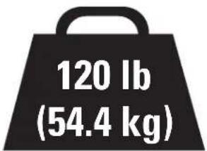
If your TV (including accessories) exceeds this weight, this mount is NOT compatible.
Visit SANUS.com or call customer service to find a compatible mount.
US: +1-800-359-5520
EMEA: +31 (0) 495 580 852
UK: +44 (0) 800 056 2853)
Wall Construction
ONLY install on these acceptable wall types.
Unsure?
Call Customer Service 1-800-359-5520

CAUTION:
DO NOT install in drywall alone
Drywall alone will NOT hold the weight of your TV.
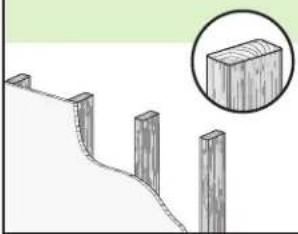
Wood studs
natural_image
Diagram of a wooden fence structure with four posts and a magnified inset showing a rectangular block (no text or symbols)Perfect!
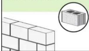
Solid concrete or concrete block
natural_image
Illustration of a brick wall with a magnified inset showing two stacked bricks (no text or symbols)Concrete Anchor Kit #CMK1 is required (not included)
Contact Customer Service to inquire about the CMK1 Concrete Anchor Kit.
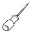
Tools Needed
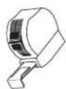

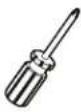
ScrewdriverTape
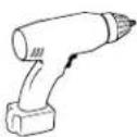
Electric Drill
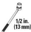
Socket Wrench
Measure
Wood Stud Install
Stud Finder
Awl

Drill Bit
Concrete Install
Drill Bit
Hammer
Dimensions
![TV INTERFACE 23.62in [600mm] MAX 15.75in [400mm] MAX 3.94in [100mm] MIN 3.94in [100mm] MIN](/content/2026/04/628226/images/27ea0bb7ce749934b000eac576686014f1f3deab754f8854677f3a7cff61b084.jpg)
natural_image
Technical line drawing of a mechanical clamp or bracket assembly (no text or symbols)![WALL PLATE 16.00in [406.4mm] 10.36in [263.1mm] 1.77in [45mm]](/content/2026/04/628226/images/44abc829243986cf89d9f27f4b20a2879b29eb88dedc84e5ae48b1a3723fb5bd.jpg)
![TOP VIEW - EXTENDED 25.0in [634mm] 44deg 44deg SIMULATED 65" FLAT SCREEN TV](/content/2026/04/628226/images/ac10aa13d1180d7e2f6423079b7283ac7b397fef932e71988699d45a52d9351c.jpg)
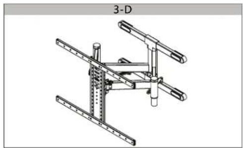
![FULLY ASSEMBLED MOUNT 26.97in [ 585.1mm ] 37.01in [ 432mm ]](/content/2026/04/628226/images/8143850a3821f8bc91b5503bae81b80d0bab04a3952c3a33b0b300f3e1129e4c.jpg)
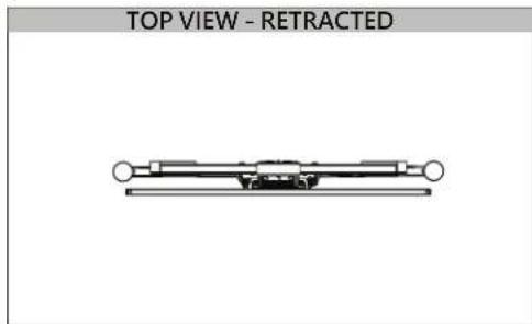
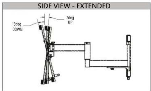
![SIDE VIEW RETRACTED 274in [69.5mm]](/content/2026/04/628226/images/0baee7e647953235d0dd085502d3f60db4cfb4fb74a8b5d72cfcea56bc8d954c.jpg)
BEFORE YOU BEGIN
Supplied Parts and Hardware
WARNING: This product contains small items that could be a choking hazard if swallowed. Before starting assembly, verify all parts are included and undamaged. If any parts are missing or damaged, do not return the damaged item to your retailer; contact Customer Service. Never use damaged parts!

NOTE: Not all hardware included will be used.
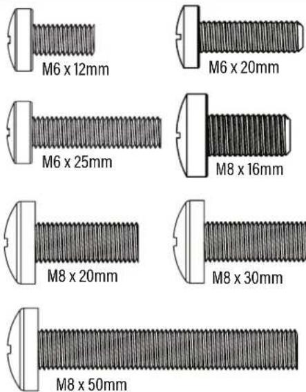
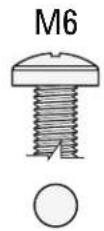
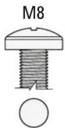
STEP 1 Parts and Hardware
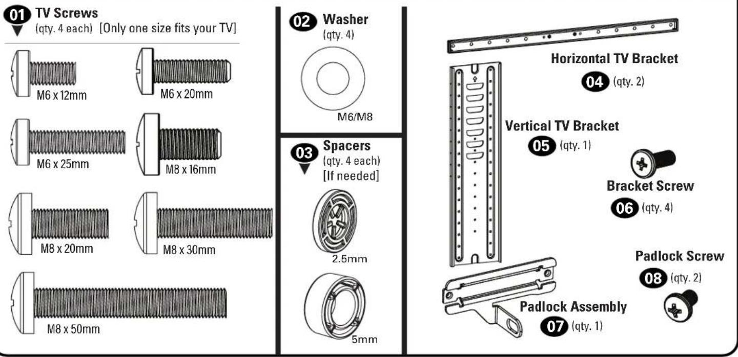
(qty. 4 each) [Only one size fits your TV]
(qty. 4 each) [If needed]
STEP 2 Parts and Hardware
natural_image
Pure electrical circuit lines without any symbolsDrilling Template
09 (qty. 1)
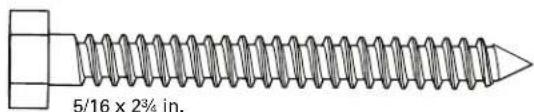
natural_image
Technical line drawing of a mechanical assembly with no visible text or symbolsLag Screw
11(qty.4)
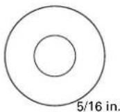
Washer
12(qty.4)
STEP 2B: Concrete Anchor Kit CMK1 [NOT INCLUDED]
Contact Customer Service at 1-800-359-5520 to inquire about the CMK1 Concrete Anchor Kit.
Concrete Anchor
C1(qty.4)
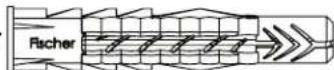
Fischer UX10 x 60R Anchor
STEP 3 Hardware
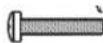
Roll Screw
13(qty.1)

Additional Hardware
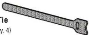
Cable Tie
14 (qty. 4)
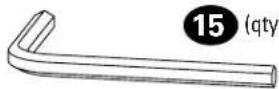
Hex Key
STEP 1 Attach TV Bracket to TV
1.1 Select TV Screw Diameter
Only one screw size fits your TV.

NOTE: If your TVuded inset spacers dapters, use them DER the mount dware.
1.2 Select TV Screw Length and Spacers
A NO SPACER SPACER NE B D
- Flat Back TV
[TV brackets lay flat on your TV]
Use short TV screws 01 Spacers 03 not needed.

- Flat Back TV with extra space needed [for deep inset holes or cable interference]
• Rounded or Irregular Back TV [TV brackets NOT resting flat on your TV]
Use long TV screws 01 and spacers 03 to create extra space between the TV and TV bracket.


CAUTION: Verify adequate thread engagement with your screw 01, washer 02, spacer 03 combination AND TV bracket 04.
— Too short will not hold your TV. — Too long will damage your TV.
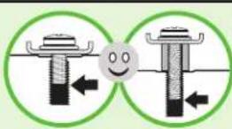
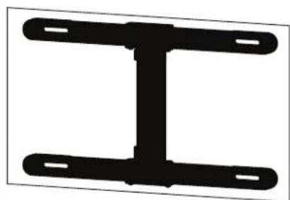
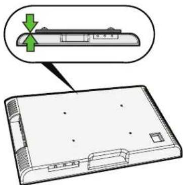
1.3 Attach Horizontal TV Brackets to Your TV
Position vertical TV brackets 04 over your TV hole pattern - making sure the brackets are vertically centered and level. Install using the screw 01/washer 02/spacer 03 combination A or B you selected for your TV.
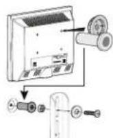
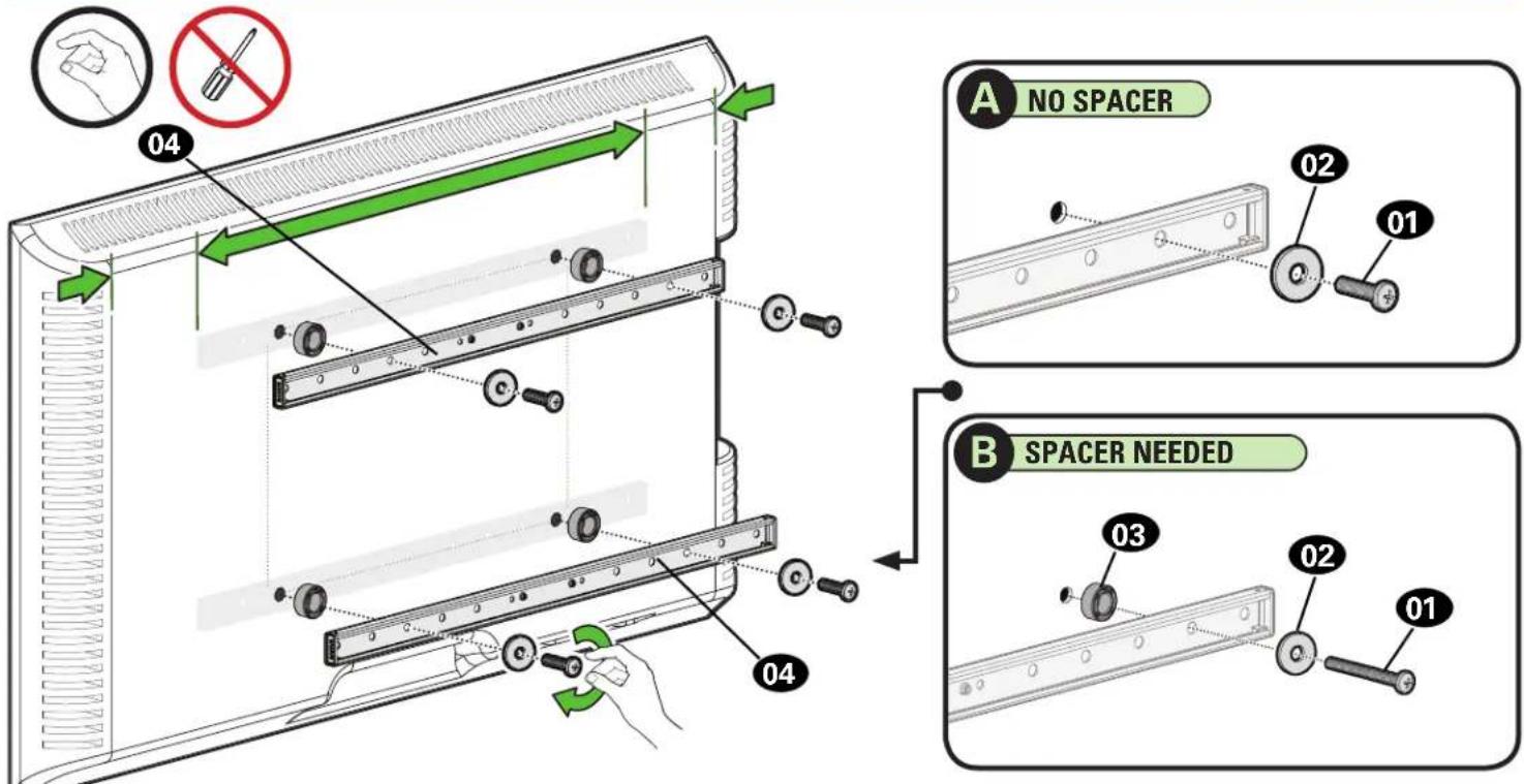
1.4 Attach Vertical TV Bracket to Horizontal Brackets and Tighten All Screws
Position the vertical TV bracket 05 onto the horizontal TV bracket 04 and loosely attach four screws 06.
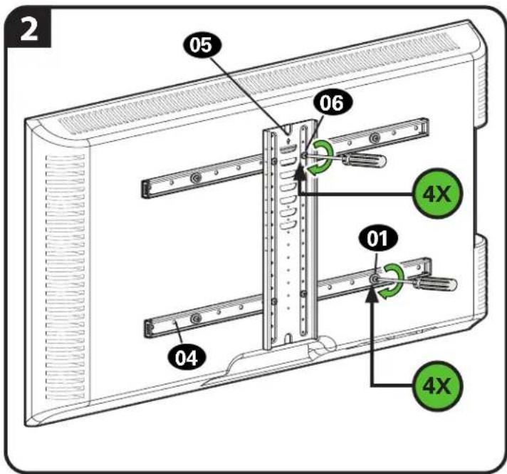
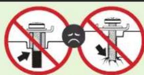
CAUTION: Avoid potential personal injuries and property damage! DO NOT use power tools for this step. Tighten the four TV screws 01 and four vertical TV bracket screws 06 only enough to secure the TV brackets 04 / 05 to the TV.
1.5 Attach Padlock Assembly (optional)
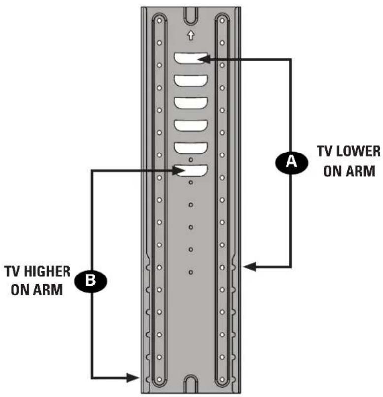
IMPORTANT: Install Padlock Assembly higher to hang your TV lower (see example A), or install lower to hang your TV higher (see example B).
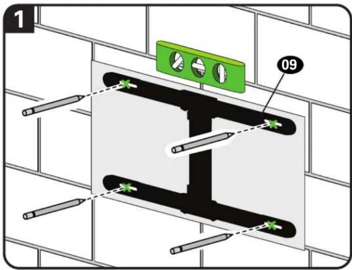
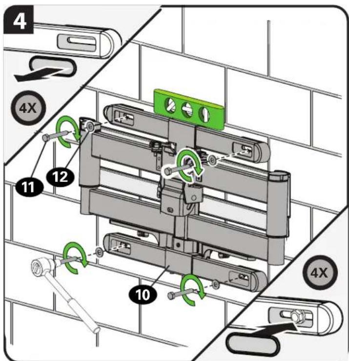
STEP 2A Attach Wall Plate
Wood Stud Installation
CAUTION: Avoid potential personal injury or property damage!
• Drywall covering the wall must not exceed 5/8 in. (16 mm)
● Minimum wood stud size: nominal 2 x 4 in. (51 x 102 mm) actual 1½ x 3½ in. (38 x 89 mm)
• Minimum horizontal space between lag screws: 16 in. (406 mm)
• Stud center must be verified
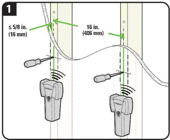
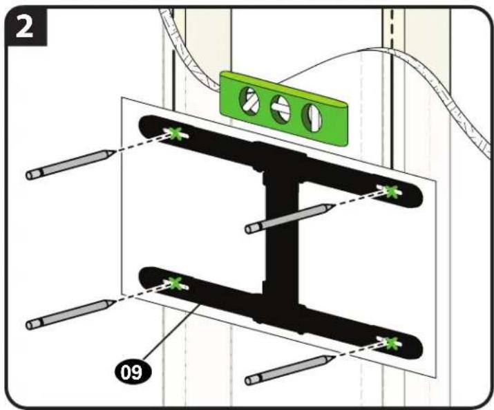
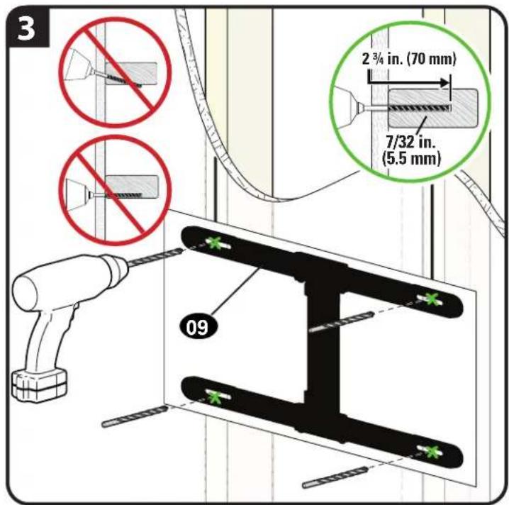
IMPORTANT: Drill into the center of the stud.
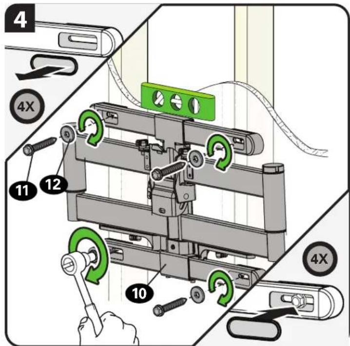
Tighten the lag screws 11 only until the washers 12 are pulled snug against the wall plate 10.
CAUTION: Improper use could reduce the holding power of the lag screw. DO NOT over-tighten the lag screws.
STEP 2B Attach Wall Plate
Solid Concrete or Concrete Block Installation

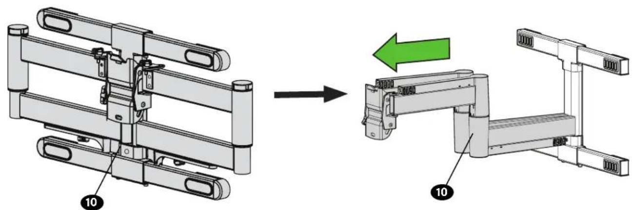
CAUTION: Avoid potential personal injury or property damage!
- Mount arm assembly 10 directly onto concrete surface (no wall covering)
• Minimum solid concrete thickness: 8 in. (203 mm)
• Minimum concrete block size: 8 x 8 x 16 in. (203 x 203 x 406 mm)
Concrete Anchor Kit CMK1 is not included
Contact Customer Service at +1-800-359-5520
(EMEA: +31 (0) 495 580 852; UK: +44 (0) 800 056 2853) to inquire
about the CMK1 Concrete Anchor Kit.
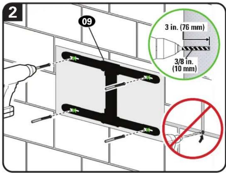
CAUTION: Never drill into the mortar between blocks.
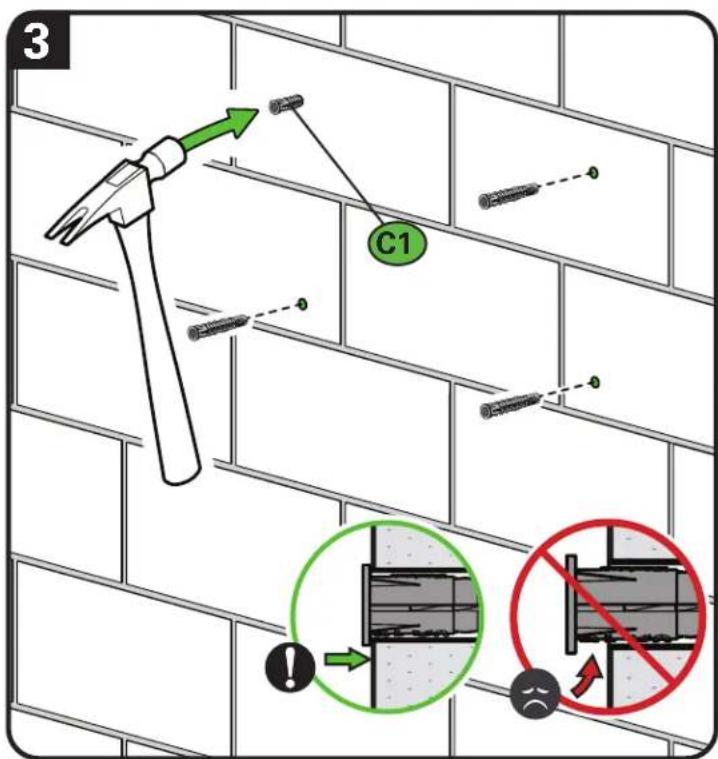
*Contact Customer Service to inquire about Concrete Anchor Kit CMK1 and anchors C1.
Tighten the lag screws 11 only until the washers 12 are pulled snug against the wall plate 10.
CAUTION: Improper use could reduce the holding power of the lag screw. DO NOT over-tighten the lag screws.
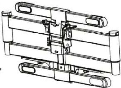
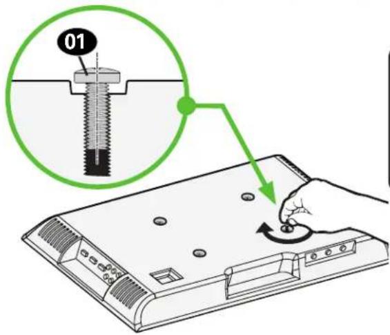
STEP 3 Attach TV to Arm Assembly

HEAVY! You may need assistance with this step.
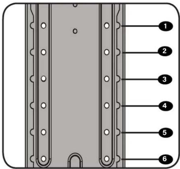
1
Height Adjust Selection
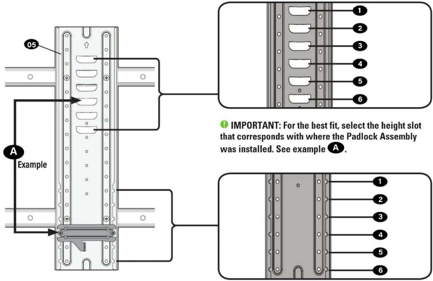
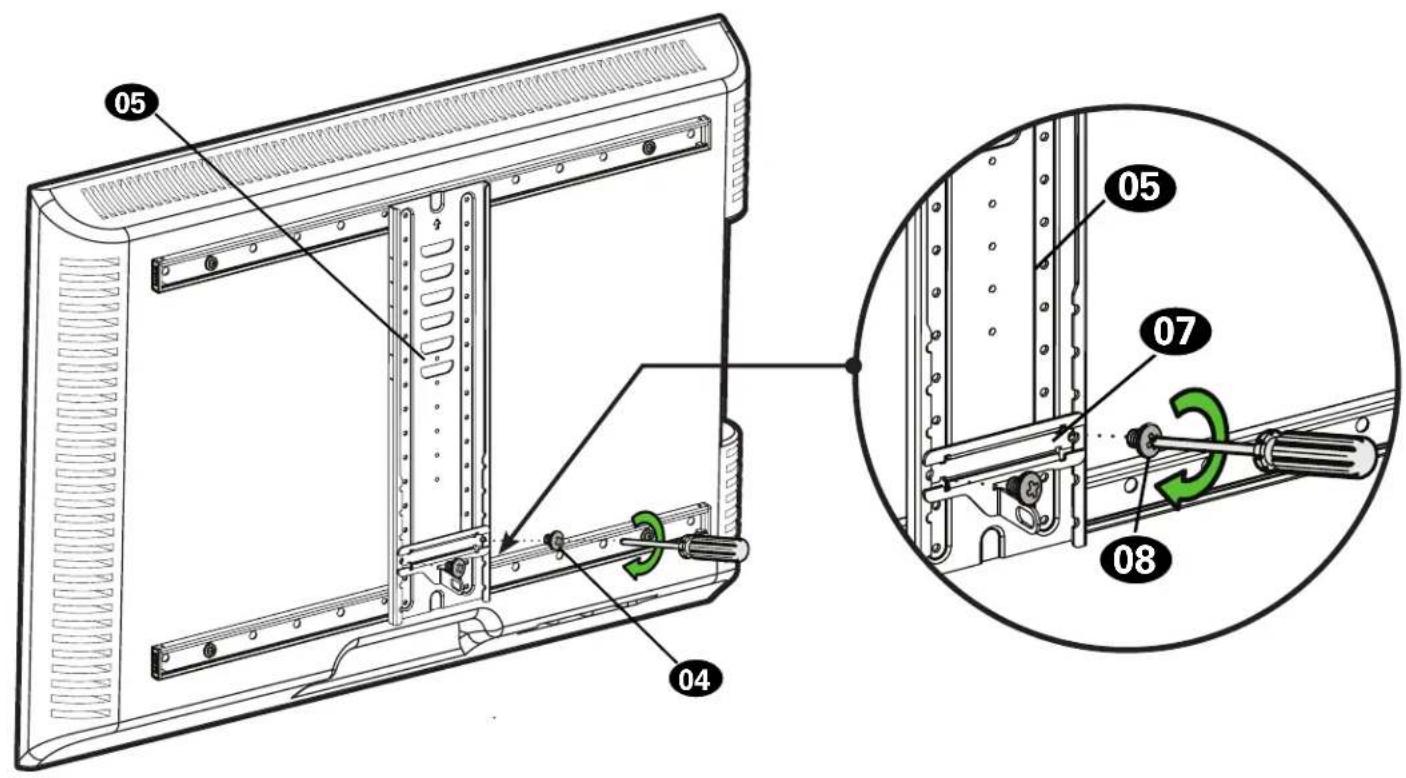
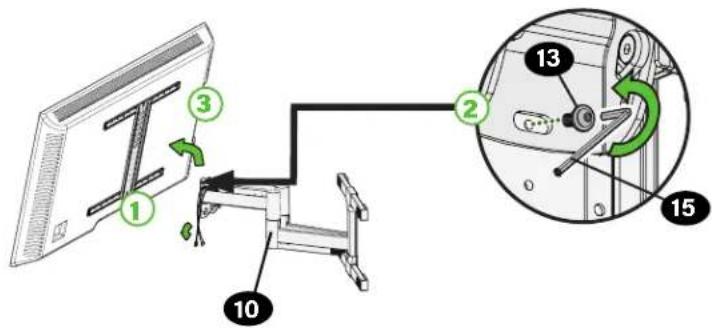
STEP 3 Attach TV to Arm Assembly
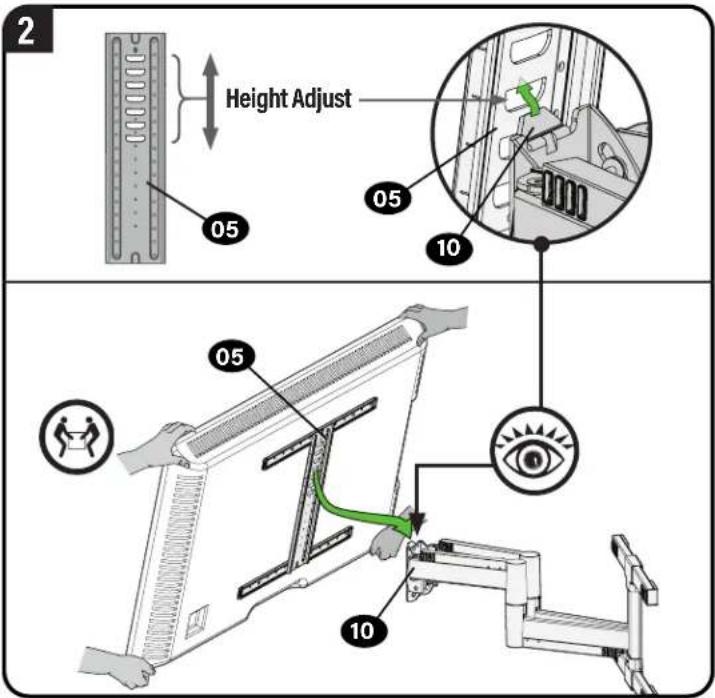
Use two people to hang the TV, to visually ensure TV bracket 05 is hung onto arm assembly 10 at your desired height slot.
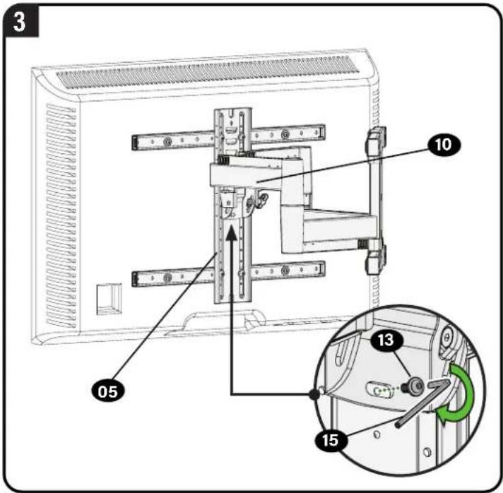
To adjust the leveling of your TV, loosen the roll screw 13, level your TV, then tighten the roll screw 13.
CAUTION: Avoid potential personal injury or property damage! Locking screw 13 must be installed to secure the TV to the arm assembly 10.
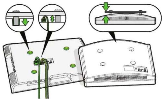
Manage Cables
Fully extend the arms before attaching cables. Use cable ties 14 to secure cables.
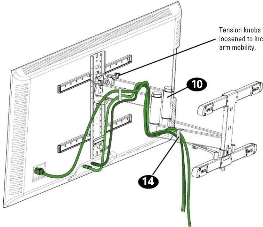
Tension knobs can be tightened or loosened to increase or decrease arm mobility.
Secure TV with Padlock Assembly
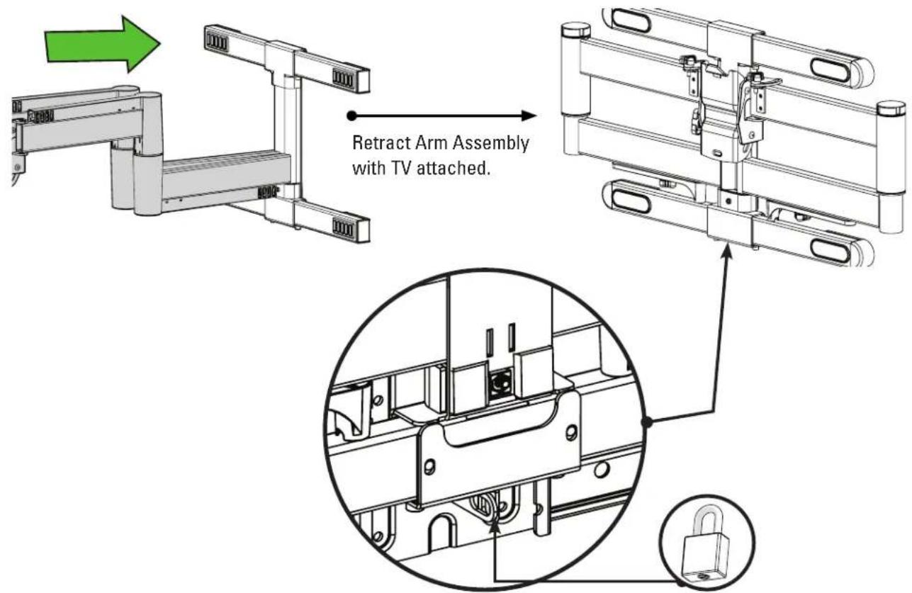
Secure the Padlock Assembly with a padlock to keep TV and mount in place. Packlock should have a minimum shackle of 2½ inches to prevent interference with wall plate.
TV Adjustments

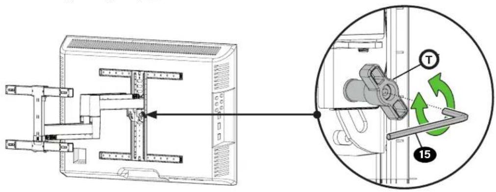
TILT ADJUSTMENT
Your TV should adjust easily when moved, then stay in place. If your TV is too loose or too tight, adjust the side tension knob
NOTE: Once your TV is in place, tighten the tension knob Ⓣ to prevent unwanted movement.
NOTE: Additional tension can be applied using hex key 15.

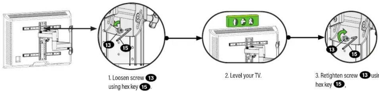
LEVEL ADJUSTMENT
flowchart
graph LR
    A["Initial door panel"] --> B["Loosen screw 13 using hex key 15"]
    B --> C["Level your TV."]
    C --> D["Retighten screw 13 using hex key 15"]
CAUTION: Avoid potential personal injury or property damage! Locking screw 13 must be installed to secure the TV to the arm assembly 10.

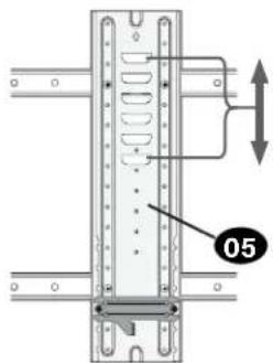
HEIGHT

HEAVY! You may need assistance with this step.
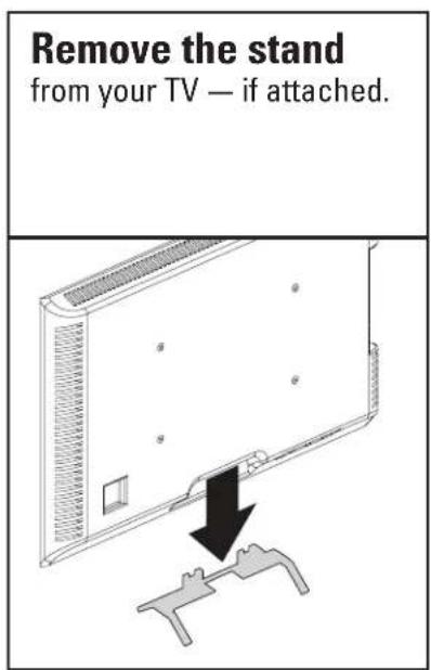
- Remove the TV (see below).
- If Padlock Assembly is installed, remove and reinstall as outlined in STEP 1.5.
- Follow STEP 3 to hang the TV to your new location using the height adjustment slots.
Height Adjust
natural_image
Mechanical assembly diagram showing a mounted device with a green cable (no text or symbols visible)
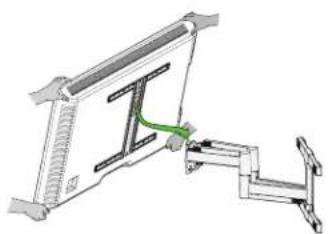
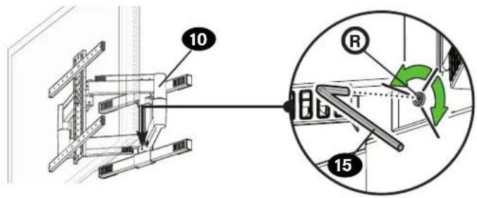
EXTEND / RETRACT -- ONLY IF NECESSARY
Your TV should adjust easily when moved, then stay in place. ONLY if needed, adjust the extension/retraction arm tension with screw using hex key 15.
CAUTION: Avoid potential personal injury or property damage! DO NOT remove bolts Ⓡ, only turn enough for slight adjustment.

REMOVING THE TV

HEAVY! You may need assistance with this step.
- Disconnect cables.
- Remove screw
13 using hex key 15. - Lift TV up and off the arm assembly
10
ESPAÑOL
natural_image
Illustration of five different types of electrical tools or components, including a screwdriver, pushpin, and bulb (no text or symbols present)Thank you for choosing Sanus! Please take a moment to let us know how we did:
Legrand AV Inc.
6436 City West Parkway
Eden Prairie, MN 55344 USA
US: +1 (800) 359-5520
SANUS.com
Legrand AV Netherlands B.V.
Franklinstraat 14
6003 DK Weert Netherlands
EMEA: +31 (0) 495 580 852
UK: +44 (0) 800 056 2853
SANUS.com
Authorized Representative for the UK
Starline Holding Technology Ltd.
Unit C Island Road
Reading RG2 ORP UK
Legrand AV Inc. and its affiliated corporations and subsidiaries (collectively, "Legrand"), intend to make this manual accurate and complete. However, Legrand makes no claim that the information contained herein covers all details, conditions, or variations. Nor does it provide for every possible contingency in connection with the installation or use of this product. The information contained in this document is subject to change without notice or obligation of any kind. Legrand makes no representation of warranty, expressed or implied, regarding the information contained herein. Legrand assumes no responsibility for accuracy, completeness or sufficiency of the information contained in this document.
©2022 Legrand AV Inc. All rights reserved. SANUS is a brand of Legrand. SANUS, HeightFinder, and the Sanus logo are trademarks of Legrand.