
SE1100 - Alarm system ABUS - Free user manual and instructions
Find the device manual for free SE1100 ABUS in PDF.
| Product type | Removable key switch for alarm system |
| Brand | ABUS |
| Model | SE1100 |
| Dimensions (surface mounting) | 85 x 114 x 42 mm (W x H x D) |
| Dimensions (flush mounting) | 106 x 134 x 42 mm (W x H x D) |
| Weight | 450 g |
| LED power supply | 10–15 V DC, 2 mA max per LED |
| Contact rating | 30 V DC / 0.5 A |
| Protection rating | IP55 |
| Number of contacts | 3 (changeover) |
| Mounting type | Surface or flush |
| Main functions | Arming/disarming alarm system, device control, permanent or impulse contact |
| Display | Bi-color LED (red/yellow) |
| Protection | Cover contact, anti-pry wall (surface), cylinder protective rosette |
| Maintenance and cleaning | Clean with a dry, non-abrasive cloth. Do not use chemicals. |
| Safety | Opening and tamper detection, ABUS quality cylinder |
| Spare parts and repairability | Contact ABUS after-sales service for spare parts |
| General information | Compliant with European directives. Supplied with housing screw, hex key, gasket, sealing plate, wall plugs and fixing screws. |
Frequently Asked Questions - SE1100 ABUS
User questions about SE1100 ABUS
0 question about this device. Answer the ones you know or ask your own.
Ask a new question about this device
Download the instructions for your Alarm system in PDF format for free! Find your manual SE1100 - ABUS and take your electronic device back in hand. On this page are published all the documents necessary for the use of your device. SE1100 by ABUS.
USER MANUAL SE1100 ABUS
Thank you for purchasing this surface-fitted/flush-fitting key switch. You made the right decision in choosing this state-of-the-art technology, which complies with the current standards of domestic and European regulations. The CE has been proven and all related certifications are available from the manufacturer upon request. To maintain this status and to guarantee safe operation, it is your obligation to observe these operating instructions.
Notes
The key switch is equipped with a burglary/tamper sensor and is used for switching on or off the alarm system of an entire location or sections of the location.
It can also be used for controlling other electronic equipment such as machines, garage doors, etc.
The key switch functions as an impulse or permanent contact, depending on the settings. The key switch is well protected against external interference, thanks to the cover contact and the anti-removal wall contact (surface-fitted model only), as well as the reinforced fascia plate, which prevents removal of the high-quality ABUS cylinder.
Main features
- Surface-fitted or flush-fitting key switch
- Stable, weatherproof casing
- Reinforced fascia plate to prevent lock removal
Cover contact and anti-removal wall contact (surface-fitted model only)
Permanent or impulse contact - Coloured LEDs (red/yellow)
- Modern, attractive design
Scope of delivery
4 special casing screws with key
1 circular seal black (SE1000 only)
1 sealing plate white (SE1100 only)
4 x 6mm wall plugs including 4.5 × 35mm screws
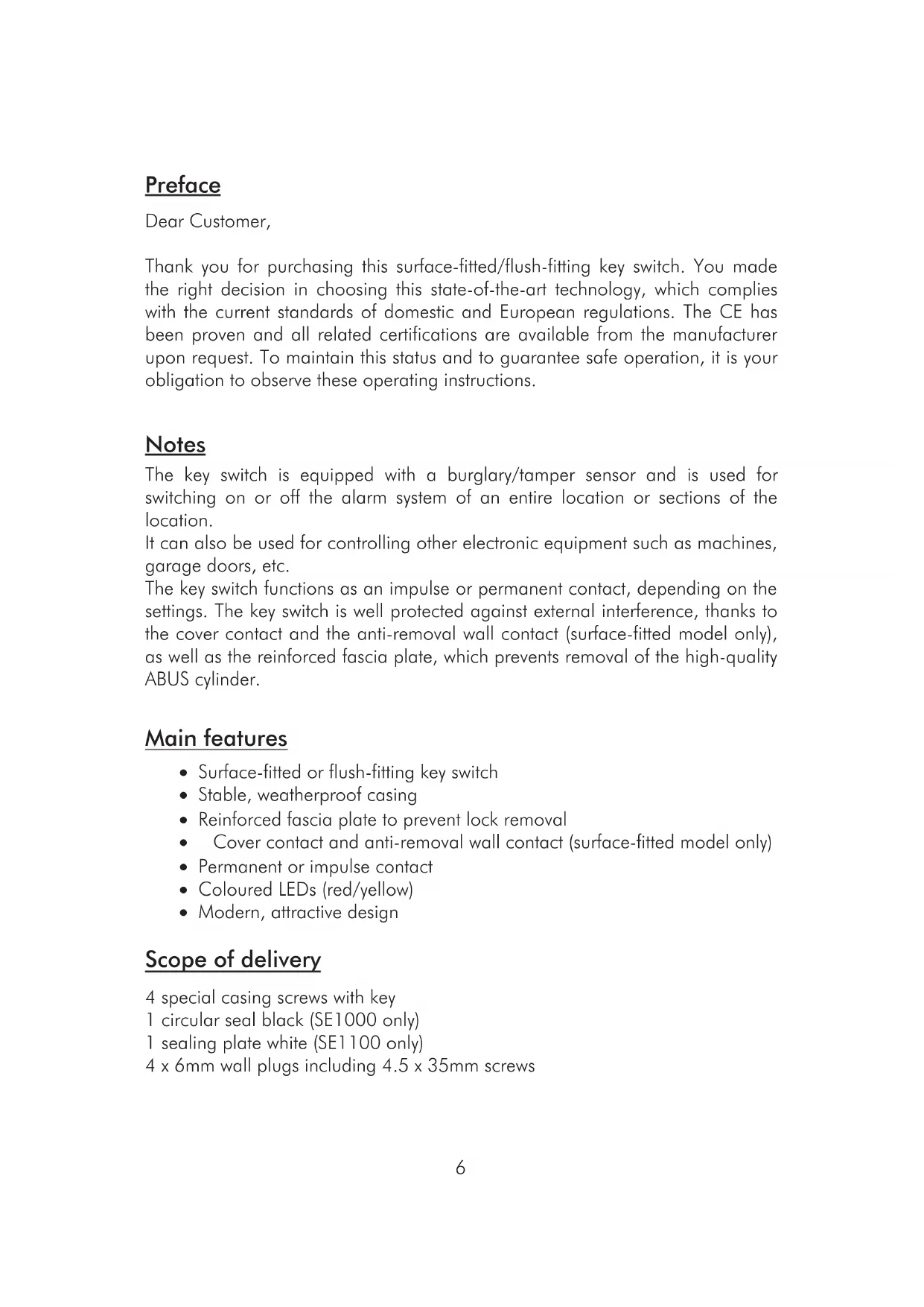
Description
Fig.1 Casing open (with PCB)

Fig. 2 Casing without PCB
1 PCB holder
2 Wall fixing
3 Cable hole
Connections

Note:
The switch position described applies when the cover is open.
Changing switch mode (impulse/permanent contact)

-
The factory setting of the key switch is permanent contact. To change the switch mode:
-
Remove the upper part of the clamp and swing it to the side.
-
The key switch is now set to impulse mode.
Installation
- Using the key supplied, unscrew the cover screws and remove the cover plate.
- Remove the two PCB screws on the left and right of the cylinder.
- Pull the cylinder and PCB carefully upwards and out.
- Use the back of the key-switch case as a template for marking the drill holes (2). Drill the holes for the fixing screws.
- Pull the connector cable through the opening provided.
- Fix the casing to or in the wall.
- Connect the cables to the terminal block (8) as described.
- Replace the PCB in the casing, replace the cover (1) and tighten the cover screws. Make sure that the sealing ring sits firmly in the housing groove.
Technical data
| Voltage supply LED | 10-15 V DC |
| Max. power consumption per LED 2mA | A |
| Maximum contact capacity | 30V DC / 0.5A |
| Dimensions (surface fitting) | 85 x 114 x 42mm (WxHxD) |
| Dimensions (flush fitting) | 106 x 134 x 42mm (WxHxD) |
| Protection type IP55 | |
| Number of contacts | 3 (switchable) |
| Weight 450g |
The manufacturer reserves the right to make technical modifications without prior notice.
Chere cliente, cher client,
Installation Guide. 5


Brand : ABUS
Model : SE1100
Category : Alarm system