KMMF330PBS - Microwave Oven KITCHENAID - Free user manual and instructions
Find the device manual for free KMMF330PBS KITCHENAID in PDF.
User questions about KMMF330PBS KITCHENAID
0 question about this device. Answer the ones you know or ask your own.
Ask a new question about this device
Download the instructions for your Microwave Oven in PDF format for free! Find your manual KMMF330PBS - KITCHENAID and take your electronic device back in hand. On this page are published all the documents necessary for the use of your device. KMMF330PBS by KITCHENAID.
USER MANUAL KMMF330PBS KITCHENAID
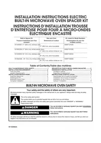
If cabinets are deeper than 13" (33 cm) but no more than 16" (40.6 cm), use the bump out mounting kit to replace the mounting bracket that comes with your unit. These installation instructions are only for the Bump out mounting kit, for full microwave hood combination installation, please refer to the owner manual that came with the microwave hood combination.
Your safety and the safety of others are very important.
We have provided many important safety messages in this manual and on your appliance. Always read and obey all safety messages.

This is the safety alert symbol.
This symbol alerts you to potential hazards that can kill or hurt you and others.
All safety messages will follow the safety alert symbol and either the word "DANGER" or "WARNING."
These words mean:
DANGER
You can be killed or seriously injured if you don't immediately follow instructions.
WARNING
You can be killed or seriously injured if you don't follow instructions.
All safety messages will tell you what the potential hazard is, tell you how to reduce the chance of injury, and tell you what can happen if the instructions are not followed.
INSTALLATION INSTRUCTIONS REQUIREMENTS
Tools and Parts
Tools Needed
■Measuring tape
■Pencil
■Scissors
■Masking tape or thumbtacks
Drill
■No. 2 Phillips screwdriver
■Stud finder
■ No. 3 Phillips screwdriver for 1/4 - 20 x 3" (76 mm) bolts
■ 3/16" (5 mm), 3/8" (10 mm), 5/8" (16 mm) drill bits
■3/4" (19 mm) hole saw
■Keyhole saw
■Diagonal wire cutting pliers
■ 7/16" (11 mm) socket wrench (or box wrench) for 1/4" x 2" (6.4 mm x 51 mm) lag screws
■1 ^1/_2 " (38 mm) diameter hole drill bit for wood or metal cabinet
■Caulking gun and weatherproof caulking compounde
■Duct tape
Materials Needed
- Standard fittings for wall or roof venting. See the “Venting Design Specifications” section.
Parts Needed (Provided in the Microwave Oven)
| Part Drawing | Description Quantity Where can find? | |||
| Screw Pack | 3/16 - 24 x 3" round-head bolts 2 | 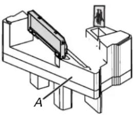 A. Inner Foam in the cavity A. Inner Foam in the cavity | ||
| 1/4 - 20 x 3" flat-head bolts 2 | ||||
| Washers 2 | ||||
| 3/16" toggle nuts 2 | ||||
| 1/4" x 2" lag screws 4 | ||||
| #6 x 3/8" Sheet metal screws 2 | ||||
| Power supply cord bushing | 1 | |||
| Damper | Damper for wall or roof venting | 1 | ||
| Spacer |  | Spacer (L*W*T: 40*10*1.6 mm) | 16 | B. Inside the Literature pack |
Parts Needed (Provided in the Bump Out Mounting Kit)
| Part Drawing Description | Quantity Where can find? | |||
| 13" ~ 14" L BracketBump Out MountingPlate Folded | 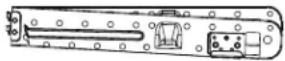 | Folded Mounting plate with Lbracket unfold before installation | 1 | Bump out mountingkit |
| 14" ~ 15" M and NBracket | 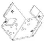 | M side for 14" (35.6 cm) ~ 14 12 " (36.8 cm) depth N side for 14 12 " (36.8 cm) ~ 15" (38.1 cm) depth | 2 | |
| 15" ~ 16" P and RBracket | 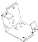 | P side for 15" (38.1 cm) ~ 15 12 " (39.4 cm) depth R side for 15 12 " (39.4 cm) ~ 16" (40.6 cm) depth | 2 | |
| Wall Template Wall Template | 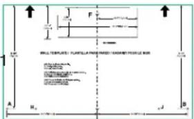 | |||
| Upper Cabinet Template | 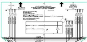 | Upper cabinet template for 13"(33 cm) to 16" (40.6 cm) depthcabinet | 1 | |
| Bump Out Kit InstallationInstruction |  | Installation Instruction 1 |
Keep the mounting plate and cardboard template provided with the microwave oven for future use if necessary.
Location Requirements
Check the opening where the microwave oven will be installed. The location must provide:
→ Minimum installation dimensions. See the “Installation Dimensions” illustration.
→ Minimum one 2" x 4" (51 x 102 mm) wood wall stud and minimum 3/8" (10 mm) thickness drywall or plaster/lath within cabinet opening.
▶ Support for weight of 150 lbs (68 kg) which includes microwave oven and items placed inside the microwave oven and upper cabinet.
→ Grounded electrical outlet inside upper cabinet. See the "Electrical Requirements" section.
NOTE: Some cabinet and building materials are not designed to withstand the heat produced by the microwave oven for cooking. Check with your builder or cabinet supplier to make sure that the materials used will not discolor, delaminate, or sustain other damages.
Special Requirements
For Wall Venting Installation Only:
▶ Cutout must be free of any obstructions so that the vent fit properly and the damper blade opens freely and fully.
For Roof Venting Installation Only:
If you are using a rectangular-to-round transition piece, the 3" (76 mm) clearance needs to exist above the microwave oven so that the damper blade can open freely and fully. See "Rectangular to Round Transition" illustration in the "Venting Design Specifications" section on the Owner Manual on the product.
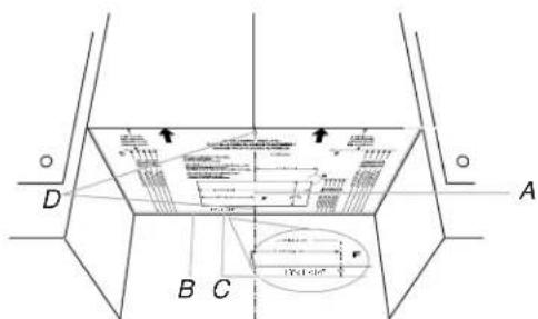
Installation Dimensions
NOTE: The grounded 3 prong outlet must be inside the upper cabinet. See the "Electrical Requirements" section on the Owner Manual on the product.
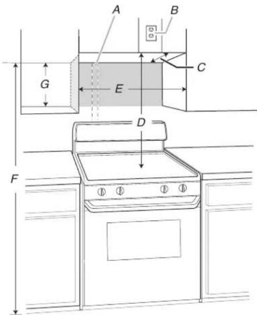
text_image
A B C G E D FA. 2" x 4" (51 mm x 102 mm) wall stud
B. Grounded 3 prong outlet
C. Upper cabinet depth (with door) 13" (33 cm) to 16" (40.6 cm)***
D. 36" (91.4 cm) recommended* 30" (76.2 cm) typical**
E. 30" (76.2 cm) minimum
F. 72" (182.8 cm) recommended 66" (167.6 cm) minimum
G. Flat back surface 18 ^1/4 " (46.3 cm) minimum
Exact dimensions may vary depending on type of range/cooktop below.
*36" (91.4 cm) is recommended for 72" (182.8 cm) installation height.
**30" (76.2 cm) is typical for 66" (167.6 cm) installation height.
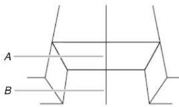
*** Variable depth for 13" (33 cm) to 16" (40.6 cm) cabinet, see below table, the sizes in left column are flush, the size in right column are stands out.
Flush Depth (cabinet + door) S
stand-out Depth
(cabinet + door)
A. (Cabinet + Door)
B. Bump out Mounting plate
A. (Cabinet + Door)
B. Bump out Mounting plate
| L | 13 ^3/_4 " to 14"(35 cm to 35.6 cm) | 13 to 13 ^3/_4 ("33 cm to 35 cm) |
| M | 14 ^1/_4 " to 14 ^1/_2 ("36.2 cm to 36.8 cm) | 14" to 14 ^1/_4 ("35.6 cm to 36.2 cm) |
| N | 14 ^3/_4 " to 15"(37.5 cm to 38.1 cm) | 14 ^1/_2 " to 14 ^3/_4 ("36.8 cm to 37.5 cm) |
| P | 15 ^1/_4 " to 15 ^1/_2 ("38.7 cm to 39.4 cm) | 15" to 15 ^1/_4 ("38.1 cm to 38.7 cm) |
| R | 15 ^3/_4 " to 16"(40 cm to 40.6 cm) | 15 ^1/_2 " to 15 ^3/_4 ("39.4 cm to 40 cm) |
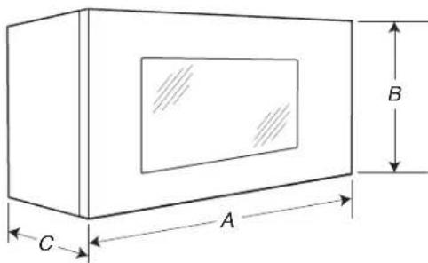
Product Dimensions
text_image
A B CA. 29 ^7 / _8 " (76.1 cm)
B. 17 ^7/8 (45.4 cm)
C. 12 ^1/8 (31.3 cm)
Find the Wall Stud(s)
NOTE: If no wall studs exist within the cabinet opening, do not install the microwave oven.
See illustrations in "Possible Wall Stud Configurations."
- Using a stud finer, locate the edges of the wall stud(s) within the opening.
- Mark the center of each stud, and draw a plumb line down each stud center. See illustrations in "Possible Wall Stud Configurations."
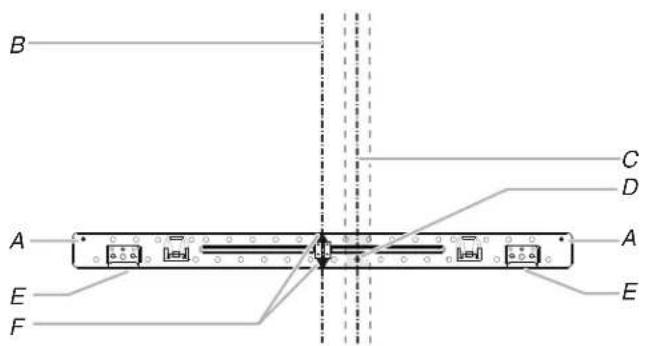
Possible Wall Stud Configurations
These depictions show examples of preferred installation configurations with the mounting plate.
No Wall Studs at End Holes
Figure 1
text_image
B C A E F C D A EA. End holes (on mounting plate)
B. Cabinet opening vertical centerline
C. Wall stud centerlines
D. Holes for lag screws
E. Support tabs
F. Mounting plate center markers
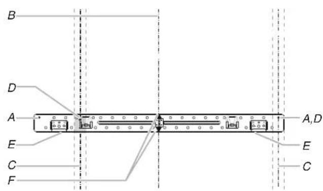
No Wall Studs at End Holes
Figure 2
text_image
B A E F C D A ENOTE: If wall stud is within 6" (15.2 cm) of the vertical centerline, only recirculation or roof venting installation can be done.
A. End holes (on mounting plate)
B. Cabinet opening vertical centerline
C. Wall stud centerlines
D. Holes for lag screws
E. Support tabs
F. Mounting plate center markers
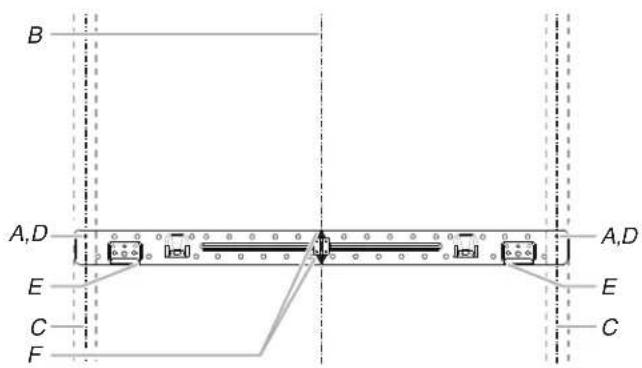
Wall Stud at End Holes
Figure 3
text_image
B D A E C F A,D E CA. End holes (on mounting plate)
B. Cabinet opening vertical centerline
C. Wall stud centerlines
D. Holes for lag screws
E. Support tabs
F. Mounting plate center markers
text_image
B A,D A,D E C F E CA. End holes (on mounting plate)
B. Cabinet opening vertical centerline
C. Wall stud centerlines
D. Holes for lag screws
E. Support tabs
F. Mounting plate center markers
Mark Upper Cabinet
- Using measuring tape, and clearly mark the vertical centerline of the opening. Make sure it is align with the vertical wall centerline.
text_image
A BA. Upper Cabinet Centerline
B. Wall Centerline
The upper cabinet template is fit for depth of 13" (35 cm) to 16" (40.6 cm) cabinet installation, but need some adjustment for different depth. See the following steps.
- Using measuring tape, measure the depth of the cabinet. The upper cabinet template is for variable cabinet depth use, find a dimension of your cabinet in below table.
| Flush Depth (cabinet + door) St | Stand-out Depth(cabinet + door) | |
| L | 13^3/4 " to 14"(35 cm to 35.6 cm) | 13" to 13^3/4 ("33 cm to 35 cm) |
| M | 14^1/4 " to 14^1/2 ("36.2 cm to 36.8 cm) | 14" to 14^1/4 ("35.6 cm to 36.2 cm) |
| N | 14^3/4 " to 15"(37.5 cm to 38.1 cm) | 14^1/2 " to 14^3/4 ("36.8 cm to 37.5 cm) |
| P | 15^1/4 " to 15^1/2 ("38.7 cm to 39.4 cm) | 15" to 15^1/4 ("38.1 cm to 38.7 cm) |
| R | 15^3/4 " to 16"(40 cm to 40.6 cm) | 15^1/2 " to 15^3/4 ("39.4 cm to 40 cm) |
NOTE: There are two install methods, one is flush to the cabinet door, another one is stand-out from the cabinet door. Find the dimension of your cabinet in above table, the dimensions in the left column are flush to the cabinet door, the dimensions in the right column are stand-out from the cabinet door.
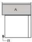
Flush to the cabinet door, front alignment installation, follow below steps:
- For example, the cabinet depth is 14" (35.6 cm), you need to cut or fold the grey portion of the upper cabinet template.
text_image
15" x 1.04" 16" x 0.98 x 0.94 x 1.02" 17" x 0.96 x 0.92" 18" x 0.93 x 0.90" 19" x 0.91 x 0.87"- Place and tape the upper cabinet template against the bottom of the upper cabinet.
NOTES:
Make sure the front edge of the upper cabinet template align with the front edge of upper cabinet.
- Make sure the center marks on the upper cabinet template align with the upper cabinet centerline which draw in step 1.
text_image
C A D BA. Front Edge of the Upper Cabinet Template and Front Edge of Upper Cabinet
B. Upper Cabinet Centerline
C. Arrows on Upper Cabinet Template
D. Center Marks on Upper Cabinet Template
NOTE: If the upper cabinet doors protrude from the upper cabinet, the template can be adjusted outward to be flush with the upper cabinet door.
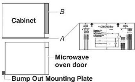
text_image
Cabinet B A Microwave oven door Bump Out Mounting PlateA. Front Edge of Template
B. Upper Cabinet Door
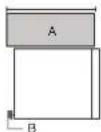
Stand-out from the cabinet door, back alignment installation, follow below steps:
- For example, the cabinet depth is 13 12 " (34.2 cm), you need to cut or fold the grey portion of the upper cabinet template.
text_image
10" x 2.64" 50 x 30 x 31 x 32 44 x 37 x 38 x 39 39 x 42 x 43 x 44 35 x 46 x 47 x 48- Place and tape the upper cabinet template against the bottom of the upper cabinet.
NOTES:
Make sure the L line on the upper cabinet template align with the back edge of upper cabinet.
- Make sure the center marks on the upper cabinet template align with the upper cabinet centerline which draw in step 1.
text_image
D A B CA. Upper Cabinet Centerline and Upper Cabinet Template Centerline
B. Back edge of the Upper Cabinet
C. L Line on Upper Cabinet Template
D. Center Marks on Upper Cabinet Template
Mark Rear Wall
The microwave oven must be installed on a minimum of 1 wall stud, preferably 2, using a minimum of 1 lag screw, preferably 2. See "Find the Wall Stud(s)" section for find the wall studs.
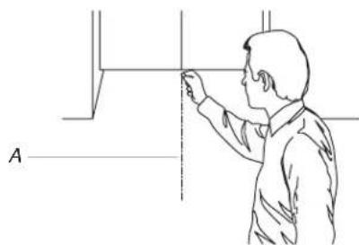
- Using measuring tape, find and clearly mark the vertical centerline of the opening.
natural_image
Line drawing of a person adjusting a vertical panel or fixture (no text or symbols present)A. Centerline
- Tape the Wall template in place. Align the center mark on the wall template over the vertical centerline draw in step 1. Make sure the wall template is level, and that the top of the wall template is butted up against the bottom edge of the upper cabinet.
text_image
A B CA. Bottom Edge of Upper Cabinet and Top of the Wall Template
B. Center Marks on Wall Template
C. Centerline
NOTE: If the front edge of the upper cabinet is lower than the back edge, lower the wall template so that its top is level with the front edge of the cabinet.
text_image
A C D BA. Rear wall
B. Back edge of the Upper Cabinet
C. Top of wall template must align with front edge of cabinet
D. Front edge of upper cabinet
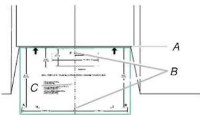
Drill Holes in Upper Cabinet
- Using a 3/4" (1.9 cm) hole saw, cut out the power cord hole (A), which is "G" on the upper cabinet template.
- Drill two mounting nut holes (B), which are 3/8" (10 mm) holes at points "D" and "E" on the upper cabinet template. These are for two 1/4-20 x 3" bolts and washers used to secure the microwave oven to the upper cabinet.
text_image
B AA. Power Cord Hole
B. Mounting Nut Holes
NOTE: If upper cabinet is metal, the supply cord bushing needs to be installed around the supply cord hole as shown.
text_image
A BA. Metal cabinet
B. Power supply cord bushing
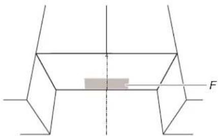
Below steps are for roof venting installation only, skip this steps if for recirculation venting or wall venting installation
-
Cut 3/4 (1.9 cm) hole at one corner of the shaded retangular area "F" on the upper cabinet template.
-
Using a keyhole saw, cut out the rectangular area.
NOTE: If the front edge of the upper cabinet is lower than the back edge, lower the wall template so that its top is level with the front edge of the cabinet.
text_image
Diagram showing a mechanical or structural component with force vector F and a shaded rectangular area between two planes.F. Roof Venting Cutout Area
Drill Holes in Rear Wall
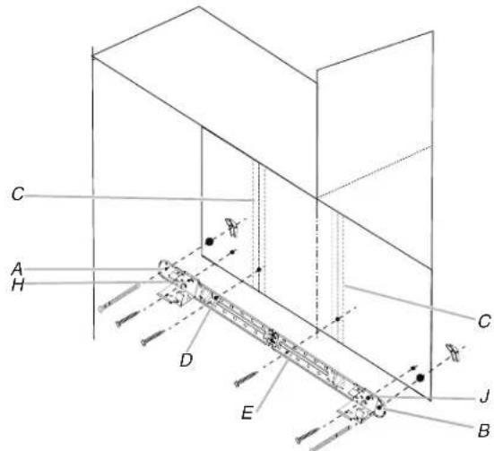
In addition to being installed on at least one wall stud, the mounting plate must attach to the wall at both end holes. If the end holes are not over wall studs, use two 3/16-24 x 3" round head bolts with toggle nuts; if one end hole is over a wall stud, use one lag screw and one 3/16-24 x 3" round-head bolt with toggle nut; or if both end holes are over wall studs, use two lag screws. Following are four installation configurations.
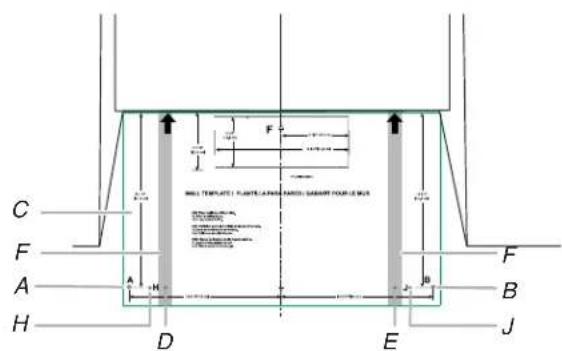
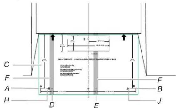
Installation for No Wall Studs at End Holes (See figure 1 in the "Locate Wall Studs" section)
- Drill two 5/8" (1.6 cm) holes through the wall at both end holes (A and B).
- Drill four 3/16" (5 mm) lag screw hole(s), two into the wall studs at the holes (D and E), and two into the wall at the holes (H and J).
text_image
C F A H D E B J F H A H F WALL TEMPLATE: PLANTIC LANDING (SABRIT) FORUM BCA 100mm x 200mm x 300mm x 400mm x 500mm x 600mm x 700mm x 800mm x 900mm x 1000mm x 1100mm x 1200mm x 1300mm x 1400mm x 1500mm x 1600mm x 1700mm x 1800mm x 1900mm x 2000mm x 2100mm x 2200mm x 2300mm x 2400mm x 2500mm x 2600mm x 2700mm x 2800mm x 2900mm x 3000mm x 3100mm x 3200mm x 3300mm x 3400mm x 3500mm x 3600mm x 3700mm x 3800mm x 3900mm x 4000mm x 4100mm x 4200mm x 4300mm x 4400mm x 4500mm x 4600mm x 4700mm x 4800mm x 4900mm x 5000mm x 5100mm x 5200mm x 5300mm x 5400mm x 5500mm x 5600mm x 5700mm x 5800mm x 5900mm x 6000mm x 6100mm x 6200mm x 6300mm x 6400mm x 6500mm x 6600mm x 6700mm x 6800mm x 6900mm x 7000mm x 7100mm x 7200mm x 7300mm x 7400mm x 7500mm x 7600mm x 7700mm x 7800mm x 7900mm x 8000mm x 8100mm x 8200mm x 8300mm x 8400mm x 8500mm x 8600mm x 8700mm x 8800mm x 8900mm x 9000mm x 9100mm x 9200mm x 9300mm x 9400mm x 9500mm x 9600mm x 9700mm x 9800mm x 9900mm x1A and B. Two End Holes
C. Wall Template
D, E, H, and J. Four Lag Screw Holes
F. Wall Stud
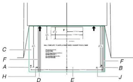
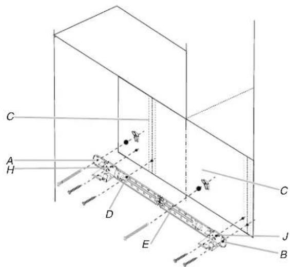
Installation for No Wall Studs at End Holes (See figure 2 in the "Locate Wall Studs" section)
- Drill two 5/8" (1.6 cm) holes through the wall at both end holes (A and B).
- Drill four 3/16" (5 mm) lag screw hole(s), two into the wall studs at the holes (D and E), and two into the wall at the holes (H and J).
text_image
C F A H D E J B F B H A F F FULL TEMPLE: FLUPE-LABOR AND SHAKING FLOW-DRUM 100 mm x 50 mm 200 mm x 50 mm 200 mm x 50 mm 200 mm x 50 mm 200 mm x 50 mm 200 mm x 50 mm 200 mm x 50 mm 200 mm x 50 mm 200 mm x 50 mm 200 mm x 50 mm 200 mm x 50 mm 100 mm x 50 mm 100 mm x 50 mm 100 mm x 50 mm 100 mm x 50 mm 100 mm x 50 mm 100 mm x 50 mm 100 mm x 50 mm 100 mm x 50 mm 100 mm x 50 mm 100 mm x 50 mm 200 mm x 50 mm 200 mm x 50 mm 200 mm x 50 mm 200 mm x 50 mm 200 mm x 50 mm 200 mm x 50 mm 200 mm x 50 mm 200 mm x 50 mm 200 mm x 50mmA and B. Two End Holes
C. Wall Template
D, E, H, and J. Four Lag Screw Holes
F. Wall Stud
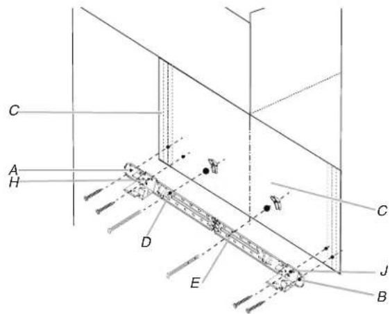
Installation for No Wall Studs at End Holes (See figure 3 in the "Locate Wall Studs" section)
- Drill one 5/8" (1.6 cm) hole through the wall at end holes (A).
- Drill five 3/16" (5 mm) lag screw hole(s), one into the wall studs at the hole (D), and four into the wall at the holes (B, E, H, and, J).
text_image
C F A H D E F B J H F F ALL STRUCTURE PLANTILUM (MATERIALS) GARDY FOR FUEL OF MM 1.5 m 2.0 m 3.0 m 4.0 m 5.0 m 6.0 m 7.0 m 8.0 m 9.0 m 10.0 m 11.0 m 12.0 m 13.0 m 14.0 m 15.0 m 16.0 m 17.0 m 18.0 m 19.0 m 20.0 m 21.0 m 22.0 m 23.0 m 24.0 m 25.0 m 26.0 m 27.0 m 28.0 m 29.0 m 30.0 m 31.0 m 32.0 m 33.0 m 34.0 m 35.0 m 36.0 m 37.0 m 38.0 m 39.0 m 40.0 m 41.0 m 42.0 m 43.0 m 44.0 m 45.0 m 46.0 m 47.0 m 48.0 m 49.0 m 50.0 m 51.0 m 52.0 m 53.0 m 54.0 m 55.0 m 56.0 m 57.0 m 58.0 m 59.0 m 60.0 m 61.0 m 62.0 m 63.0 m 64.0 m 65.0 m 66.0 m 67.0 m 68.0 m 69.0 m 70.0 m 71.0 m 72.0 m 73.0 m 74.0 m 75.0 m 76.0 m 77.0 m 78.0 m 79.0 m 80.0 m 81.0 m 82.0 m 83.0 m 84.0 m 85.0 m 86.0 m 87.0 m 88.0 m 89.0 m 90.0 mA. End Holes
B, E, H, and J. Five Lag Screw Holes
C. Wall Template
F. Wall Stud
Installation for Wall Studs at Both End Holes (See figure 4 in the "Locate Wall Studs" section)
- Drill four 3/16" (5 mm) lag screw hole(s) into the wall studs and wall at the hole (A, B, H, and J).
- Drill 5/8" (1.6 cm) holes through the wall at the hole (D and E).
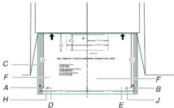
text_image
C F A H D E B J F F ALL TEMPLATE / PLANTS / NAMPS / GARDY / PULB / MUR A B J F F A H D EA and B. Two End Holes
C. Wall Stud
D, E, H, and J. Four Lag Screw Holes
F. Wall Template
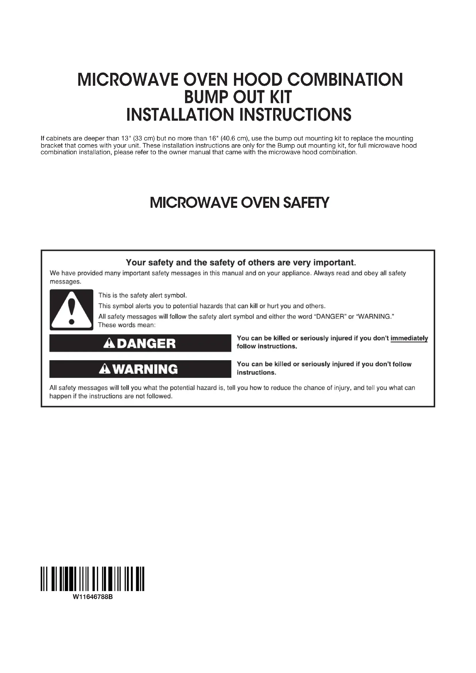
Prepare the Bump Out Mounting Plate
The default bump out mounting plate with L bracket is used for the upper cabinet larger than 13" and up to 14" depth. If your cabinet is 14" to 15", uninstall the L bracket, replace it with the M and N bracket. If your cabinet is 15" to 16", replace it with the P and R bracket. Use the right bracket before attach the bump out mounting plate onto the wall.
If your upper cabinet is larger than 13" and up to 14" depth.
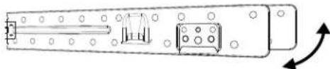
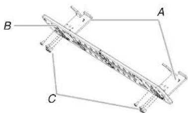
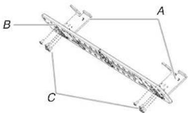
- Take out the bump out mounting plate, which is folded, open it to 180 degree at plate.

natural_image
Technical line drawing of a mechanical component with mounting holes and internal components (no text or symbols)- Attach the bump out mounting plate to wall, follow the steps in "Attach Bumpt Out Mounting Plate to Wall" section.
If your upper cabinet is larger than 14" and up to 15" depth.
- Take out the bump out mounting plate, which is folded, open it to 180 degree at plate.
natural_image
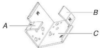
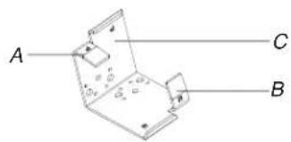
Technical line drawing of a mechanical component with mounting holes and internal components (no text or symbols)- Uninstall the L bracket from the plate. Keep the L bracket for future use.
natural_image
Technical line drawing of a mechanical component with labeled points A, B, and C (no text or symbols beyond labels)A. L Brackets
B. Plate
C. Screws
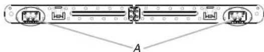
- Select the right hooks for installation, there are two hooks on the M and N bracket, depends on the cabinet depth, select the right hook before installation.
text_image
A B CA. M Hook
B. N Hook
C. M and N Bracket
| Cabinet Depth | |
| M | 14" to 14 12 " (35.6 cm to 36.8 cm) |
| N | 14 ^1/2 " to 15"(36.8 cm to 38.1 cm) |
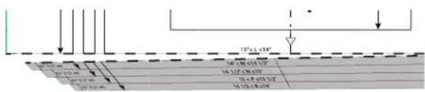
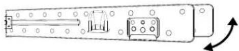
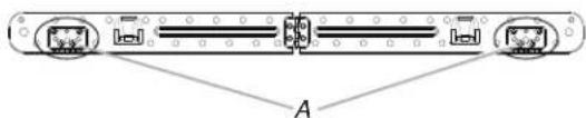
- For example, the cabinet depth is 14^3/4 , choose the N hook, and put the N hooks facing out.

text_image
Technical diagram of a ship's deck with labeled components and annotationsA. N Hook
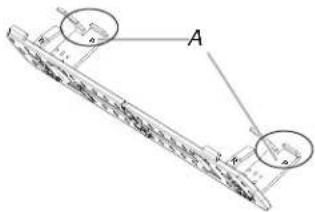
- Fasten M and N bracket with the screws which uninstalled in step 2.
text_image
AA. Screws
If your upper cabinet is larger than 14" and up to 15" depth.
- Take out the bump out mounting plate, which is folded, open it to 180 degree at plate.
natural_image
Technical line drawing of a mechanical component with mounting holes and internal components (no text or symbols)- Uninstall the L bracket from the plate. Keep the L bracket for future use.
natural_image
Technical line drawing of a mechanical component with labeled points A, B, and C (no text or symbols beyond labels)A. L Brackets
B. Plate
C. Screws
- Select the right hooks for installation, there are two hooks on the R and P bracket, depends on the cabinet depth, select the right hook before installation.
text_image
A C BA. P Hook
B. R Hook
C. P and R Bracket
| Cabinet Depth | |
| P | 15" to 15 12 " (38.1 cm to 39.4 cm) |
| R | 15 12 " to 16"(39.4 cm to 40.6 cm) |
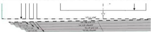
- For example, the cabinet depth is 15^1/4 , choose the P hook, and put the P hooks facing out.
text_image
Technical diagram of a mechanical component with labeled parts A and B, showing internal structure and alignment indicators.A. P Hook
- Fasten P and R bracket with the screws which uninstalled in step 2.
text_image
AA. Screws
Attach Bump Out Mounting Plate to Wall
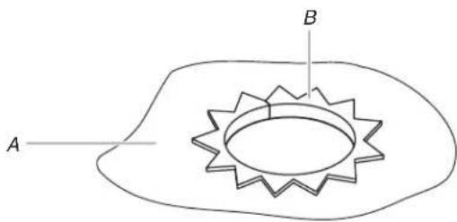
NOTE: Secure the mounting plate to the wall at both end holes drilled into the wall studs and/or drywall using either 3/16-24 x 3" round-head bolts and toggle nuts and 1/4 x 2" lag screws. Refer to illustrations in "Possible Wall Stud Configurations" in the "Locate Wall Stud(s)" section.
Note: If the depth of cabinet is slightly larger than 16", it may be necessary to use a number of the provided spacers, between the mounting plate and the wall, to achieve a more 'Flush' appearance. Stick spacer(s) before position mounting plate on the wall.
natural_image
Pure mechanical diagram showing a cylindrical component with flanged ends and mounting holes, labeled A and B (no text or symbols beyond labels)A. Mounting plate
B. 1/16" thickness
Spacer
| Depth of cabinet Mounting plate |
| 13" to 16" Bump out mounting plate |
| 16 116 " Mounting plate + 4 piece spacer |
| 16 18 " Mounting plate + 8 pieces spacer |
| 16 316 " Mounting plate + 12 piece spacer |
| 16 14 " Mounting plate + 16 pieces spacer |
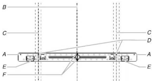
No Wall Studs at End Holes (Figure 1)
NOTE: The mounting plate must be secured to the wall on at least 1 wall stud as well as at both ends.
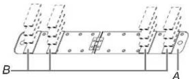
- With the support hooks of the mounting plate facing forward, insert 3/16-24 x 3" round-head bolts through both end holes (A and B), insert 1/4 x 2" lag screws (D, E, H, and J).
text_image
C A H C D E B J CA and B. Two End Holes
C. Wall Studs
D, E, H, and J. Four Lag Screw Holes
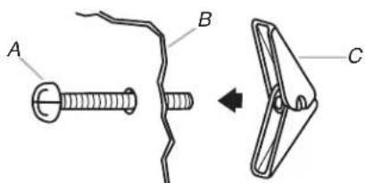
NOTE: Start toggle nuts on bolts from the back of the mounting plate. Leave enough space for the toggle nuts to go through the wall and to open.
text_image
A B CA. 3/16-24 x 3" round-head bolt
B. Mounting plate
C. Spring toggle nut
-
Position mounting plate on the wall.
-
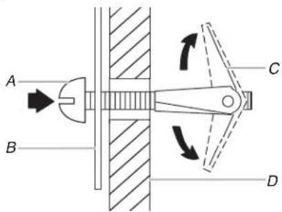
Push the 2 bolts with toggle nuts through the drywall, and finger tighten the bolts to make sure toggle nuts have opened against drywall.
text_image
A B C DA. 3/16-24 x 3" round-head bolt
B. Mounting plate
C. Spring toggle nut
D. Drywall
- Insert lag screw(s) into the hole(s) drilled into wall stud(s) in Step 2 of "Installation for No Wall Studs at End Holes" in the "Drill Holes in Rear Wall" section.
- Check alignment of mounting plate, making sure it is level.
- Securely tighten all lag screws and bolts.
No Wall Studs at End Holes (Figure 2)
Follow the install steps in Figure 1.
text_image
C A H D E C J BA and B. Two End Holes
C. Wall Studs
D, E, H, and J. Four Lag Screw Holes
Wall Stud at End Hole (Figure 3)
Follow the install steps in Figure 1.
text_image
C A H D E J B CA and B. Two End Holes
C. Wall Studs
D, E, H, and J. Four Lag Screw Holes
Wall Stud at End Hole (Figure 4)
Follow the install steps in Figure 1.
text_image
C A H D E C J BA and B. Two End Holes
C. Wall Studs
D, E, H, and J. Four Lag Screw Holes
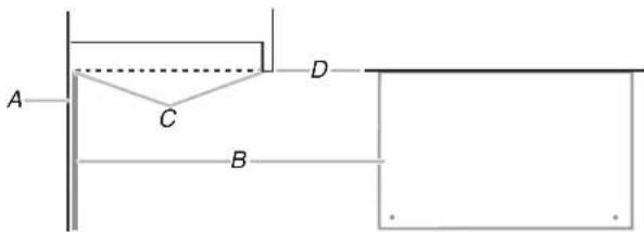
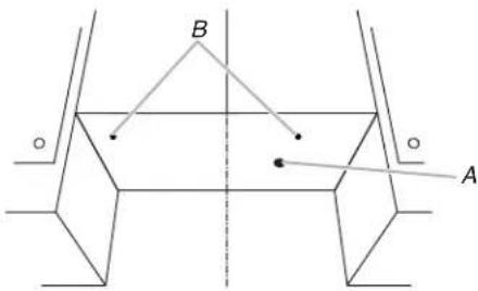
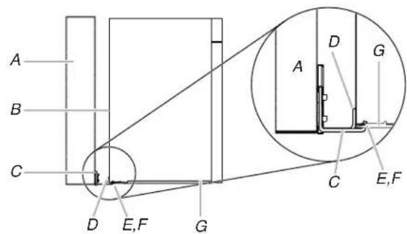
Checking the hooks have been inserted into the right position
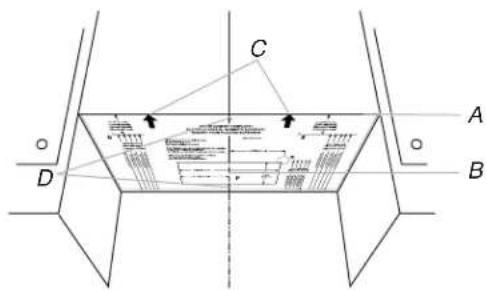
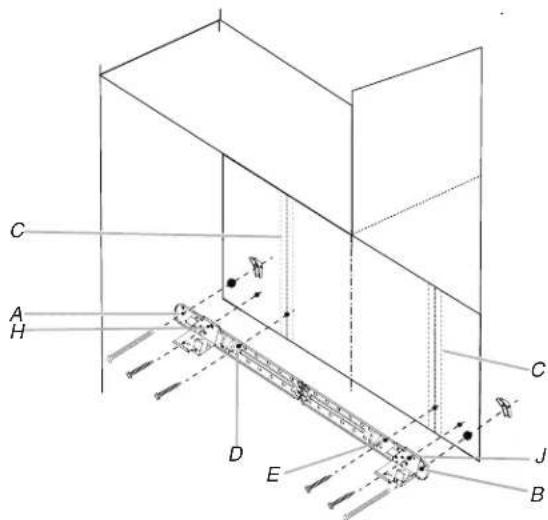
During attaching the microwave oven to the bump out kit, check if the bump out kit hanging hooks have been inserted into the microwave oven bottom plate back holes, and the hanging stoppers against the microwave oven back, reference below illustration. If not in position, adjust the microwave.
text_image
A B C D E,F G A D G C E,FA. Wall
B. Microwave oven back
C. Bump Out Kit
D. Hanging Stopper
E. Hanging Hook
F. Bottom Plate Back Hole
G. Bottom Plate
INSTRUCTIONS D'INSTALLATION DE LA TROUSSE DE MONTAGE DE BOURRELET POUR ENSEMBLE HOTTE/FOUR À MICRO-ONDES
text_image
A B C G E D FA. Montant mural de 2 po x 4 po (51 mm x 102 mm)
text_image
B C A E F C D A Etext_image
B A E F C D A Etext_image
B D A E C F A,D E Ctext_image
B A,D A,D E C F E Cnatural_image
Line drawing of a person adjusting a vertical line with labeled point A (no text or symbols beyond label)A. Axe central
natural_image
Pure geometric diagram of a symmetrical 3D shape with a central shaded rectangle and dashed centerline, no text or symbols present.text_image
C F A H D E J B B F F WALL TEMPLATE / FLUENT LAMP FORING GABINET FORUM BOX 1.5" 2.0" 3.0" 4.0" 5.0" 6.0" 7.0" 8.0" 9.0" 10.0" 11.0" 12.0" 13.0" 14.0" 15.0" 16.0" 17.0" 18.0" 19.0" 20.0" 21.0" 22.0" 23.0" 24.0" 25.0" 26.0" 27.0" 28.0" 29.0" 30.0" 31.0" 32.0" 33.0" 34.0" 35.0" 36.0" 37.0" 38.0" 39.0" 40.0" 41.0" 42.0" 43.0" 44.0" 45.0" 46.0" 47.0" 48.0" 49.0" 50.0" 51.0" 52.0" 53.0" 54.0" 55.0" 56.0" 57.0" 58.0" 59.0" 60.0" 61.0" 62.0" 63.0" 64.0" 65.0" 66.0" 67.0" 68.0" 69.0" 70.0" 71.0" 72.0" 73.0" 74.0" 75.0" 76.0" 77.0" 78.0" 79.0" 80.0" 81.0" 82.0" 83.0" 84.0" 85.0" 86.0" 87.0" 88.0" 89.0" 90.0" 91.0" 92.0" 93.0" 94.0" 95.0" 96.0" 97.0" 98.0" 99.0" 100.0"text_image
C F A H D E J F B B F WALL TEMPLATE: PLANTULAR PANESE GARDEN FROM LIME 100mm x 200mm x 300mm x 400mm x 500mm x 600mm x 700mm x 800mm x 900mm x 1000mm x 1100mm x 1200mm x 1300mm x 1400mm x 1500mm x 1600mm x 1700mm x 1800mm x 1900mm x 2000mm x 2100mm x 2200mm x 2300mm x 2400mm x 2500mm x 2600mm x 2700mm x 2800mm x 2900mm x 3000mm x 3100mm x 3200mm x 3300mm x 3400mm x 3500mm x 3600mm x 3700mm x 3800mm x 3900mm x 4000mm x 4100mm x 4200mm x 4300mm x 4400mm x 4500mm x 4600mm x 4700mm x 4800mm x 4900mm x 5000mm x 5100mm x 5200mm x 5300mm x 5400mm x 5500mm x 5600mm x 5700mm x 5800mm x 5900mm x 6000mm x 6100mm x 6200mm x 6300mm x 6400mm x 6500mm x 6600mm x 6700mm x 6800mm x 6900mm x 7000mm x 7100mm x 7200mm x 7300mm x 7400mm x 7500mm x 7600mm x 7700mm x 7800mm x 7900mm x 8000mm x 8100mm x 8200mm x 8300mm x 8400mm x 8500mm x 8600mm x 8700mm x 8800mm x 8900mm x 9000mm x 9100mm x 9200mm x 9300mm x 9400mm x 9500mm x 9600mm x 9700mm x 9800mm x 9900mm x1natural_image
Technical line drawing of a mechanical component with mounting holes and internal components (no text or symbols)natural_image
Pure mechanical component diagram without any text, numbers, or symbolsnatural_image
Technical line drawing of a mechanical component with labeled points A, B, and C (no text or symbols beyond labels)A. Supports en L
B. Plaque
C. Vis
text_image
Technical diagram of a ship's deck with labeled components and annotationsA. Crochet N
natural_image
Diagram of a mechanical component with internal components and directional arrows (no text or symbols)natural_image
Technical line drawing of a mechanical component with labeled points A, B, and C (no text or symbols beyond labels)A. Supports en L
B. Plaque
C. Vis
natural_image
Pure technical diagram of a mechanical or structural assembly with labeled points A and B, showing no text, numbers, or symbols.text_image
C A H D E C J Btext_image
Diagram showing a mechanical assembly with labeled parts A, B, and C, including a directional arrow indicating transformation.text_image
C A H D E C J Btext_image
C A H D E C J Btext_image
C A H D E C J Btext_image
A B C D E,F G A D G C E,Ftext_image
A B C G E D Ftext_image
B C A E F C D A Etext_image
B A E F C D A Etext_image
B D A E C F A,D E Ctext_image
B A,D E C F A,D E Cnatural_image
Line drawing of a person adjusting a vertical line with labeled point A (no text or symbols beyond label)A. Línea central
natural_image
Pure geometric diagram of a symmetrical 3D shape with a central shaded rectangle and dashed centerline, no text or symbols present.text_image
C F A H D E J B F F H WALL TEMPLET (PLANTILIPAN) MOUNT GABINET FORUM BOX 100mm x 200mm x 500mm x 100mm x 150mm x 200mm x 250mm x 300mm x 350mm x 400mm x 450mm x 500mm x 550mm x 600mm x 650mm x 700mm x 750mm x 800mm x 850mm x 900mm x 950mm x 1000mm x 1050mm x 1100mm x 1150mm x 1200mm x 1250mm x 1300mm x 1350mm x 1400mm x 1450mm x 1500mm x 1550mm x 1600mm x 1650mm x 1700mm x 1750mm x 1800mm x 1850mm x 1900mm x 1950mm x 2000mm x 2050mm x 2100mm x 2150mm x 2200mm x 2250mm x 2300mm x 2350mm x 2400mm x 2450mm x 2500mm x 2550mm x 2600mm x 2650mm x 2700mm x 2750mm x 2800mm x 2850mm x 2900mm x 2950mm x 3000mm x 3050mm x 3100mm x 3150mm x 3200mm x 3250mm x 3300mm x 3350mm x 3400mm x 3450mm x 3500mm x 3550mm x 3600mm x 3650mm x 3700mm x 3750mm x 3800mm x 3850mm x 3900mm x 3950mm x 4000mm x 4050mm x 4100mm x 4150mm x 4200mm x 4250mm x 4300mm x 4350mm x 4400mm x 4450mm x 4500mm x 4550mm x 4600mm x 4650mm x 4700mm x 4750mm x 4800mm x 4850mm x 4900mm x 4950mm x 5000mm xtext_image
C F A H D E J F B B F WALL TEMPLATE: PLANTULAR PANESE GARDEN FROM LIME 100mm x 200mm x 300mm x 400mm x 500mm x 600mm x 700mm x 800mm x 900mm x 1000mm x 1100mm x 1200mm x 1300mm x 1400mm x 1500mm x 1600mm x 1700mm x 1800mm x 1900mm x 2000mm x 2100mm x 2200mm x 2300mm x 2400mm x 2500mm x 2600mm x 2700mm x 2800mm x 2900mm x 3000mm x 3100mm x 3200mm x 3300mm x 3400mm x 3500mm x 3600mm x 3700mm x 3800mm x 3900mm x 4000mm x 4100mm x 4200mm x 4300mm x 4400mm x 4500mm x 4600mm x 4700mm x 4800mm x 4900mm x 5000mm x 5100mm x 5200mm x 5300mm x 5400mm x 5500mm x 5600mm x 5700mm x 5800mm x 5900mm x 6000mm x 6100mm x 6200mm x 6300mm x 6400mm x 6500mm x 6600mm x 6700mm x 6800mm x 6900mm x 7000mm x 7100mm x 7200mm x 7300mm x 7400mm x 7500mm x 7600mm x 7700mm x 7800mm x 7900mm x 8000mm x 8100mm x 8200mm x 8300mm x 8400mm x 8500mm x 8600mm x 8700mm x 8800mm x 8900mm x 9000mm x 9100mm x 9200mm x 9300mm x 9400mm x 9500mm x 9600mm x 9700mm x 9800mm x 9900mm x1natural_image
Diagram of a mechanical component with mounting holes and internal components, showing rotational motion (no text or symbols)natural_image
Technical line drawing of a mechanical component with mounting holes and internal components, showing rotational motion (no text or symbols)natural_image
Pure technical line drawing of a mechanical component with labeled points A, B, and C (no text or symbols beyond labels)A. Soportes en L
B. Placa
C. Tornillos
text_image
Technical diagram of a ship's deck with labeled components and measurement annotationsA. Gancho N
natural_image
Technical line drawing of a mechanical component with mounting holes and internal components (no text or symbols)natural_image
Technical line drawing of a mechanical component with labeled points A, B, and C (no text or symbols beyond labels)A. Soportes en L
B. Placa
C. Tornillos
text_image
Technical diagram of a mechanical component with labeled parts A and B, showing internal structure and assembly details.A. Gancho P
natural_image
Pure technical diagram of a mechanical or structural assembly with labeled points A and B, showing no text, numbers, or symbols.A. Placa de montaje
text_image
C A H D E B C Jtext_image
C A H D E C J Btext_image
C A H D E C J Btext_image
C A H D E C J Btext_image
A B C D E,F G A D G C E,FA. Pared
B. Parte trasera del horno microondas