
FUBE50001 - Alarm system ABUS - Free user manual and instructions
Find the device manual for free FUBE50001 ABUS in PDF.
| Product type | Wireless control element for Secvest alarm system |
| Brand | ABUS |
| Model | FUBE50001 |
| Dimensions (L x W x H) | 120 x 120 x 30 mm |
| Weight | 176 g (without batteries), 246 g (with batteries) |
| Power supply | 3 AA alkaline batteries (1.5 V) or external power supply 9-15 V DC / 9-12 V AC |
| Battery life (without external power) | Approximately 1 year (3 activations/deactivations per day) |
| Radio frequency | 868.6625 MHz |
| Transmission power | max. 10 mW |
| Security technology | Rolling code (switchable) |
| Encryption | 16,777,214 variants |
| Display | 4 status LEDs for partitions (red, green, yellow) |
| Integrated siren | Piezo siren |
| Proximity key reader | Yes (Proximity, can be activated via DIP switch) |
| Protection rating | IP54 (indoor) |
| Operating temperature | -10 °C to +55 °C |
| Humidity | 94% max. (non-condensing) |
| Security grade | 2 (EN50131-1, EN50131-3) |
| Tamper protection | Type B (EN50131-3 §8.7) |
| Compliance | EN50131-1, EN50131-3, EN50131-5-3, EN50131-6; RED, EMC, RoHS, WEEE directives |
| Maintenance | Clean with a soft, dry cloth; replace batteries if necessary |
| Spare parts | AA batteries (standard); external power supply (optional) |
Frequently Asked Questions - FUBE50001 ABUS
User questions about FUBE50001 ABUS
0 question about this device. Answer the ones you know or ask your own.
Ask a new question about this device
Download the instructions for your Alarm system in PDF format for free! Find your manual FUBE50001 - ABUS and take your electronic device back in hand. On this page are published all the documents necessary for the use of your device. FUBE50001 by ABUS.
USER MANUAL FUBE50001 ABUS
Security Tech Germany
DE
natural_image
Technical line drawing of a device casing with control buttons and mounting bracket (no text or symbols)natural_image
Diagram of an electronic device back panel with batteries and components (no text or symbols)
Security Tech Germany
Secvest wireless control panel
EN
Installation instructions and user manual

H 115013

Version 2.9
BOM 13547587

Important
PEACE OF MIND AND SECURITY – THANKS TO THE ROLLING CODE
This control panel uses secure rolling code technology to provide optimum protection against code scanning and code grabbing and thereby preventing unauthorised access.
We are constantly developing our product range in order to provide our customers with optimal, safe products incorporating state-of-the-art technology. We have used this new software to implement a rolling code procedure and optimise processes.

Note
The wireless control panel uses the rolling code system when DIP switch 8 is in the ON position.
The rolling code procedure is compatible with all Secvest (FUAA50xxx) that have up-to-date firmware (>=v2.00.04).
Further details can be found in this manual.
Contents
Introduction 4
Safety information .... 5
Scope of delivery 6
Technical data 7
Functional principle and features ...... 9
Installation and start-up 11
Displays and functions.... 18
Maintenance 23
Warranty 24
Disposal 25
Declaration of conformity 25
Introduction
Introduction
Information on user manual
Dear Customer,
Thank you for purchasing this product. This device is built with state-of-the-art technology.
These instructions contain important installation and operation information for the wireless control panel (last updated 12/2016 with software V2.8). Follow the directions and instructions in this user manual to ensure safe operation. Store this manual in a safe place for future reference. This manual constitutes part of the device. If you pass the device on to third parties, please remember to include this manual.
Intended use
Only use the device for the purpose for which it was built and designed! Any other use is considered unintended!
Limitation of liability
Everything possible has been done to ensure that the content of these instructions is correct. However, neither the author nor ABUS Security-Center GmbH & Co. KG can be held liable for loss or damage caused by incorrect or improper installation and operation or failure to observe the safety instructions and warnings. No liability can be accepted for resulting damage. No part of the product may be changed or modified in any way. If you do not follow these instructions, your warranty claim becomes invalid.
We reserve the right to make changes to this manual without prior notice.
© ABUS Security-Center GmbH & Co. KG, 12/2016
Safety information
Explanation of symbols
The following symbols are used in this manual and on the device:
| Symbol | Signal word | Meaning |
 | Danger | Indicates a risk of injury or health hazards. |
 | Danger | Indicates a risk of injury or health hazards caused by electrical voltage. |
 | Important | Indicates possible damage to the device/accessories. |
 | Note | Indicates important information. |
Battery warning information
The device is powered by three 1.5 V alkaline batteries. To guarantee a long service life and avoid fire and injury, please note the following:

- The batteries must not be exposed to heat or direct sunlight, and must not be stored in places with very high temperatures.
Safety information | Scope of delivery

- The batteries must not be burned.
- The batteries must not come into contact with water.
- The batteries must not be dismantled, pierced or otherwise damaged.
- The battery contacts must not be short-circuited.
- The batteries must be kept away from small children.
- The batteries cannot be recharged.
- Do not dispose of the batteries in domestic waste.
Packaging

- Keep packaging material and small parts away from children. There is a risk of suffocation!
- Remove all packaging material before using the device.
Scope of delivery
- Secvest wireless control panel
• Installation instructions and user manual
• 3 AA alkaline batteries
- Installation material
Technical data
| Dimensions (L x W x H) | 120 x 120 x 30 mm |
| Weight | 176 g (without batteries), 246 g (with batteries) |
| Displays | 4 status LEDs for partitions |
| Operating temperature | -10°C to +55°C |
| Radio frequency | 868.6625 MHz |
| Power | max. 10 mW |
| Humidity | max. 94% (non-condensing) |
| Protection class | IP54 (indoors) |
| Security level | 2 (EN50131-1 §6, EN50131-3 §6) |
| Tamper protection (detection/protection) | Type B (EN50131-3 §8.7) |
| Signals | Integrated piezo sounder |
| Power supply | 3 x AA Alkaline Batteries (Duracell Procell MN1500, Duracell Industrial ID1500, Energizer E91 (optional 9-15 V DC / 9-12 V AC || PSU external) |
| "Low battery" error message | < 3.3 V ("low battery" threshold) |
| Power consumption | 100 mA (nominal) |
| Voltage monitoring | During battery operation without any external power supply (DIP switch 3 activated), only the voltage provided by the batteries is monitored.If the voltage is below the lower threshold of 3.3 V, |
Technical data
| a fault report is sent to the alarm control panel and the user is informed. The external power supply is not monitored in this mode.During operation with an external power supply (DIP switch 3 deactivated), a fault report is sent to the alarm control panel as soon as this is interrupted. The wireless control panel is then automatically powered by the batteries. The corresponding notification on the alarm control panel informs the user about this. How a battery test can be carried out is described above. | |
| • Type of power supply | Type B (50131-1 §9 und 50131-6 §4.1)external power supply via power supply unit and batteries inserted as a backup power supplyType C (50131-1 §9 und 50131-6 §4.1)battery operation only, without external power supply via power supply unitPower supply compliant withEN50131-1:2006+A1:2009 9.2 and EN50131-6 if installed correctly together with Secvest Wireless Alarm System FUAA50xxxINCERT: Type C only |
| • Environmental class | II (EN50131-1 §7, EN50131-3 §7) |
| • Encryption | 16.777.214 ( 2^24 – 2) variants |
| • Certifications | EN50131-3, INCERT (ANPI), VSÖ |
| • Access code | 4-digit or 6-digit |
| • Conformity | The device is compliant with EN 50131-1, EN50131-3:2009, EN50131-5-3 and EN50131-6 security level 2 if installed correctly together with Secvest Wireless Alarm System FUAA50xxx (verified by ANPI). |
Functional principle and features
- EU Directives
RED: 2014/53/EU, EMC: 2014/30/EU, RoHS: 2011/65/EU WEEE: 2012/19/EU, ErP: 2009/125/EC, Low Voltage: 2014/35/EU, General Safety: 2001/95/EC
Functional principle and features
General
The Secvest wireless control panel (FUBE50001) is an optional accessory module for the Secvest wireless alarm system (FUAA50xxx).
It can arm and disarm either the whole wireless alarm system or partitions therein, and it also has an integrated chip key reader.
It is best to power this using an external power supply (PSU). Battery operation is also possible, however, with certain concessions. In this case, please note the warnings surrounding these concessions and those surrounding minimal battery operation further down.
The button on the wireless control panel is freely assignable so that it is possible to control switching outputs on the alarm control panel or to activate one or more sub-areas internally.
As it is classified in protection class IP54, it should only be used indoors.
Functional principle and features
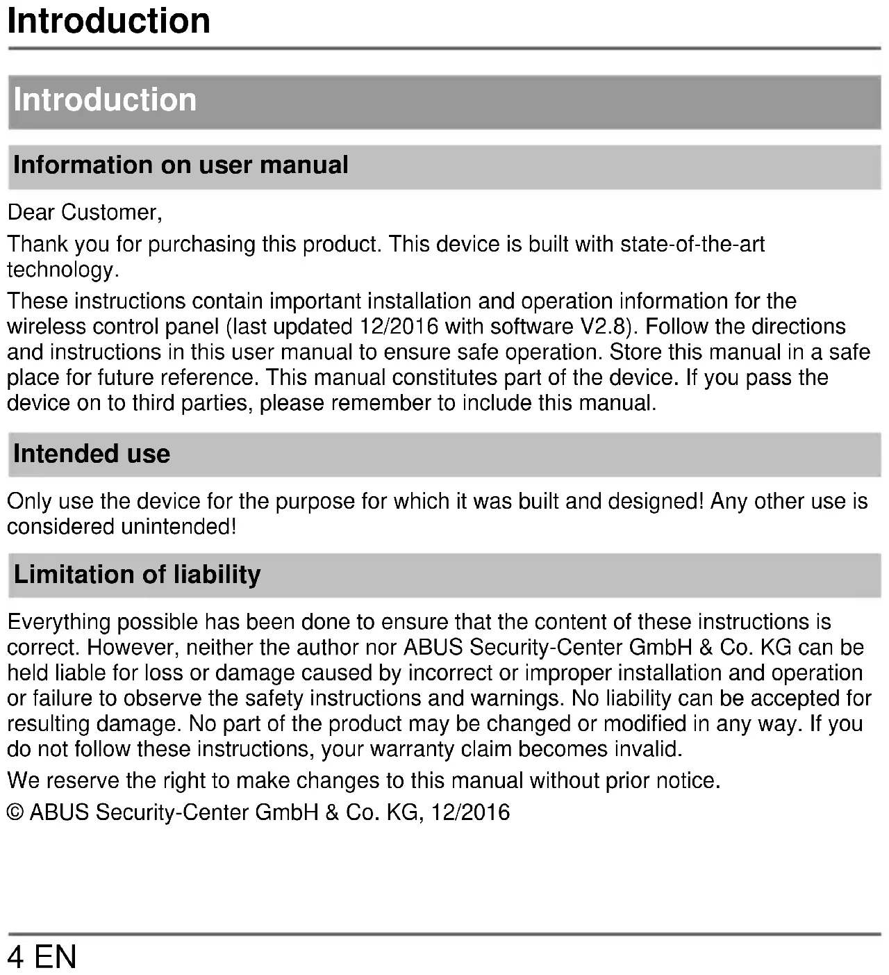
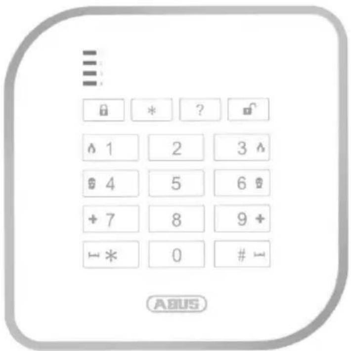
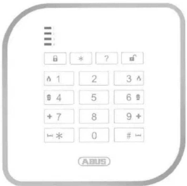
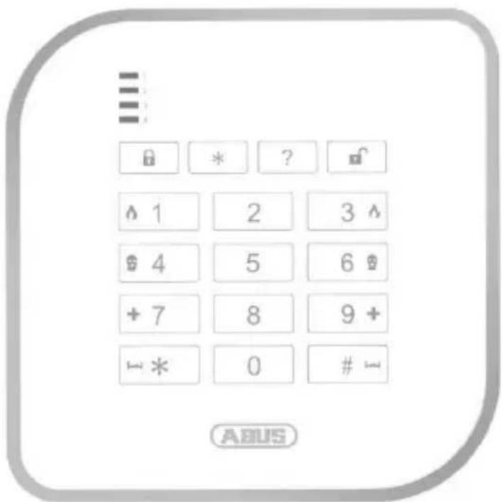
Device description
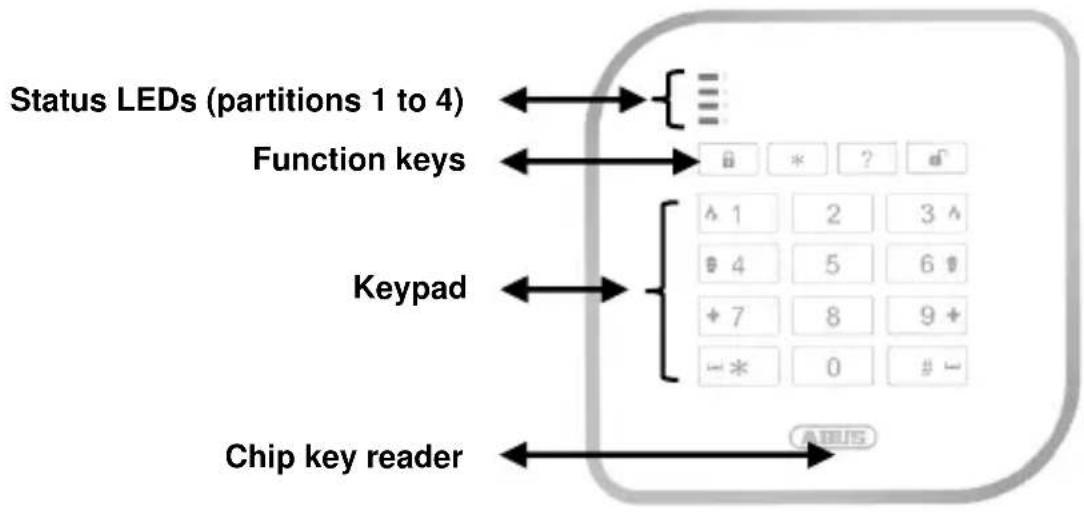
flowchart
graph TD
    A["Status LEDs (partitions 1 to 4)"] <--> B["Function keys"]
    B <--> C["Keypad"]
    C <--> D["Chip key reader"]
    style A fill:#f9f,stroke:#333
    style B fill:#ccf,stroke:#333
    style C fill:#cfc,stroke:#333
    style D fill:#fcc,stroke:#333
LED status display
The control panel's four status LEDs indicate the statuses of the four partitions. The different statuses are indicated as follows:
| RED | → Armed | RED-flashing- | → Transmission to the alarm system |
| GREEN | → Deactivated | GREEN-flashing- | → Wait for confirmation(all 4 LEDs simultaneously) |
| YELLOW | → Internally armed | YELLOW-flashing- | → Interference(separate for each partition) |
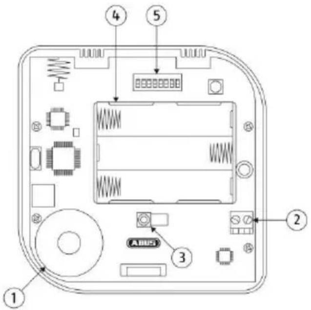
Functional principle and features
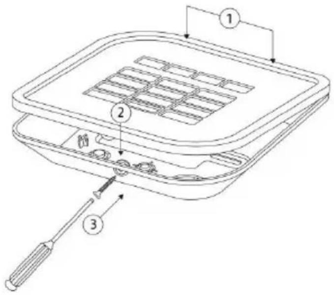
① Piezo sounder
② 12 V connection for power supply unit
③ Tamper contact
④ Battery compartment (3 AA alkaline batteries)
⑤ DIP switch
Installation and start-up
Choosing the installation location
To ensure that the control panel and the proximity chip key reader work correctly, ensure that there are no wires/cables, pipes, metal reinforcements or other relevant installation components within approx. a 50 cm radius of the intended installation location.

Electrical wires and metal objects in particular may disrupt or adversely affect the functions or the behaviour of the proximity chip key reader.
Installing the base plate
Installation and start-up
- Open the wireless control panel housing by removing the screws on the bottom.
- Use the base plate as a drilling template and mark the holes on the wall in the previously selected installation location.

When marking out the drill holes, make sure there are no electrical wires or cables, pipes or other important components behind the mounting location!
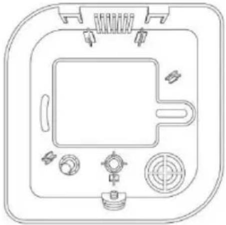
natural_image
Technical line drawing of a device casing with control panel and buttons (no text or symbols)- Drill the holes and insert the screw anchor.
- During operation with an external power supply, insert the cables for the power supply unit from behind into the base plate on the control panel.
- Screw the back of the housing to the wall.
Installation and start-up
DIP switch layout
- Adjust the DIP switch as required.
| Factory/default setting* | Role | OFF | ON | |
| 1 | STATUS LEDPermanent status LEDs | The status of the sub-areas is only displayed for a few seconds during operation* | Permanent status LEDs | |
| 2 | BACK COMPBackward compatibility | FUAA50xxx*All versions of firmwareWorks in same way as FUBE50000 (without rolling code) | FU80xxWorks in same way as FU8110 | |
| 3 | BATT MODEBattery operation | Power supply unit operation(incl. batteries)* | Battery operation(without power supply unit)Suppresses the status message "Ext. PSU error" on the alarm control panel | |
| 4 | INFO TONESInfo and alarm tone sounds on the control panel | No info or alarm tone sounds on the control panel* | Info and alarm tone sounds on the control panel* | |
| 5 | KEY TONESKeypad tones | Keypad tones deactivated* | Keypad tones activated* | |
| 6 | PROX ENBChip key reader | Chip key reader deactivated | Chip key reader activated* | |
| 7 | KEY LEDPermanent keypad lighting | Keypad lighting during operation only*(times out after 15 seconds) | Permanent keypad lighting | |
| 8 | NURolling code | WITHOUTRolling codeCompatibility as per DIP-2 | WITHrolling code*Compatible with Secvest FUAA50xxx firmware>=v2.00.03DIP-2 without effect | |
Installation and start-up
- The "Permanent Status LEDs", "Permanent Key Lighting" and "Info and Alarm Tone Sounds on the control panel" functions are only available during operation with an external power supply.
- For the "Info and Alarm Tone Sounds on the Control Panel" and "Permanent Status LEDs" functions, "Broadcast Panel Status" must be activated on the alarm control panel.
- For the "Info and Alarm Tone Sounds on the Control Panel" function, the "Permanent Status LEDs" function must also be switched to ON.
- In order to use the chip key function, we recommend using an external 12 V power supply. Although the use of this function is possible without an external power supply, this will make chip key recognition slower and will shorten the wireless control panel's battery life.

If you would like to change the operating mode of the control panel using DIP switch eight and two, you will need to first wipe the control panel from the Secvest and then teach it in again.
Changes via other DIP switches should be made only when the device is not connected to a power source and the tampering switch is open.
Start-up
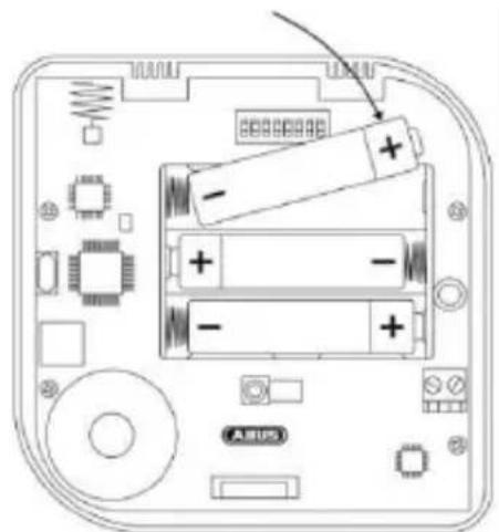
natural_image
Diagram of an electronic device back panel with batteries and components (no text or symbols)- Insert the three AA alkaline batteries in the battery compartment.
Make sure the polarity is correct!

As a rule, if it is possible, an external power supply should be used. In this case, the batteries act as a reserve power supply. If an external power supply is not possible, the control panel can also be used with certain concessions in battery mode. The actual battery life is, in this case, largely dependant on the functions being carried out (Prox reader, key pad lighting)
Installation and start-up
as well as how frequently they are being carried out via the control panel! The length of battery life when operating without an external power supply and under the following conditions is roughly one year: arming 3x daily, disarming 3x daily, Prox calibration once daily (automatic process), no exit time programmed.
LED test/software version display

If the tamper contact is open when the control panel starts up, the following LED test will be performed and the software version displayed.
(1.) All four status LEDs (sub-areas 1 to 4) flash red to confirm that they are working.

The software version of the control panel is displayed in sequence by the red "RF TX" and the green "TEST" LED. Both LEDs are located on the PCB close to the DIP switch.
(2.) The red transmitting LED (RF TX) indicates the major software version.
(3.) The green test LED (TEST) indicates the minor software version.
Example: 2 x flashing "RF TX" (red) → 5 x flashing "TEST" (green) → Software version "2.5"

If the tamper contact is closed when the control panel starts up, the aforementioned tests will not be performed.
Automatic calibration of the chip key reader
If the DIP switch 6 (chip key reader) is activated when the control panel starts up, calibration will be performed automatically as soon as the LED test is completed and the software version is displayed.

During the calibration of the chip key reader, the status LEDs for sub-areas 1 to 4 light up one after the other (sequence of lights from top to bottom).
Displays and functions
If DIP switch 6 (chip key reader) is deactivated when the control panel starts up, calibration will be performed as soon as the DIP switch is activated.

The chip key reader re-calibrates itself automatically every 24 hours to compensate for changes to the environmental conditions and to ensure correct functioning.
Manual calibration of the chip key reader
You can also start the calibration manually by pressing the and keys simultaneously. This is required whenever changes to environmental conditions are impeding the chip key reader's functions.

Keep the chip key and any other metal objects away from the chip key reader during calibration to avoid disrupting the process!

If the control panel has a 12 V connection, the proximity reader will be permanently operational, which is why the manual calibration is deactivated via keys and .
The calibration upon start up and the calibration every 24 hours is deactivated.
Installation and start-up
- Teach in the wireless control panel (see chapter "Read-in process") and lock the cover in place.
- Once installation and commissioning have been completed, start the calibration of the chip key reader manually by pressing the 2 and keys at the same time.

The control panel must be closed and screwed in at this point, and positioned in its final installation location.

During the calibration of the chip key reader, the status LEDs for sub-areas 1 to 4 light up one after the other (sequence of lights from top to bottom).

Keep the chip key and any other metal objects away from the chip key reader during calibration to avoid disrupting the process!
Displays and functions
Displays and functions
Teach-in process
- Set the Secvest to "teach-in mode" (see installation instructions for wireless alarm system) and send a teach-in signal from the wireless control panel to the wireless alarm system.
- The teach-in signal can be sent either by inserting the batteries or by activating the tamper switch.
- Once the teach-in signal has been picked up by the wireless alarm system, it will emit two beeps and the incoming signal strength will be displayed.
- Confirm the successfully completed teach-in on the control panel.
operation


- You can cancel incorrect code entries by pressing the star key (see adjacent figure).
- If the user code is entered incorrectly three times, the control panel keypad will flash and will be locked for 5 minutes.
Displays and functions
Keypad lighting
The brightness of the keypad lighting can be adjusted using the following key combination:
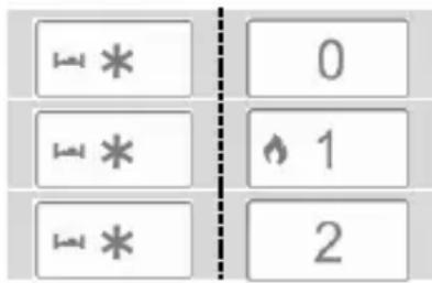
Keypad lighting deactivated(Factory Default)
Brightness level 1
Brightness level 2

The keys must be pressed one after the other (not simultaneously) here.
Operating mode
You can control the wireless alarm system via the control panel in any of the three operating modes:
| Operating mode | Authentication |
| Type in code | 4-digit or 6-digit code |
| Prox Tag | registered chip key |
| "Quick start" | - none - |
This can be configured within the wireless alarm system.

- For authentication, take a chip key which has been previously recognised by the wireless alarm system and hold it over the ABUS logo on the control panel.
Displays and functions
Exit delay

If you want the alarm panel to be armed after allowing for a set exit delay, this can also be configured within the wireless alarm system.
Arming the whole wireless alarm system or individual partitions

→ Perform authentication in line with the configured control panel operating mode.
(1.) Press the "arm" button to arm the entire wireless alarm system.
(2.) Press the key followed by the relevant numbers for the individual sub-areas which you want to be armed. Confirm your selection by pressing the button in order to arm the selected sub-areas.
Disarming the wireless alarm system

→ Perform authentication in line with the configured control panel operating mode.
→ Disarm the wireless alarm system by pressing the "disarm" button.
Status query

→ Perform authentication in line with the configured control panel operating mode.
→ Run a status query for the wireless alarm system by pressing the "status query" button.
→ The LED display indicates the status of the different partitions.
Arm internally/Switch output

→ This button can be used either for arming internally or for switching one (or more) wireless alarm system output(s). This can be configured within the wireless alarm system.
Displays and functions
Manual alarm triggering without previous authentication
By pressing two function buttons simultaneously, you can trigger an alarm via the wireless control panel without needing to enter a code. This function must, however, already be enabled within the wireless alarm system:
→ Fire alarm


→ Panic alarm


→ Medical emergency call


→ Nursing emergency call


Press and hold the aforementioned buttons until the 4 status LEDs flash red, confirming that the alarm has been sent successfully.
Maintenance
In the case that an external power supply is being used please remember to replace the batteries before their expiry date.
If the batteries need to be replaced, the alarm control panel will display the error message "FKBDT == batt low". In this case, the batteries should be replaced by an installer.
The keys of the control panel must undergo functional testing every year; the device must also be cleaned.
Make sure that the system is not operating before carrying out the functional testing for the keys.
In installer mode, select "Test → wireless control panel → wireless control panel 01-08".
Select the wireless control panel required. The display now shows "Press key to test". Press the keys on the control panel as follows in order to test them:
- Press 4 or 6 (numerical) buttons on the keypad in sequence, followed by a function button: The display now shows the keys that were pressed – e.g. "1234A".
| A = | B = | C = | D = |
- Press both fire, hold up, medical or social care buttons simultaneously to test the manual trigger function of alarms. The display now shows the respective abbreviations.
| F = | 1 \ 3 | P = | 4 \ 6 | M = | +7 \ 9+ | H = | ←* \ \# ← |
Clean the outside of the housing with a soft, dry cloth. Do not use water or any form of solvent or cleaning agent.
Warranty

- ABUS products are designed and manufactured with the greatest care and tested according to the applicable regulations.
- The warranty only covers defects caused by material or manufacturing errors at the time of sale. If there are demonstrable material or manufacturing errors, the product will be repaired or replaced at the guarantor's discretion.
- In such cases, the warranty ends when the original warranty period of two years expires. All further claims are expressly rejected.
- The warranty does not cover the batteries supplied.
- ABUS will not be held liable for defects and damage caused by external influences (e.g. transport, use of force, operating errors), inappropriate use, normal wear and tear or failure to observe the instructions in this manual.
- In the event of a warranty claim, the original receipt with the date of purchase and a short written description of the problem must be supplied with the product.
- If within the first two years following purchase you discover a defect on your product which existed at the time of purchase, contact your dealer directly.
Disposal | Declaration of conformity
Disposal
Dispose of the device in accordance with EU Directive 2012/19/EU – WEEE (Waste from Electrical and Electronic Equipment). If you have any questions, please contact the municipal authority responsible for disposal. You can get information on collection points for waste equipment from your local authority, from local waste disposal companies or your dealer, for example.
Declaration of conformity
Hereby, ABUS Security-Center GmbH & Co. KG declares that the radio equipment type FUBE50001 is in compliance with Directive 2014/53/EU.
The full text of the EU declaration of conformity is available at the following internet address: www.abus.com, Item search FUBE50001/Downloads.
The Declaration of Conformity can also be obtained from the following address:
Security Tech Germany
NL
natural_image
Technical line drawing of a device casing with control panel and buttons (no text or symbols)natural_image
Diagram of an electronic device rear panel with batteries and components (no text or symbols)
FR
natural_image
Top-down schematic of a device panel with control buttons and a central screen (no text or symbols)natural_image
Top-down view of an electronic device showing battery pack, circuit board, and labeled components (no readable text or symbols)
Security Tech Germany
Montering & idrifttagning
natural_image
Technical line drawing of a device casing with control panel and buttons (no text or symbols)natural_image
Diagram of an electronic device rear panel with batteries and components (no readable text or symbols)

ES
natural_image
Line drawing of a device control panel with buttons and a central screen (no text or symbols)natural_image
Diagram of an electronic device back panel with batteries and components (no text or symbols)


- Secvest wireless control panel
- 5 6 #
- Important
- Note
- Contents
- Introduction
- Information on user manual
- Intended use
- Limitation of liability
- Safety information
- Explanation of symbols
- Battery warning information
- Safety information | Scope of delivery
- Packaging
- Scope of delivery
- Functional principle and features
- General
- Device description
- LED status display
- Installation and start-up
- DIP switch layout
- Start-up
- LED test/software version display
- Automatic calibration of the chip key reader
- Displays and functions
- Teach-in process
- operation
- Keypad lighting
- Operating mode
- Arming the whole wireless alarm system or individual partitions
- Disarming the wireless alarm system
- Status query
- Arm internally/Switch output
- Manual alarm triggering without previous authentication
- Maintenance
- Warranty
- Disposal | Declaration of conformity
- Disposal
- Declaration of conformity
- 5 6 #
- Montering & idrifttagning
Brand : ABUS
Model : FUBE50001
Category : Alarm system